

MICROTHERM indoor air quality &
WinIaq Application Software - User Manual
MICROTHERM
indoor air quality
WinIaq Application Software
User Manual
HB3264-06
November 2002
&
COPYRIGHT
The copyright in this document which contains proprietary information is vested in
CASELLA CEL LIMITED. The contents of this document must not be used for
purposes other than for which it has been supplied or reproduced or disclosed wholly
or in part without the prior written permission of
CASELLA CEL LIMITED
CASELLA CEL
Regent House
Wolseley Road
Kempston
Bedford
MK42 7JY, U.K.
Phone: +44 (0)1234 844100
Fax: +44 (0)1234 841490
E-Mail: info@casellacel.com
Web: www.casellacel.com
CASELLA USA
17 Old Nashua Road #15
Amherst
NH 03031,
U.S.A.
Toll Free: +1 800 366 2966
Fax: +1 603 672 8053
E-mail: info@casellausa.com
Web: www.casellausa.com

MICROTHERM indoor air quality &
WinIaq Application Software - User Manual
Page 2 of 42

MICROTHERM indoor air quality &
WinIaq Application Software - User Manual
Table of Contents
Chapter . . . . . . . . . . . . . . . . . . . . . . Page
1. INTRODUCTION TO THE MICROTHERM . . . .......... 5
2. ASSEMBLING THE MICROTHERM ................ 6
2.1 Assembly ....................... 6
2.2 Sensors........................ 6
2.3 MainsPower...................... 7
2.4 Communications .................... 7
2.5 Disassembly ...................... 7
3. MICROTHERM CONTROL UNIT . ................ 8
3.1 Indicators . ...................... 8
3.2 Liquid Crystal Display . ................ 8
3.3 Control keys ...................... 8
3.4 Internal Battery .................... 9
Contents
4. WinIaq ...........................10
®
4.1 Installation on Windows 3.1
4.2 Installation on Windows 95
4.3 Starting Win
5. MICROTHERM PROFILES - BASIC ................11
5.1 Creating a New Profile . ................11
5.2 Defining the Serial Interface ..............11
5.3 ChoosingSensors ...................12
5.4 Parameters ......................12
5.5 Transferring Profiles . . ................13
6. DATA RECOVERY . ......................15
7. DISPLAYING DATA ......................16
7.1 Displaying Data as a Graph ...............16
7.1.1 Selecting the Time Base ................16
7.1.2 Selecting a Different Trace ...............17
7.1.3 Changing the Vertical Scale ..............17
7.2 Displaying Data as a Table ...............18
7.2.1 Table Font Size ....................18
7.3 Creating a Summary . . ................18
Iaq ....................10
.............10
®
..............10
8. PRINTING & EXPORTING DATA . ................20
8.1 Printing Data .....................20
8.2 Exporting Data ....................20
Page 3 of 42

Contents
WinIaq Application Software - User Manual
MICROTHERM indoor air quality &
Table of Contents
Chapter . . . . . . . . . . . . . . . . . . . . . . Page
9. MICROTHERM PROFILES - ADVANCED . . . ..........21
9.1 Changing the Recording Interval . . ..........21
9.2 Setting an Alarm . . . ................21
9.3 Changing the Recording Method . . ..........22
9.4 Changing the Calculation Constants . ..........22
9.5 Enabling Real Time Data Output . . ..........23
9.6 ModemOperation ...................24
10. EXTERNALCONNECTIONS ................. 25
10.1 Alarm Connector ....................25
11. USING PCMCIA MEMORY CARDS . . . . . . . . . . . . . . 26
11.1 Dedicated Card Reader . ................26
11.1.1 Clearing a Card ................... 26
11.1.2 Extracting Data From a Card ............. 26
11.2 Existing PCMCIA Card Sockets (CardWizard) . . ....27
11.2.1 DeCopy . . ......................27
11.2.2 De
12. SENSOR SPECIFICATIONS . . . . . . . . . . . . . . . . . 29
12.1 Black Globe Thermometer ...............29
12.2 Air Velocity Probe . . . ................30
12.3 Solid State Temperature and Humidity Probe . . ....31
12.4 Natural Wet Bulb Thermometer . . . ..........32
12.5 CO
12.6 Airborne Particulate Monitor ..............35
12.7 CO Gas Detector ....................36
12.8 O
12.9 CEL-254 Sound Level Meter ..............38
Appendix 1 ...........................39
A1.1 Introduction ......................41
A1.2 Installation ......................41
A1.3 Operation . ......................42
Image .......................28
Monitor ......................33
2
Gas Detector ....................37
2
Page 4 of 42
MICROTHERM indoor air quality &
WinIaq Application Software - User Manual
Introduction
1. INTRODUCTION TO THE MICROTHERM
Increasing our knowledge of the indoor environment is essential in assessing the
welfare of buildings and their occupants. This is of particular importance to
workplaces, where maintaining the best possible working conditions ensures
optimum levels of workforce efficiency.
The MICROTHERM indoor air quality is the product of CASELLA CEL’s many years
of research, development and production of leading edge environmental
monitoring products.
The MICROTHERM system is designed to monitor, record, calculate and display
valuable data relating to the indoor environment of enclosed or partially
enclosed spaces. These environments usually relate to buildings in which:
¤ Human work activity occurs.
¤ Industrial processes are undertaken.
¤ Materials and goods are stored or exhibited.
¤ Animals or plants are housed.
The MICROTHERM is totally portable and is ideal for both fixed site and portable
general survey applications. Supplied in a robust carrying case, the complete
system is easily transported by a single operator.
The overall sensor design and data generation complies with the general
guidelines of the European ISO recommendations.
The accompanying Windows software has been developed to make programming
of the MICROTHERM, together with the collection and presentation of data as
simple as possible.
Page 5 of 42
Assembly
WinIaq Application Software - User Manual
MICROTHERM indoor air quality &
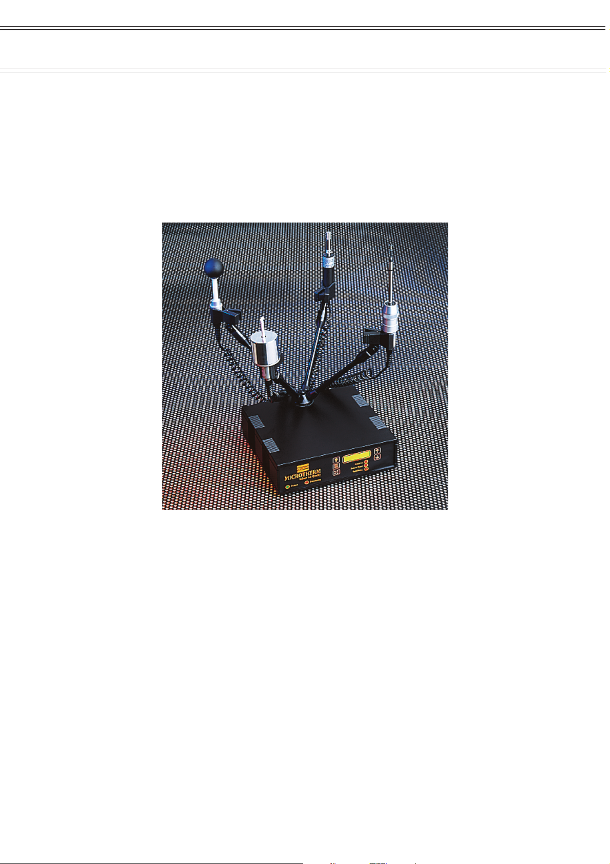
2. ASSEMBLING THE MICROTHERM
The MICROTHERM control unit is supplied in a hard wearing carry case with
sufficient room to house the basic complement of sensors. Prior to use the
MICROTHERM must be assembled and programmed.
2.1 Assembly
To assemble the MICROTHERM prior to use, remove the control unit from the
carrying case and place on a secure level surface.
If fitted, remove the blanking plug from the hub mounting hole located on the
top cover of the control unit.
Locate the small hub over the mounting hole and secure using the hub retaining
screw.
Screw a sensor retaining arm into each of the four holes located in the small hub
making sure the sensor clip on each arm ends up in a vertical position. Lock
each arm in position using the ‘locking collar’ at the base of each arm.
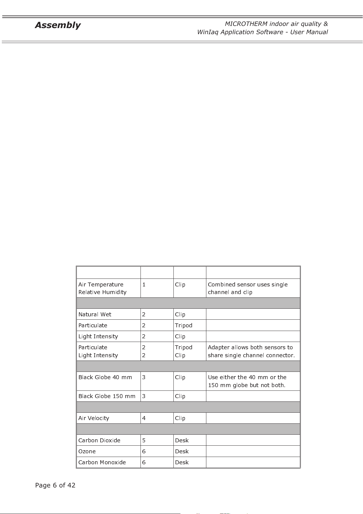
2.2 Sensors
Arrange the required sensors using the available “sensor clips” and insert the
connector in the associated socket located on the back panel. Note that not all
the sensors can be mounted using the “sensor clips” and that some
combinations of sensors are not permissible as they use the same sockets.
The following table outlines possible sensor allocations.
Sensor Channel Mount Combination
Air Temperature
Relative Humidity
Natural Wet 2 Clip
Particulate 2 Tripod
Light Intensity 2 Clip
Particulate
Light Intensity
Black Globe 40 mm 3 Clip Use either the 40 mm or the
1 Clip Combined sensor uses single
channel and clip
2
2
Tripod
Clip
Adapter allows both sensors to
share single channel connector.
150 mm globe but not both.
Page 6 of 42
Black Globe 150 mm 3 Clip
Air Velocity 4 Clip
Carbon Dioxide 5 Desk
Ozone 6 Desk
Carbon Monoxide 6 Desk
MICROTHERM indoor air quality &
WinIaq Application Software - User Manual
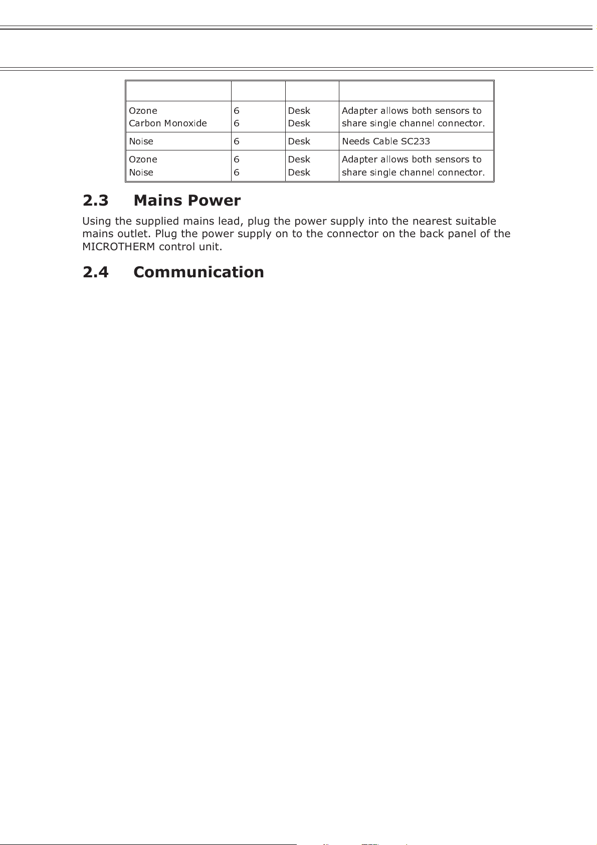
Sensor Channel Mount Combination
Assembly
Ozone
Carbon Monoxide
Noise 6 Desk Needs Cable SC233
Ozone
Noise
6
6
6
6
Desk
Desk
Desk
Desk
Adapter allows both sensors to
share single channel connector.
Adapter allows both sensors to
share single channel connector.
2.3 Mains Power
Using the supplied mains lead, plug the power supply into the nearest suitable
mains outlet. Plug the power supply on to the connector on the back panel of the
MICROTHERM control unit.
2.4 Communications
Using the supplied serial communication cable, connect the RS232 connector
located on the rear panel of the MICROTHERM control unit to a free RS232 port
on your computer.
Switch the MICROTHERM control unit ON by moving the switch on the back
panel to the down position.
2.5 Disassembly
Disassembly of the control unit ready for storage or transportation is a matter of
following the same procedure as for assembly, except in the reverse order.
At this point you are ready to program and record data using the combination of
MICROTHERM control unit and Win
Iaq application software.
Page 7 of 42

Control Unit
WinIaq Application Software - User Manual
MICROTHERM indoor air quality &
3. MICROTHERM CONTROL UNIT
A number of indicators and control keys are accessible on the front panel of the
instrument. The indicators give visual feedback about the current state of the
MICROTHERM while the control keys allow you to view current readings and stop
and start the unit.
3.1 Indicators
There are two light emitting diodes (LEDs) situated at the left end of the front
panel.
Power, green LED lit when mains power is available and the unit is ON.
Processing, red LED flashes when the unit is processing data internally.
There are three LEDs situated below the display at the right end of the front
panel.
Logging, red LED flashes when a data set is committed to memory.
Sensor read, red LED flashes when attached sensors are scanned.
Halt/delay, will flash during the initial delay period then remain off
until the MICROTHERM stops logging were upon it will remain lit.
3.2 Liquid Crystal Display
A two line by 16-character liquid crystal display (LCD) allows you to scroll
through the current values read from the sensors, together with any calculated
values. The display has an integral back light to enhance visibility in low light
conditions.
3.3 Control Keys
The MICROTHERM has five keys positioned around the liquid crystal display.
F
The function key modifies the operation of the other four keys, when
pressed it changes the display to show the alternate function
associated with each key.
The back light key toggles the liquid crystal display back light on and
off. Normally, this key has no alternate function associated with it,
except when memory cards for data retrieval are in use (see Appendix
1).
Page 8 of 42
The scroll key has no function currently associated with it. This key
has no alternate function associated with it.
The up key scrolls up through the list of current readings. Holding the
key down for 3 seconds causes the display to scroll automatically in
this direction. The scrolling action will continue until the key is pressed
again.

MICROTHERM indoor air quality &
WinIaq Application Software - User Manual
The alternate function associated with this key is the start function.
Pressing this key in combination with the function key will cause the
MICROTHERM to initialise itself and begin logging. This does not affect
any data currently held within the MICROTHERM as this can be erased
only by reprogramming via the Win
The down key scrolls down through the list of current readings.
Holding the key down for 3 seconds causes the display to scroll
automatically in this direction. The scrolling action will continue until
the key is pressed again.
The alternate function associated with this key is the stop function.
Pressing this key in combination with the function key will cause the
MICROTHERM to stop logging. To resume logging use the alternate up
key function. This does not affect any data currently held within the
MICROTHERM as this can be erased only by reprogramming via the
Iaq application.
Win
Control Unit
Iaq application.
3.4 Internal Battery
Although the MICROTHERM is primarily a mains powered instrument, it uses an
internal lead-acid battery to retain the program, clock and data while the
instrument is in storage. This internal battery has sufficient capacity to retain
the MICROTHERM’s internal state for a period of 2 months, in the absence of
mains power.
Therefore it is advisable to connect the MICROTHERM to a suitable mains power
supply at intervals shorter than 2 months, in order to recharge the internal
battery and maintain the internal configuration. The charge state of the internal
battery can be inspected from the LCD display of the MICROTHERM, use the up
or down key to bring the “battery” display into view where the battery capacity
is expressed as a percentage with 100% indicating fully charged.
When the MICROTHERM has been programmed and is actively collecting data on
site, it continually monitors the mains power supply and if it detects that the
mains power supply is absent, it will stop data collection until the mains power is
re-established.
During this period of power loss the MICROTHERM only checks for the mains
supply every 15 minutes, in order to conserve battery power. Therefore any
period of mains power loss will cause the MICROTHERM to shut down for at least
15 minutes. Once mains power is detected the MICROTHERM will automatically
resume collecting data as before.
Page 9 of 42
WinIaq Software
WinIaq Application Software - User Manual
MICROTHERM indoor air quality &
4. WinIaq
WinIaq is a Windows application specifically written by CASELLA CEL to simplify
the process of programming the MICROTHERM and presenting data collected
with the unit. The current application was designed to operate under Windows
3.1 but will also run under Windows 95.
4.1 Installation on Windows 3.1
1. Insert the WinIaq disk in your floppy disk drive, and close the drive door.
2. From the Program Manager, select File / Run…
3. Type a:\setup, where “a” is the identity of the floppy disk drive.
4. Press Enter.
5. Follow the instructions on the screen.
4.2 Installation on Windows 95
1. Insert the WinIaq disk in your floppy disk drive, and close the drive door.
2. From the Task Bar, select Start / Run…
3. Type a:\setup, where “a” is the identity of the floppy disk drive.
4. Press Enter.
5 Follow the instructions on the screen.
®
®
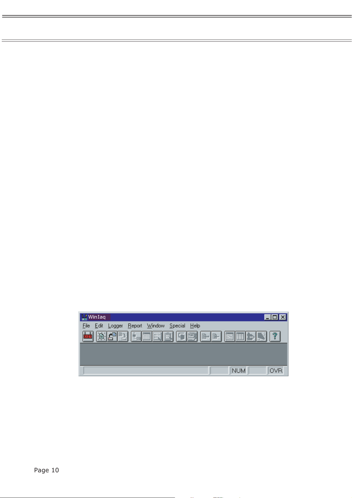
4.3 Starting WinIaq
Start the WinIaq application by double clicking on the icon (Windows 3.1) or
selecting it from the Start Menu (Windows 95).
WinIaq
Once the application has been loaded you are ready to create your first
MICROTHERM profile.
Page 10 of 42
MICROTHERM indoor air quality &
WinIaq Application Software - User Manual
Profiles - Basic
5. MICROTHERM PROFILES - BASIC
All aspects of the operation of an MICROTHERM are determined by the settings
maintained in profiles. Profiles are stored on disk and can be recalled at any
time to allow repetition of previous measuring schemes.
5.1 Creating a New Profile
To create a new profile select File / New from the menu or click on the icon
in the toolbar.
As this is a new profile you will be presented with a series of dialog boxes which
will enable you to define the basic features of this profile.
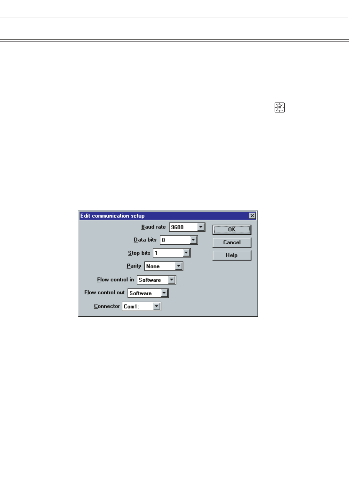
5.2 Defining the Serial Interface
Communication with the MICROTHERM is accomplished using one of the serial
ports available on your computer. In order for this communication to function
correctly both the computer and the MICROTHERM must be set to use the same
protocol. This dialog box enables you to set them.
The default settings in the dialog box match those of a standard MICROTHERM.
The only setting you may need to change is that of the Connector. If a mouse or
other device is already installed on Com1, you will need to change this setting to
another free port.
Note that MICROTHERM control units fitted with internal firmware of V3.30 and
above can be configured to communicate at 9600 baud, all other control units
are limited to a maximum communication speed of 4800 baud.
To determine the version of the firmware fitted in your control unit, scroll the
display to the primary screen. This shows the current baud rate in the bottom
left corner and the current version in the bottom right.
To change the default setting within the MICROTHERM control unit remove the
top panel by unscrewing the four feet. Locate an 8-way dip switch positioned
adjacent to the memory expansion slot. Change the switch settings to match
one of the tables shown:
Page 11 of 42
Profiles - Basic
Versions Prior to V3.30
Baud rate s2 s3
1200 off off
300 off on
2400 on off
4800 on on
Baud rate s2 s3 s5
1200 off off x
9600 off on off
300 off on on
3400 off off x
4800 off on x
MICROTHERM indoor air quality &
WinIaq Application Software - User Manual
Versions V3.3 and Above
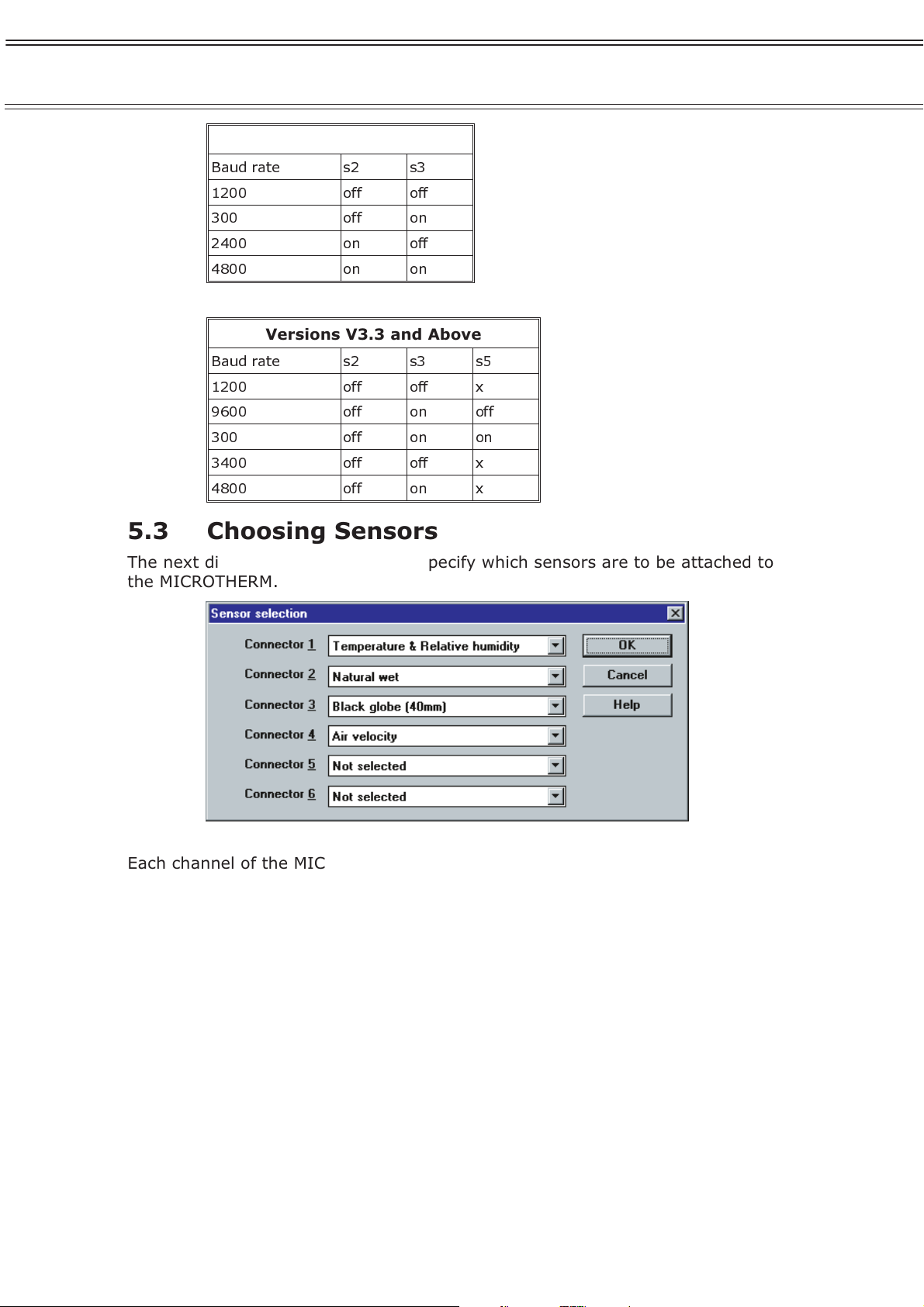
5.3 Choosing Sensors
The next dialog box enables you to specify which sensors are to be attached to
the MICROTHERM.
Each channel of the MICROTHERM can support one or more specific sensors,
make sure you select the correct sensor(s) for each channel and leave any
unused channels as Not selected.
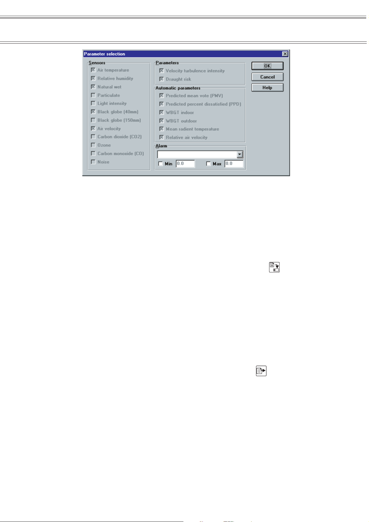
5.4 Parameters
Parameter selection is perfomed automatically by the software. Data from all of
the connected sensors, selected according to Section 5.3, will be measured and
recorded.
The next dialog box (below) shows which sensors and parameters are available.
However to indicate that no further selections can take place, the parameter
fields are “greyed out”. This dialog box has the following three main sections,
detailing the sensors and parameters measured:
Sensors Values recorded directly from the sensors,
Parameters Values calculated within the logger itself,
Automatic Parameters Values calculated by the PC software once the
data is downloaded
Page 12 of 42
MICROTHERM indoor air quality &
WinIaq Application Software - User Manual
Do not worry about the Alarm setting just yet, this will be described in a later
section.
Profiles - Basic
From Sections 1 to 4 you have created a MICROTHERM profile that will record all
available parameters at 10-minute intervals (the default setting).
Changing the default recording interval will be covered later.
Having made a new profile you should save it to disk to make it available for
future use.
To save a profile select File / Save from the menu or click on the icon.
5.5 Transferring Profiles
Before a MICROTHERM can act upon the information stored within a profile, that
profile must be transferred across to the MICROTHERM. Before you attempt to
transfer a profile make sure that:
¤ The MICROTHERM is assembled, connected to mains power and
switched ON.
¤ The serial communication cable is plugged into both the MICROTHERM
and a free serial port on your computer.
Select Logger / Send setup… from the menu or click on the icon.
Having done this, you will be warned that “All data currently stored in the
control unit will be erased”. This is true whenever you transfer a profile to a
MICROTHERM, so make sure that you have recovered the data prior to sending
the profile.
In this instance, we are not interested in the current contents of the
MICROTHERM so can ignore the message.
We can now transfer the profile to the MICROTHERM .
Click on the Send button to start the transfer.
Page 13 of 42
 Loading...