

Casella CEL HB3283-01 User Manual
Side 4
ADVANCED INSTRUMENT SHELTER
User Instructions
7. SERVICING
For UK customers service under guarantee is offered only by the CASELLA CEL Ltd service
department at Regent House, Kempston, Bedford. There are no UK agents or repair services
authorised by us to carry out this work. In order to ensure that only approved replacement parts
are used for routine maintenance after the guarantee period we recommend that this is carried out
by our fully skilled service engineers or in the case of service required outside the UK by our
appointed agents.
CASELLA CEL LIMITED
Regent House
Wolseley Road
Kempston
Bedford
MK42 7JY
Telephone: +44 (0)1234 844100
Facsimile: +44 (0)1234 841490
E-Mail: info@casella.co.uk
Webpage: http://www.casella.co.uk
ADVANCED INSTRUMENT SHELTER
User Instructions
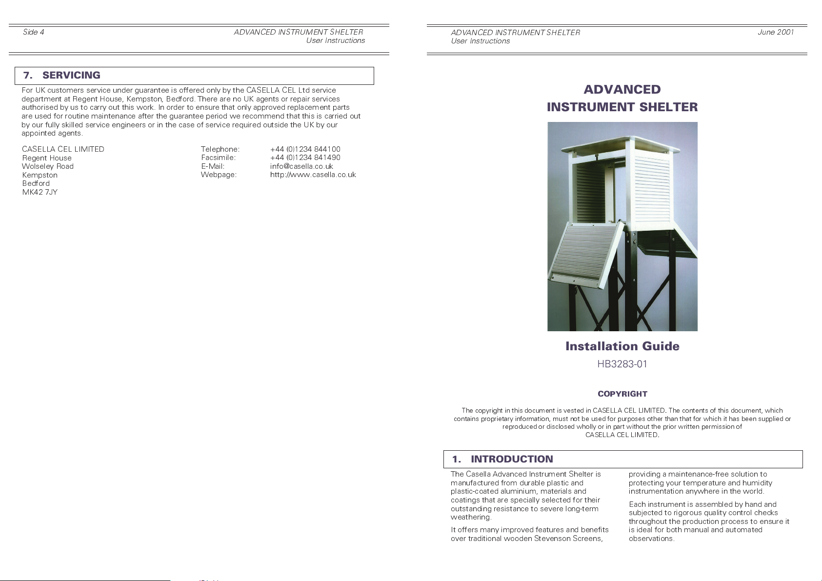
INSTRUMENT SHELTER
June 2001
ADVANCED
Installation Guide
HB3283-01
COPYRIGHT
The copyright in this document is vested in CASELLA CEL LIMITED. The contents of this document, which
contains proprietary information, must not be used for purposes other than that for which it has been supplied or
1. INTRODUCTION
The Casella Advanced Instrument Shelter is
manufactured from durable plastic and
plastic-coated aluminium, materials and
coatings that are specially selected for their
outstanding resistance to severe long-term
weathering.
It offers many improved features and benefits
over traditional wooden Stevenson Screens,
reproduced or disclosed wholly or in part without the prior written permission of
CASELLA CEL LIMITED.
providing a maintenance-free solution to
protecting your temperature and humidity
instrumentation anywhere in the world.
Each instrument is assembled by hand and
subjected to rigorous quality control checks
throughout the production process to ensure it
is ideal for both manual and automated
observations.
Side 2
ADVANCED INSTRUMENT SHELTER
User Instructions
ADVANCED INSTRUMENT SHELTER
User Instructions
Side 3
2. SITING
The temperature measurements used in
meteorology are intended to represent general
conditions over as large an area around the
measuring point as possible. They are usually
taken at a height of 1.25 m above ground level.
To achieve the most representative local
conditions, the measurement station should be
sited in an unobstructed area open to the sun
and wind. Sites sheltered by trees or buildings,
in hollows or on the sides of hills are not
recommended, neither are sites on buildings,
as none of these locations will give
representative measurements.
The Casella Advanced Instrument Shelter is
designed to meet these conditions. It is
supplied with a 1.4 m high stand that must be
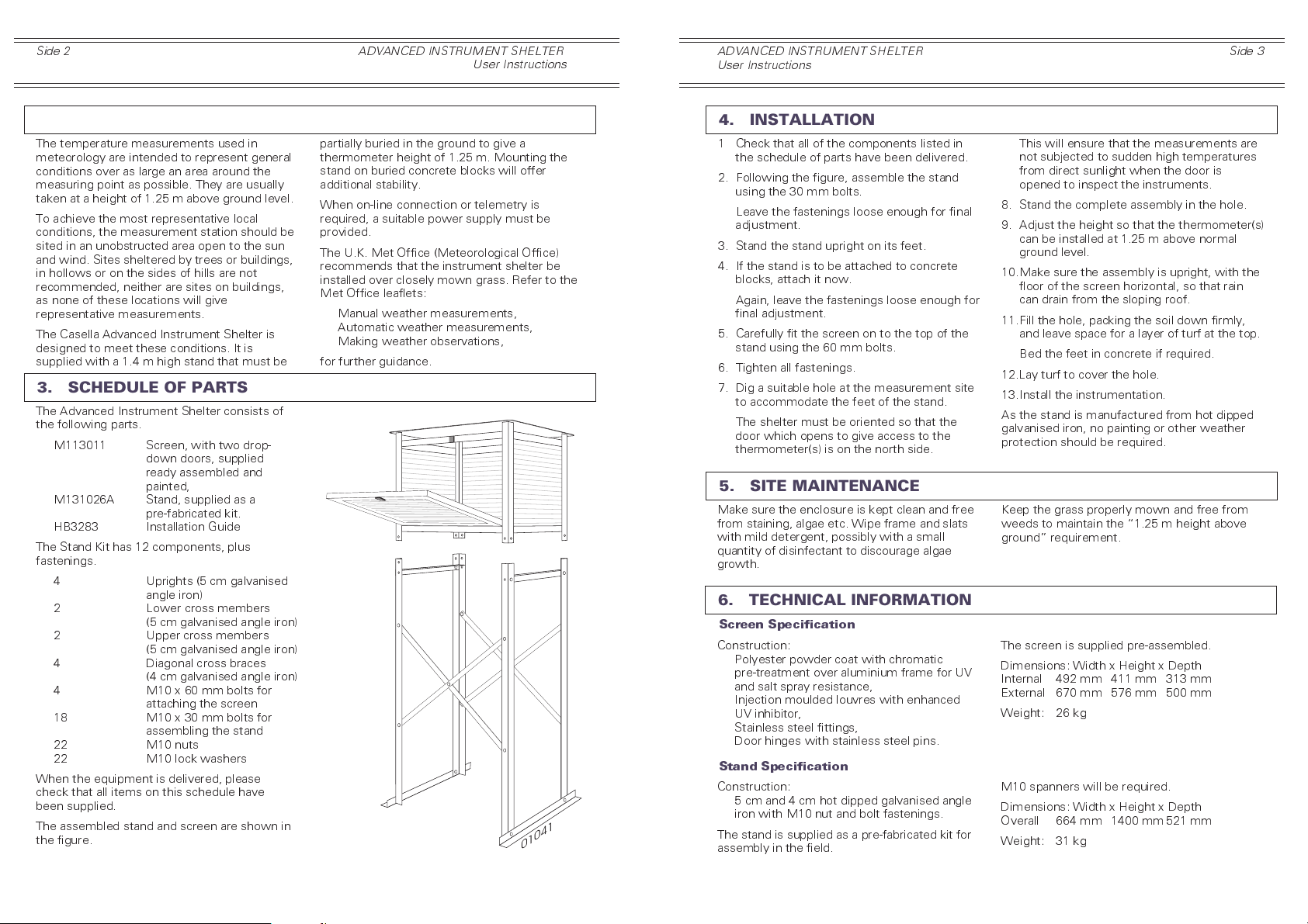
3. SCHEDULE OF PARTS
The Advanced Instrument Shelter consists of
the following parts.
M113011 Screen, with two drop-
down doors, supplied
ready assembled and
painted,
M131026A Stand, supplied as a
pre-fabricated kit.
HB3283 Installation Guide
The Stand Kit has 12 components, plus
fastenings.
4 Uprights (5 cm galvanised
angle iron)
2 Lower cross members
(5 cm galvanised angle iron)
2 Upper cross members
(5 cm galvanised angle iron)
4 Diagonal cross braces
(4 cm galvanised angle iron)
4 M10 x 60 mm bolts for
attaching the screen
18 M10 x 30 mm bolts for
assembling the stand
22 M10 nuts
22 M10 lock washers
When the equipment is delivered, please
check that all items on this schedule have
been supplied.
The assembled stand and screen are shown in
the figure.
partially buried in the ground to give a
thermometer height of 1.25 m. Mounting the
stand on buried concrete blocks will offer
additional stability.
When on-line connection or telemetry is
required, a suitable power supply must be
provided.
The U.K. Met Office (Meteorological Office)
recommends that the instrument shelter be
installed over closely mown grass. Refer to the
Met Office leaflets:
Manual weather measurements,
Automatic weather measurements,
Making weather observations,
for further guidance.
01041
4. INSTALLATION
1 Check that all of the components listed in
the schedule of parts have been delivered.
2. Following the figure, assemble the stand
using the 30 mm bolts.
Leave the fastenings loose enough for final
adjustment.
3. Stand the stand upright on its feet.
4. If the stand is to be attached to concrete
blocks, attach it now.
Again, leave the fastenings loose enough for
final adjustment.
5. Carefully fit the screen on to the top of the
stand using the 60 mm bolts.
6. Tighten all fastenings.
7. Dig a suitable hole at the measurement site
to accommodate the feet of the stand.
The shelter must be oriented so that the
door which opens to give access to the
thermometer(s) is on the north side.
5. SITE MAINTENANCE
Make sure the enclosure is kept clean and free
from staining, algae etc. Wipe frame and slats
with mild detergent, possibly with a small
quantity of disinfectant to discourage algae
growth.
6. TECHNICAL INFORMATION
Screen Specification
Construction:
Polyester powder coat with chromatic
pre-treatment over aluminium frame for UV
and salt spray resistance,
Injection moulded louvres with enhanced
UV inhibitor,
Stainless steel fittings,
Door hinges with stainless steel pins.
Stand Specification
Construction:
5 cm and 4 cm hot dipped galvanised angle
iron with M10 nut and bolt fastenings.
The stand is supplied as a pre-fabricated kit for
assembly in the field.
This will ensure that the measurements are
not subjected to sudden high temperatures
from direct sunlight when the door is
opened to inspect the instruments.
8. Stand the complete assembly in the hole.
9. Adjust the height so that the thermometer(s)
can be installed at 1.25 m above normal
ground level.
10.Make sure the assembly is upright, with the
floor of the screen horizontal, so that rain
can drain from the sloping roof.
11.Fill the hole, packing the soil down firmly,
and leave space for a layer of turf at the top.
Bed the feet in concrete if required.
12.Lay turf to cover the hole.
13.Install the instrumentation.
As the stand is manufactured from hot dipped
galvanised iron, no painting or other weather
protection should be required.
Keep the grass properly mown and free from
weeds to maintain the 1.25 m height above
ground requirement.
The screen is supplied pre-assembled.
Dimensions: Width x Height x Depth
Internal 492 mm 411 mm 313 mm
External 670 mm 576 mm 500 mm
Weight: 26 kg
M10 spanners will be required.
Dimensions: Width x Height x Depth
Overall 664 mm 1400 mm521 mm
Weight: 31 kg
 Loading...