

Casella CEL CEL-490 User Manual
Preparation
DO NOT attempt to power from an external source
without first consulting Section 1.8 of the handbook.
Install 4 x AA size batteries in the compartment in the
underside of the unit.
Screw the Class 1 microphone finger-tight on to the
preamplifier.
Connect the Class 1 preamplifier plus microphone or the
Class 2 microphone/preamplifier assembly by inserting it
into the socket in the top of the instrument case with
the red dot facing the front to ensure correct pin location.
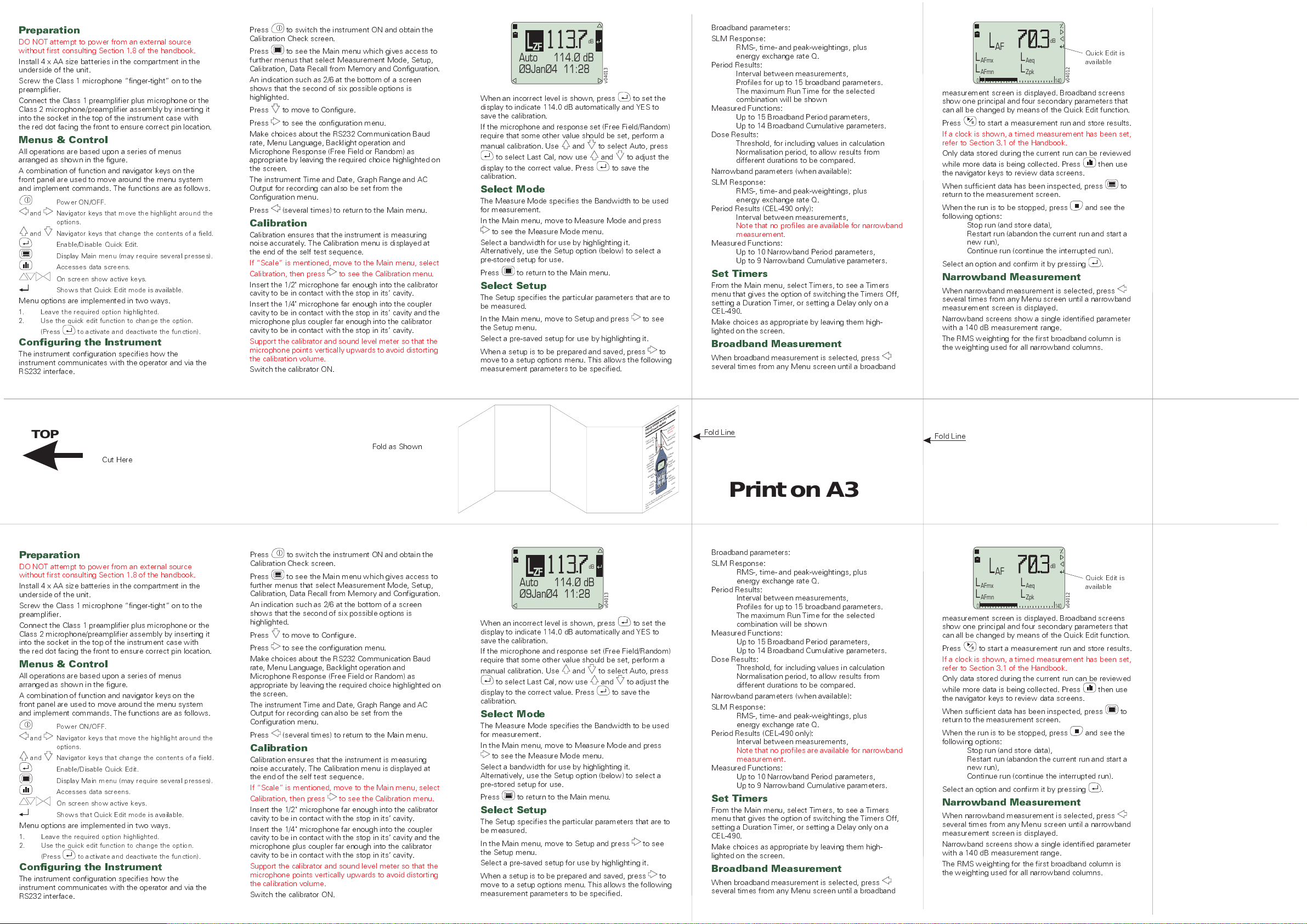
Menus & Control
All operations are based upon a series of menus
arranged as shown in the figure.
A combination of function and navigator keys on the
front panel are used to move around the menu system
and implement commands. The functions are as follows.
Power ON/OFF.
and Navigator keys that move the highlight around the
options.
and Navigator keys that change the contents of a field.
Enable/Disable Quick Edit.
Display Main menu (may require several presses).
Accesses data screens.
On screen show active keys.
Shows that Quick Edit mode is available.
Menu options are implemented in two ways.
1. Leave the required option highlighted.
2. Use the quick edit function to change the option.
(Press to activate and deactivate the function).
Configuring the Instrument
The instrument configuration specifies how the
instrument communicates with the operator and via the
RS232 interface.
Press to switch the instrument ON and obtain the
Calibration Check screen.
Press to see the Main menu which gives access to
further menus that select Measurement Mode, Setup,
Calibration, Data Recall from Memory and Configuration.
An indication such as 2/6 at the bottom of a screen
shows that the second of six possible options is
highlighted.
Press to move to Configure.
Press to see the configuration menu.
Make choices about the RS232 Communication Baud
rate, Menu Language, Backlight operation and
Microphone Response (Free Field or Random) as
appropriate by leaving the required choice highlighted on
the screen.
The instrument Time and Date, Graph Range and AC
Output for recording can also be set from the
Configuration menu.
Press (several times) to return to the Main menu.
Calibration
Calibration ensures that the instrument is measuring
noise accurately. The Calibration menu is displayed at
the end of the self test sequence.
If Scale is mentioned, move to the Main menu, select
Calibration, then press to see the Calibration menu.
Insert the 1/2" microphone far enough into the calibrator
cavity to be in contact with the stop in its cavity.
Insert the 1/4" microphone far enough into the coupler
cavity to be in contact with the stop in its cavity and the
microphone plus coupler far enough into the calibrator
cavity to be in contact with the stop in its cavity.
Support the calibrator and sound level meter so that the
microphone points vertically upwards to avoid distorting
the calibration volume.
Switch the calibrator ON.
L
ZF
dB
114.Ø dBAuto
Ø9JanØ4 11:28
v04013
When an incorrect level is shown, press to set the
display to indicate 114.0 dB automatically and YES to
save the calibration.
If the microphone and response set (Free Field/Random)
require that some other value should be set, perform a
manual calibration. Use and to select Auto, press
to select Last Cal, now use and to adjust the
display to the correct value. Press to save the
calibration.
Select Mode
The Measure Mode specifies the Bandwidth to be used
for measurement.
In the Main menu, move to Measure Mode and press
to see the Measure Mode menu.
Select a bandwidth for use by highlighting it.
Alternatively, use the Setup option (below) to select a
pre-stored setup for use.
Press to return to the Main menu.
Select Setup
The Setup specifies the particular parameters that are to
be measured.
In the Main menu, move to Setup and press to see
the Setup menu.
Select a pre-saved setup for use by highlighting it.
When a setup is to be prepared and saved, press to
move to a setup options menu. This allows the following
measurement parameters to be specified.
Broadband parameters:
SLM Response:
RMS-, time- and peak-weightings, plus
energy exchange rate Q.
Period Results:
Interval between measurements,
Profiles for up to 15 broadband parameters.
The maximum Run Time for the selected
combination will be shown
Measured Functions:
Up to 15 Broadband Period parameters,
Up to 14 Broadband Cumulative parameters.
Dose Results:
Threshold, for including values in calculation
Normalisation period, to allow results from
different durations to be compared.
Narrowband parameters (when available):
SLM Response:
RMS-, time- and peak-weightings, plus
energy exchange rate Q.
Period Results (CEL-490 only):
Interval between measurements,
Note that no profiles are available for narrowband
measurement.
Measured Functions:
Up to 10 Narrowband Period parameters,
Up to 9 Narrowband Cumulative parameters.
Set Timers
From the Main menu, select Timers, to see a Timers
menu that gives the option of switching the Timers Off,
setting a Duration Timer, or setting a Delay only on a
CEL-490.
Make choices as appropriate by leaving them high-
lighted on the screen.
Broadband Measurement
When broadband measurement is selected, press
several times from any Menu screen until a broadband
L
AF
L
AFmx
LL
AFmn Zpk
0140
measurement screen is displayed. Broadband screens
show one principal and four secondary parameters that
can all be changed by means of the Quick Edit function.
dB
v04012
Quick Edit is
available
L
Aeq
Press to start a measurement run and store results.
If a clock is shown, a timed measurement has been set,
refer to Section 3.1 of the Handbook.
Only data stored during the current run can be reviewed
while more data is being collected. Press then use
the navigator keys to review data screens.
When sufficient data has been inspected, press to
return to the measurement screen.
When the run is to be stopped, press and see the
following options:
Stop run (and store data),
Restart run (abandon the current run and start a
new run),
Continue run (continue the interrupted run).
Select an option and confirm it by pressing .
Narrowband Measurement
When narrowband measurement is selected, press
several times from any Menu screen until a narrowband
measurement screen is displayed.
Narrowband screens show a single identified parameter
with a 140 dB measurement range.
The RMS weighting for the first broadband column is
the weighting used for all narrowband columns.
TOP
Cut Here
Preparation
DO NOT attempt to power from an external source
without first consulting Section 1.8 of the handbook.
Install 4 x AA size batteries in the compartment in the
underside of the unit.
Screw the Class 1 microphone finger-tight on to the
preamplifier.
Connect the Class 1 preamplifier plus microphone or the
Class 2 microphone/preamplifier assembly by inserting it
into the socket in the top of the instrument case with
the red dot facing the front to ensure correct pin location.
Menus & Control
All operations are based upon a series of menus
arranged as shown in the figure.
A combination of function and navigator keys on the
front panel are used to move around the menu system
and implement commands. The functions are as follows.
Power ON/OFF.
and Navigator keys that move the highlight around the
options.
and Navigator keys that change the contents of a field.
Enable/Disable Quick Edit.
Display Main menu (may require several presses).
Accesses data screens.
On screen show active keys.
Menu options are implemented in two ways.
1. Leave the required option highlighted.
2. Use the quick edit function to change the option.
Configuring the Instrument
The instrument configuration specifies how the
instrument communicates with the operator and via the
RS232 interface.
Shows that Quick Edit mode is available.
(Press to activate and deactivate the function).
Fold as Shown
Press to switch the instrument ON and obtain the
Calibration Check screen.
Press to see the Main menu which gives access to
further menus that select Measurement Mode, Setup,
Calibration, Data Recall from Memory and Configuration.
An indication such as 2/6 at the bottom of a screen
shows that the second of six possible options is
highlighted.
Press to move to Configure.
Press to see the configuration menu.
Make choices about the RS232 Communication Baud
rate, Menu Language, Backlight operation and
Microphone Response (Free Field or Random) as
appropriate by leaving the required choice highlighted on
the screen.
The instrument Time and Date, Graph Range and AC
Output for recording can also be set from the
Configuration menu.
Press (several times) to return to the Main menu.
Calibration
Calibration ensures that the instrument is measuring
noise accurately. The Calibration menu is displayed at
the end of the self test sequence.
If Scale is mentioned, move to the Main menu, select
Calibration, then press to see the Calibration menu.
Insert the 1/2" microphone far enough into the calibrator
cavity to be in contact with the stop in its cavity.
Insert the 1/4" microphone far enough into the coupler
cavity to be in contact with the stop in its cavity and the
microphone plus coupler far enough into the calibrator
cavity to be in contact with the stop in its cavity.
Support the calibrator and sound level meter so that the
microphone points vertically upwards to avoid distorting
the calibration volume.
Switch the calibrator ON.
FIELD GUIDEto CEL-450/490
Sound LevelMeters
Class2, 1/4"
&
Microphone
Preamplifier
Pull the
knurled
sleeve
outwardsto
releasethe
connector
ON/OFF
Navigator
keys
Start/
Pause/
Restart
Access
data
TheCEL-450 andCEL-490Sound Level Meters consist
ofthe instrumentunitpreamplifier andmicrophone
shown.
L
ZF
dB
114.Ø dBAuto
Ø9JanØ4 11:28
v04013
When an incorrect level is shown, press to set the
display to indicate 114.0 dB automatically and YES to
save the calibration.
If the microphone and response set (Free Field/Random)
require that some other value should be set, perform a
manual calibration. Use and to select Auto, press
to select Last Cal, now use and to adjust the
display to the correct value. Press to save the
calibration.
Select Mode
The Measure Mode specifies the Bandwidth to be used
for measurement.
In the Main menu, move to Measure Mode and press
to see the Measure Mode menu.
Select a bandwidth for use by highlighting it.
Alternatively, use the Setup option (below) to select a
pre-stored setup for use.
Press to return to the Main menu.
Select Setup
The Setup specifies the particular parameters that are to
be measured.
In the Main menu, move to Setup and press to see
the Setup menu.
Select a pre-saved setup for use by highlighting it.
When a setup is to be prepared and saved, press to
move to a setup options menu. This allows the following
measurement parameters to be specified.
Protective
grill (
remove
Class1, 1/2"
Microphone
Preamplifier
Reddot
Change
menu
Enable
Quickedit/
Select
Backlight
Stop
(needs
toconfirm)
donot
)
Fold Line
v04003
Fold Line
Print on A3
Broadband parameters:
SLM Response:
RMS-, time- and peak-weightings, plus
energy exchange rate Q.
Period Results:
Interval between measurements,
Profiles for up to 15 broadband parameters.
The maximum Run Time for the selected
combination will be shown
Measured Functions:
Up to 15 Broadband Period parameters,
Up to 14 Broadband Cumulative parameters.
Dose Results:
Threshold, for including values in calculation
Normalisation period, to allow results from
different durations to be compared.
Narrowband parameters (when available):
SLM Response:
RMS-, time- and peak-weightings, plus
energy exchange rate Q.
Period Results (CEL-490 only):
Interval between measurements,
Note that no profiles are available for narrowband
measurement.
Measured Functions:
Up to 10 Narrowband Period parameters,
Up to 9 Narrowband Cumulative parameters.
Set Timers
From the Main menu, select Timers, to see a Timers
menu that gives the option of switching the Timers Off,
setting a Duration Timer, or setting a Delay only on a
CEL-490.
Make choices as appropriate by leaving them high-
lighted on the screen.
Broadband Measurement
When broadband measurement is selected, press
several times from any Menu screen until a broadband
L
AF
L
AFmx
LL
AFmn Zpk
0140
measurement screen is displayed. Broadband screens
show one principal and four secondary parameters that
can all be changed by means of the Quick Edit function.
Press to start a measurement run and store results.
If a clock is shown, a timed measurement has been set,
refer to Section 3.1 of the Handbook.
Only data stored during the current run can be reviewed
while more data is being collected. Press then use
the navigator keys to review data screens.
When sufficient data has been inspected, press to
return to the measurement screen.
When the run is to be stopped, press and see the
following options:
Stop run (and store data),
Restart run (abandon the current run and start a
new run),
Continue run (continue the interrupted run).
Select an option and confirm it by pressing .
Narrowband Measurement
When narrowband measurement is selected, press
several times from any Menu screen until a narrowband
measurement screen is displayed.
Narrowband screens show a single identified parameter
with a 140 dB measurement range.
The RMS weighting for the first broadband column is
the weighting used for all narrowband columns.
dB
v04012
Quick Edit is
available
L
Aeq
L
Z
I
ACZ
Z 73.6
2506316
120
80
40
Before or during a narrowband run, use and to
obtain levels from the individual frequency bands of the
displayed parameter.
dB
1k
16k
4k
V04014
Press to start a run and store results.
If a clock is shown, a timed measurement has been set,
refer to Section 3.1 of the Handbook.
Once a run has started, can be used to activate
Quick Edit. Now and select the other measured
parameters. In addition, if the measurement range is
selected, and can be used to change the span
and offset, and if the frequency range is selected, the
frequency range can be limited.
Remember to reset the 140 dB range after use.
Press then use the navigator keys to review the
data screens. Only data stored during the current run
can be reviewed while more data is being collected.
When sufficient data has been inspected, press to
return to the measurement screen.
When the run is to be stopped, press and see the
following options:
Stop run (and store data),
Restart run (abandon current run and start a
new run),
Continue run (continue interrupted run).
Select an option and confirm it by pressing .
Cel 490
CASELLA CEL Ltd, 2004
CEL49Ø.C1 vNN.NN
8Ø - 19ØØ28A - NN
Preamp
I/O
ID:
13JanØ4 1Ø:54:42
2Mb
2
1%
Format
Setup
User Setup 1
Press MENU
Key to Start
Calibrate
L
ZF
114.ØdBAuto
Ø9JanØ4 11:28
Measure
Type 1
None
NNNNNN
Memory
Runs
Full
dB
Broadband
Narrowband
Instrument
Version:
A=Broadband
XX
B=Octave
XX
C=Third-octave
XX
Type1or2
Firmware version
Program and version
Instrument ID
Measure Mode
Setup
Calibration
Timers
2/7
Memory
Configure
Status
Obtain Menu
L
AF
L
L
AFmx
Aeq
LL
AFmn Zpk
0 140
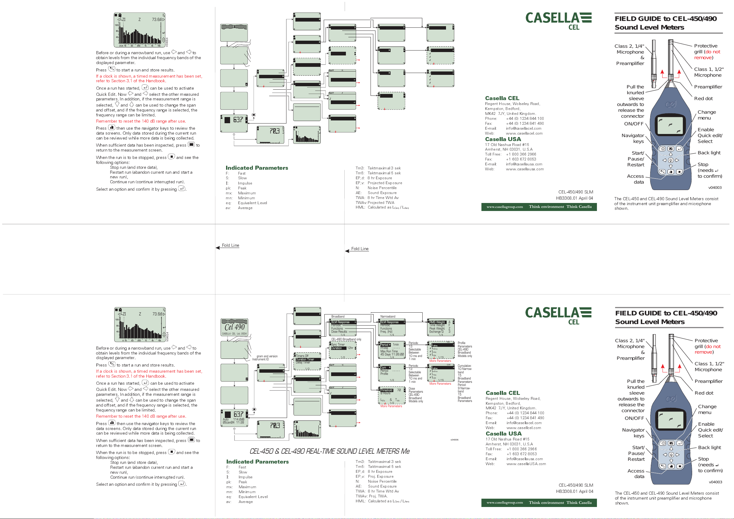
CEL-450 & CEL-490 REAL-TIME SOUND LEVEL METERS Menu Structure
Indicated Parameters
F: Fast
S: Slow
I
: Impulse
pk: Peak
mx: Maximum
mn: Minimum
eq: Equivalent Level
av: Average
dB
Broadband
Octave
Third Octave
2/3
Factory Setup
User Setup 1
User Setup 2
User Setup 3
2/5
User Setup 4
Timers Off
Duration Timer
Delay Timer
1/3
View Current
View All
Delete Current
Delete All
1/4
13JanØ4 1Ø:54:42
512Kb
Memory
Full
1%
Runs
2
L
ZIZ84.6
120
80
40
ACZ
1k
2506316
4k
Broadband
SLM Response SLM Response
Periodic Periodic
Functions Functions
Dose Results Freq. (Hz)
1/4 1/4
CEL-490 Broadband only
Sync Timer
Duration
12hr
More
Options
Runs
Runs
More
Options
Tm3: Taktmaximal 3 sek
Tm5: Taktmaximal 5 sek
EP,d: 8 hr Exposure
EP,v: Projected Exposure
N: Noise Percentile
AE: Sound Exposure
TWA: 8 hr Time Wtd Av
TWAv:Projected TWA
HML: Calculated as L
dB
dB
16k Hz
1/2
Wed 7 Jan2ØØ4
9 Jan2ØØ4
Fri
13 Jan2ØØ4
Tue
15 Jan2ØØ4
Thu
1
3
Wed 7 Jan2ØØ4
9 Jan2ØØ4
Fri
13 Jan2ØØ4
Tue
15 Jan2ØØ4
Thu
RS232 Comms
Language
Backlight
Graph Range
1/7
Time&Date
Microphone
AC Output
Narrowband
-----
7Ø
T&
Ceq/LAeq
Periods:
13
Selectable
Between
10 ms and
1min
Periods:
13
Selectable
Between
10 ms and
1min
Dose
Parameters
CEL-490
Broadband
Models only
Period 1min
Profile ----Max Run Time
45 Days 11:26:ØØ
1/4
Profile
1/2 1/15
Threshold
8 Hours
EP,dLWA
1/2
More Parameters
RMS Weight A
Time Weight F
Peak Weight Z
Exchange Q 3
1/4
PER
L
AFmx
LL
AFmn
L
L
Aeq
LL
Zpk
1/15
More Parameters
CUM
LCum L
AFmx
LPeriod
L
AFmn
L
L
Aeq
LL
Zpk
More Parameters
v04006
Profile
Parameters
CEL-490
Broadband
Models only
Cumulative:
10 Narrowband
15
Broadband
Parameters
Period:
9 Narrowband
15
Broadband
Parameters
Casella CEL
Regent House, Wolseley Road,
Kempston, Bedford,
MK42 7JY, United Kingdom.
Phone: +44 (0) 1234 844 100
Fax: +44 (0) 1234 841 490
E-mail: info@casellacel.com
Web: www.casellacel.com
Casella USA
17 Old Nashua Road #15
Amherst, NH 03031, U.S.A
Toll Free: +1 800 366 2966
Fax: +1 603 672 8053
E-mail: info@casellausa.com
Web: www.casellausa.com
www.casellagroup.com
Think environment Think Casella
CEL-450/490 SLM
HB3308.01 April 04
FIELD GUIDE to CEL-450/490
Sound Level Meters
Class 2, 1/4"
Microphone
&
Preamplifier
Pull the
knurled
sleeve
outwards to
release the
connector
ON/OFF
Navigator
keys
Start/
Pause/
Restart
Access
data
The CEL-450 and CEL-490 Sound Level Meters consist
of the instrument unit preamplifier and microphone
shown.
Protective
do not
grill (
remove
)
Class 1, 1/2"
Microphone
Preamplifier
Red dot
Change
menu
Enable
Quick edit/
Select
Back light
Stop
(needs
to confirm)
v04003
L
Z
I
ACZ
Z 73.6
2506316
120
80
40
Before or during a narrowband run, use and to
obtain levels from the individual frequency bands of the
displayed parameter.
dB
1k
16k
4k
V04014
Press to start a run and store results.
If a clock is shown, a timed measurement has been set,
refer to Section 3.1 of the Handbook.
Once a run has started, can be used to activate
Quick Edit. Now and select the other measured
parameters. In addition, if the measurement range is
selected, and can be used to change the span
and offset, and if the frequency range is selected, the
frequency range can be limited.
Remember to reset the 140 dB range after use.
Press then use the navigator keys to review the
data screens. Only data stored during the current run
can be reviewed while more data is being collected.
When sufficient data has been inspected, press to
return to the measurement screen.
When the run is to be stopped, press and see the
following options:
Stop run (and store data),
Restart run (abandon current run and start a
new run),
Continue run (continue interrupted run).
Select an option and confirm it by pressing .
Fold Line
Cel 490
CASELLA CEL Ltd, 2004
CEL49Ø.C1 vNN.NN
8Ø - 19ØØ28A - NN
Preamp
I/O
ID:
13JanØ4 1Ø:54:42
2Mb
2
1%
Format
Setup
User Setup 1
Press MENU
Key to Start
Calibrate
L
ZF
114.ØdBAuto
Ø9JanØ4 11:28
Measure
Type 1
None
NNNNNN
Memory
Runs
Full
dB
Broadband
Narrowband
Instrument
Version:
A=Broadband
XX
B=Octave
XX
C=Third-octave
XX
Type1or2
Firmware version
Program and version
Instrument ID
Measure Mode
Setup
Calibration
Timers
2/7
Memory
Configure
Status
Obtain Menu
L
AF
L
L
AFmx
Aeq
LL
AFmn Zpk
0 140
CEL-450 & CEL-490 REAL-TIME SOUND LEVEL METERS Menu Structure
Indicated Parameters
F: Fast
S: Slow
I
: Impulse
pk: Peak
mx: Maximum
mn: Minimum
eq: Equivalent Level
av: Average
dB
Broadband
Octave
Third Octave
2/3
Factory Setup
User Setup 1
User Setup 2
User Setup 3
2/5
User Setup 4
Timers Off
Duration Timer
Delay Timer
1/3
View Current
View All
Delete Current
Delete All
1/4
13JanØ4 1Ø:54:42
512Kb
Memory
1%
Full
2
Runs
L
ZIZ84.6
120
80
40
ACZ
1k
2506316
4k
Fold Line
Broadband
SLM Response SLM Response
Periodic Periodic
Functions Functions
Dose Results Freq. (Hz)
1/4 1/4
CEL-490 Broadband only
Sync Timer
Duration
12hr
More
Options
Runs
Runs
More
Options
Tm3: Taktmaximal 3 sek
Tm5: Taktmaximal 5 sek
EP,d: 8 hr Exposure
EP,v: Proj. Exposure
N: Noise Percentile
AE: Sound Exposure
TWA: 8 hr Time Wtd Av
TWAv: Proj. TWA.
HML: Calculated as L
dB
dB
16k Hz
1/2
Wed 7 Jan2ØØ4
9 Jan2ØØ4
Fri
13 Jan2ØØ4
Tue
15 Jan2ØØ4
Thu
1
3
Wed 7 Jan2ØØ4
Fri
9 Jan2ØØ4
13 Jan2ØØ4
Tue
15 Jan2ØØ4
Thu
RS232 Comms
Language
Backlight
Graph Range
1/7
Time&Date
Microphone
AC Output
Narrowband
-----
7Ø
T&
Ceq/LAeq
Periods:
13
Selectable
Between
10 ms and
1min
Periods:
13
Selectable
Between
10 ms and
1min
Dose
Parameters
CEL-490
Broadband
Models only
Period 1min
Profile ----Max Run Time
45 Days 11:26:ØØ
1/4
Profile
1/2 1/15
Threshold
8 Hours
EP,dLWA
1/2
More Parameters
RMS Weight A
Time Weight F
Peak Weight Z
Exchange Q 3
1/4
PER
L
AFmx
LL
AFmn
L
L
Aeq
LL
Zpk
1/15
More Parameters
CUM
LCum L
AFmx
LPeriod
L
AFmn
L
L
Aeq
LL
Zpk
More Parameters
v04006
Profile
Parameters
CEL-490
Broadband
Models only
Cumulative:
10 Narrowband
15
Broadband
Parameters
Period:
9 Narrowband
15
Broadband
Parameters
Casella CEL
Regent House, Wolseley Road,
Kempston, Bedford,
MK42 7JY, United Kingdom.
Phone: +44 (0) 1234 844 100
Fax: +44 (0) 1234 841 490
E-mail: info@casellacel.com
Web: www.casellcel.com
Casella USA
17 Old Nashua Road #15
Amherst, NH 03031, U.S.A
Toll Free: +1 800 366 2966
Fax: +1 603 672 8053
E-mail: info@casellausa.com
Web: www.casellaUSA.com
www.casellagroup.com
Think environment Think Casella
CEL-450/490 SLM
HB3308.01 April 04
FIELD GUIDE to CEL-450/490
Sound Level Meters
Class 2, 1/4"
Microphone
&
Preamplifier
Pull the
knurled
sleeve
outwards to
release the
connector
ON/OFF
Navigator
keys
Start/
Pause/
Restart
Access
data
The CEL-450 and CEL-490 Sound Level Meters consist
of the instrument unit preamplifier and microphone
shown.
Protective
grill (
do not
)
remove
Class 1, 1/2"
Microphone
Preamplifier
Red dot
Change
menu
Enable
Quick edit/
Select
Back light
Stop
(needs
to confirm)
v04003
 Loading...