

Casella CEL CEL-414 User Manual
SOUND LEVEL METERS
CEL-266/3, CEL-275/3, CEL-414/3
CEL-493/3 - Type 1
CEL-328/3, & CEL-383/3 - Type 2
Operator’s Handbook
Document 060174
Issue: 1C
February 1996
Compliance
The CEL-266/3A, CEL-328/3A, CEL-383/3A & /3B, CEL-275/3A & /3B and CEL-414/3 Sound
Level Meters comply with the EMC Directive 89/336/EEC of the European Union.
They have been tested according to the standard delivery schedule and comply with the fol-
lowing standards.
EN 50081-1 : 1992
EN 50081-2 : 1993Generic emission standards for residential, commercial, light
industry and industrial environments.
EN 50082-1 : 1992
EN 50082-2 : 1993Generic immunity standards (for both RF fields and electrostatic
discharge) for residential, commercial, light industry and industrial
environments.
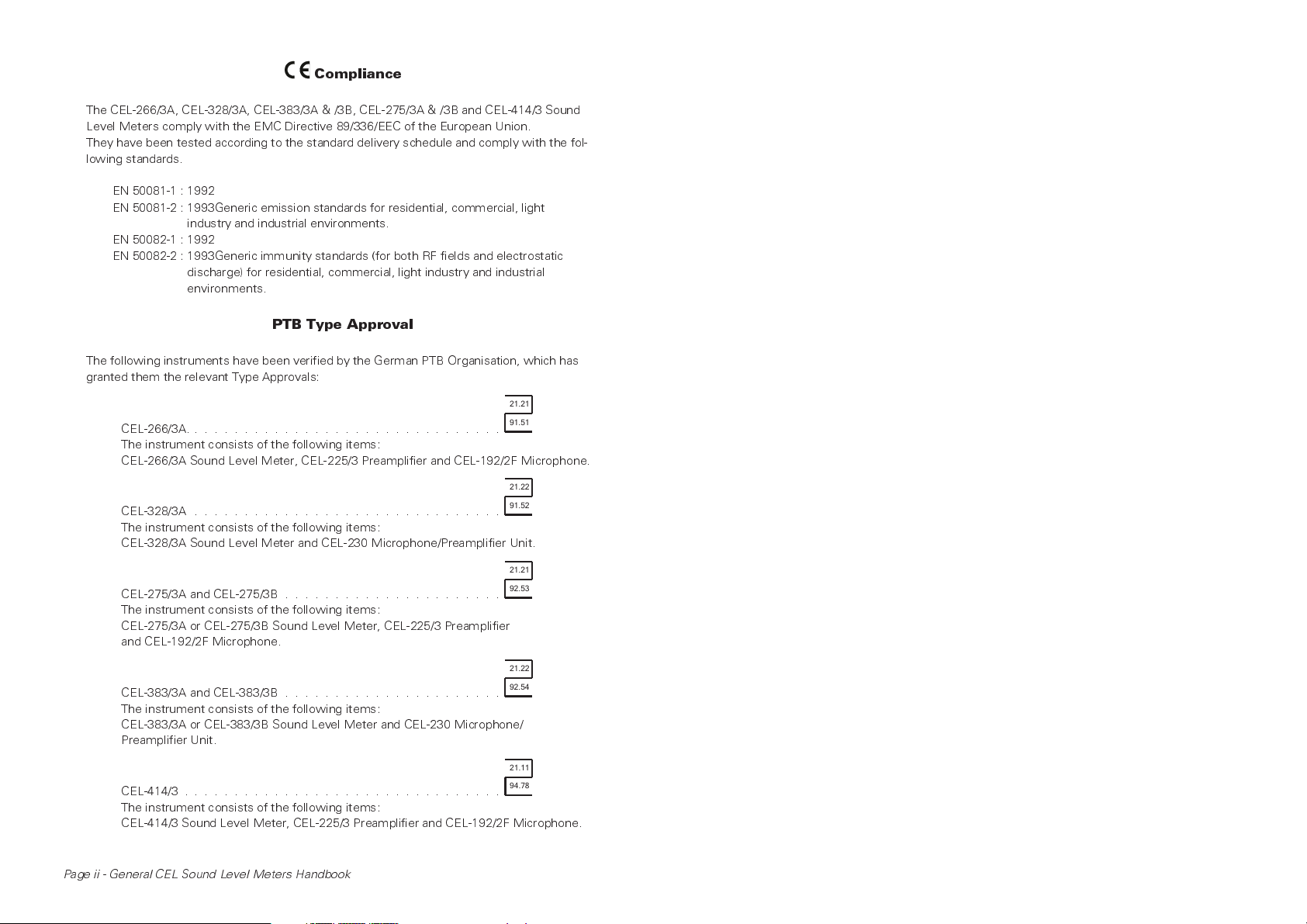
PTB Type Approval
The following instruments have been verified by the German PTB Organisation, which has
granted them the relevant Type Approvals:
21.21
CEL-266/3A. ...............................
The instrument consists of the following items:
CEL-266/3A Sound Level Meter, CEL-225/3 Preamplifier and CEL-192/2F Microphone.
CEL-328/3A ...............................
The instrument consists of the following items:
CEL-328/3A Sound Level Meter and CEL-230 Microphone/Preamplifier Unit.
CEL-275/3A and CEL-275/3B ......................
The instrument consists of the following items:
CEL-275/3A or CEL-275/3B Sound Level Meter, CEL-225/3 Preamplifier
and CEL-192/2F Microphone.
CEL-383/3A and CEL-383/3B ......................
The instrument consists of the following items:
CEL-383/3A or CEL-383/3B Sound Level Meter and CEL-230 Microphone/
Preamplifier Unit.
CEL-414/3 ................................
The instrument consists of the following items:
CEL-414/3 Sound Level Meter, CEL-225/3 Preamplifier and CEL-192/2F Microphone.
91.51
21.22
91.52
21.21
92.53
21.22
92.54
21.11
94.78
Page ii - General CEL Sound Level Meters Handbook
Contents Page
1. INTRODUCTION ..........................1
2. SCHEDULE OF PARTS ......................3
3. DESCRIPTION ...........................4
3.1 Technical Description ....................4
3.2 Control Facilities ......................9
3.3 General Reset ......................11
3.4 Display ..........................12
3.5 Auxiliary Outputs .....................13
3.6 Auxiliary Inputs ......................14
3.7 Octave Filters .......................14
3.8 Batteries & Auxiliary Power Supplies ..........15
4. PREPARATION FOR USE ....................16
4.1 Battery Installation ....................16
4.2 Fitting Microphones & Preamplifiers ...........17
5. FIELD ACCURACY CHECK (ACOUSTIC CALIBRATION) ....18
6. OPERATION ...........................20
6.1 General Procedures ...................21
6.2 Measurement of Sound Pressure Level - SPL ......22
6.3 Measurement of One Second Mode - 1SM
(not CEL-266/3, CEL-328/3 or CEL-414/3) ........22
6.4 Duration of Measurement Period - DUR .........23
6.5 Measurement of Maximum Value - L
6.6 Measurement of Equivalent Continuous Level - L
(not CEL-414/3 or CEL-328/3C) ..............23
6.7 Measurement of Sound Exposure Level - SEL
(not CEL-266/3, CEL-328/3 or CEL-414/3) ........24
6.7.1 Event Times Determined by Threshold Level
(only CEL-493/3) .....................24
6.7.2 Events Timed Manually
(not CEL-266/3, CEL-328/3 or CEL-414/3) ........25
6.8 Measurement of 3 & 5s Cumulative Average - L
L
(A, B and CEL-493/3) ................26
Tm5
6.9 Measurement of L
OSHA&LDOD
(C & D versions) ....26
6.9.1 Setting the Threshold Level ...............26
6.9.2 L
OSHA&LDOD
Measurement ...............27
6.10 Frequency Analysis Using Built-in Octave Filters
(only CEL-266/3 & CEL-328/3) ..............27
........23
max
Tm3
eq
&
General CEL Sound Level Meters Handbook - Page iii
Contents Page
7. USE WITH OTHER EQUIPMENT ................ 28
7.1 Frequency Analysis With External Filter Sets
(not CEL-266/3 or CEL-328/3) .............. 28
7.2 Use With CEL-3025 Vibration Attachment Kit ..... 28
7.3 Recording With CEL-238A, CEL-338, & CEL-438
Digital Recorders & Analysers (B, D & CEL-493/3) . . . 29
7.4 Use With Tape Recorders ................ 30
7.4.1 Recording With a Tape Recorder ............ 31
7.4.2 Replay From a Tape Recorder .............. 33
7.5 Graphic Level Recorders ................ 34
8. DIGITAL INTERFACE (B & D, and CEL-493/3 only) ...... 35
9. EXPLANATION OF TERMS USED ............... 38
9.1 Sound Pressure Level (SPL) ............... 38
9.2 Duration of Measurement Period (DUR) ........ 39
9.3 Equivalent Continuous Noise Levels (L
9.4 Sound Exposure Level (SEL or L
9.5 Maximum Value (
L
)
.................. 41
max
9.6 PeakMaximumValue.................. 41
9.7 3 & 5s Cumulative Average Values
9.8 L
(L
Tm3<m5
OSHA&LDOD
- A, B Versions & CEL-493/3) ...... 41
(C & D Versions) ............. 42
)........ 39
eq
)........... 40
AE
10. POST PRODUCTION DEVELOPMENTS ............ 42
10.1 Digital Interface for A & C Versions ........... 42
10.2 1SM Measurement Link ................. 42
11. SPECIFICATION ........................ 43
12. ERROR MESSAGES ...................... 48
13. MANUFACTURERS SERVICING & WARRANTY ....... 49
14. PTB TYPE APPROVAL ..................... 50
Page iv - General CEL Sound Level Meters Handbook
1. INTRODUCTION
These instruments are a re-interpretation
of the classic full specification sound
level meter.
The CEL-266/3, CEL-275/3, CEL-414/3
and CEL-493/3 satisfy the requirements
of IEC 651: 1971 Type 1Ifor precision
impulse sound level meters (and ANSI:
S1.4-1983, Type S1 when used with an
R type random incidence microphone).
The CEL-266/3, CEL-275/3 and CEL-
493/3 also satisfy the requirements of
IEC 804 Type 1 for integrating sound
level meters.
The CEL-328/3 and CEL-383/3 satisfy the
requirements of IEC 651: 1971 Type 2
I
for impulse sound level meters, ANSI:
S1.4-1983, Type S2 for sound level me-
ters and (except for CEL-328/3E) also IEC
804 Type 2 for integrating sound level
meters.
All of these instruments and versions can
measure sound pressure levels in the
range from 20 dB(A) to 140 dB(A) at fre-
quencies between 3.5 Hz and 20 kHz
with the microphone supplied, and up to
70 kHz with a suitable microphone.
When used with the CEL-4391 Attenu-
ator Pad (supplied) the CEL-493/3 is able
to measure sound levels up to 150 dB(A).
The instruments use modern microproc-
essor and component integration to pro-
viding all the traditional measurement
facilities in a compact and easily handled
unit.
Well proven concepts and methods have
been employed in their design and con-
struction so that the most commonly
used acoustic measurements can be per-
formed. They provide a continuous indica-
tion of the instantaneous sound pressure
level SPL in both analog and digital for-
mats on a liquid crystal display. Displays
showing the measurement duration and
maximum value may also be selected.
The CEL-266/3 and CEL-328/3 contain 10
built-in octave filters with centre frequen-
cies between 31.5 Hz and 16 kHz. These
filters satisfy the requirements of IEC
225 and ANSI S1.11-R1975 Class 2.
With the exception of the CEL-414/3 and
the CEL-328/3E, all versions also calcu-
late the equivalent continuous level L
(plus L
Tm3
and L
Tm5
,orL
OSHA
and L
DOD
eq
)
and the sound exposure level SEL at the
same time. The CEL-328/3E calculates
only the octave filtered L
eq
values.
This Operators Handbook covers all of
the instrument types and versions shown
below.
CEL
Type
328/3
Type 2
383/3
Type 2
266/3
Type 1
275/3
Type 1
414/3
Type 1
493/3
Type 1
European
Versions
Oct.
AB
Filter
XX X X
XX X
One single version, with European
software plus a built-in interface
I/face
XXXX
XXXX
American
Versions
CD
I/face
X
E
The CEL-493/3 plus B and D instrument
versions have a built-in CEL low power
interface, which allows them to be con-
nected to one of the data logger/printers
General CEL Sound Level Meters Handbook - Page 1
in the CEL-438, CEL-338 and CEL-238A
series, or to some other digital device for
data logging or processing, and for con-
trol purposes.
D Standard American version (as C)
that contains a CEL low power serial
interface,
E (CEL-328/3 only) Non-integrating
version based on the CEL-328/3C,
With the exception of the CEL-414/3C
which has no integration functions, these
instruments have the following features:
without L
L
All instruments and versions have a simi-
eq
OSHA,LDOD
.
lar appearance, with minor differences
A Standard European version of the
instrument measuring SPL, L
L
Tm3,LTm5Lmax
, SEL, (and 1SM),
,
eq
with A-weighted and Linear
frequency response,
B Standard European version (as A)
that contains a CEL low power serial
interface,
C Standard American version of the
instrument measuring SPL, L
L
OSHA,LDOD,Lmax
SEL, (and 1SM),
,
eq
with A- and C-weighted frequency
response,
only in the legends on the frequency
weighting switch and on the bezel sur-
rounding the main display. The best way
to identify an instrument version is to re-
fer to the suffix letter in the instrument
serial number on the rear cover, or to
note the version letter (A, C or E in upper
case, b or d in lower case) displayed to-
gether with the type number during the
instruments start up sequence.
All versions will accept the CEL-3025 Vi-
bration Attachment connected via the
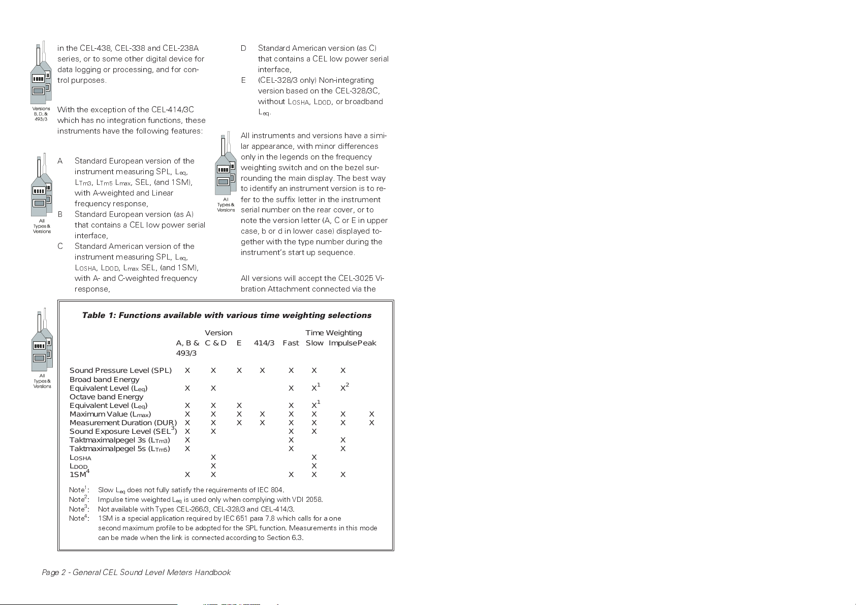
Table 1: Functions available with various time weighting selections
Version Time Weighting
A, B & C & D E 414/3 Fast Slow ImpulsePeak
493/3
, or broadband
Sound Pressure Level (SPL) X X X X X X X
Broad band Energy
Equivalent Level (L
Octave band Energy
Equivalent Level (L
Maximum Value (L
Measurement Duration (DUR) X X X X X X X X
Sound Exposure Level (SEL
Taktmaximalpegel 3s (L
Taktmaximalpegel 5s (L
L
OSHA
L
DOD
4
1SM
Note1: Slow Leqdoes not fully satisfy the requirements of IEC 804.
2
: Impulse time weighted Leqis used only when complying with VDI 2058.
Note
3
: Not available with Types CEL-266/3, CEL-328/3 and CEL-414/3.
Note
4
: 1SM is a special application required by IEC 651 para 7.8 which calls for a one
Note
second maximum profile to be adopted for the SPL function. Measurements in this mode
can be made when the link is connected according to Section 6.3.
)XX XX1X
eq
) XXX XX
eq
) XXXXXXXX
max
3
)X X X X
)X X X
Tm3
)X X X
Tm5
XX
XX
XX XX X
Page 2 - General CEL Sound Level Meters Handbook
2
1
CEL-225/3* (supplied only with Type 1
instruments) or the earlier CEL-225 Pre-
amplifier so that vibration levels can be
measured.
The built-in octave filters of the CEL-
266/3 and CEL-328/3 can be used for fre-
quency analysis of both noise and
vibration. Frequency analysis can also be
performed by the CEL-275/3, CEL-383/3,
CEL-414/3 and CEL-493/3 when they are
2. SCHEDULE OF PARTS
connected to one of the CEL-278/3 or /2
Octave, CEL-296/3 or /2 Octave/Third Oc-
tave Filter Sets.
Note*: For noise measurements, Type 1
instruments must use the CEL- 225/3
Preamplifier supplied, (identified by a
black key line). However, for vibration
measure- ment, both Type 1 and Type
2 instruments may use either a
CEL-225/3 or a CEL-225.
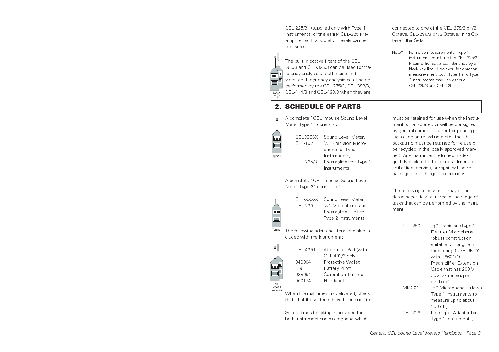
A complete CEL Impulse Sound Level
Meter Type 1 consists of:
CEL-XXX/X Sound Level Meter,
CEL-192
1
⁄2 Precision Micro-
phone for Type 1
Instruments,
CEL-225/3 Preamplifier for Type 1
Instruments.
A complete CEL Impulse Sound Level
Meter Type 2 consists of:
CEL-XXX/X Sound Level Meter,
CEL-230
1
⁄4 Microphone and
Preamplifier Unit for
Type 2 Instruments.
The following additional items are also in-
cluded with the instrument:
CEL-4391 Attenuator Pad (with
CEL-493/3 only),
040004 Protective Wallet,
LR6 Battery (4 off),
038054 Calibration Trimtool,
060174 Handbook.
When the instrument is delivered, check
that all of these items have been supplied.
Special transit packing is provided for
both instrument and microphone which
must be retained for use when the instru-
ment is transported or will be consigned
by general carriers. (Current or pending
legislation on recycling states that this
packaging must be retained for re-use or
be recycled in the locally approved man-
ner). Any instrument returned inade-
quately packed to the manufacturers for
calibration, service, or repair will be re-
packaged and charged accordingly.
The following accessories may be or-
dered separately to increase the range of
tasks that can be performed by the instru-
ment.
CEL-250
1
⁄2 Precision (Type 1)
Electret Microphone -
robust construction
suitable for long term
monitoring (USE ONLY
with C6601/10
Preamplifier Extension
Cable that has 200 V
polarization supply
disabled),
MK-301
1
⁄4 Microphone - allows
Type 1 instruments to
measure up to about
160 dB,
CEL-216 Line Input Adaptor for
Type 1 Instruments,
General CEL Sound Level Meters Handbook - Page 3
CEL-316 Line Input Adaptor for
Type 2 Instruments,
CEL-282 Acoustic Calibrator for
Type 2 Instruments,
CEL-284/2 Precision Acoustic
Calibrator for Type 1
and 2 Instruments,
CEL-278/3 Octave Filter Set (not
for CEL-266/3 or
CEL-328/3),
CEL-296/3 Octave/Third Octave
Autoscan Filter Set
(not for CEL-266/3 or
CEL-328/3),
CEL-2962 Windshield for
1
⁄2
Microphones,
CEL-4672/2 Windshield for
1
⁄4
Microphones,
CEL-4627 Tripod,
CEL-3025 Vibration Attachment,
CEL-3732/3 Mains Power Supply
(needs C4461/2 Cable),
CEL-338 Graphics Printer and Logger,
CEL-438 Noise Level Analyser,
CEL-433 Serial Interface,
C4493/10 Preamplifier Extension
Cable (10 m),
C6602/0.3 0.3 m Flat Ribbon Cable
Extension for C4493
Cable,
C4425/2 Signal Cable - Uher
4000 series analog
tape recorders,
C3526/2 Replay Cable - Uher
4000 series recorder to
BNC plug,
C4520 AC Output Cable - BNC
plug,
C4530A/1.5 Digital Output and
Control Cable for B, D
& CEL-493/3,
C6620/2 Output Cable for
CEL-493/3 - BNC plug
to Sony TCD D10 and
PRO II DAT Recorders
(needs CEL-6616
Adaptor),
SC174 Control Cable for
CEL-493/3 - 14-way
LEMO plug to specially
converted Sony TCD
D10 or PRO II DAT
Recorder Handset
(needs CEL-6616
Adaptor),
SC167 Signal and Control
Cable for CEL-493/3 -
14-way LEMO plug to
specially converted
Sony TCD D10 DAT
Recorder Handset,
SC161 Signal and Control
Cable for CEL-493/3 -
14-way LEMO plug to
specially converted
Sony TCD PRO II DAT
Recorder Handset.
These instruments are also available as
components of measurement kits.
Please contact your CEL representative
for details.
3. DESCRIPTION
3.1Technical Description
Type 1 Microphone
The standard Type 1
192 Precision Air Condenser Microphone
Page 4 - General CEL Sound Level Meters Handbook
1
⁄2 diameter CEL-
is available in free field (suffix F) versions
to meet IEC measurement standards and
random incidence (R) versions to meet
ANSI standards. The microphone capsule
is screwed on to a low noise CEL-225/3
Preamplifier which plugs into the tapered
end of the sound level meter.
The preamplifier supplies the 200 V polari-
zation voltage required by the micro-
phone, provides 30 dB or unity gain, and
conditions the output.
The CEL-225/3 Preamplifier can be identi-
fied by the black key line that should align
with a similar line on the sound level me-
ter. The CEL-225/3 Preamplifier is a devel-
opment of the CEL-225 used with earlier
sound level meters such as the CEL-275
and CEL-275/2 (which have no key line).
measurement requirements for both ran-
dom incidence (ANSI standards) and free
field (IEC standards).
For vibration measurement and analysis
with a Type 2 instrument, the CEL-230
Microphone/Preamplifier Unit must be re-
placed by a CEL-225/3 (or CEL-225) Pre-
amplifier which accommodates a
CEL-3025 Vibration Attachment screwed
on in place of a microphone to accept in-
put signals from an accelerometer.
The preamplifiers have a similar appear-
ance, but function in a different way, so
that although no damage would occur,
they should not be substituted for each
other when measuring sound levels.
When an earlier preamplifier is used with
a later sound level meter, the noise floor
for linear noise measurement will be
raised to about 70 dB. If an older series
of Type 1 sound level meter is used with
a CEL-225/3 Preamplifier for sound level
measurement, the instrument stabilisa-
tion time will be increased to at least
three minutes. Therefore, it is not recom-
mended to mix old and new versions.
When vibration measurement and analy-
sis is to be undertaken by a Type 1 instru-
ment, both types of preamplifier may be
used to accommodate a CEL-3025 Vibra-
tion Attachment. This is screwed on in
place of the microphone to accept input
signals from an accelerometer.
Type 2 Microphone
The standard Type 2
1
⁄4 diameter prepo-
larised electret microphone capsule is
permanently attached to a low noise am-
plifier to form a CEL-230 Microphone/Pre-
amplifier Unit that plugs into the tapered
end of the sound level meter. The charac-
teristics of the microphone satisfy the
Both types of microphone can be used re-
mote from the instrument when the pre-
amplifier is connected to the Sound Level
Meter via an extension cable. C4493/5
(5 m), C4493/10 (10 m), and C4493/20
(20 m) are standard cables, and a maxi-
mum length of 100 m can be delivered.
The C6602/0.3 (3 m) Flat Ribbon Cable
can be used to carry microphone signals
through door or window closures.
Input signals can be accepted from other
sources. For example when a CEL-216
Line Adaptor is used with a Type 1 instru-
ment or a CEL-316 Line Adaptor with a
Type 2 instrument, AC input signals with
a maximum level of 22.5V
in from a tape recorder, (and 21V
pk-pk
can be fed
AC
pk-pk
signals can be applied via the auxiliary
socket).
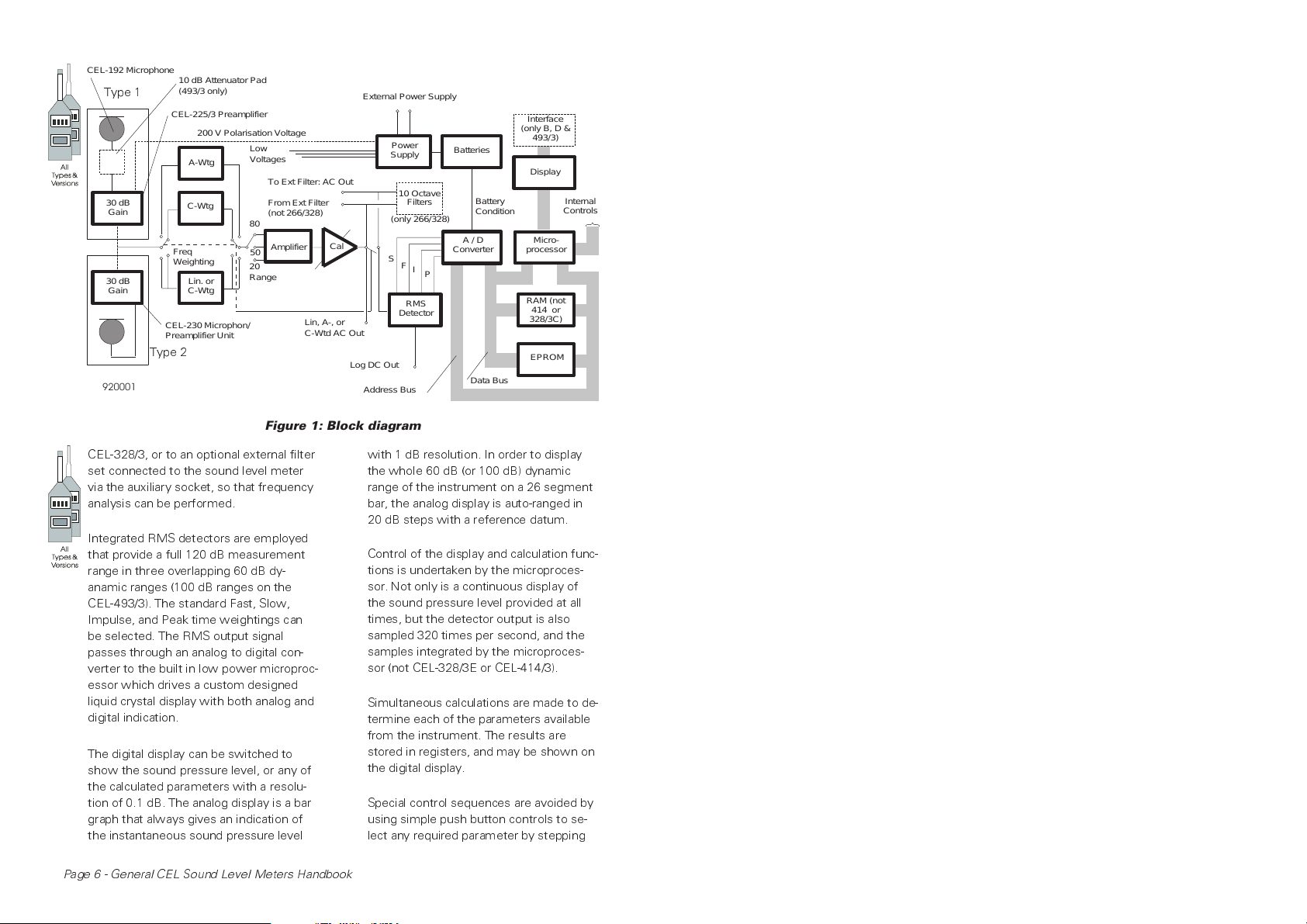
As can be seen from the block diagram in
Figure 1, the input from the preamplifier
can be switched to pass to the wide
range RMS detector through a variable
gain amplification stage with linear re-
sponse on A & B versions and the CEL-
493/3, and C-weighted on C, D & E
versions), or it may be passed through an
A-weighted filter that meets the require-
ments of IEC 651 Type 1. Linear, A- or C-
weighted signals are passed via a CAL
control, and may also be passed either to
the internal filter sets of a CEL-266/3 or a
General CEL Sound Level Meters Handbook - Page 5
CEL-192 Microphone
Type 1
30 dB
Gain
30 dB
Gain
Type 2
920001
10 dB AttenuatorPad
(493/3 only)
CEL-225/3 Preamplifier
200 VPolarisation Voltage
A-Wtg
C-Wtg
Freq
Weighting
Lin. or
C-Wtg
CEL-230 Microphon/
Preamplifier Unit
External Power Supply
Low
Voltages
To Ext Filter: AC Out
From Ext Filter
(not 266/328)
80
50
20
Range
Amplifier
Cal
Lin, A-,or
C-Wtd AC Out
Log DC Out
Address Bus
Figure 1: Block diagram
Power
Supply
10 Octave
Filters
(only 266/328)
S
F
I
P
RMS
Detector
Batteries
Battery
Condition
A / D
Converter
Data Bus
Interface
(only B, D &
493/3)
Display
Micro-
processor
RAM (not
414 or
328/3C)
EPROM
Internal
Controls
CEL-328/3, or to an optional external filter
set connected to the sound level meter
via the auxiliary socket, so that frequency
analysis can be performed.
Integrated RMS detectors are employed
that provide a full 120 dB measurement
range in three overlapping 60 dB dy-
anamic ranges (100 dB ranges on the
CEL-493/3). The standard Fast, Slow,
Impulse, and Peak time weightings can
be selected. The RMS output signal
passes through an analog to digital con-
verter to the built in low power microproc-
essor which drives a custom designed
liquid crystal display with both analog and
digital indication.
The digital display can be switched to
show the sound pressure level, or any of
the calculated parameters with a resolu-
tion of 0.1 dB. The analog display is a bar
graph that always gives an indication of
the instantaneous sound pressure level
Page 6 - General CEL Sound Level Meters Handbook
with 1 dB resolution. In order to display
the whole 60 dB (or 100 dB) dynamic
range of the instrument on a 26 segment
bar, the analog display is auto-ranged in
20 dB steps with a reference datum.
Control of the display and calculation func-
tions is undertaken by the microproces-
sor. Not only is a continuous display of
the sound pressure level provided at all
times, but the detector output is also
sampled 320 times per second, and the
samples integrated by the microproces-
sor (not CEL-328/3E or CEL-414/3).
Simultaneous calculations are made to de-
termine each of the parameters available
from the instrument. The results are
stored in registers, and may be shown on
the digital display.
Special control sequences are avoided by
using simple push button controls to se-
lect any required parameter by stepping

the digital display through the registers.
The following parameters may be se-
lected (and identified) on the digital dis-
play:
SPL Sound Pressure Level,
L
eq
Equivalent Continuous
Level (not CEL-414/3,
only octave band L
eq
on CEL-328/3E),
L
Tm3
Maximum A-weighted
Average taken over
3 second periods (A, B
& CEL-493/3),
L
Tm5
Maximum A-weighted
Average taken over
5 second periods (A, B
& CEL-493/3),
L
OSHA
Averaged level with
preset threshold and
q = 5 (C, D versions
but not CEL-414/3),
L
DOD
Averaged level with
preset threshold and
q = 4 (C, D versions
but not CEL-414/3),
L
max
Maximum Level
,
DUR Duration over which
measurements taken,
SEL Sound Exposure Level
(not CEL-266/3, CEL-
328/3 or CEL-414/3),
31-16k Octave bands centered
on indicated frequency
(only CEL-266/3 &
CEL-328/3).
Each parameter may be reset inde-
pendently from the other parameters,
while an internal clock with an accuracy
better than five seconds in 24 hours
measures the time elapsed from the start
of the measurement in hours and min-
utes.
The display will give an automatic indica-
tion of the following conditions:
¤
Signal overload,
¤
SEL Event in Progress (CEL-493/3
only),
¤
Use of linear or A-weighted signals
(A & B versions and CEL-493/3),
¤
Use of A- or C-weighted signals
(C&Dversions),
¤
Use of an external filter set (not
CEL-266/3 or CEL-328/3),
¤
Use of pause button (not CEL-414/3),
¤
Low battery.
Battery level can also be indicated by us-
ing the Battery position on the power
switch.
Both AC and DC analog output signals
proportional to the indicated value are
available from an auxiliary socket in the
base of the instrument. The conditioned
RMS AC output has a full scale deflection
value of 7.75 V, (8.0 V on the CEL-493/3)
while the DC output is a logarithmic sig-
nal nominally 48 mV/dB with a typical
maximum value not exceeding 5 V on all
instruments.
In addition to the analog outputs, the B
and D versions plus the CEL-493/3 are
equipped with a CEL low power digital in-
terface that allows them to feed all digital
data to a CEL-438 Noise Level Analyser,
CEL-338 Graphics Printer and Logger,
and CEL-238A Secondary Processor.
Alternatively, data on the selected pa-
rameter can be fed via a CEL-433 Serial
Interface to a suitably equipped com-
puter. This arrangement is very useful in
data logging applications, as two samples
per second of the SPL display are trans-
mitted in this way.
External control of digital functions is ex-
ercised via the interface, so that parame-
ter selection, and operation of pause and
reset functions can be performed re-
motely, or under program control.
General CEL Sound Level Meters Handbook - Page 7
Black
Key Line
Version
C, D & E
BAT
PSE
OSH
DOD
Version
A, B &
CEL-493/3
Pause Reset
CAL
Range
A
C
50
FA
FL
20
SEL__EVENT 1SM
BAT
PSE
LT3
L
LT5
40
+
DATUM 5 10 15 20 25
Function
P
I
F
S
ON80
BAT
OFF
LEQ
SPL
MAX
DUR
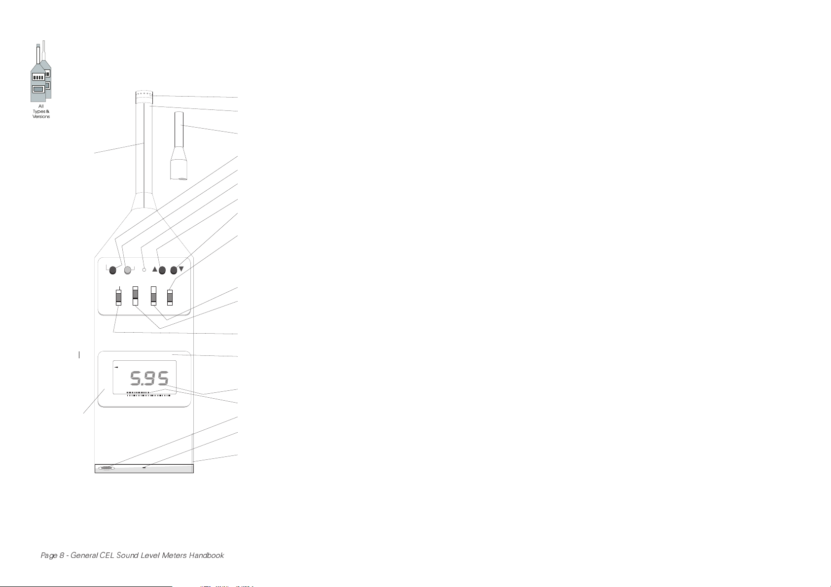
CEL- 192 Microphone (Type 1)
CEL-225/3 Preamplifier
(Type 1)
CEL-230 Microphone/
Preamplifier Unit (Type 2)
Pause (not CEL-414/3)
Parameter Reset
Calibration Potentiometer
Function Step (Counter-clockwise)
Function Step (Clockwise)
(not CEL-414/3)
On-Bat-Off (Power Switch)
Sets SEL Threshold Level &
Onset Time on CEL-493/3
Sets Threshold Level for
L L on C & D versions
OSHA DOD
P-I-F-S (Time Weighting Switch)
A-C-FA-FL (C, D & E versions)
A-L-FA-FL (A & B versions)
(Frequency Weighting Switch)
80-50-20 (Range Switch)
(Hi-Med-Lo on CEL-493/3)
SEL__EVENT 1SM
(Octave Centre Frequencies
on CEL-266/3 & CEL-328/3)
Digital Display
Analog Display
Auxiliary Socket
Filter Attachment Insert
(not CEL266/3 or CEL-328/3)
Battery Compartment
920002
Page 8 - General CEL Sound Level Meters Handbook
Figure 2: Front panel & instrument
controls
The interface uses four lines, two of
which are used for data transmission,
while the other two are for the hand-
shake request to send and clear to
send signals. Each digital output con-
sists of five bytes which describe the fre-
quency weighting, time weighting,
parameter selected, and its numeric
value. Use of the pause and reset func-
tions will also be indicated. More detailed
information on the output and input facili-
ties will be found in Sections 3.5 and 3.6.
3.2Control Facilities
The functions of the various controls are
identified by the legends marked along-
side them on the instrument front panel
as follows, (see Figure 2).
ON-BAT-OFF
This three position slide switch is the
main on/off control for the instrument. It
provides the following settings:
OFF No power is drawn from
the supply, nor any
function performed,
ON All instrument functions
are available as
described below,
BAT* The on-load battery
voltage is displayed,
while all normal
functions continue to
be performed.
Note*: On CEL-493/3, BAT position is also used
while setting the SEL event threshold
level and onset time.
Similarly, on C and D versions, the
BAT position is used while setting the
threshold for OSHA and DOD
measurements.
When the instrument is first switched
ON, the start up messages CEL to-
gether with the software issue number
appear on the digital display, changing af-
ter about five seconds to the instrument
type number (for example 275) with the
instrument version letter (A, b, C, d or E).
The analog bar graph steps along its seg-
ments to indicate that the microproces-
sor self checking procedures are being
operated. When this test has been com-
pleted satisfactorily, all measurement and
calculation functions become available.
Should the instrument fail the self test,
an error message will be displayed as de-
tailed in Chapter 12.
P-I-F-S (Time Weighting Switch)
A four position slide switch that selects
the time weighting required in the RMS
detector. It provides the following stand-
ardized settings:
P Peak: <100µs,
I Impulse: 35 ms rise time
and 1500 ms decay
time,
F Fast: 125 ms,
S Slow: 1 second.
A-L-FA-FL (Frequency Weighting &
Filter Switch - A & B versions and
CEL-493/3)
This four position slide switch provides
selection of the linear (flat) response or
the built-in A-weighting network, and the
use of external filter sets. The following
options are provided:
A Internal A-weighted
network,
L Linear response of
instrument (+0.5/-3 dB
typical points),
80 (Hi) Range 3.5 Hz
to 70 kHz,
General CEL Sound Level Meters Handbook - Page 9
50 (Med) & 20 (Lo)
Ranges 3.5 Hz to
40 kHz,
FA Either internal
A-weighted network
PLUS internal octave
filters, or external filter
set connected via the
auxiliary socket,
FL Either linear response
PLUS internal octave
filters, or external filter
set connected via the
auxiliary socket.
Note: On instruments that have no built in
octave filters, there will an incorrect
indication if FA or FL is selected when
no filter is connected.
A-C-FA-FL (Frequency Weighting &
Filter Switch - C, D & E versions)
This four position slide switch provides
selection of the built-in A- or C-weighting
network, and the use of external filter
sets. The following options are provided:
A Internal A-weighted
network,
C Internal C-weighted
network,
FA Either internal
A-weighted network
PLUS internal octave
filters, or external filter
set connected via the
auxiliary socket,
FL Either linear response
PLUS internal octave
filters, or external filter
set connected via the
auxiliary socket.
Note: On instruments that have no built in
octave filters, there will an incorrect
indication if FA or FL is selected when
no filter is connected.
80-50-20 (Range Switch: not
CEL-493/3)
This slide switch sets the gain of the am-
plifiers, and hence controls the measure-
ment range of the instrument. The three
dynamic ranges available are:
80 80-141 dB,
50 50-111 dB,
20 20-81 dB.
When 20 is set, the total dynamic range
is limited by the self noise of the pream-
plifier, approximately 20 dB(A), or
35 dB(Lin or C).
80-50-20 (Range Switch:
CEL-493/3 only)
This slide switch sets the gain of the am-
plifiers, and controls the measurement
range of the instrument. The three dy-
namic ranges available are:
Hi High (50-151 dB),
Med Medium (40-141 dB),
Lo Low (10-111 dB).
In Lo range, the total dynamic range is
limited by the self noise of the preampli-
fier, approx. 17 dB(A), or 35 dB(Lin).
FUNCTION
Two push buttons (one button only on
CEL-414/3) that are used to select a pa-
rameter for display.
The legends around the display bezel
shown in Figure 3 identify the different
parameters available. In turn, each pa-
rameter can be selected for display as
shown by an arrow marker on the screen
that points to the selected identity. This
is accomplished by using the push but-
tons (one for each direction) to step from
Page 10 - General CEL Sound Level Meters Handbook
one parameter to the next. Full details
are given in Table 1, page 2
during the pause so that the Operator
can see when the transient has passed.
Certain combinations of function and
time weighting must not be used, and
the instrument will not allow them to be
selected. For example, when the peak
time weighting is selected, ONLY the
maximum level can be selected.
PAUSE (not CEL-414/3)
This push button interrupts all calculation
procedures and allows unwanted tran-
sient signals to be excluded from the
measuring period.
The first press prevents all of the calcu-
lated values from being updated (includ-
ing the duration counter), holds the
currently indicated value on the digital dis-
play, and causes the pause condition to
be indicated. The second press unlatches
the pause condition and allows the calcu-
lations to proceed again from where they
were interrupted.
The analog bar graph continues to show
the instantaneous sound pressure level
A, B, and CEL-493/3
31 63 125 250 500 1k 2k 4k 8k 16k
RESET
This push button resets the parameter
currently indicated. For example, to reset
L
use the FUNCTION buttons to bring
max
the maximum value to the display, then
press RESET. The duration and all other
calculations continue without interruption.
3.3General Reset
A general reset of all parameters, includ-
ing duration, ensures that all registers are
synchronised. It is applied only when the
setting of one of the following controls is
changed.
80-50-20 Range Switch,
A-L-FA-FL or
A-C-FA-FL Frequency Weighting &
Filter Switch,
P-I-F-S Time Weighting Switch.
Note: The push button RESET operates only
on the parameter being displayed at
the time the button is pressed.
Only CEL-266/3
and CEL-328/3
C, D & E Versions
BAT
PSE
BAT
OSH
PSE
DOD
1SM
CEL-414/3
920003
BAT
PSE
LT3
LT5
SEL EVENT
F
A
L
C
LOW BAT OVERLOAD
40
+
DATUM
10 15 20 255
1SM
LEQ
SPL
MAX
DUR
SPL
MAX
DUR
CEL-414/3
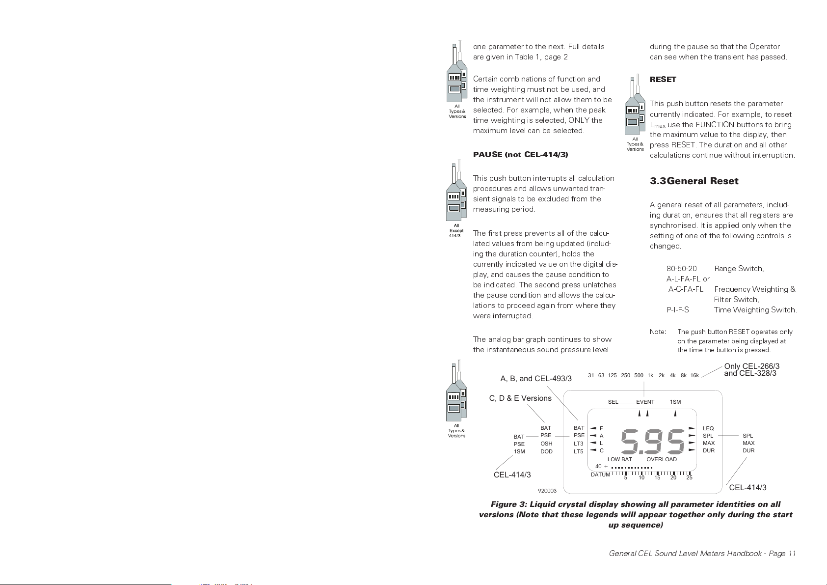
Figure 3: Liquid crystal display showing all parameter identities on all
versions (Note that these legends will appear together only during the start
up sequence)
General CEL Sound Level Meters Handbook - Page 11
3.4Display
Function Indicators
Figure 3 shows the display with the vari-
ous parameters that may be indicated as
follows.
Bar Graph & Datum Indicator
This gives an analog indication of the
instantaneous sound pressure level as
soon as the self test sequence has been
completed. It continues to show the
sound level for as long as the instrument
is switched ON and has sufficient battery
power.
The indicated level is consistent with the
settings of the range, frequency weight-
ing, and time weighting switches.
The graph has 26 segments which indi-
cate the level in 1 dB steps above the da-
tum indicated to the left of the bar. When
the level approaches either full scale or
minimum deflection, it is auto-ranged in
20 dB steps, and the new datum dis-
played. This arrangement allows the bar
graph to cover the three full 60 dB dy-
namic ranges of the instrument (CEL-
493/3 has 100 dB dynamic range).
Main Display
This four digit display is the instruments
primary indicator. It displays the parame-
ters measured in dB as hundreds, tens,
units, and decimals, and time information
as hours and minutes separated by a co-
lon (:).
When the instrument is first switched on,
the alphanumeric legends CEL and
software issue number followed by the
instrument type number and version let-
ter are displayed for approximately 10 s
while the start up sequence is in opera-
tion.
These are letters that indicate which filter
or weighting network is in use, and a se-
ries of arrows that point towards the leg-
ends on the bezel. The filter and
weighting network indication letters are
as follows.
A A-weighted network,
L Linear response (A, B
& CEL-493/3),
C C-weighted network
(C, D & E versions),
A, F A-weighted network
PLUS internal or
external filter set,
L, F Linear response PLUS
internal or external
filter set.
The arrows indicate which parameter is
being displayed, normally with only one
arrow at a time active as follows.
L
eq
Equivalent Continuous
Level (not CEL-414/3
and only octave band
L
with 328/3C),
eq
SPL Sound Pressure Level,
L
max
Maximum Level,
DUR Duration over which
measurements taken,
L
Tm3
Maximum A-weighted
Average taken over
3 second periods (A, B
& CEL-493/3),
L
Tm5
Maximum A-weighted
Average taken over
5 second periods (A, B
& CEL-493/3),
L
OSHA
Averaged level with a
preset threshold and
q=5(C&Dversions
but not CEL-414/3),
L
DOD
Averaged level with a
preset threshold and
Page 12 - General CEL Sound Level Meters Handbook
q=4(C&Dversions
but not CEL-414/3),
SEL Sound Exposure Level
(not CEL-266/3
CEL-328/3 or
CEL-414/3),
31-16k Octave bands centered
on indicated frequency.
Certain specialised applications require
that the one second maximum (1SM)
specified in IEC 651 para 7.8 be adopted
for the SPL function. This operating
mode may be invoked by adding a link as
described in Section 10.2. When the link
is included, an automatic indication is
given against the 1SM legend instead of
SPL, which will not be available.
Overload
The OVERLOAD legend appears be-
low the main digital value if any of the
overload detectors in pre- and post-
weighting, or in the RMS detector are ac-
tivated.
When SPL mode is selected, an overload
indication is given only during the actual
overload period. However, as the dwell
time is approximately two seconds the
operator can detect even brief overloads.
In memory modes, the overload indica-
tion is a latching function that can be re-
leased by performing a general reset of
the instrument as described in Section
3.3, or by resetting the relevant parame-
ter individually by pressing the RESET but-
ton.
Low Battery
When the battery voltage falls below ap-
proximately 3.2 V, the LOW BATT mes-
sage is displayed. This can be reset only
by switching the instrument off, replacing
the batteries, and restarting the measure-
ment sequence.
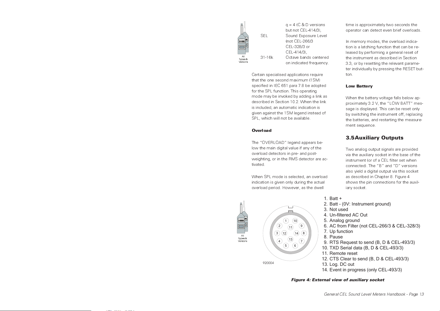
3.5Auxiliary Outputs
Two analog output signals are provided
via the auxiliary socket in the base of the
instrument (or of a CEL filter set when
connected). The B and D versions
also yield a digital output via this socket
as described in Chapter 8. Figure 4
shows the pin connections for the auxil-
iary socket.
920004
Batt +
1.
Batt - (0V: Instrument ground)
2.
Not used
3.
Un-filtered AC Out
4.
1
10
2
3
4
121314
56
9
11
8
7
Figure 4: External view of auxiliary socket
Analog ground
5.
AC from Filter (not CEL-266/3 & CEL-328/3)
6.
Up function
7.
Pause
8.
RTS Request to send (B, D & CEL-493/3)
9.
TXD Serial data (B, D & CEL-493/3)
10.
Remote reset
11.
CTS Clear to send (B, D & CEL-493/3)
12.
Log. DC out
13.
Event in progress (only CEL-493/3)
14.
General CEL Sound Level Meters Handbook - Page 13
 Loading...