


CEL-393
Precision Computing
Sound Level Meter &
Frequency Analyser
Operator's Handbook
for
archive Document
Discontinued Instrument
060023
Issue: 6A
April 1994


Contents Page
1. INTRODUCTION ..................1
2 SCHEDULE OF PARTS ..............5
3. PREPARATION FOR USE ............11
4. DESCRIPTION OF THE INSTRUMENT .....15
4.1 Controls, Connectors and Display ....15
4.2 Display ..................26
4.3 Interpretation of Results .........29
4.4 Auxiliary Outputs .............35
4.5 Auxiliary Input ..............37
4.6 Alternative Microphones & Preamplifiers 38
5 VERSION B - ADDITIONAL FUNCTIONS ....39
5.1 Introduction ...............39
5.2 Frequency Analyser ...........39
5.2.1 Controls .................40
5.2.2 Operation ................42
5.3 Digital Interface .............47
5.3.1 Introduction ...............47
5.3.2 Operation with IBM Compatible Personal
Computers ................48
5.3.3 Operation with Epson HX-20 Portable
Microcomputer ..............50
5.3.4 Digital Interface -General Description . . 54
5.4 Memory Configuration ..........58
5.5 Retrofitting Procedure ..........58
393 Handbook
i

Contents (Continued) Page
6 SAMPLE OPERATIONS .............61
6.1 Profile Mode ...............61
6.2 Environmental Mode ...........63
6.3 Event Mode ................66
6.4 Frequency Analysis Mode ........68
7 DEFAULT CONDITIONS .............73
8 CALIBRATION PROCEDURE ..........63
8.1 Introduction ................75
8.2 CEL-284/2 Electro Acoustic Calibrator . . 78
8.3 Pistonphone Calibration .........79
9 BATTERY & AUXILIARY POWER SUPPLIES . . 83
10 SPECIFICATION .................85
11 MANUFACTURERS SERVICING & WARRANTY
ARRANGEMENTS ................91
11 CALIBRATION CERTIFICATE ..........95
ii
393 Handbook

1. INTRODUCTION
Thank you forchoosing the CEL-393 Precision Computing Sound Level
Meter.
CEL experience in both Acoustics and Data Processing combine to
produce a full specification computing sound level meter to assist engineersinthecontrolof excessive noise and vibration.Thelatestadvances
in micro-electronics have been employed to reduce the size of the
instrument considerably, whilst the on-board microprocessor simplifies
its operation and extends the facilities provided.
The CEL-393 represents the new concept of a sound and vibration
analysis laboratory in a slim line 'pocket-sized' package that is equally
at home in the evaluation of environmental noise nuisance or the
assessment of noise deafness risk in industry. Within the compact
dimensions of the CEL-393 are to be found a wide range of functions
that were previously available only with bulky laboratory systems.
The instrument has a 63dB dynamic range with an on-board computer
controlling the custom designed display to provide both conventional
analogue and fully annotated digital results. It will compute and store a
wide range of noise rating descriptors including four L
three L
DC outputs are provided to feed ancillary instruments such as tape and
graphic level recorders.
values plus the maximum value. Both conditioned AC and Log
n
based units,
eq
Fittingtheoptionalfilter module allows both octave and third octave band
analysis to be undertaken, either manually, or with a high level of
automatic control. This is achieved either by passing command to the
internal microprocessor or by an external device such as the CEL-160
Graphic Recorder. The filter option also provides a general purpose
digital output suitable for use with the CEL-238, -338, -438 family of
DigitalProcessor/Printers, or to a wide range ofconventionalcomputers.
In normal operation the instrument is in the current mode, and will
indicate the current SPL levelon both its analoguebar graph display and
393 Handbook /1.

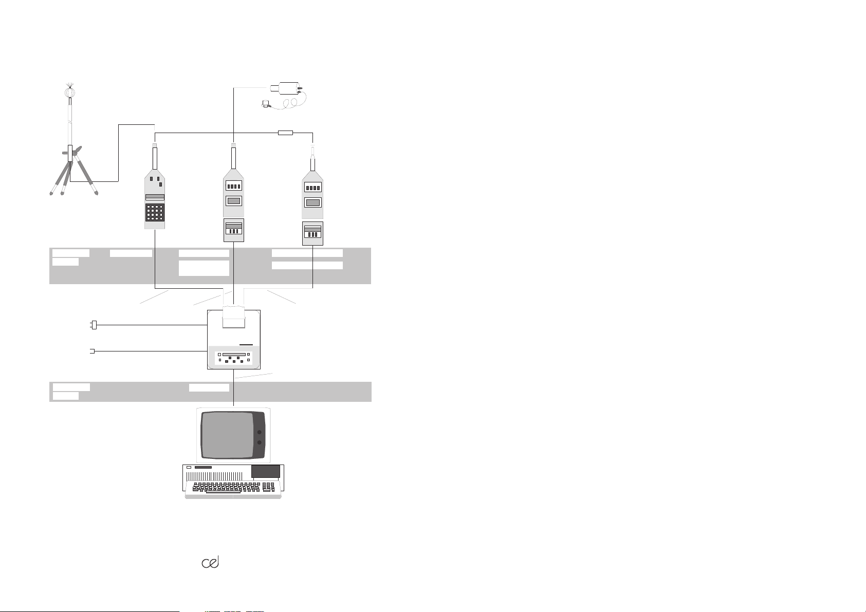
Optional
CEL-2942A/5
Cable
890009
Optional
CEL-2962
Windshield
CEL-186
Microphone
CEL-299
Preamplifier
Optional
CEL-3025
Vibration Kit
A-Wgt
Operator
Control
Matrix
Overload
Control
Logic
Conditioned AC Output
Oct/
1
/3Oct
Filter
RAM
Display
Driver
Range
Control
System
Pro-
cessor
Internal Data Bus
Display
ROM
Operator
Control
Matrix
FP IS
RMS
Log DC Output
Interface
Recorder
Interface
Digital
Level
DA
CEL-238
Sec'dary
Pr'ssor
CEL-160
Level
Recorder
Power
Supply
Intl/Extl
Figure 1 Block diagram of CEL-393B
on the main digital display. In addition, the computer is continually
sampling this level every 15ms, and the data is used to calculate the
noise rating parameters.
These parameters are the L
The statistical L
parameters calculated are normally L10,L50and L90,
n
eq,LTm3,LTm5,Lmax
and three Lnvalues.
however, alternative values are available on option. They are described
in Chapter 2 of this handbook.
The computed results are available throughout the current period along
with the SPL, and are continually updated and therefore always correct.
A comprehensive memory facility for these results is also provided and
this operates in four distinct modes. The memory modes provided are:
/2.
393 Handbook

i) Profile Mode
This allows the operator to set a period time. The instrument will then
calculate and store the L
result for each individual period, then reset
eq
the current period answer and commence a new current period measurement.
ii) Environmental Mode
Hereagain the required periodduration is keyed into theinstrument, and
attheendof each period,theCEL-393willretain thecomputedL
L
Tm5,Lmax
L
10,L50
, and three Lnvalues, which depending on software may be
andL90. It will thenresetthecurrent period answer registers and
eq,LTm3
commence a new calculation.
iii) Event Mode
In this configuration the instrument will detect all significant noise events
by means of the exceedance of a pre-selectable threshold level. Each
event will be retained in the memory in terms of its time of occurence,
duration, maximum level and its calculated SEL (L
AX
).
iv) Frequency Analysis Mode
This memory configuration is only availablewhen the frequency analysis
module has been fitted. When an automatic frequency sweep is made,
the level in each filtered band is stored along with the band centre
frequency and sweep start time. The results may therefore, be recalled
to the display at the end of the analysis.
,
All stored results are retained as long as the instrument remains powered, and may be recalled to the display by operator keystrokes as and
when required. Results may be readout at any time without affecting the
operation of the instrument. In order to maximise the availabile memory
space, a delayed start facility is provided that will allow only the required
answers to be held in store.
393 Handbook /3.
CEL-186
MICROPHONE
CEL-298/2
PREAMPLIFIER
CEL-3025
VIBRATION
ATTACHMENT
CEL-225 or 225/3
CEL-194/2X OUTDOOR
MICROPHONE
CEL-4627 TRIPOD
CARDS
C4529/2
C6335/2 12V POWER CABLE
PROGRAM
CARDS
CEL-186
CEL-393AX & B
C4530A/1.5
C4526/2 MAINS CABLE
IBM PC
OR SIMILAR
CEL-4853/2 CEL-4854/2 3B typesCEL-4566/2PROGRAM
CEL-5739/2
(EVENT CARD)
CEL-4856/2
CEL-192
CEL-225/3
CEL-493/3
CEL-278/3
CEL-296/3
CEL-288
CEL-438
CEL-338
CEL-238
RS232C LINK
C4850/1
CEL-230
CEL-275/3B
CEL-275/3D
CEL-383/3B
CEL-383/3D
CEL-278/3
CEL-296/3
CEL-288
CEL-6026/2 3D types
C4530A/1.5
920030
A Selection of Accessories for the CEL-393 Sound Level Meter
/4.
393 Handbook

2 SCHEDULE OF PARTS
TheCEL-393isavailable without orwithitsfrequencyanalysis and digital
interfacemodule,andidentifiedastheAandB models respectively. Both
of these versions are equipped with the CEL-186 series microphone.
Two other versions for the measurement of very low sound levels are
also available. These employ the CEL-190 high sensitivity microphone
which lowers the measured levels by 10dB. When this microphone is
supplied the units aredesignated CEL-393C (without filterand interface)
and CEL-393D (with filter and interface) respectively.
Throughout this manual, reference to CEL-393 indicates that comments
apply to both the A and B versions, while references to CEL-393B, for
example, apply only to that version of the instrument. Similarly, descriptions of the A version also apply to the C version and of the B to the D
unless stated to the contrary.
Instruments that have the filter board fitted as original equipment have a
B or a D added to the end of theserial number. The presence ofthe filter
in an instrument is best detected by selecting either the octave or third
octave filter positions on the filter switch (Figure 4). If the module is not
present the bar graph will not operate, and the mnemonics forfrequency
bands will not appear.
Instruments are provided with the three L
and L90. However, a number of variants are available as optional
L
50
values normally set to L10,
n
initial equipment or as retrofit programs: they are listed in Table 1.
The program installed in each individual instrument is noted both on the
calibration certificate contained in Chapter 12 as the ROM part number,
and on a label fitted to the rear of the instrument adjacent to the battery
cover (Figure 2). The last two digits of this code are the software issue
number, and hence they will be revised upwards as improvements are
included. In the absence of any of this information the software variant
may always be deduced from the L
mnemonics that appear on the
n
display.
393 Handbook /5.

Table 1 Software variants for the CEL-393 series
Model Number
CEL-393A
CEL-393B
CEL-393C
CEL-393D
Software Variant
0
1
2
3
4
8
0
1
2
3
4
8
0
1
2
3
4
0
1
2
3
4
LnValues Provided
10, 50, 90
1, 50, 95
1, 10, 50
1, 5, 95
5, 50, 95
1, 10, 90
10, 50, 90
1, 50, 95
1, 10, 50
1, 5, 95
5, 50, 95
1, 10, 90
10, 50, 90
1, 50, 95
1, 10, 50
1, 5, 95
5, 50, 95
10, 50, 90
1, 50, 95
1, 10, 50
1, 5, 95
5, 50, 95
It is possible to provide any of the listed L
options by ordering new
n
programme ROMs which may be installed in the instrument by following
the procedure outlined in Section 5.5.
Acomplete "CEL-393 Precision Computing Sound Level Meter" contains
thefollowing items. When the instrumentisdelivered,check that all items
on this schedule have been supplied.
/6.
393 Handbook

CEL-393 Precision Computing Sound Level Meter
(A, B, C, or D version),
CEL-229 Microphone Preamplifier,
CEL-186 Precision Measurement Microphone
(or alternative) for A or B versions,
CEL-190 Precision Measurement Microphone
(or alternative) for C and D versions,
040007 Protective Wallet,
016014 Battery, Alkaline Manganese Type
(IEC Type 6LF22),
060023 Handbook,
Miscellaneous accessories including screwdriver, calibration
trim tool, and transit packing.
Specialised transit packing is provided with each instrument, and although the protective wallet is suitable to ensure unnecessary deterioration in general use, the packing should be retained for use when the
instrument is transported or consigned by general carriers. It should be
noted that any instrument returned for calibration verification or other
attention that is inadequately packed will be returned with the correct
transit packing and charged accordingly.
The instrument is also provided as part of a complete measurement kit
underseparatereferencenumbers.Detailsofthesekitsmaybeobtained
from CEL Instruments sales agents. As an alternative to obtaining a
complete kit, the various accessories may be specified separately. The
following items are among the most popular, helping to gain the maximum benefit from the instrument:
CEL-3025 Vibration Measurement Kit
Allows the instrument to measure and analyse vibration levels in terms
of vibrational acceleration, velocity and displacement. Results are provided as levels in dB or in imperial or metric engineering units.
393 Handbook /7.

CEL-284/2 Acoustic Calibrator
Acoustic calibrator conforming to IEC-942 Class 1.
Note: For C and D versions, and certain official verifications use RFT 05001.
Full details in Chapter 8 of this manual.
CEL-2962 Windshield
Reduces wind induced noise and protects the microphone. See Section
4.6 of this manual for information on long-term outdoor operation of
microphone and preamplifier.
C2942A/5 Cable
Extension cable to allow remote installation of microphone and preamplifier. Normally 5m but 10m and 20m versions are available under part
numbers C2942A/10 and C2942A/20 respectively.
CEL-160 Graphic Recorder
Provides level against time charts, and level against frequency for the B
version. Includes transient recorder, expanded trace and reverberation
time options. Cable set C4209/2 required.
CEL-238, CEL-338, CEL-438 Digital Processor/Printers
Provide alpha-numeric and graphical print out of computed answers.
Additional processing and memoryfacilities are alsoavailable. Connecting cables and programme cards must be specified separately. Cable
type C4529/2 required.
CEL-3732/2 Power Supply
Mains power supply for all versions of CEL-393. Specify whether for
200/240 V ACor 100/120 V AC operation. Cable type C4210/2 required.
/8.
393 Handbook

CEL-433 Interface
Allows B (and D) version to be connected to conventional RS-232C
interfaces. Cables must be specified separately. See Section 5.3 of this
manual.
CEL-4627 Tripod
Will support either just microphone and preamplifier assembly or the
complete instrument. Supplied complete with carrying bag.
New accessories andoperational configurations are beingdeveloped all
the time hence it is important to return the user registration card in order
to receive software and application information updates.
393 Handbook /9.

/10.
393 Handbook

3. PREPARATION FOR USE
The CEL-393 is despatched from our works fully calibrated and tested,
hence it is only necessary to fit the battery and connect the microphone
and preamplifier in order to prepare it for service.
Before installing the battery, ensure that the weighting switch (Figure 3)
isinthePOWEROFFposition.Thebatteryislocatedinthecompartment
accessible through the cover situated in the bottom right hand corner of
the back plate of the instrument. Removing the single retaining screw
gives access, and the battery may then be located as shown in Figure
2.
Prior to pressing the battery into place, it is necessary to locate the pull
up ribbon between the contact studs to facilitate battery removal, ensuring that it does not interfere with the contact arrangement.The battery
should be inserted angled base first, and then pushed home so that the
batterycontacts locate against thespring contacts which also securethe
battery in place.
Special care must be taken to ensure that the battery is connected with
thecorrect polarity. The +veterminal stud on thebattery goes to the right
as the instrument is viewed from the rear. Once the battery is correctly
connected, the cover may be replaced to secure the cell in place.
Correct battery installation may be verified by switching the unit ON,
whichwillbringthe mnemonictothedisplayalongwiththebattery
voltage for about 25 seconds. Battery voltage should be greater than
6.5V for correct operation of the A version, and greater than 6.8V for the
B version.
Itisimportantthat only therecommendedalkalinebatterytypes are used.
Zinc-carbon batteries are not suitable for use in these instruments.
Reference should be made to Chapter 9 of this Handbook for further
information relating to both internal and external power supplies.
393 Handbook /11.

Warning
Ensure that the instrument is switched OFF whenever connections or disconnections are made.
The preamplifier may be fitted directly into its socket on the top of the
instrument by offering it up, rotating until it locates in the keyway and
then pushing it home. Having connected the preamplifier, it is a simple
mattertoscrew themicrophoneontothetop (Figure4).Itis notnecessary
to secure the microphone more than 'finger tight' as excessive force on
thecapsule could distort the diaphragmandtherebyaffectits calibration.
It is recommended that the instrument is always used inconjunction with
the CEL-2962 Windshield which is simply pushed over the microphone
and preamplifier assembly. The instrument itself may be hand held at
arms length, or for long measurements, it may be mounted on the
CEL-4627 Tripod by means of the bush located in the rear cover.
Alternatively, the microphone and preamplifier may be mounted in a
remote location, using the adaptor provided with the tripod, and connected to the instrument via the 5 metre extension cable type C2942A/5
(10 metre and 20 metre cables are also available under the same part
number with the suffix changed to 10 or 20 respectively).
/12.
+ve
Ribbon
-ve
Battery
890014
Figure 2 Battery insertion
393 Handbook

The instrument is not designed for permanent outdoor operation, however the optional CEL-298/2 Preamplifier and its associated CEL-194/2
Outdoor Enclosure may be connected to the CEL-393 for this type of
measurement. Further details are included in Section 4.6.
CEL-393 is now ready for service, and in line with accepted good
practice, it is recommended that the instrument's calibration be verified
by a competent laboratory annually, and that it is checked at the
beginning and end of each major measurement sequence. The procedure for this is outlined in Chapter 8.
Having connected the microphone and preamplifier and inserted the
battery the instrument may be switched ON. It will default to the battery
check condition for approximately 20 seconds during which time it will
display the on load battery voltage. End of battery life is at 6.5V. (6.8v
on B version) and the battery must be replaced if it shows a lower value.
393 Handbook /13.

/14.
393 Handbook

4. DESCRIPTION OF THE INSTRUMENT
4.1 Controls, Connectors and Display
Figure 3 shows the location of the various controls, connectors, and the
display, whilst set out below are the functions of the various switches.
Thischaptercanbe taken asashortforminstructionset, andshouldallow
those familiar with advanced acoustic instruments to operate the instrument successfully. For those who are less familiar, Chapter 6 contains
sample operations in the four operating modes.
FILTERS Switches
Lin - A - POWER OFF
When this switch isin the POWER OFFposition, no power isdrawnfrom
the batteries nor are any functions performed. The instrument operates
with the switch set to either of the other positions, A or Linear (Flat)
frequencycharacteristic,withtheselectedfrequencyweightingindicated
on the display (see Figure 4).
Frequency weightings are in series with the filter functions, allowing
A-weighted spectra to be produced if required. It should also be realised
that the current period answer calculation, and any results stored in the
memory are reset when this switch is moved between the A and Lin
positions.
At switch on, the instrument will indicate the battery voltage for approximately 20 seconds, andthen revert to its default set ofconditions. These
default conditions are described in Chapter 6.
Off - 1:1 - 1:3
This switch functions only on B and D versions of the instrument, and
must be left in the Off position on A and C versions.
393 Handbook /15.
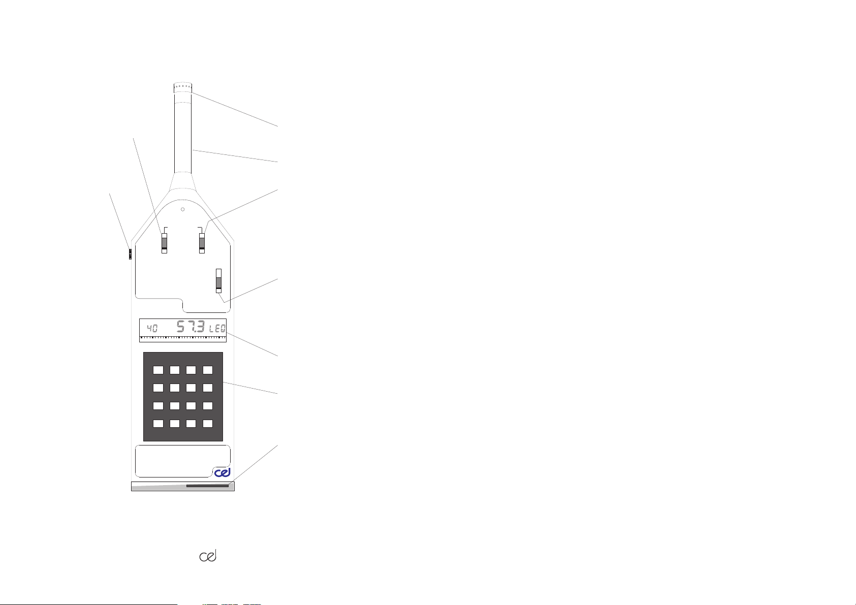
Frequency analyser
(B version only)
CEL-186 Microphone
CEL-229 Preamplifier
Conditioned AC
Output
CAL
FILTERS
Off
F1:1
F1:3
POWER
123
456
789
0ACP
Lin
A
OFF
DETECTOR
R
F
M
Power, frequency weighting
& general reset
F
P
I
S
Time weighting
Main display
Keypad
Auxiliary
Socket
/16.
890015
Figure 3 Controls & connectors
393 Handbook

When the switch is in the Off position, signals are treated as selected on
theweightingswitchdescribed above. In theotherpositionseitheroctave
or third octaveanalysis functions are selected and these modes arefully
described in Chapter 5.
Detector F - P - I - S
This switch sets the time constant used within the RMS detector. The
settings provide the internationally standardised responses:
F Fast (125 milliseconds),
P Peak (100 microseconds),
I Impulse (35 milliseconds risetime, 1.5 seconds
decay,
S Slow (1 second).
The setting to be used in any given measurement situation is usually
specified in the measurement protocol being followed. In the absence of
any specific statements, use the F setting.
Alltimeconstantsmaybe used inconjunctionwithanyofthe instrument's
functions, and their effect is overiding.
It should be noted that the 100 microsecond time constant for the peak
setting is faster than the display refresh rate and sample speed. Therefore, the peak setting is best used in conjunction with the maximum
capture arrangement. Again, as with the weighting switch, a reset is
applied when the control isoperated, to avoid confusionwiththe settings
used on answers stored in the memory.
Keypad.
Other controls are exercised via the keypad, which comprise both
numerical and control keys.
Until experience has been gained in using the instrument it is advised
that selections should be made from the SPL mode ie, after switch on,
wait until the battery check has been completed and the instrument will
393 Handbook /17.

always default to SPL. In order to return to the SPL mode after any of
the computed functions have been displayed, depress the F key.
Ingeneral,thekeypadrequiresoperationofone numerical key followed
by one of the control keys. It is important to note that the instrument
registers the numeric keystrokes and then waits for a control key.
Therefore, if an incorrect selection is made, the sequence must be
completed with the operation of the control key, and then the correct
sequencere-entered.Thecontrol key must be operatedwithin4seconds
of the number key otherwise the numeric instruction will be lost.
The control keys are denoted by letters and provide the following
functions:
R Range (& period reset),
M Memory,
F Function,
P Pause (kHz multiplier in filter mode),
C Clock (& cumulative reset),
A Analyser.
Range.
The measurement range is selected by pressing the number key that
corresponds to the tensdigit of therequired range, followed byR.Hence
5R will select 50dB range (measurement span 50-113dB).
Rangesfrom10dBthroughto90dBmaybeselectedonAandBversions
(10 - 80dB on C and D versions), and will initially be indicated by the
minimum scale deflection datum indicator on the bar graph shown in
Figure 4.
However, because the autoranging feature is included in the bar graph
display, it may not always be clear to which range the instrument is set,
as the minimum scale deflection indicator will range upwards as the bar
graph approaches full scale deflection. A single operation of the R key,
without a preceding numeral, will force the minimum scale indicator to
therangedatum level. The current measurementspanisthen calculated
/18.
393 Handbook

fromthisdisplayeddatumplus63dB; ieon30range,answersinthespan
30.1to93arevalid.This procedure will not affect the main digital display.
It should be noted that the instrument goes into the pause mode for
approximately 10 seconds upon range changing (35 seconds between
70 and 80dB ranges on A and B versions, 60 and 70dB on C and D
versions), to allow circuit constants to normalize. It should also be
remembered that the sound level is sampled and the various rating
parameters are computed from this data all the time the instrument is
switched on. These are known as the current period results, and they
may be reset by the key sequence 0R. This cancels the accumulated
data to date and starts a new current period.
Function
TheFkeyselectsthecurrent periodanswerfordisplayonthe main digital
display. When operated without a preceeding numeral, it will bring the
current SPL value to the main digital display, which will then duplicate
the bar graph level.
The various functions calculated from current period data are selected
for display by a number code followed by the F button. These functions
are called to the display by the sequences shown in Table 2.
Table 2 Keypad sequences for current period results
Key Sequence
0F
1F
2F
3F
4F
5F
6F
7F
Answer
Maximum
L
eq
L
Tm3
L
Tm5
L
10
L
50
L
90
SEL
Mnemonic
CommentsDisplayed
Update once per 3 or 5
second period
Or alternative values
provided by options
Only valid in event mode
393 Handbook /19.

Function 9F is described in Chapter 9, whilst 8F duplicates the single
operation of the C key. The sequence 7F is only valid when the instrument is in the event mode.
Clock
This key is used for all time functions. Operation of the key alone results
in the display of time functions in sequence, whilst preceeding it with a
number will enter new time information. The procedure for reading the
time information is therefore asequenceofoperations of the C keyalone
as follows.
1st operation of C key displays the main clock (real or elapsed
time),
2nd operation of C key displays selected period time,
3rd operation of C key displays time left in current period,
4th operation of C key displays selected delayed start time.
SubsequentoperationoftheCkeywillreturntothemainclock,andallow
the sequence to be run through again.
The default time settings at switch on are.
0 hours 00 minutes for the main clock, to allow a display of
elapsed time from switch on,
9999 minute period time, giving event mode of data storage
with no defined state for the elapsed time display but with the
delay time flag set off to allow the microprocessor access to
the memory for its computed results.
In order to set any of the time functions to other values the following
procedure should be followed.
/20.
393 Handbook

Main Clock
To change the defaultelapsed time mode to thecurrent real time itis just
necessary to enter the required time in hours and minutes on a 24 hour
clock basis. This time will be entered when the C key is pressed.
The programme will identify the sequence of four numerical keys followed by C as a request to reset the main clock. Always hours before
minutes, and always four digits are necessary for the correct entry
procedure.Theclockis arranged ona24hourcumulativebasis, enabling
the number ofdays elapsed to be indicated (i.e. time between24.00 and
48.00 represents time on second day).
Period Time
The required period time should be entered in minutes within the range
1 to 999 (1min to 16 hours 39 mins), followed by C. The program will
identifyasequenceof 1, 2,or3numericalkeys followedbyCasa request
to reset the period time.
Notethatselectionof5, 10, 30or60minuteperiods will cause theperiods
to synchronise with the main clock. When a 60 minute period is selected
for example, this will result in an answer set being stored on each hour,
with the first period being shortened to obtain synchronisation. All other
times are asynchronous, taken from the moment of period time entry.
To select an infinite period time, taken as 9999 minutes (166 hours 39
minutes), follow the key sequence 0 then C. This sequence is used in
event and frequency analysis modes to inhibit period data from being
written into thememory. Current periodresults may still be read from the
display, but it should be noted that there is a limit to the maximum
duration of any current period calculation due to the size of the current
data store register.
Details of these limits are found in Section 4.3, for each individual
parameter, whilst the time over which any current period result hasbeen
accumulated may bedetermined by comparing the decrementing period
timer with the set period time.
393 Handbook /21.

Delayed Start Time
Thisisenteredas a four digit number representing therequiredstarttime
on a 24 hour clock, in the same 24 hour cumulative manner as the main
clock, allowing delays over into following days to be programmed. It is
enteredby the key sequence 0followedby C. Therefore, the programme
identifies five numerals followed by C as a request to preset the delay
start time. However, only the first four digits, are read by the programme
as data.
When a delay start time has been entered, the delay start flag is set on,
while the measurement sequence continues as normal. However, the
period counter will not decrement, and hence no answers can be stored
until after the delay start time has passed. When the main clock passes
the delay time, the delay flag is set off, and the period clock will start
decrementing.
It is important to appreciate that the delay start time operates in the
environmental mode only. Resetting current period data (0R), changing
period time, or resetting the main clock cancels the delay start request,
but leaves the time set in the display register. Hence to use the delay
start time function, it must be the last operating condition loaded.
Alternatively the 'del' time may be used to indicate the start time of a
measurementsequence by setting itto the start time priorto entering the
period time. This provides a convenient reference to the start time when
the results are reviewed.
Memory
The memory mode is related to the selected period time, and resetting
the main clock or the period time will reset all stored data and cancel the
delay start flag.
The memory key (M) is used to index the contents of the memory, and
it is important to appreciate which memory mode is in use, in order to
understand the operation.
/22.
393 Handbook

The various memory modes are as described above in Chapter 1, and
it is important to note that three of the modes are linked to the selected
period time as set out below, whilst the fourth mode is available only
when the frequency analyser is being used.
i. Profile Mode for period times 1 - 4 minutes,
ii. Environmental Mode for period times from 5 - 999 minutes,
iii. Event Mode for a period time of 9999 minutes. (0C),
iv. Frequency Analysis Mode (only in conjunction with analyser).
The procedure for setting the period times has been dealt with in the
section dealing with the clock. The selected period time may be read on
the display by operating the C key twice, and the memory mode determined from this display.
At the end of each of the selected measurement periods, answers will
be calculated and stored in the memory in both the Profile and Environmental modes. In the Event mode, answers are stored only when the
signal level has made an excursion beyond 20dB above the measurement range datum and back again. In Frequency Analysis mode, the
results of automatic filter sweeps are stored.
To read the results from memory, the following procedures should be
followed for each memory mode. When answers from the memory are
broughtto the main display,the parameter mnemonic alternates withthe
memory mnemonic ( ) to differentiate them from current period
results.
Profile Mode
In this mode, operation of any numeral key followed by M will bring to
the display the first L
answer that was stored in the memory. Sub-
eq
sequent operations of the M key step through the memory, displaying
each period result in turn, until the most recent is reached. If unused
393 Handbook /23.

memorylocationsareindexed,thedisplaywillindicate00.0.Subsequent
operation of a number key and M returns to the first L
result again.
eq
Memory capacity is approximately 720 periods (reduced to approx. 499
in B version).
Environmental Mode
Answers are selected in this mode by using the same key codes as for
the F key. Therefore 1M brings the first L
result from the memory to
eq
thedisplay, with subsequent operationof the M keysteppingthrough the
results in time order until all the Leqresults have been displayed.
L
eq
Subsequent operation of the sequence 1M returns to the first L
Similarly, the sequence 4M selects the L
result for the first period,
10
eq
result.
which may then be stepped through by subsequent operation of the M
key.
Memory capacity is approximately 90 periods (reduced to approx. 60 in
B version).
Event Mode
Operation of any numerical key followed by M will bring thetime in hours
andminutesoftheoldest event in thememorytothedisplay. Subsequent
operations of the M key display the SEL (L
) of the event, then its
AX
maximum value, and finally its duration in seconds.
Continued operation of the M key displays the time of the second oldest
event, followed by its SEL, maximum, and duration, and so on. Re-operation of a numeral and M returns to the oldest event again.
Memory capacity is approximately 180 events (reduced to approx. 119
in B version).
Analysis Mode
/24.
393 Handbook

Operation of any numerical key followed by M will bring the start time of
thefirstfilter sweep in the memory to thedisplay.Subsequentoperations
of the M key step through the results in ascending order of filter centre
frequency, and then on to the time of the second filter sweep that has
been stored, and so on. Again a numeral followed by M will return to the
first sweep in the memory.
Memory capacity is approximately 475 results.
Pause
Operation of this key activates the pause function, bringing the
mnemonic to the display thereby stopping the digital display. A subsequent operation returns the instrument to its original state.
Whilst paused, the analogue bar graph continues to operate together
with the real timeclock, but the period counteris stopped for theduration
of the pause. This feature ensures thatthetotal measurement period will
always be as selected, but the self synchronising function for certain
period times should benoted. No new data is added toeither the integral
or statistical registers whilst paused.
Remote Pause
The remote pause function is activated by holding pin 15 of the auxiliary
socket at +5V with respect to 0V on pin 6 (for at least 0.02 seconds).
Normal operation is restored by returning it to 0V. If normal pause is
already selected when the remotepause is activated, theunitwill remain
paused. However, if the manual pause button is depressed when the
remote pause is applied, the pause condition will be cancelled. Subsequent operation of the manual pause button will re-enter the pause
condition. To restore the pause remotely once manually cancelled, the
remote pause line must be taken to 0V for at least 0.02 seconds.
Analyser
This control is not operative on the A version of the instrument. Its
operation on the B version is fully described in Chapter 5.
393 Handbook /25.

4.2 Display
Figure4 gives an explanationof the various sectionsof the display along
with the mnemonics used for the various quantities. This shows all the
possible display combinations, which are not necessarily all simultaneously activated. In interpreting the display the following observations
should be borne in mind.
Bar Graph and Datum Indicators
With the exception of battery check mode, whenever the instrument is
operating, the bar graph displays the current instantaneous sound
pressure level in accordance with the setting of the detector and frequency weighting switches.
The bar graph increments from the left to the right in 1dB steps, and has
31 segments. This gives a 31dB indicator range with the dB level of the
lowest segment indicated by the bar graph datum indicator. The instrument has a 63dB dynamic span, therefore the bar graph settingwill auto
rangebothup and downtokeepthebargraph displayrangeconveniently
located within the dynamic span.
The datum indicator ranges upwards in 10dB steps as the full scale
deflection point is reached, with the bar graph readjusting itself accordingly. This procedure is reversed at minimum scale deflection. In order
to cover the full dynamic span, the bar graph will autorange over three
decades.
It should be noted that the bar graph datum will not necessarily
indicate the measurement range datum.
The bar graph datum indicator may also be used to display the measurementrangedatum by depressingtheRkeyonthe keypad.Depending
uponsignal level, this actionmaycausethe bar graph to indicatebeyond
full scale, butit will returnto the correct level when the R key is released.
The main digital display remains valid even though the bar graph
indicator has been forced beyond full scale deflection.
/26.
393 Handbook
 Loading...