


CEL-268 - Type 1
& CEL-368 - Type 2
Environmental Noise Meters
Operator's Handbook
for
archive Document
Discontinued Instrument
060155
Issue: 2
Sept 1993


Contents Page
1. SIMPLIFIED ROUTINE OPERATIONS ......1
1.1 Installing The Microphone .........2
1.2 Loading Batteries .............3
1.3 Switching ON/OFF ............3
1.4 Field Accuracy Check
(Acoustic Calibration) ...........4
1.5 Use With Current Settings ........6
1.6 Checking/Deleting Memory Contents . . . 7
1.7 Measurement Parameters ........7
1.8 Instrument Parameters ......... 10
1.9 Read Current SPL ........... 12
1.10 Read Cumulative (Whole Run) Results . 13
1.11 Read Period Results .......... 13
1.12 Read Event Results ........... 14
1.13 Inspect Event Graphs .......... 15
1.14 Printing Data .............. 15
2 INTRODUCTION ................ 17
2.1 Control & Display ............ 18
2.2 Data Storage .............. 18
2.3 Measurement Modes .......... 19
3. SCHEDULE OF PARTS ............. 21
4. DESCRIPTION ................. 23
4.1 Store Allocation ............. 23
4.2 Operating modes ............ 23
4.3 Instrument Description ......... 28
4.4 Acoustic Input .............. 29
4.5 Analog Section ............. 32
4.6 Digital Section .............. 32
4.7 Built-in Timer .............. 34
CEL-268/368 Environmental Noise Meters Handbook - Page iii

Contents Page
4.8 Control Keys ...............37
4.9 Analog Outputs ..............39
4.10 Analog Input ...............40
4.11 Batteries & Auxiliary Power Supplies . . . 40
5. PRELIMINARY OPERATIONS ..........43
5.1 Installing The Microphone ........43
5.2 Loading Batteries/External Power ....45
5.3 Switching Instrument ON/OFF ......46
5.4 Field Accuracy Check
(Acoustic Calibration) ...........47
6. ROUTINE OPERATIONS .............51
6.1 Use With Current Settings ........51
6.2 Checking/Deleting Memory Contents . . . 54
6.3 Setting Instrument Parameters ......56
6.4 Setting Measurement Parameters ....60
7. OBTAINING RESULTS ..............69
7.1 Read Current SPL ............69
7.2 Read Cumulative (Whole Run) Results . 69
7.3 Read Period Results ...........70
7.4 Read Event Results ............72
7.5 Inspect Event Profiles ...........73
7.6 Downloading Data to a Printer ......75
8. DIGITAL INTERFACE ...............81
9. SPECIFICATION .................83
10. MANUFACTURERS SERVICING &
WARRANTY ARRANGEMENTS .........91
Page iv - CEL-268/368 Environmental Noise Meters Handbook

1. SIMPLIFIED ROUTINE OPERATIONS
It is not necessary to set up the CEL-268
& CEL-368 each time they are used !
The last used settings are retained, even while the instruments are shut
OFF. When these settings are suitable for the next task, measurement
can be started (or resumed) with a minimum of key pressing. Similarly,
provided at least one of the four data stores is empty, measurements
can be started immediately.
The control software
features comprehensive
on-screen instructions
and advice to guide the
user through preparation and measurement
(see Chapters 5 and 6),
which make it almost impossible to take measurements with invalid
settings.
Store Functions
Both instruments have
four independent data
stores numbered 1 4.
ALL results collected
during a logging run
(=cumulative period)
Press ON Key
Is Calibration
Required ?
No
Press EXIT Key
Are
Parameters
OK ?
Yes
Are
Instr. Settings
OK ?
Yes
Press EXIT Key
Is There
Store Space ?
Yes
Press RUN Key
Now Logging Data
Yes
Perform Calibration
No
Use SETUP Menu To
Change Parameters
No
Use OPTIONS Key
Then Change Settings
No
Use MEM DEL
930005
are stored together in
the first free data store. This allows four complete and separate sets of
measurements to be stored, even while the instrument is switched OFF.
Irrespective of length, when four logging runs have been completed, all
four stores become "occupied" to prevent existing data being overwritten.
CEL-268/368 Operator's Handbook - Page 1

No further logging can
take place until the contents of at least one
store have been deleted
to make room.
Operating Modes
Menu Control:
The currently selected option on a menu
is shown by a reverse video cursor.
Press and to move the cursor
in the directions indicated. (They
auto-repeat when held down.)
These instruments can
operate in three measurement modes simultaneously. Cumulative
and period modes are
ALWAYS operational;
event mode may be
Then press to implement the option.
Unless otherwise advised on screen,
press to leave the current display.
SELECT
EXIT
switched off if required.
Cumulative: Data is calculated and stored for the WHOLE of the cur-
rent logging run (=cumulative period).
Period: A series of measurements is made at regular user-determined
intervals, and period results calculated and stored. Up to four profiles
may also be stored for each logging run.
Event: Start time (after a user-set delay), duration above a user-set
threshold, maximum sound level reached, time at which reached, SEL
calculated for the event are stored. A 1 sec SPL max. profile of the first
five minutes may also be stored.
1.1 Installing The Microphone
Warning !
Do not fit the Microphone or Preamplifier to the instruments with power ON.
DO NOT USE PLIERS OR OTHER TOOLS.
Page 2 - CEL-268/368 Operator's Handbook

CEL-268 - Type 1
Insert the CEL-225/3 Preamplifier supplied into the socket at the tapered
end of the instrument, locating the unit in the keyway before pushing it
home.
Then carefully screw the CEL-192 Microphone supplied on to the preamplifier. SCREW IT ONLY FINGER TIGHT.
CEL-368 - Type 2
Insert the CEL-230 Microphone and Preamplifier Unit supplied into the
socket at the tapered end of the instrument, locating the unit in the keyway before pushing it home.
1.2 Loading Batteries
The instrument is powered by
four standard AA size batteries.
The batteries are located in a
compartment reached by sliding
open a cover near the bottom of
the right hand side of the instrument case. Remove the sliding
cover carefully as it has four
spring contacts on it. Correct polarity will be achieved when batteries are inserted in the
orientations shown.
890026
+
+
_
_
1.3 Switching ON/OFF
ON
Switch the instrument ON and OFF by pressing .
Immediately it is switched ON, the noise meter performs a self-test sequence during which it shows the software version number and briefly
CEL-268/368 Operator's Handbook - Page 3
OFF
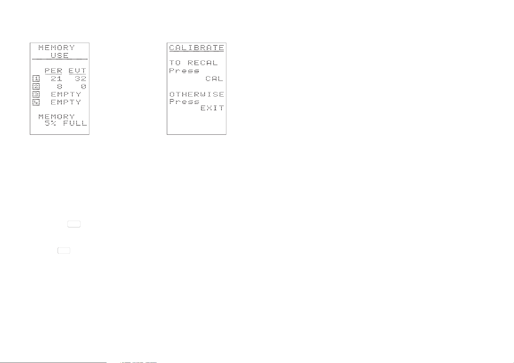
displays the current status of the data stores on a MEMORY USE
screen. This allows the user to see if there is space for the next run, or
whether the contents of a store must first be cleared to make room as
described in Section 1.6. Then the user is offered the choice of recalibrating (i.e performing a field accuracy check) or continuing with the existing calibration settings. If the battery level is too low for reliable
operation, a warning is displayed.
1.4 Field Accuracy Check (Acoustic Calibration)
Either: Press to use the existing calibration settings and proceed
EXIT
directly to the SETUP menu (Section 1.5).
STOP
Or: Press to perform a field accuracy check (acoustic calibration).
CAL
Acoustic calibration of the CEL-268 will normally be performed with a
CEL-284/2 Acoustic Calibrator (IEC 942 Class 1L), while the CEL-368
will use a CEL-282 Acoustic Calibrator IEC 942 Class 2L).
With the CEL-268 and CEL-284/2, carefully fit the calibrator over the
end of the microphone, making sure the microphone is correctly seated
against the shoulder in the calibrator cavity.
Page 4 - CEL-268/368 Operator's Handbook
Shoulder
Shoulder
'O' Ring
'O'-Ring
Microphone
Coupler
Microphone/
Preamplifier Unit
Type 2 Instruments
With the CEL-368 and CEL-282, carefully fit the CEL-4725 Microphone Coupler (supplied with calibrator) over the
end of the microphone/preamplifier
unit, making sure the microphone is
Calibrator
CEL-284/2
or CEL-282
900108
Microphone &
Preamplifier
Type 1 Instruments
correctly seated against the shoulder in
the coupler cavity. Then fit the coupler into into the calibrator, again making sure the coupler is firmly seated against the shoulder in the calibrator cavity.
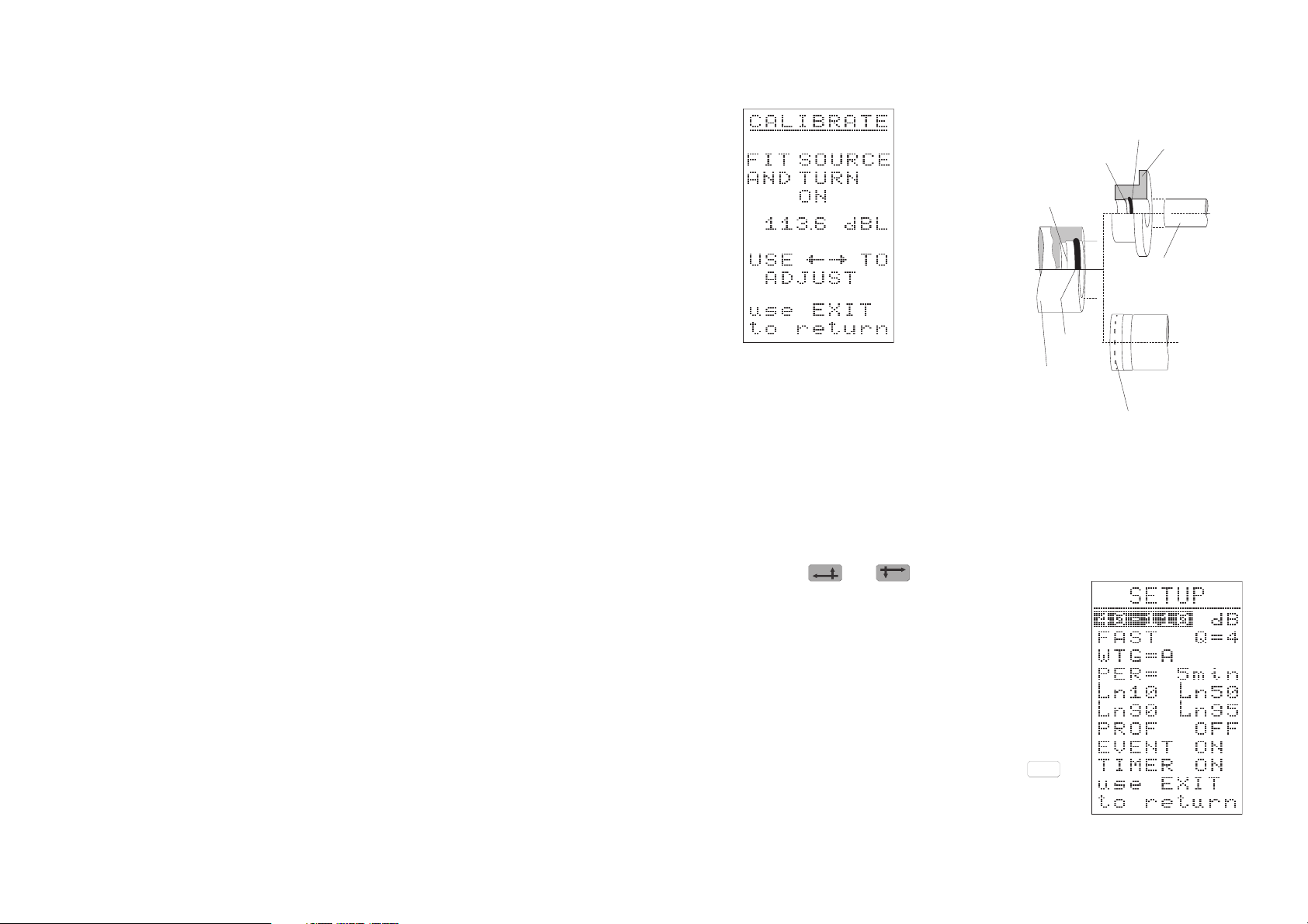
Both calibrators generate a 114.0 dB calibration level at 1 kHz. If necessary, use and to adjust the dis-
played sound value to show the level being
generated by the calibrator.
The level change produced by one press of the
keys is less than the 0.1 dB resolution of the
display, so more than one press may be required to produce a visible change.
Once the correct level is displayed, press
EXIT
to end the calibration sequence and display
the SETUP screen.
CEL-268/368 Operator's Handbook - Page 5
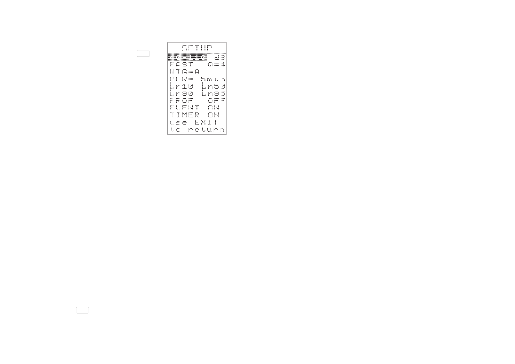
1.5 Use With Current Settings
The SETUP screen shows the current measurement parameters.
Either: Change measurement settings as detailed in Section 1.7 and/or instrument settings
as detailed in Section 1.8.
Or: Press to use the current settings.
EXIT
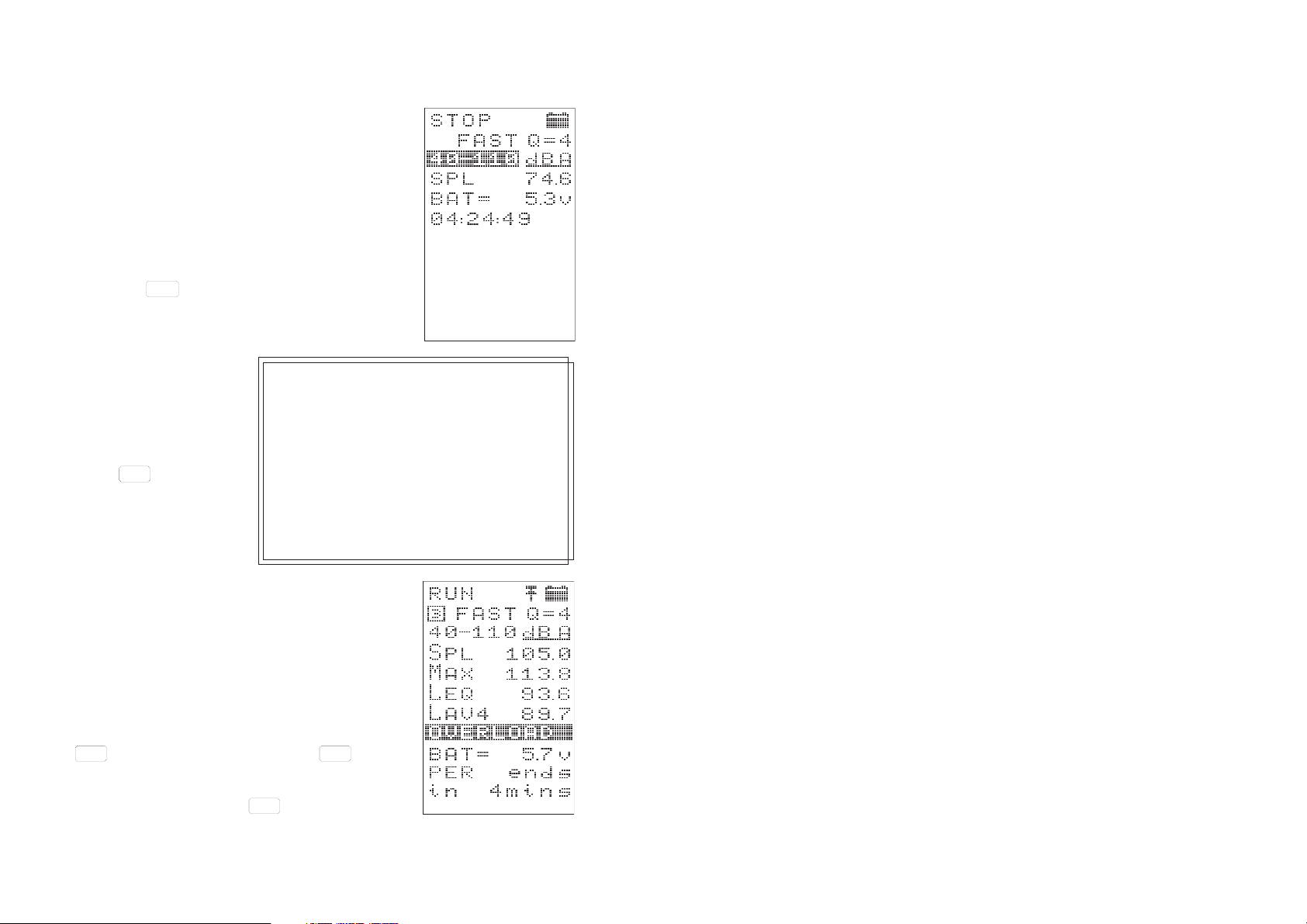
The instrument displays the current measurement status (STOP) on a
"real time" screen showing the instantaneous
sound level, together with
the measurement range
and time weighting in use.
RUN
Press to start to col-
PAUSE
lect data (logging) using
the current settings.
When all data stores are occupied, "NO
MEMORY FOR NEW RUN USE
MEM-DEL" is displayed. Delete data as
described in Section 1.7.
When the timer is set (TIMER shown ON
in the SETUP display), the instrument
waits until the currently set start time
before it starts logging. Similarly, the
instrument will stop automatically when
When there is at least
the current stop time is reached.
one store empty and no
automatic start and stop times have been set,
data collection will start immediately.
The status display changes to show that the instrument is now running.
If it is required to interrupt logging (for example
to eliminate unwanted transient sounds) press
RUN
PAUSE
. Continue logging by pressing again.
RUN
PAUSE
STOP
Stop logging by pressing .
Page 6 - CEL-268/368 Operator's Handbook
CAL
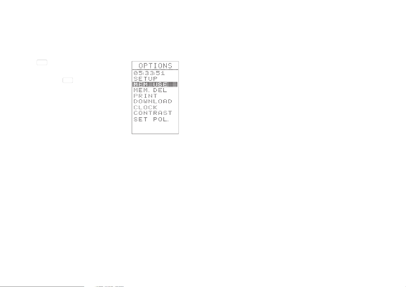
1.6 Checking/Deleting
Memory Contents
When it is required to inspect the memory, or
to delete the contents of one or more stores to
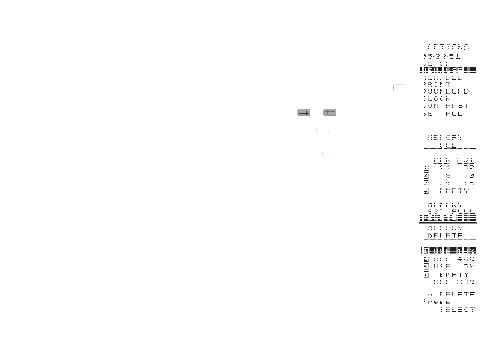
make space for a new logging run, press
to display the OPTIONS menu.
Use and to step to MEM.USE.
OPTIONS
Then press to display the current MEM-
SELECT
ORY USE menu.
Either: Press .to leave this menu and dis-
EXIT
play the current status screen.
Or: Use the DELETE option to show the MEMORY DELETE menu (also reached directly
from the OPTIONS menu.
It is possible to select which store will have its
contents deleted, so that stores containing important data can be saved.
Alternatively, the contents of all stores can be
deleted when the ALL option is used.
1.7 Measurement Parameters
Measurement parameters are accessed via
the SETUP menu displayed after calibration,
when recalibration is declined, or accessed by
using the SETUP option on the OPTIONS
menu (see Section 1.8).
CEL-268/368 Operator's Handbook - Page 7
Move the reverse video cursor to the required
option on the SETUP menu, then press
SELECT
to implement the choice.
The parameters that can be set from this menu
are:
Measurement Range
10-80, 40-110, and
70-140 dB
Time Weighting F (Fast), S (Slow), I
(Impulse),
Q Exchange Rate: 4, 5,
6, or " - " when no L
Avg
is being calculated,
(Plus Q=3 which is not displayed but always in
use for L
eq
),
Frequency Weighting
A, C, and L (Linear),
PER Sampling Period = Interval at which samples
are taken: 1 min, 5 min, 10 min, 15 min, 30 min,
60 min,
L
n
4 results calculated for any user-set value
between L
and L99,
01
PROF Allows profile mode to be switched ON or OFF,
EVENT Allows event mode to be switched ON or OFF,
TIMER Allows logging start and end times to be set ON
or OFF.
PROF (Profile)
Use the PROF option to display the PER. PROF (period profile) menu
that allows the profile mode to be activated.
Depending on the period selected, all FOUR of the profiles indicated
here can be stored. Then, provided at least one profile has been se-
lected ON, when is used to return to the SETUP menu, profile
EXIT
mode will be activated and PROF will be shown ON.
Page 8 - CEL-268/368 Operator's Handbook
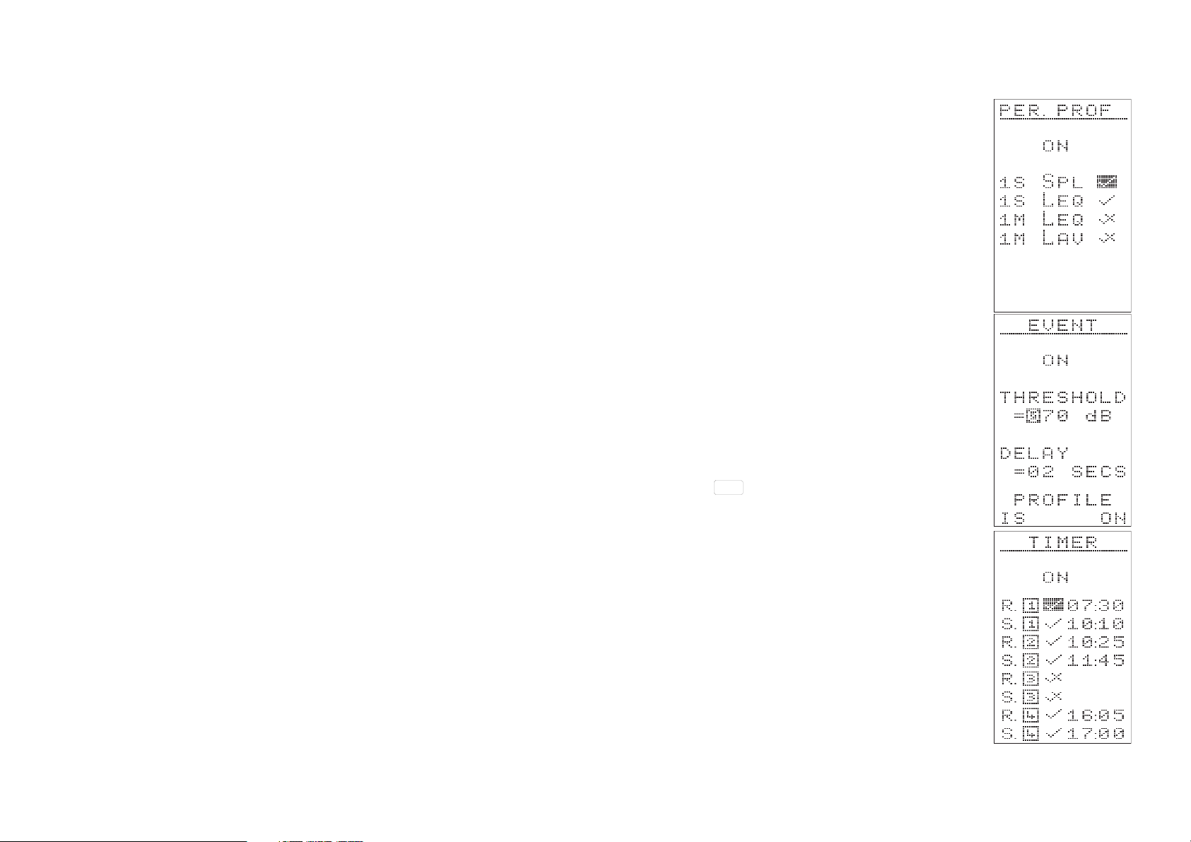
Event ON/OFF
Use the EVENT option to display the EVENT
menu that allows the event mode to be activated.
Some measurement procedures specify that
only sound levels that exceed some pre-determined threshold be included in the measurement. The threshold level can be set to any
value between Ø4Ø and 139 dB.
Similarly, some measurement procedures also
specify that only sound levels that last for more
than some pre-determined period be included
in the measurement. The onset delay time can
be set to any value between ØØ and 3Ø seconds.
When the required threshold and delay values
have been set, and the storing of event profiles
has been switched ON or OFF as required,
press to return to the SETUP menu
EXIT
where EVENT will be shown ON.
Timer ON/OFF
Use the TIMER option to display the TIMER
menu that allows automatic start and end
times for data logging to be specified.
Up to FOUR sets of start and end times can be
specified in the format HH:MM.
Provided at least one timer start and end time
has been set ON, the timer will be activated
when the EXIT key is used to return to the
CEL-268/368 Operator's Handbook - Page 9
SETUP menu and TIMER will now be shown ON.
1.8 Instrument Parameters
OPTIONS
Press .to display the OPTIONS menu that
gives access to the instrument parameters.
Move the reverse video cursor to the required
option, then press to implement the
choice.
The OPTIONS menu can be displayed at any
time, except during the self-verification and calibration sequences. However, when this menu
is displayed while the instrument is logging
data, options that affect any current operation
will NOT be available.
The instrument settings available from this
menu are:
SETUP Displays SETUP menu showing current
MEM. USE Shows memory use (Section 1.6),
MEM. DEL Allows store contents to be deleted (Section 1.6),
PRINT Prints user-selected data set to Centronics
DOWNLOAD Not implemented,
CLOCK Allows instrument date and time to be set,
CONTRAST Allows display contrast to be adjusted,
SET POL. Switches microphone polarization voltage
SELECT
parameter settings (Section 1.7),
compatible printer (Section 1.14),
ON/OFF.
Clock:
This option allows the time and date used by the instrument clock to be
adjusted.
Page 10 - CEL-268/368 Operator's Handbook
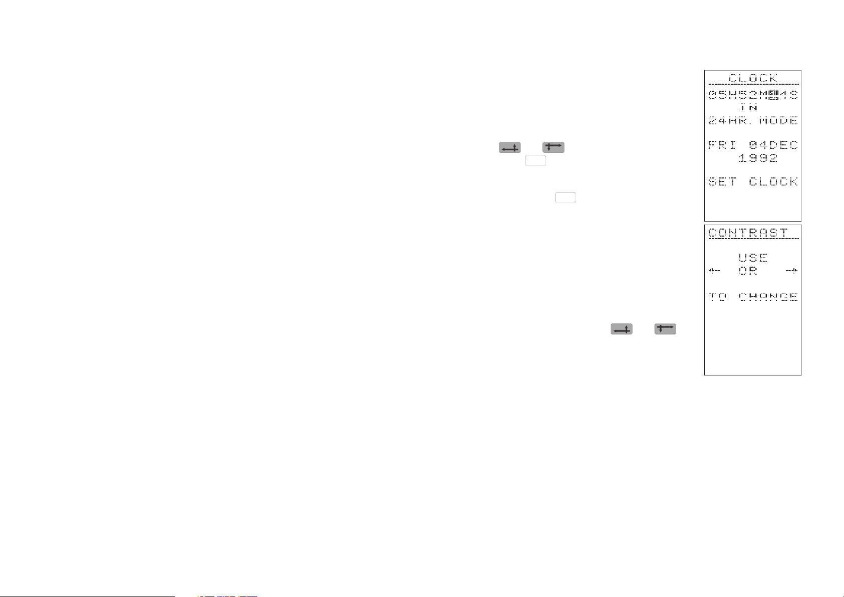
Use the SET CLOCK option to display the
CLOCK menu.
The clock operates only in 24 hour mode with
the day and month in the order shown.
Use and to step from digit to digit
and press to change each digit individu-
SELECT
ally. Then when the required time and date are
displayed, move the cursor to the SET CLOCK
option and press to implement the
SELECT
changes.
Contrast
The display contrast can be adjusted to give
the most convenient viewing, or to suit the current ambient conditions. (LCD contrast may
vary with ambient temperature.)
Use the CONTRAST option to display the
CONTRAST menu. Then use and
to adjust the contrast as required.
Set Pol. (CEL-268 Only)
Warning !
DO NOT connect the 200 V polariztion supply to an
electret microphone - DAMAGE WILL OCCUR.
The 200 V polarizing voltage used with capacitor microphones can be
switched off to allow the CEL-268 to be used with an electret microphone.
Use the SET POL. option to display the SET POL. menu.
CEL-268/368 Operator's Handbook - Page 11
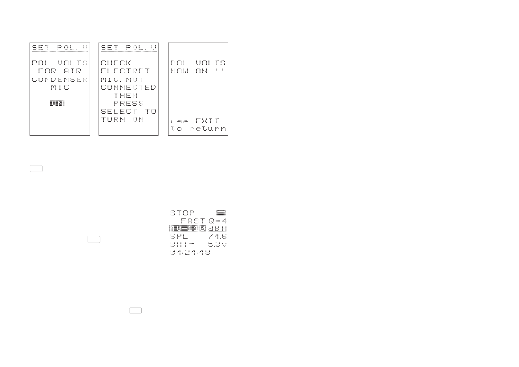
If ON is selected, a warning menu is displayed.
Only when the conditions are correct, follow the instruction and press
SELECT
to switch the voltage ON.
A final advice message confirms that the polarizing voltage is on before
the instrument proceeds to the status display.
1.9 Read Current SPL
The sound pressure level is shown in the current status STOP/PAUSE/RUN "real time" dis-
plays obtained when is pressed to leave
EXIT
the SETUP menu (see Section 1.5).
1.10 Read Cumulative
(Whole Run) Results
Cumulative results for a whole logging run become available only AFTER THE RUN IS
COMPLETE. Either the instrument must have
reached an active timer end time, or must have been used.
STOP
CAL
Page 12 - CEL-268/368 Operator's Handbook
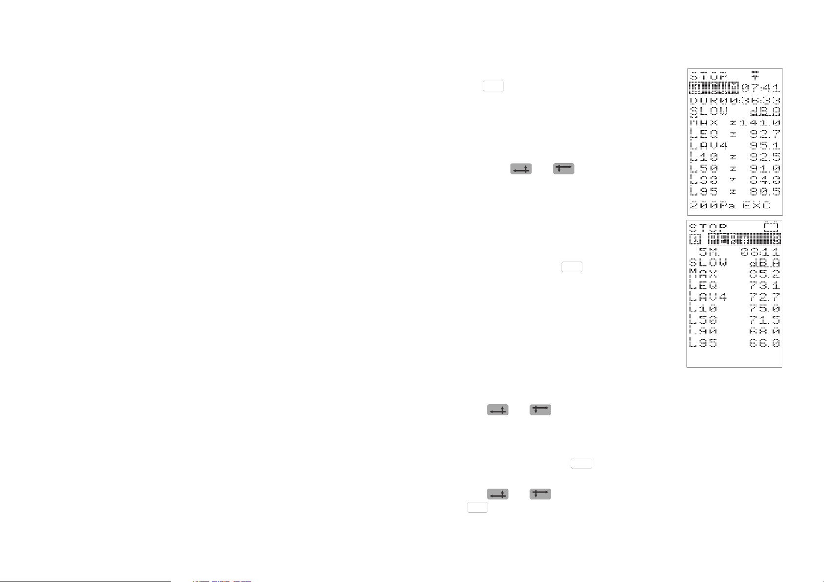
Results can be accessed at any time by press-
CUMUL
ing , EXCEPT during the self-verification
and calibration sequences, or while the instrument is logging data (with RUN indicated as
the current status).
The identity of the STORE in which the results
have been saved is shown in the reverse video
field. Use and to step either way
through the stores to display results for any
other logging run.
1.11 Read Period Results
Period results can be accessed at any time, except during the self-test and calibration se-
quences, by pressing .
When the instrument is logging data, results
for all periods up to but EXCLUDING the current period are available. (Data calculated for a
period becomes available ONLY when the period is complete).
PERIOD
The identity of the STORE (logging run) is
shown and the identity of the PERIOD for
which results are being displayed is shown in the reverse video field.
Use and to step either way through the results to display the
whole period profile saved in THIS store.
When it is required to display period results for a logging run saved in
ANOTHER store, press to display the cumulative results.
CUMUL
Use and to step to the required store identity, then press
PERIOD
to display results for that store.
CEL-268/368 Operator's Handbook - Page 13
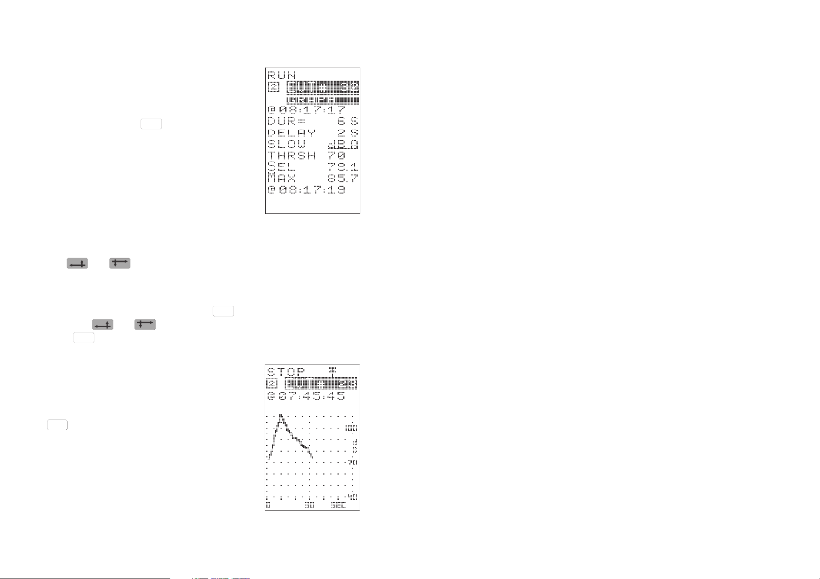
1.12 Read Event Results
Event results can be accessed at any time, except during the self-test and calibration se-
quences, by pressing .
When the instrument is logging data, results
from all events up to but EXCLUDING the current event are available. (Data calculated for
an event becomes available ONLY when the
event is complete).
The identity of the STORE (logging run) is
shown and the identity of the EVENT for which results are being displayed is shown in the upper reverse video field.
Use and to step either way through the events and display
the results saved in THIS store.
When it is required to display the events from a logging run that has
been saved in ANOTHER store, press to display the cumulative results. Use and to display the required store identity, then
press to display results for that store.
EVENT
EVENT
CUMUL
1.13 Inspect Event Graphs
When event profiles have been stored (Section 1.7), they can be displayed by pressing
SELECT
to implement the GRAPH option shown
in the lower reverse video field on the EVENT
screen.
The identity of the STORE (logging run) is
shown together with the identity of the EVENT
(which is shown in reverse video).
Page 14 - CEL-268/368 Operator's Handbook
Use and to move the plot sideways across the display to see
the whole of long profiles.
SELECT
Use to step forward through events and display the profiles saved
in THIS store.
When it is required to display the event profiles from a logging run saved
in ANOTHER store, press to display the cumulative results. Use
and to display the required store identity, press to dis-
CUMUL
EVENT
play results for that store, then use the GRAPH option again.
1.14 Printing Data
When required, a user selectable set of results can be printed on an 80
column Centronics compatible printer connected via a C6590/1.5 Printer
Cable.
For reports that contain only alphanumeric data, most printers usable
with an IBM PC can be used directly without changing their settings.
However, when graphical information is to be included, set the printer
DIP switches as detailed in Section 7.6.
Stored results can be printed at any time, EXCEPT during the self-test
and calibration sequences, or while the instrument is logging data (with
RUN indicated as the current status).
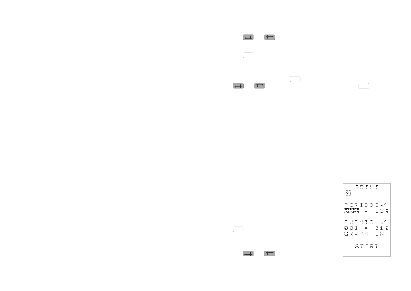
Use the PRINT option in the OPTIONS menu
to display the PRINT menu.
If it is required to print data from a logging run
saved in ANOTHER store, move the reverse
video cursor to the store identity, then press
SELECT
to step to the required store number.
When required, individual or short series of periods and events can be selected for printing.
Use and to highlight the relevant
CEL-268/368 Operator's Handbook - Page 15
field then use to change the indicated number as required.
SELECT
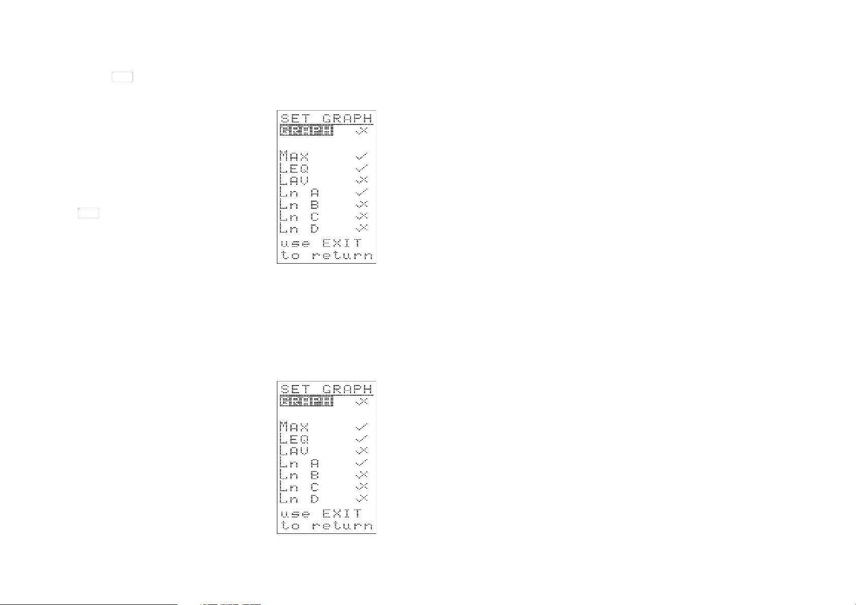
When graphcal printout is required, use the SET GRAPH option to obtain the SET GRAPH menu.
This allows up to THREE functions at a time to
be selected for printing. However, as printing
does not destroy data, repeat printouts may be
made to plot the other parameters as necessary.
Press to return to the PRINT Menu, then
EXIT
use the START option to start the printout.
A message is added to the menu to show that
printing is in progress.
1.15 Downloading Data
All data stored in the CEL-268 and CEL-368 can be downloaded over
an RS 232 Interface to an industry standard PC running CEL-6680
Download Software.
Data transfer is initiated from the PC under the control of the software.
Follow the instructions given on the PC screen.
Use the DOWNLOAD option in the OPTIONS
menu of the noise meter to display the DOWNLOAD display.
This display shows the current download
status, which will change to reflect the progress of data transfer once download is initiated.
Page 16 - CEL-268/368 Operator's Handbook

2. INTRODUCTION
The CEL-268 and CEL-368 Environmental Noise Meters are the first in
a new generation of CEL logging sound level meters designed for environmental noise measurement.
In addition to the usual features found on a full specification sound level
meter, these instruments also provide comprehensive calculation, display and logging facilities that were not previously available in a single
hand held unit. Using well
proven design concepts
and methods that take
full advantage of modern
microprocessor control
and liquid crystal display
technology, they enable a
comprehensive range of
acoustic measurements
to be performed and
stored.
The CEL-268 satisfies the requirements
of IEC 804: 1985 Type 1 and ANSI S1.4
1983 Type S.1* for integrating sound
level meters.
The CEL-368 satisfies the requirements
of IEC 804: 1985 Type 2 and ANSI S1.4
1983 Type S.2 for integrating sound
level meters.
The instruments measure
* With CEL-192/R Random Incidence Microphone
sound pressure levels in
the range from 10 dB(A) to 140 dB(A) at frequencies between 3.5 Hz
and 20 kHz with the microphone supplied, and up to 70 kHz with a suitable microphone.
For example, both frequency and measuring range of the CEL-268 are
1
⁄
extended when an MK-301
" Microphone is fitted to the preamplifier in
4
place of the standard microphone.
Note that there are no facilities for the connection of external filter
sets for frequency analysis of sound and vibration. However, there
is an analog AC output available suitable for FFT or spectrum analysers.
Both instruments have a similar appearance, the main difference being
the separate
1
⁄
" microphone and preamplifier on the Type 1 CEL-268
2
CEL-268/368 Operator's Handbook - Page 17

and the combined
1
⁄
" microphone and preamplifier unit on the Type 2
4
CEL-368. They accept the CEL-3025 Vibration Attachment connected
via a CEL-225/3* (or a CEL-225 Preamplifier) so that vibration levels
can be measured.
2.1 Control & Display
Operations are selected and controlled by extensive menu screens that
are shown on the 9 character x 12 line LCD display which can present
results in both alpha-numeric and graphical format. The combination of
menus and key controls enable the most commonly used parameters to
be selected for measurement and storage.
To minimise setting-up operations, the last used settings are retained
even while the instrument is shut off so that when required, measurement can be started or resumed using only three key strokes. The control software also features comprehensive on-screen instructions and
advice to guide the user through instrument preparation and measurement. This makes it difficult to take measurements with invalid settings.
2.2 Data Storage
Both instruments have four independent data stores numbered 1 4. If
required, a single store
may use the full 60 000
value memory capacity.
ALL results collected
during a logging run (=cumulative period) are
stored together in the
first free data store to allow four complete and
separate sets of measurements to be stored, and the non-volatile memory keeps data safe even while the instrument is switched OFF.
Irrespective of run length, once four
logging runs have been completed, all
four stores become "occupied" to
prevent existing data being overwritten.
No further logging can take place until
the contents of at least one store have
been deleted to make room.
Note* TheCEL-225/3 is supplied with the CEL-268, but must must be ordered
Page 18 - CEL-268/368 Operator's Handbook
separately for a CEL-368.

All results are stored in digital form and are available for downloading to
an industry standard personal computer (PC) for further analysis, data
manipulation, origination of report ready documentation, and permanent
storage. Some stored items may be selected and downloaded directly to
a Centronics compatible printer to produce an immediate hard copy.
2.3 Measurement Modes
Both instruments can operate in three measurement modes simultaneously. Cumulative mode is ALWAYS operational, however data from
either or both period and event modes may also be collected at the
same time. More storage space becomes available whenever one or
more of the measurement
modes is not in use.
Four cumulative runs can be stored.
Cumulative:
Cumulative data is calculated and stored for the
whole of the current logging run (=cumulative period). This also facilitates
the determination of results for periods with nonstandard lengths, and in
practice, results can be
obtained for ALMOST ANY PERIOD. Data can be collected for periods
shorter or longer than the interval set for period mode. The only limitations are due to the manual timing of an interval shorter than one minute, or the availability of power for long term measurements.
Cumulative results (for a whole logging run) become available only AFTER THE RUN IS COMPLETE.
Period:
A series of measurements will be made, and period results calculated
and stored at regular intervals determined and set by the user.
A maximum of 999 period results can be
collected during each logging run.
In addition, up to four profiles can also
be stored during each run.
A maximum of 999 events can be
collected during each logging run.
In addition a 1 sec SPL max. profile of
the first 5 minutes of the event can also
be stored during each run.
CEL-268/368 Operator's Handbook - Page 19

When the period profile option is activated, depending on the period set,
up to four profiles may also be stored (but cannot be shown on the instrument display).
Event:
Events that exceed the user determined threshold level for longer than
the user-set delay can be stored. In addition, a 1 sec SPL Max profile of
the first five minutes of the event can also be saved.
When event profiling has been activated, a 1 sec SPL Max profile of the
first five minutes of the event is stored and may be recalled to the instrument display.
This handbook covers the operation of both
instruments.
Page 20 - CEL-268/368 Operator's Handbook

3. SCHEDULE OF PARTS
A complete "CEL-268 Environmental Noise Meter" consists of the following items:
CEL-268 Type 1 Environmental Noise Meter,
1
⁄
CEL-192
CEL-225/3 Preamplifier.
The following additional items are also included:
040004 Protective Wallet,
LR6 Battery (4 off),
060155 Handbook.
The CEL-192 Microphone can be supplied in a free field (suffix F) or random (R) version to meet the IEC or ANSI standards respectively. The microphone version must be specified with the order.
A complete "CEL-368 Environmental Noise Meter" consists of the following items:
" Measurement Microphone (or equivalent),
2
CEL-368 Type 2 Environmental Noise Meter,
1
⁄
CEL-230
" Microphone and Preamplifier Unit.
4
The following additional items are also included:
LR6 Battery (4 off),
038054 Calibration Trimtool,
060155 Handbook.
When the instrument is delivered, check that all items on the relevant
schedule have been supplied.
Special transit packing is provided for both the instrument and the microphone which must be retained for use when the instrument is transported or will be consigned by general carriers. (Current or pending
CEL-268/368 Operator's Handbook - Page 21

legislation on recycling states that this packaging must be retained for
re-use or be recycled in the locally approved manner). Any instrument
returned inadequately packed to the manufacturers for calibration, service, or repair will be re-packaged and charged accordingly.
The following accessories may be ordered separately to increase the
range of tasks that can be performed by the instrument.
1
⁄
MK-250
" Electret Microphone (for outdoor monitoring
2
or damp conditions with CEL-268),
1
⁄
MK-301
" Condenser Microphone (for increased CEL-
4
268 frequency and measurement ranges),
CEL-216 Line Input Adaptor and Dummy Microphone for
CEL-268,
CEL-316 Line Input Adaptor and Dummy Microphone for
CEL-368,
CEL-282 Class 2L Acoustic Calibrator for CEL-368,
CEL-284/2 Class 1L Acoustic Calibrator for CEL-268,
CEL-2962 Windshield for CEL-268,
CEL-4672/2 Windshield for CEL-368,
CEL-3025 Vibration Attachment, (also needs CEL-225/3
Preamplifier when used with CEL-368),
CEL-3732/2 Mains Power Supply (requires C6592/2 Cable),
CEL-4627 Tripod.
Several special cables are available as follows.
C4493/10 Preamplifier Extension Cable (10 m),
C6591/1.5 Direct connection cable (1.5 m) to Centronics
printer,
C6593/2 12 V DC Power Supply Cable (2 m) with car
cigarette lighter termination,
C6594/2 AC Output Cable (2 m) with BNC termination,
C6605/2 AC Output Cable to Sony TCD D10 DAT
Recorder (2 m), includes event triggering for
suitably modified DAT hand units.
Page 22 - CEL-268/368 Operator's Handbook

These instruments are also available as part of several complete measurement kits. Please contact your CEL representative for details.
CEL-268/368 Operator's Handbook - Page 23

4. DESCRIPTION
4.1 Store Allocation
Both CEL-268 and CEL-368 have a non-volatile data memory to keep
results safe even while the instrument is switched OFF. The memory is
divided into four independent data stores (1 4). When required, any
store may use all of the available storage space up to the full 60 000
value instrument capacity.
All results collected during a logging run are saved in the first available
free store which will then be flagged "occupied" irrespective of the run
duration. Four complete and separate sets of measurements can be
stored in this way without risk of overwriting existing data.
No further logging will be permitted until the contents of at least one
store have been deleted to make room.
4.2 Operating Modes
Both instruments are capable of operating in three substantially independent measurement modes at the same time with results obtained
from each mode being saved in a separate location in the current store.
The instruments ALWAYS operate in both cumulative and period
modes at the same time (even though when the period is set longer
than the cumulative run time, period results are never actually obtained). Simultaneously, results may also be obtained from event mode.
Cumulative:
In cumulative mode measurements are calculated for the whole duration
of the logging run (=cumulative period). This allows results to be determined for periods with non-standard lengths; for example data can be
collected for periods shorter or longer than the intervals which can be
set for period mode.
Page 24 - CEL-268/368 Operator's Handbook

In practice, the main limitations on cumulative duration will be manually
timing an interval shorter than one minute, or the availability of sufficient
memory to store all of the L
values determined during a long term
n
measurement. Memory space is reserved for the cumulative results so
that, provided there is sufficient power, they will always be saved.
Four sets of cumulative results (four logging runs) can be stored, where
results become available only AFTER the run is complete. The following
cumulative information is determined and stored for each run:
• Cumulative store (run) identity,
• Time when cumulative period started (to nearest minute),
• Duration of cumulative period,
• Measurement settings (time and frequency weightings),
• Maximum sound pressure level attained during run (sometimes
known as L
• L
- equivalent continuous level calculated over the duration of
eq
or Ln0value),
max
the whole run,
• Up to four user pre-selected L
• L
- average noise level calculated over the duration of the
Avg
values,
n
whole run with any separately selected Q value,
RUN
• Whether logging has been paused by pressing during
PAUSE
the run,
• Whether 200 Pa level was exceeded during the run (70 - 140 dB
range only),
• Whether overload occurred during the run,
• Whether the battery volts fell below 3.6 V during the run.
Period:
A period interval is always set (even when period data is not required).
In period mode, a series of measurements will be made, and results calculated and stored at regular intervals (periods) set by the user. Periods
of 1 min, 5 min, 10 min, 15 min, 30 min, and 60 min can be set. A maximum of 999 period results can be collected during each logging run, and
CEL-268/368 Operator's Handbook - Page 25

in addition, a profiling option can be activated to store up to four period
profiles.
The following period information is determined and will be stored for all*
periods during the run:
• Cumulative store (run) identity,
• Period identity,
• Period interval,
• Start time of period to nearest second,
• Measurement settings (time and frequency weightings),
• Maximum sound pressure level attained during period (some-
times known as L
- equivalent continuous level calculated over period,
• L
eq
• Up to four user pre-selected L
• L
- average noise level calculated over period with any
Avg
or Ln0value),
max
values,
n
separately selected Q value,
RUN
• Whether logging has been paused by pressing during
PAUSE
the period,
• Whether 200 Pa level was exceeded during the period
(70 - 140 dB range only),
• Whether overload occurred during the period,
• Whether the battery volts fell below 3.6 V during the period.
When the profile option has been switched ON, the following additional
information may also be stored (but cannot be shown on the display):
• 1 sec Max profile - when period is set to either 1 or 5 minutes,
• 1 sec L
• 1 min L
• 1 min L
profile - when period is set between 1 and 5 minutes,
eq
profile - when period is set between 5 and 60 minutes,
eq
profile - when period is set between 5 and 60 min-
Avg
utes,
RUN
• Whether logging has been paused by pressing during
PAUS E
the profile,
• Whether 200 Pa level was exceeded during the profile
(70 - 140 dB range only),
Page 26 - CEL-268/368 Operator's Handbook
Note* Ifthe instrument reaches the end of a cumulative run beforethe current period
has ended, as the results for the current period are still incomplete, no data will
be saved for this period and the results lost.