

Casella CEL CEL-360S User Manual

Instructions specific to hazardous area
installations
(reference European ATEX Directive
94/9/EC, Annex II, 1.0.6.)
The following instructions apply to equipment covered by certificate
number Sira 05ATEX2027X for the CEL-320/IS and CEL-360/IS:
1 The equipment may be used with flammable gases and vapours
with apparatus Groups IIA, IIB and IIC and with temperature
classes T1, T2, T3 and T4.
2 The equipment is only certified for use in ambient temperatures in
the range -20oC to +40oC and should not be used outside this
range.
3 The certificate marking is detailed on drawing numbers
13-1920001A/IS-03 and 13-1920002A/IS-03.
4 Repair of this equipment shall be carried out by the manufacturer
or in accordance with the applicable code of practice.
5 The certification of this equipment relies on the following
materials used in its construction: Polybutylene terephlhalate
(PBT) and Polycarbonate (PC)
If the equipment is likely to come into contact with aggressive
substances, then it is the responsibility of the user to take
suitable precautions that prevent it from being adversely
affected, thus ensuring that the type of protection is not
compromised.
Aggressive substances e.g. solvents that may affect polymeric
materials
Suitable precautions e.g. regular checks as part of routine
inspections or establishing from the material’s data sheet that it
is resistant to specific chemicals.
6 The certificate number has an ‘X’ suffix that indicates that the
following special condition of certification applies;
Under certain extreme circumstances, the non-metallic parts
incorporated in the enclosure of this equipment may generate an
ignition-capable level of electrostatic charge. Therefore, when it
is used for applications that specifically require group II, category
1 equipment, the equipment shall not be installed in a location
where the external conditions are conducive to the build-up of
electrostatic charge on such surfaces. Additionally, the
equipment shall only be cleaned with a damp cloth.
CEL-320/360 Getting Started - Page 1

Page 2 - CEL-320/360 Getting Started
CEL-320/360 SERIES
01038
ta
e
its
d
g
e
ys
d
Issue: 2
If you want to get on and use the instruments without any background
information, skip Sections 3 - 5 and go straight to Section 6.
USERS GUIDE
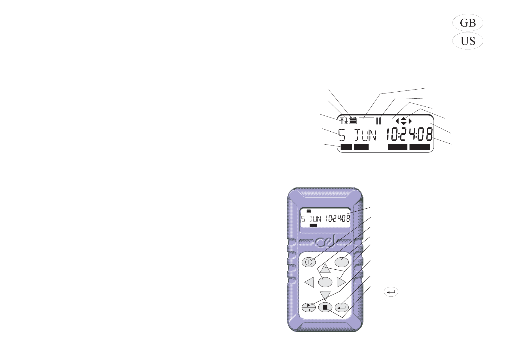
1. Display
Battery Condition
Under range has
Occurred
Overload has
Occurred
Measurement
Identity or Date
Current Mode,
Pressing the MENU
key will select each
of these in turn
REC
SLM DATA SET UP OPTION
CA
Data is Being Recorde
Measurement is Pause
Frequency Weightin
dB%
01037e
Indicates Activ
Option Ke
Current Un
Current Da
or Tim
2. Keys
Display
Switches instrument ON/OFF
DATA
DATA
MENU
Changes operating mode
Accesses stored data
Select active options from the current
menu
Starts/Pauses/Restarts a measurement
record
Confirms actions of other keys
Stops a measurement when followed
by
CEL-320/360 Getting Started - Page 3

3. Contents
Section . . . . . . . . Page
1 Display . . . . . . . . . . . 3
2 Keys . . . . . . . . . . . . 3
3 Contents . . . . . . . . . . 4
4 Introduction to the
Dosimeters . . . . . . . . 4
4.1 Sound Level Meter Models 5
4.2 CEL-320/320S Noise
Dosimeters . . . . . . . 5
4.3 CEL-360/360S Logging
Noise Dosimeters . . . . 6
5 Preparation for Use . . . . 7
5.1 Install Battery and
Microphone . . . . . . . . 7
5.2 Perform Acoustic Calibration 7
6 Operation as a Dosimeter . 9
6.1 Select Dose Set Up for Use 9
6.2 Measure and Store
Dose Data . . . . . . . . 9
6.3 Recall Dose Data . . . . . 10
Section . . . . . . . . Page
6.4 Review Stored Data . . . . 10
6.5 Print Standard Report . . . 11
7 Operation as a Sound Level
Meter ...........12
8 Selecting and Changing
Options ..........13
8.1 Review Options . . . . . . 13
8.2 Set Time & Date . . . . . . 14
8.3 Change Timer and Run
Duration (CEL-360 Series) . 14
9 Technical Information . . . 16
9.1 Specification . . . . . . . . 16
9.2 CE Compliance . . . . . . 18
9.3 Default Parameter Settings 18
9.4 Parameter Identities . . . 19
10 Parts, Servicing & Warranty 20
10.1 Schedule of Parts . . . . . 20
10.2 Servicing &
Warranty Arrangements . . 20
11 Intrinsically Safe Models . 22
4. Introduction to the Dosimeters
The CEL-320 and CEL-360 Noise Dosimeters have been developed from
the successful CEL-420/460 range of instruments by adding features and
improving the control procedures. They measure the frequency weighted
noise exposures and peak sound levels simultaneously.
The dosimeter microphone and lead on both models can be replaced by
a sound level meter microphone to offer comprehensive sound level
measurement. The CEL-320/360 series instruments have the following
features.
¤ Seven built-in standard dose measurement setups:
OSHA, MSHA, DOD, ACGIH, ISO85*, ISO90* and METER
¤ Up to 13 user specified dose measurement setups,
¤ A single sound level meter (SLM) setup,
¤ 50 dose (DATA) result stores,
¤ Storage of up to 10 profiles attached to each CEL-360 dose
measurement, as specified by dB10 or dB12 software,
¤ Self configured storage.
The instruments are built to withstand rough industrial conditions with
cases formed from a polyester/polycarbonate material that gives them a
Note*: ISO procedures using Criterion 85 dB and 90 dB.
Page 4 - CEL-320/360 Getting Started

high resistance to damage. Data integrity is further protected by a dose
microphone lead which is designed to resist knocks and abrasions
without affecting the signal passing from microphone to instrument.
Both instruments can be operated and deliver dose and SLM
results without the need for other equipment, beyond an acoustic
calibrator. However, they become even more versatile when their
measurement and setup data is transferred via a PC using the CEL-6702
dB10 or CEL-6704 dB12 Windows™ based software.
These programs enable the instruments to be fully configured.
Dose (DATA) setups can be added or removed from the instrument,
while the individual measurement parameters can be added, deleted or
changed in a setup. Some setup parameters, such as measurement
range, can either be set to a particular value or left to the user to change
via the instrument keypad.
dB10 and dB12 have the facilities expected of fully featured 32
TM
bit Windows
packages, enabling report production with cut and paste
between applications and comprehensive word processing capabilities.
In addition, dB12 has extensive on screen graphing facilities.
4.1 Sound Level Meter & Intrinsically Safe (IS) Models
Both dosimeters can be converted to a miniature sound level meter by
fitting a CEL-425 SLM Microphone Adaptor. The CEL-320 becomes a
CEL-320S Sound Level Meter,
while the CEL-360 becomes a
CEL-360S Logging Sound Level
Meter.
For sound level meter
operation refer to Section 7.
Intrinsically safe versions
Table 1: Models Available
Standard
Model
CEL-320 Noise Dosimeter
CEL-320S Sound Level Meter
CEL-360 Logging Noise Dosimeter
CEL-360S Logging Sound Level Meter
Description
are available of both dosimeter
and sound level meter models.
The part numbers have “/IS” after their standard part number. The
model line up is shown in Table 1.
4.2 CEL-320/320S Noise Dosimeters
The following features apply to the CEL-320 and CEL-320S. These
instruments are ideal for quick on-site surveys and for monitoring
personal noise exposure in accordance with European ISO or USA
OSHA, MSHA, DOD and ACGIH standards.
For dose measurement, they are passive instruments with
settings that may be reviewed by key strokes, but which can be selected
only by means of the dB10 or dB12 software.
CEL-320/360 Getting Started - Page 5

However, all sound
level measurement
parameters can be set from
the keypad. There are three
overlapping measurement
ranges: 30 - 100, 50-120 &
70-140 dB, A & C RMS
weightings, Linear & C Peak
weightings, Fast, Slow &
Impulse time weightings, and
energy exchange rates (Q) of
3, 4, 5 & 6. In dose measurement mode, they display %
dose, % dose projected for
an 8 hour period, peak level
Table 2: Setups and Configuration Files
Parameter settings that do not modify preset
measurement protocols can be changed by using
the instrument keys.
All available parameter settings can be changed
from a PC by means of dB10 or dB12 Software.
Parameter settings that modify preset measurement protocols must first be saved by dB10 or
dB12 under a new setup identity in an instrument
“configuration file”.
A “configuration file” contains a complete
instrument set of setups, i.e. seven fixed dose
setups, up to 13 user defined setups, one SLM
setup, and one timer setup common to all dose
setups.
Parameter settings on an instrument can be
changed ONLY by using dB10 or dB12 to replace
the configuration file in the instrument by another
configuration file loaded from the PC.
and measurement duration.
For countries that are subject to European Union regulations or
the equivelent ISO standards, these instruments measure the daily
sound exposure level (L
identical with the L
EX,8h
Aeq,8hr
Pa2h according to IEC 1252, which is
required by ISO 1999), while for USA
OSHA/MSHA regulations they measure the Time Weighted Average
level (TWA).
When used as a sound level meter they display sound level,
maximum sound level, minimum sound level, peak, time-averaged (L
or L
) sound levels and sound exposure level (SEL).
Avg
Aeq
4.3 CEL-360/360S Logging Noise Dosimeters
In addition to the features available to the CEL-320 Dosimeters, the
following additional features apply to the CEL-360 and CEL-360S. These
instruments are recommended for detailed measurements as they
include extended processing and memory functions.
There are automatic run timing facilities controlled by the built-in
clock and time-history recording capabilities that allow up to 10 profiles
to be saved with each dose (DATA) result set, in a separate profile store.
Sampling times can be specified between 1 s and 1 hour by dB10 and
dB12 software, while profile storage is in excess of 220 000 data points,
where any single run can use up to 99 999 points.
The instruments are able to measure and save up to five user
specified L
specified via instrument keys, by dB10 or dB12, and start and stop times
preset via dB10 or dB12 can be switched on or off from the instrument
keys. Other settings can be changed only by dB10 and dB12 Software.
values (exceedance level percentiles). Run durations
n
Page 6 - CEL-320/360 Getting Started
Once data saved by a CEL-360 instrument has been downloaded
e
to a PC, the user can specify a period over which to re-calculate the
projected % dose values. The software can also calculate six
exceedance time percentiles with levels preset to values specified by
measurement standards, plus one user specified time percentile.
5. Preparation for Use
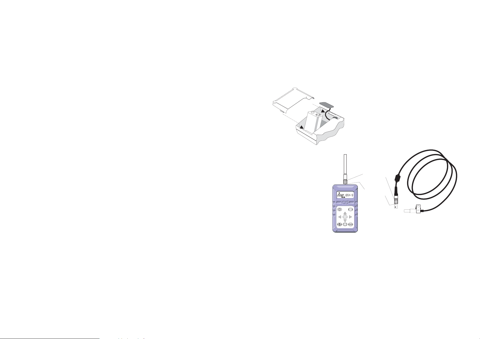
5.1 Install Battery & Microphone
Connect a new 6LF22 or equivalent 9 V
battery to the terminals in the battery
compartment in the rear of the instrument.
DO NOT disconnect the battery
once runs have been stored as they
will be lost !
With the instrument switched
OFF, insert the lead connector of the
960079
CEL-6681 Dosimeter Microphone or the
connector on the
CEL-425 SLM Adaptor
stalk into the socket
on the top end of the
case with the red dot
facing the front of the
dosimeter.
Remove the
connector ONLY by
pulling on the knurled
sleeve.
CEL-425
SLM Adaptor
Knurled
Red "Dot"
DATA
MENU
SET
STOP
ENTER
Sleeve
CEL-6681
Dosimeter Microphon
01042e
5.2 Perform Acoustic Calibration
Operations are controlled by a sequence of key strokes.
Perform a field accuracy check each time the instrument is
switched ON using a CEL-110/2 (Class 2) or CEL-110/1 (Class 1)
Calibrator as follows. It is also recommended that another acoustic
calibration be performed immediately after completing a measurement
run.
The calibration levels from both before and after are stored with
the run. When the second calibration occurs much later, provided the
same microphone assembly is used, the second level is attached to any
stored run that has no second calibration.
CEL-320/360 Getting Started - Page 7
Calibrator
980057
'
er
e
Fit the CEL-4726 Coupler
supplied with the calibrator (CEL-110/1 or
110/2 ) into the calibrator cavity, making
sure it is firmly in contact with the
shoulder in the cavity. (To aid removal,
the coupler flange does not fit close
against the calibrator housing).
O'Ring
Fit the microphone into the
coupler cavity, again ensuring that it
makes contact with the shoulder in the
coupler cavity.
Then follow these instructions.
1/4"
Microphone
Operation Press Display Shows Comments
1. Switch the
instrument
ON
2. Change
Operating
Mode
3. Enable
Level
Change
4. Change
Indicated
Level
5. Set
Calibration
Level
6. If the
calibration is
to be aborted
MENU
repeatedly
or
DATA
Start Up messages show:
Instrument Type,
Serial Number (when set),
Print (when printer cable
connected),
Firmware Version,
finishing with the Last Used
Operating Mode.
To select OPTION, to enable
Acoustic Calibration, it shows
current SPL.
OPTION
and are now enabled.
The display shows current
sound level.
OPTION
Press or .
Indicated level rises (falls)
0.05 dB for each key press.
Adjust to correct level for
OPTION
CEL-320/360 microphones at
standard temperature and
pressure: 114.0 dB.
The 114.0 dB calibration level
is now set, and will be stored
in the microphone assembly.
OPTION
The calibration level is
NOT SAVED and the
instrument continues to use
the last saved calibration.
OPTION
Should
Microphon
Coupler
Page 8 - CEL-320/360 Getting Started
 Loading...