

Casella CEL CEL-310 User Manual

CEL-310 DOSE BADGE
&
CEL-315 READER UNIT
Users Handbook
060349/HB-01
May 2003
CASELLA CEL
Regent House
Wolseley Road
Kempston, Bedford
MK42 7JY U.K.
Phone: +44 (0)1234 844 100
Fax: +44 (0)1234 841 490
E-Mail: info@casellacel.com
Web: www.casellacel.com
CASELLA USA
17 Old Nashua Road #15
Amherst
NH 03031
U.S.A.
Toll Free: +1 800 366 2966
Fax: +1 603 672 8053
e-mail: info@casellausa.com
Web: www.casellausa.com

Caution
Store the Dose Badge in Stop Mode and ONLY
in a fully charged state. To ensure optimum
operation, the Dose Badge should be left on
trickle charge when not in use.
To avoid accelerated power loss DO NOT store
the Dose Badge in an area with a high ambient
lighting level.
DAMAGE WILL OCCUR if discharged batteries
are left in the Dose Badge or in the Reader
Unit.
Avoid damage by checking the battery charge
state every 2 weeks (14 days).
Caution !
Recharge the battery in the Dose Badge only
with the battery charger supplied.
Return the Dose Badge to Casella CEL or an
authorised service centre for replacement of
the internal battery after 12 months from the
date of supply.
It is recommended that the instructions and
information contained in this handbook be
read before operating the equipment.
Page 2 - CEL-310 Dose Badge Users Handbook

Contents
Contents
Chapter ................... Page
1. INTRODUCTION . . . . . . . . . . . . . . . . . . . 5
1.1 The System ...................... 6
1.2 Layout & Controls ................... 7
2. PREPARATION . . . . . . . . . . . . . . . . . . . 9
2.1 Unpack the Equipment ................ 9
2.2 Quick Start ...................... 9
2.3 Charge the Dose Badge Battery ...........10
2.4 Insert Batteries into the Reader Unit .........12
2.5 Switch the Reader Unit ON & Check Configuration . 12
3. CONFIGURE THE READER UNIT . . . . . . . . . . 16
3.1 Set the Clock .....................16
3.2 Configure History Measurement ...........17
3.3 Configure Criterion Time ...............17
3.4 Configure Criterion Level ...............18
3.5 Configure Dose Badge Settings ...........19
4. OPERATION . . . . . . . . . . . . . . . . . . . . 20
4.1 Automatic Calibration .................20
4.2 Reset the Dose Badge ................21
4.3 Wearing the Dose Badge ...............22
4.4 Start Measurement ..................23
4.5 Stop Measurement ..................24
4.6 Download Measurements to the Reader Unit ....25
4.7 Print Stored Measurements .............26
4.8 Review Stored Measurements ............27
4.9 Download Measurements to a PC ..........28
4.9.1 Install the Software ..................29
4.9.2 Download Measurements from Reader to PC ....29
CEL-310 Dose Badge Users Handbook - Page 3

Contents
Chapter ................... Page
5. ROUTINECARE ..................31
5.1 Annual Verification .................. 31
5.2 Cleaning .......................31
5.3 Storage ........................ 31
6. TROUBLESHOOTING . . . . . . . . . . . . . . . . 33
6.1 Reader Unit Troubleshooting ............. 33
6.2 Dose Badge Troubleshooting ............ 34
6.3 Charger Troubleshooting ............... 34
7. TECHNICAL INFORMATION . . . . . . . . . . . . 36
7.1 Specification ..................... 36
7.2 Ordering Information ................. 38
8. SERVICE & WARRANTY . . . . . . . . . . . . . . 39
A1 APPENDIX 1 - Glossary . . . . . . . . . . . . . . 41
Page 4 - CEL-310 Dose Badge Users Handbook
Introduction
1. INTRODUCTION
The CEL-310 Dose Badge is a unique solution to problems associated
with the measurement of personal noise exposure. It is controlled and
downloads data via infrared signals and in consequence needs no
external controls or cables. This allows it to be used in situations where
the wearer is working in confined spaces, or where there is a risk of
cables becoming caught in machinery.
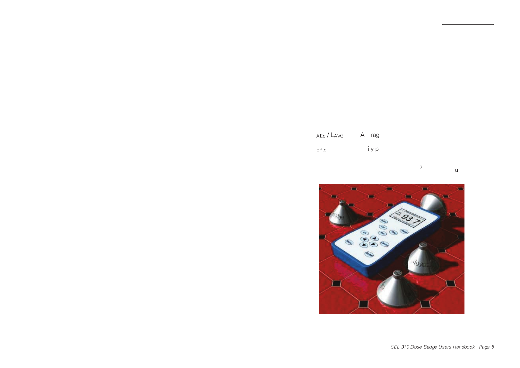
The Dose Badge can be configured to make measurements
according to ISO or OSHA standard, where it provides the following
information.
Run time Duration of the measurement,
L
AEq/LAVG
L
/ TWA Daily personal noise exposure,
EP,d
% Dose Noise exposure as a percentage of a preset
Exposure Sound exposure in Pa
Peak Exceeded Whether 140 dB(C) Peak has been exceeded.
Average sound pressure level during the
measurement period,
total,
2
h (Pascal squared hours),
Figure 1: Dose Badges and the Reader Unit
CEL-310 Dose Badge Users Handbook - Page 5

Introduction
The system is delivered with the Dose Badge configured for
either ISO or OSHA measurement. The user can change the configuration
by means of the Reader Unit, allowing the Dose Badge to be altered for
different Standards and Guidelines. A system may be founded with a
single Dose Badge and Reader, then expanded by adding further Dose
Badges and an appropriate number of chargers.
This manual describes the operation of the Dose Badge, Reader
Unit and Windshield.
1.1 The System
A Dose Badge system consists of a number of individual Dose Badges
controlled by a single Reader Unit. The Reader provides the method to
calibrate, start, stop and download measurements from a Dose Badge,
then download this information to a PC.
The system can be configured to measure according to ISO or
OSHA standards.
Those authorities who follow European Union measurement
procedures should use the ISO configuration. This satisfies the
requirements of IEC 61252 and employs the following settings.
Q = 3 Energy exchange rate,
80 dB Threshold level,
85 dB Criterion level,
8 hours Criterion time,
Freq. weighting A for all sound level measurements,
C for peak sound pressures,
Time weighting None.
Those authorities who follow U.S. measurement procedures
should use the OSHA configuration. This satisfies the requirements of
ANSI S1.25-1991 and employs the following settings.
Q = 5 Energy exchange rate,
80 dB Threshold level,
90 dB Criterion level,
8 hours Criterion time,
Freq. weighting A for all sound level measurements
C for peak sound pressures,
Time weighting Slow weighting.
Page 6 - CEL-310 Dose Badge Users Handbook
M
Introduction
When a measurement is downloaded from the Reader to the
Dose Badge Software, the configuration of the Dose Badge is shown.
PLEASE NOTE that the Microphone Response shown as “F”
does not indicate Fast time weighting, but rather Free Field microphone
response.
The Reader controls the Dose Badge via an infrared link with
information sent backwards and forwards in a similar way to a television
remote control.
PLEASE NOTE that the range of communication is very much
shorter than a television remote control.
Each Dose Badge contains a rechargeable battery, where a
single charge of the battery is intended to supply sufficient power for a
measurement lasting up to 16 hours. However, the Dose Badge can run
for much longer when the battery is fully charged.
1.2 Layout & Controls
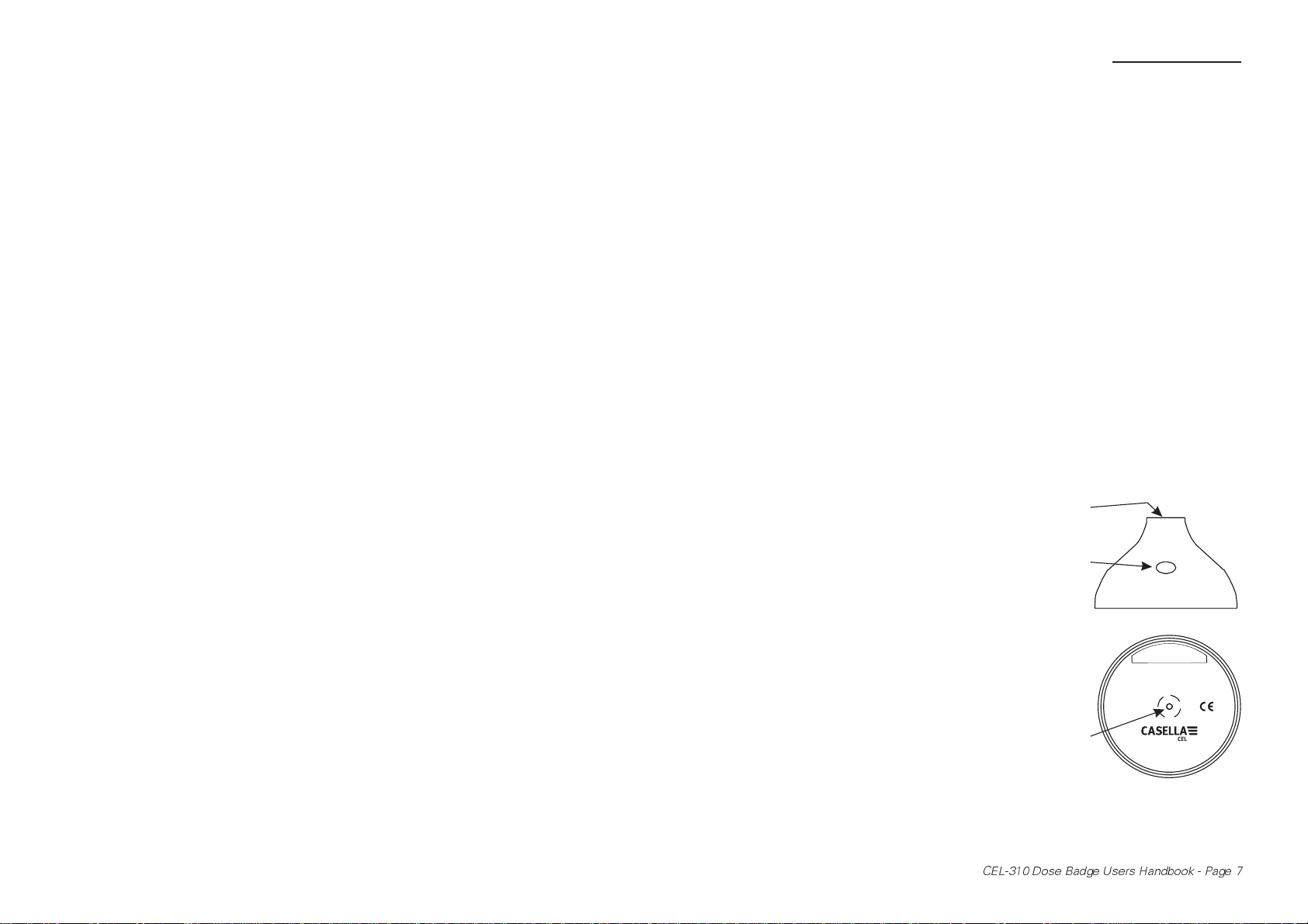
The layout of the Dose Badge is shown in Figure 2.
The microphone is mounted at the top of the case in a shock
mount that reduces the noise generated from movement or handling.
A window allows access for
the infrared control signals from the
Reader Unit. Ensure that this window
is clean and free from dust and dirt.
The charging connection for the
internal battery is at the centre of the
bottom panel. This threaded insert is
also used to attach the Dose Badge.
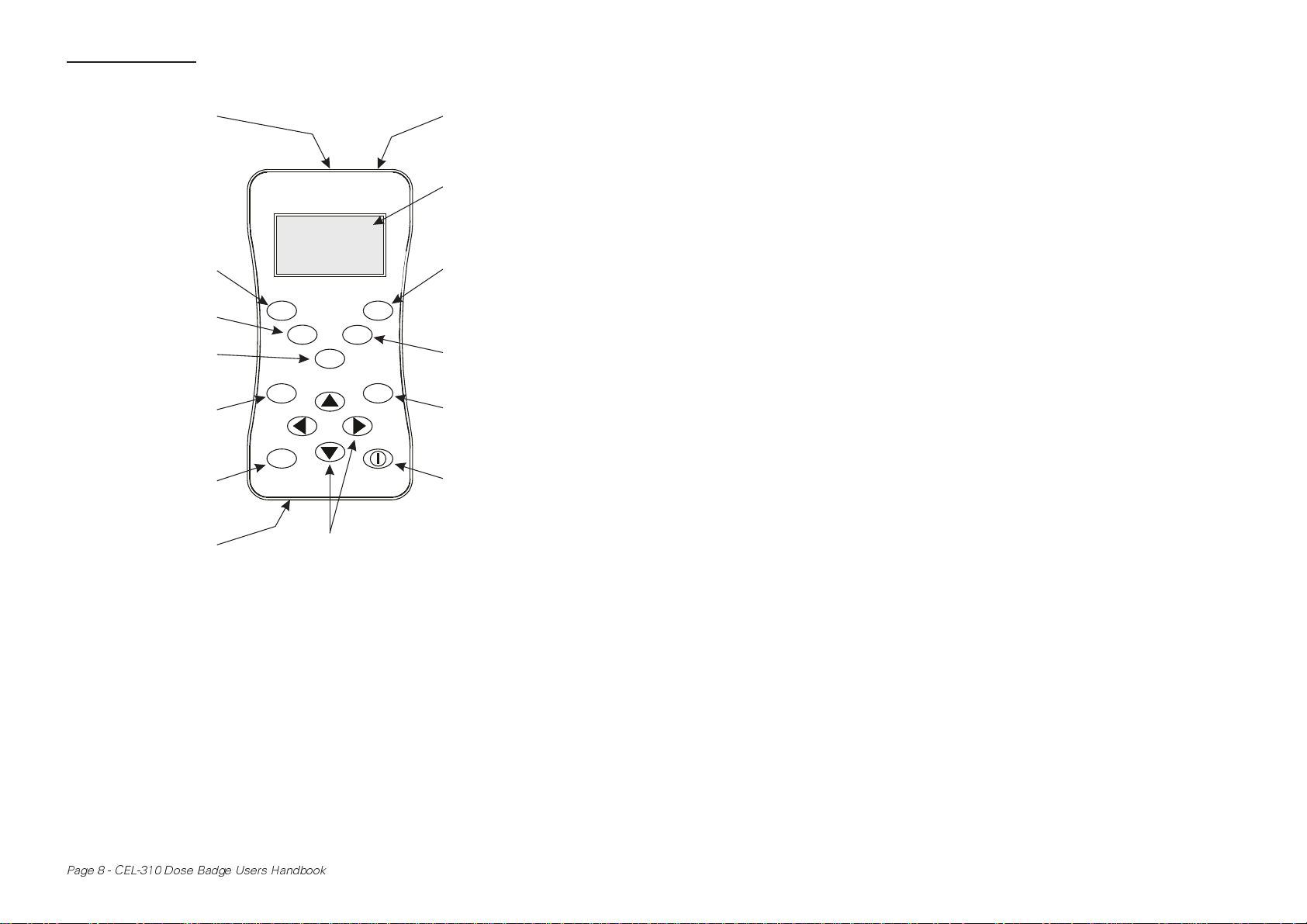
The Reader Unit, shown in
Figure 3, has an integral acoustic
calibrator that has been specifically
designed to suit the unique shape and
performance of the Dose Badge. The
calibrator cavity is located in the top
panel of the Reader.
icrophone
Infrared
window
0000
Serial Number
CEL-310
ANSI S1.25-1991Class: see manual
or IEC 61252: 1993
Charging/
mounting
stud
www.casellacel.com
03002
Figure 2: The Dose Badge
CEL-310 Dose Badge Users Handbook - Page 7
Introduction
Acoustic calibrator
in centre of top panel
Reset Dose Badge
Calibrate Dose Badge
Start Dose Badge
measurement
Accept changes &
select options
Display menu
RS232 connector to
side of bottom panel
03001
Dose Badge Reader
Reset
Cal
OK
Menu
Read
Stop
Run
Cancel
Navigator keys to select/change/enter data/
step through information shown on the display
Figure 3: The Reader
Infrared window to
side of top panel
Display
Read measurement
from Dose Badge
Stop Dose Badge
measurement
Cancel & exit from
menu
Power On/Off
An infrared port beside the acoustic calibrator in the top panel, is
used to communicate with the Dose Badge. Ensure that this window is
clean and free from dust and dirt.
The RS232 connector used to download data to a PC is located in
the bottom panel of the Reader, while the battery compartment is located
in the rear panel.
Page 8 - CEL-310 Dose Badge Users Handbook

Preparation
2. PREPARATION
It is recommended that the instructions and information contained in this
handbook be read before operating the equipment.
2.1 Unpack the Equipment
Carefully remove all components of the Dose Badge system from the
shipping container or carrying case and inspect them for possible damage
or missing items. If there appears to be damage or something missing,
please contact Casella CEL or your local representative immediately. The
following components should be included.
CEL-310 Dose Badge,
CEL-315 Dose Reader Unit,
C6801/2 RS232 Cable (2 m),
-PC18 Mains Power Supply (with UK, EU or USA plug
as ordered,
CEL-6802 Mounting Kit for Dose Badge consisting of
Blank Mounting Plate,
Mounting Plate with Safety Pin Attachment,
Leather Mounting Patch,
Windshield,
Safety Pins (x2).
CEL-6803 Hard Hat Mounting Kit,
CEL-6804 dBLink Dose Badge Software on a CD,
CEL-6805 dBDatabase Software (ordered separately),
CEL-6806 Carrying Case for Dose Badge System with
up to 10 Badges,
060349/HB Operating Manual.
At least one of the following items will also be supplied as ordered
CEL-6807/2 Charger for 2 Dose Badges,
CEL-6807/5 Charger for 5 Dose Badges,
CEL-6807/10 Charger for 10 Dose Badges.
Please check that any other components that were ordered have been
included with the equipment.
2.2 Quick Start
This is the recommended procedure for performing personal sound
exposure measurements using a single Dose Badge and Reader.
1. Charge the Dose Badge battery (Section 2.3).
CEL-310 Dose Badge Users Handbook - Page 9
Preparation
2. Insert usable batteries into the Reader Unit (Section 2.4).
3. Use the Reader menu to check that the configuration set for
the Dose Badge is suitable for the proposed measurements
(Section 2.5).
4. Insert the Dose Badge into the calibration cavity on the Reader
(Section 4.1).
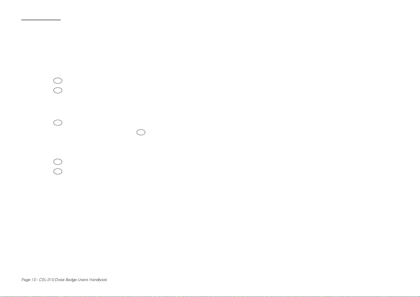
5. Press to reset the Dose Badge (Section 4.1).
6. Press to calibrate the Dose Badge automatically (Section 4.1).
7. Use the Reader to reset the Dose Badge (Section 4.2).
8. Remove the Dose Badge from the calibration cavity and attach
9. Press to start the measurement (Section 4.4).
10. At the end of the measurement shift, press to stop the run
11. Remove the Dose Badge from the wearer and push it into the
12. Press to perform a second calibration check (Section 4.1).
13. Press to transfer the Dose Badge session data to the Reader
14. View the results (Section 4.8) and print a hard copy (Section 4.7).
15. Download measurements to the PC software (Section 4.9).
Reset
Cal
it to the wearer (Section 4.3).
Run
Stop
(Section 4.5).
calibration cavity on the Reader (Section 4.1).
Cal
Read
via the infrared link (Section 4.6).
2.3 Charge the Dose Badge Battery
The Dose Badge contains a rechargeable battery pack which is NOT
USER REPLACEABLE.
The indicators on the Dose Badge charger show the following
states:
Red Flashing Dose Badge not connected,
Red Constant Low battery,
Green Flashing Charging cycle,
Green Constant Trickle charging.
Page 10 - CEL-310 Dose Badge Users Handbook
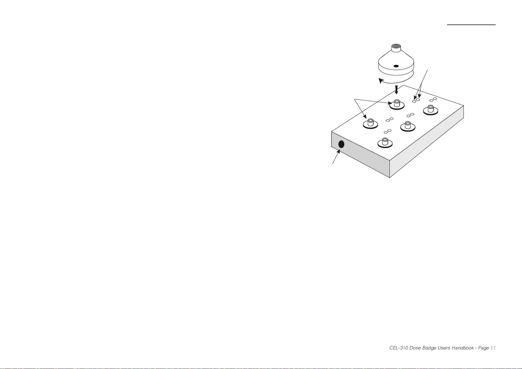
Preparation
Carefully screw
the Dose Badge
on to the stud
Charging studs
Power socket
Figure 4: Fitting a Dose Badge on to a Charger
1. Make sure the Dose Badge is in Stop Mode.
2. Carefully screw it on to the charging stud of a CEL-6807 Charger.
The five badge CEL-6807/5 charger is shown in Figure 4.
3. Connect the Charger unit to the mains supply and switch the
power ON.
Charging indicators
03004
When the charging process begins, the battery will first be fully
discharged to ensure that it does not develop a “memory”.
During this period, which may take up to 2 hours, the green
charge indicator should give “short” flashes (i.e. off more than
lit).
Once the battery has been discharged, the green charge indicator
will give “long” flashes (i.e. lit more than off) to indicate that the
battery is receiving a charge. Charging may take up to 12 hours.
When charging is finished, the green indicator will remain on
continuously to show that the Dose Badge is receiving a trickle
charge to keep it topped up.
CEL-310 Dose Badge Users Handbook - Page 11
Preparation
4. To ensure optimum operation, leave the Dose Badge on trickle
charge when not in use.
2.4 Insert Batteries into the Reader Unit
The Reader Unit requires two AA type batteries for operation. These are
located under the plastic cover on the back of the instrument.
1. Before changing the main batteries, make sure the Reader is OFF.
The memory and clock in the Reader are protected for up to
10 minutes when the main batteries are removed (and it is OFF).
2. Locate the battery compartment cover and remove it from the
instrument.
3. Remove the two batteries from the compartment and replace
them with two batteries of equivalent type and quality.
The recommended battery should be alkaline type AA (LR6 /
AM3 / MN1500 / Mignon).
4. Make sure that the polarity of the batteries is correct, as indicated
by the diagram in the compartment.
5. Replace the battery cover.
2.5 Switch the Reader Unit ON & Check
Configuration
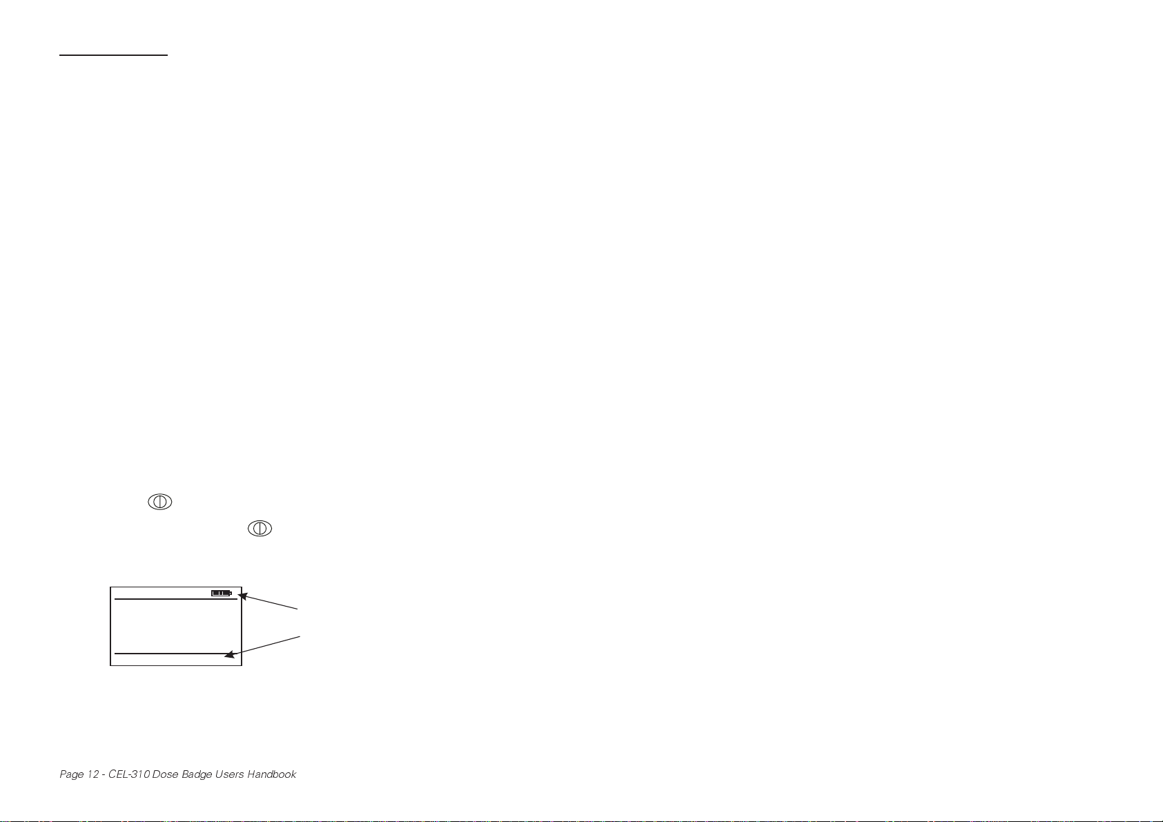
1. Press on the Reader to switch it ON.
(To switch OFF, press again.)
It will display a start screen that is followed by a screen showing
Reader status information.
001 of 010
Serial No.
Meas. time
Meas. Date
Run Time
17:05:28 20/06/02
NNNNNN
16:55
06/02/02
07:45:12
M-01
The Reader will automatically switch itself OFF after four minutes
of inactivity.
Page 12 - CEL-310 Dose Badge Users Handbook
Battery condition
Current time and date
shown in message line

Preparation
The display backlight will be lit when any key is pressed and will
automatically switch off after 10 seconds to preserve battery
power.
2. If the display contrast is not satisfactory, press to display the
Main Menu.
The menu structure for the Reader is shown on a fold out sheet
at the back of this handbook.
Reader Main Menu
Clear Memory
Set Clock
Print Current Data
Print All Data
10 Measurements
M-02
Options
Message line
Active key option
The Main Menu offers a series of options that scroll up or down
the screen when the reverse video cursor is moved.
3. Use or to move the cursor and select Adjust LCD
Contrast.
4. Press to display the Adjust LCD Contrast Menu.
OK
Two options are offered: Lighten or Darken.
Menu
5. Move the cursor to select the required option.
6. Press again to save the setting and return to the Main Menu.
(Alternatively, press to save the setting and return to the
Menu
OK
status screen.)
7. To check the configuration, press to display the Main Menu.
Menu
8. Check the clock setting by using to move the cursor and
select Set Clock.
The time and date are indicated in the message line at the bottom
of the display.
9. Check the time history (profile) status by using to select
Time History Control.
The current setting is indicated in the message line.
CEL-310 Dose Badge Users Handbook - Page 13

Preparation
10. Check the setting for criterion time (i.e. duration of a nominal
working day) by using to select Criterion Time.
The criterion time is indicated in the message line.
11. Check the setting for criterion level (i.e. level to give 100% dose
in a “normalised” 8 hour day) by using to select Criterion
Level.
The criterion level is indicated in the message line.
12. Check the dose badge settings by using to select Dose
Badge Settings.
The current settings are indicated in the message line.
13. When all of the settings are correct for the proposed job, proceed
directly to Chapter 4: Operation.
However, if any of the settings checked in this section are
incorrect, change them according to Chapter 3: Configuration.
Page 14 - CEL-310 Dose Badge Users Handbook
 Loading...