

Casella CEL CEL-281 User Manual

CEL-281
COMPUTING NOISE
DOSIMETER
Operator's Handbook
for
archive Document
Discontinued Instrument
Document 060112
Issue: 4B
March 1996
Supplementary Information - July 1996
Revised Microphone Arrangements
Since this handbook was prepared, a redesigned microphone arrangement has come into use.
1. The current instrument features a redesigned microphone
arrangement with a 1/4" diameter microphone housing replacing the microphone in a 9 mm (3/8") housing described in this
handbook which was used on earlier instruments.
In consequence, the CEL-4725 1/4" Microphone Coupler
required during acoustic calibration (and supplied with CEL-282
and CEL-284/2 Calibrators) should now be used. The CEL-6050
Microphone Coupler used with the earlier microphones is no
longer included.
2. Due to other minor changes in the microphone assembly, the
calibration level for all CEL 1/4" microphones has been changed
to 113.6 dB from the 114.0 dB previously quoted.
When an instrument has 1/4" microphone, or a replacement 1/4"
microphone supplied after 1-1-96,
USE THE 113.6 dB CALIBRATION LEVEL.
Page ii - CEL-281 Operator's Handbook
Contents Overview
Getting Started ..........Chapter 1
Using the dosimeter for routine measurement.
Introduction to The CEL-281 ....Chapter 2
Introduction to the instrument and explanation of terms used
How it Works ...........Chapter 3
Detailed description of the instrument and how it is controlled
Preparation for Use ........Chapter 4
How to calibrate the instrument and prepare it for use
Obtaining Required Results ....Chapter 5
How to use the keypad to obtain results
Printing Hard Copy Reports ....Chapter 6
How to download finished reports to a printer.
Technical Information .......Chapter 7
Includes schedule of parts, instructions for replacing the
microphone and technical specification
Warranty & Service ........Chapter 8
Index
CEL-281 Operator's Handbook - Page iii
Contents ................ Page
1 GETTING STARTED . . . . . . . . . . . . . . . . . . . . . . . . . 1
1.1 Check Batteries . . . . . . . . . . . . . . . . . . . . . . . 1
1.2 Load Batteries . . . . . . . . . . . . . . . . . . . . . . . . 2
1.3 Start-up . . . . . . . . . . . . . . . . . . . . . . . . . . . 3
1.3.1 Quick Start . . . . . . . . . . . . . . . . . . . . . . . . . 3
1.3.2 Acoustic Calibration . . . . . . . . . . . . . . . . . . . . . 4
1.3.3 Set Time Weighting . . . . . . . . . . . . . . . . . . . . . 6
1.3.4 Set Frequency Weighting . . . . . . . . . . . . . . . . . . 6
1.4 Start & Stop Logging Manually . . . . . . . . . . . . . . . 6
1.5 Read Leq&L
1.6 Read Pa2h..........................8
1.7 Read %Dose & P%Dose . . . . . . . . . . . . . . . . . . 9
1.8 Retrieve Peak Exceedance Times . . . . . . . . . . . . 10
2 INTRODUCTION TO THE CEL-281 . . . . . . . . . . . . . . . . 13
2.1 Introduction . . . . . . . . . . . . . . . . . . . . . . . . 13
2.2 Explanation of Terms Used . . . . . . . . . . . . . . . . 16
2.2.1 Sound Exposure . . . . . . . . . . . . . . . . . . . . . . 16
2.2.2 Criterion Level . . . . . . . . . . . . . . . . . . . . . . . 18
2.2.3 Threshold .........................19
2,2.4 Exchange Rate "Q" . . . . . . . . . . . . . . . . . . . . 19
2.2.5 Noise Dose . . . . . . . . . . . . . . . . . . . . . . . . 21
2.2.6 Distribution . . . . . . . . . . . . . . . . . . . . . . . . 22
2.2.7 Probability % . . . . . . . . . . . . . . . . . . . . . . . 23
2.2.8 Cumulative % . . . . . . . . . . . . . . . . . . . . . . . 23
2.2.9 Profiles . . . . . . . . . . . . . . . . . . . . . . . . . . 25
......................7
MAX
3 HOW IT WORKS . . . . . . . . . . . . . . . . . . . . . . . . . 27
3.1 Principle of Operation . . . . . . . . . . . . . . . . . . . 27
3.1.1 Control and Calibration . . . . . . . . . . . . . . . . . . 27
3.1.2 Level ...........................29
3.1.3 Time Information . . . . . . . . . . . . . . . . . . . . . 29
3.1.4 Distribution . . . . . . . . . . . . . . . . . . . . . . . . 29
3.1.5 Profile . . . . . . . . . . . . . . . . . . . . . . . . . . . 30
3.1.6 Dose............................30
3.2 Technical Description . . . . . . . . . . . . . . . . . . . 30
3.2.1 Analog Section . . . . . . . . . . . . . . . . . . . . . . 30
3.2.2 Digital Section . . . . . . . . . . . . . . . . . . . . . . . 32
Page iv - CEL-281 Operator's Handbook
Contents (continued) ......... Page
3.3 Control Facilities: CEL-6012 Keypad . . . . . . . . . . . 36
3.3.1 Display/Power Key . . . . . . . . . . . . . . . . . . . . 38
3.3.2 DoseKey......................... 39
3.3.3 Stop/Battery/Calibration Key . . . . . . . . . . . . . . . 40
3.3.4 Run/Pause Key . . . . . . . . . . . . . . . . . . . . . . 42
3.3.5 NoiseLevelKey ..................... 43
3.3.6 Frequency Weighting Key . . . . . . . . . . . . . . . . 45
3.3.7 Distribution Key . . . . . . . . . . . . . . . . . . . . . . 45
3.3.8 Profile Key . . . . . . . . . . . . . . . . . . . . . . . . 48
3.3.9 Clock Key . . . . . . . . . . . . . . . . . . . . . . . . . 50
3.3.10 "Q"Key .......................... 55
3.3.11 Criterion Key . . . . . . . . . . . . . . . . . . . . . . . 56
3.3.12 ThresholdKey ...................... 56
3.4 Memory Functions . . . . . . . . . . . . . . . . . . . . 57
3.5 Interface . . . . . . . . . . . . . . . . . . . . . . . . . 58
3.6 Power Supply . . . . . . . . . . . . . . . . . . . . . . . 60
4 PREPARATION FOR USE . . . . . . . . . . . . . . . . . . . . . 61
4.1 Switching Instrument Power ON/OFF . . . . . . . . . . 62
4.2 Installing and Removing the CEL-6012 Keypad . . . . . 63
4.3 Loading Batteries . . . . . . . . . . . . . . . . . . . . . 64
4.4 Checking Batteries . . . . . . . . . . . . . . . . . . . . 65
4.5 Performing a Field Accuracy Check (Acoustic Calibration) 66
4.6 Setting Clock Functions . . . . . . . . . . . . . . . . . 71
4.6.1 Setting Current Time and Date . . . . . . . . . . . . . . 71
4.6.2 Setting Delay Times and Dates . . . . . . . . . . . . . . 74
4.7 Making Preliminary Settings . . . . . . . . . . . . . . . 78
4.7.1 Setting Time Weighting . . . . . . . . . . . . . . . . . 78
4.7.2 Setting Frequency Weighting . . . . . . . . . . . . . . 80
4.8 Starting And Stopping Data Logging . . . . . . . . . . . 82
4.8.1 Start Data Logging . . . . . . . . . . . . . . . . . . . . 82
4.8.2 Pause Data Logging . . . . . . . . . . . . . . . . . . . 84
4.8.3 Stop Data Logging . . . . . . . . . . . . . . . . . . . . 84
4.9 Wearing the Dosimeter . . . . . . . . . . . . . . . . . . 85
5 OBTAINING REQUIRED RESULTS . . . . . . . . . . . . . . . . 87
5.1 SoundLevelMeter.................... 87
5.2 Noise Dose . . . . . . . . . . . . . . . . . . . . . . . . 90
5.3 Time Information . . . . . . . . . . . . . . . . . . . . . 93
CEL-281 Operator's Handbook - Page v
Contents (continued) .......... Page
5.4 Distribution . . . . . . . . . . . . . . . . . . . . . . . . 96
5.5 Profiles . . . . . . . . . . . . . . . . . . . . . . . . . . 98
5.6 Example Operations . . . . . . . . . . . . . . . . . . 101
5.6.1 Measuring L
5.6.2 Measuring Pa
5.6.3 Measuring %Dose and P%Dose . . . . . . . . . . . . 104
5.6.4 Finding Amount of Time Spent Above a Specified Level 106
5.6.5 Retrieving Peak Exceedance Times . . . . . . . . . . 107
6 PRINTING HARD COPY REPORTS . . . . . . . . . . . . . . . 109
6.1 Selecting a Printout Format . . . . . . . . . . . . . . . 109
6.2 Setting the Printer . . . . . . . . . . . . . . . . . . . . 110
6.3 Performing a Printer Download . . . . . . . . . . . . . 111
7 TECHNICAL INFORMATION . . . . . . . . . . . . . . . . . . 115
7.1 Schedule of Parts . . . . . . . . . . . . . . . . . . . . 115
7.2 Replacing The Microphone . . . . . . . . . . . . . . . 116
7.3 Specification . . . . . . . . . . . . . . . . . . . . . . 121
8 MANUFACTURERS SERVICING &
WARRANTY ARRANGEMENTS . . . . . . . . . . . . . . . . . 127
INDEX . . . . . . . . . . . . . . . . . . . . . . . . . . . . . 131
and L
eq
2
h..................... 103
................ 101
MAX
Page vi - CEL-281 Operator's Handbook

CEL-281 Operator's Handbook - Page vii
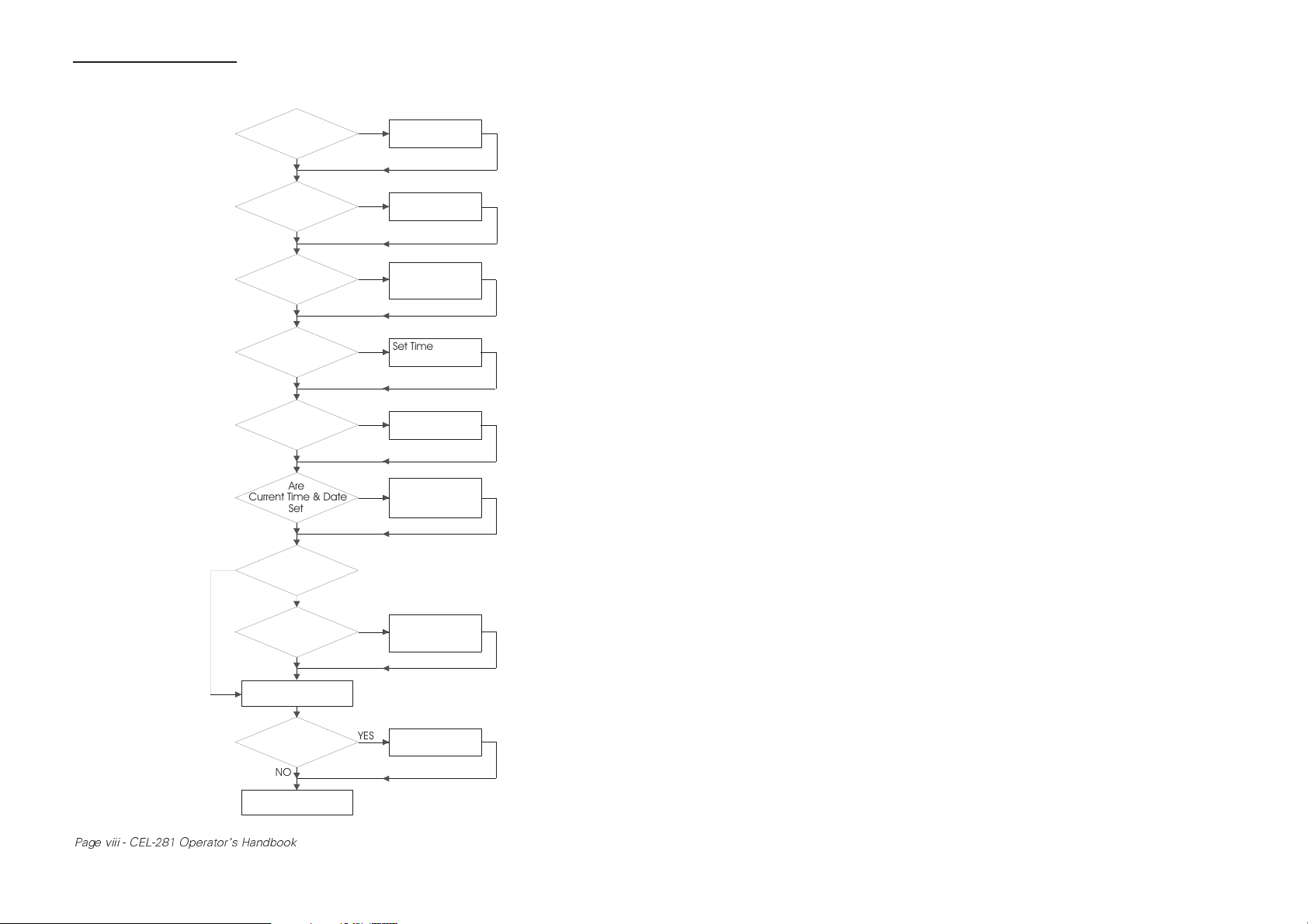
Getting Started_
*Acoustic Calibration
Is Recommended
Before Each
Operational Run
NO
Are There
Batteries In The
CEL-281
YES
Is
Battery Voltage
OK
YES
Do You
Want To Per for m
Calibration*
NO
Is Current
Time Weighting
OK
YES
Is Current
Frequency Weighting
OK
YES
Are
Current Time & Date
Set
YES
Do You
Need Delayed Start &
Stop Times
YES
Are
Delayed Start & Stop
Times Set
YES
Load Batteries
NO
NO
YES
NO
NO
NO
NO
(Section 6.3)
Replace Batteries
(Section 6.3)
Perform Acoustic
(Section 6.5)
Set Time Weighting
(Section 6.7)
Set Freq. Weighting
(Section 6.7)
Set Current Time
(Section 6.6)
Set Delayed Start &
Stop Times & Dates
Calibration
& Date
(Section 6.6)
Press RUN Button
Do You
Need The Display
NO
920094
LOGGING DATA
Page viii - CEL-281 Operator's Handbook
OFF
YES
Switch Display
OFF

Getting Started
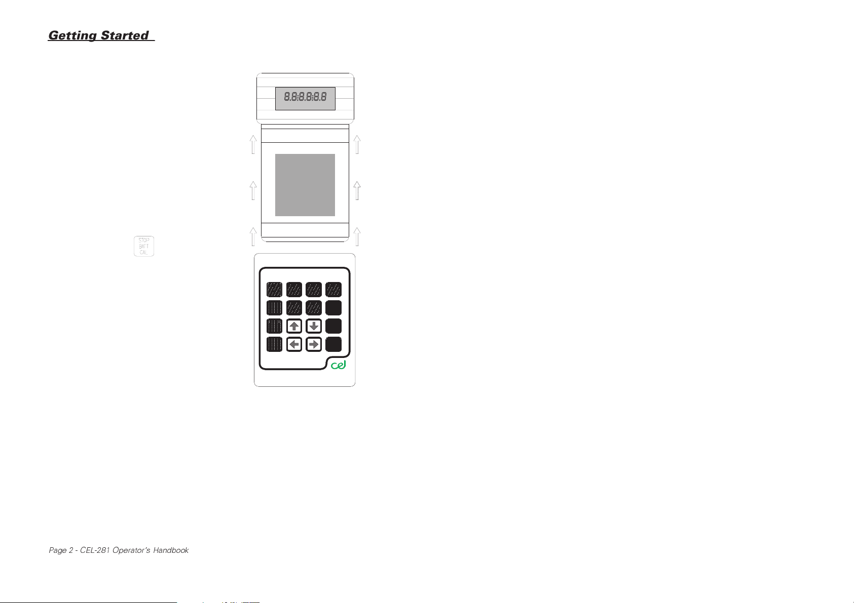
1 GETTING STARTED
It is not necessary to re-program the
CEL-281 each time it is used !
In fact, if the settings for frequency weighting and time weighting stored
from the previous operation are suitable for current measurements, it
may NEVER need programming.
Unlike most other logging dosimeters, with the CEL-281 Computing
Noise Dosimeter there is no need to specify which parameters to save
before data is stored.
It stores ALL parameters simultaneously, so any decision to examine a
particular parameter is left until the read-out stage, while the keypad is
used mainly to extract stored data in the field, or when no PC loaded
with the CEL-6171 Application Software is available.
On the CEL-281, there are normally only THREE items that MAY EVER
need attention: indicated calibration level, time weighting, and frequency
weighting.
Once set, these could well be suitable for a whole series of measurements, so that NO FURTHER SETTING is necessary when the instrument is next used.
1.1 Check Batteries
1. Use the 1.5 mm Allen Key supplied to retract the locking screw
and free the lower sliding cover.
2. Switch the instrument ON.
3. Install the keypad.
The plug and socket of the 15-line connectors will align correctly
and engage automatically.
CEL-281 Operator's Handbook - Page 1
Getting Started_
If the display blinks,
remains blank, or LOW
BAT is indicated: either
there is insufficient
power or the batteries
are inserted incorrectly
(see Section 1.2 Load
Batteries).
4. Wait 20 s for the instrument to become fully
operational.
5. Press the key to
display the battery voltage.
6. Replace batteries when
the voltage falls near
4.2 V to ensure operation for a full 8 hour
shift.
920066
1.2 Load Batteries
Zinc carbon or rechargeable nickel cadmium types are NOT SUITABLE
as they have insufficient operating life to last for a standard 8 hour working shift..
1. Use the 1.5 mm Allen Key to retract the lockings crew and free
the lower sliding cover.
2. Switch the instrument OFF.
3. Use the Allen Key to retract the locking screw and free the
battery compartment cover.
Page 2 - CEL-281 Operator's Handbook
920067
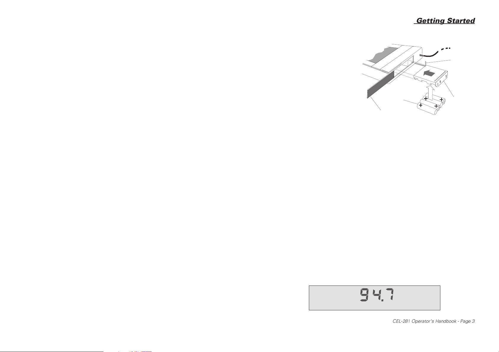
Getting Started
4. Load four AAA or
920064
LR03 batteries
into the holder
Allen Key
supplied, according to polarities
shown on the
bottom of the
holder, then insert it into the
battery compartment.
Batteries
Cover
Holder
5. Replace and lock the battery compartment cover then install
the keypad.
1.3 Start-up
If the battery voltage is satisfactory, choose between calibrating the unit
(see Calibration), or operating with the previous calibration setting (see
Quick Start).
1.3.1 Quick Start
1. Use the 1.5 mm Allen Key to retract the locking screw and free
the lower sliding cover.
2. Switch the instrument ON.
CAL is displayed and blinks for 20 s.
3. Wait until the display shows a level such as:
ON
LAVG
TC=f Q=3
CEL-281 Operator's Handbook - Page 3
dBA
920063

Getting Started_
4. If an incorrect time weighting for the required measurements is
indicated at "TC=?", go to Section 1.3.3: Set Time Weighting.
5. If an incorrect frequency weighting for the required measurements is indicated at "dB?", go to Section 1.3.4: Set Frequency
Weighting.
6. When the indicated time and frequency weightings are satis-
factory, press the key.
The CEL-281 starts to collect data at the next whole clock
minute.
1.3.2 Acoustic Calibration
Check the acoustic calibration immediately before making measurements with the CEL-281. (Note that calibration AFTER measurement
overwrites the initial calibration level used in any printout via a PC program.
Use a CEL-282 Acoustic Calibrator (Class 2) or a CEL-284/2 Calibrator
(Class 1); both provide a nominal 114.0 dB at 1 kHz.
1. Push the microphone firmly into the cavity of CEL-6050 Coupler
supplied.
2. Push the coupler and microphone firmly into the calibrator cavity.
3. Use the 1.5 mm Allen K ey to retract the locking screw and free
the lower sliding cover.
4. Switch the CEL-281 ON.
CAL is displayed and blinks for 20 s. If calibration is not initiated
within this period, the CEL- 281 becomes fully operational using the settings stored from last time of operation.
Page 4 - CEL-281 Operator's Handbook
"O" Rings
Getting Started
Microphone
920065
CouplerCalibrator
5. Install the keypad.
If the 20 s delay has elapsed before the cover and keypad have
been installed, CAL stops blinking and the instrument becomes
fully operational.
6. During the 20 s calibration delay, or when fully operational (with
no data being logged), press the + keys simultaneously to enter calibration mode, which is indicated by "C" ahead
of the displayed level.
The instrument displays SPL in dB(A) with Fast time weighting.
7. Switch the calibrator ON.
When used with the CEL-281 and CEL-6050 Coupler at standard
temperature and pressure, the calibrator generates a 1 kHz
signal at 114.0 dB, so the display should show "C 114.0 dBA".
8. If the display does not indicate 114.0 dBA, use the or
keys to obtain the correct level.
Acoustic calibration is now complete.
CEL-281 Operator's Handbook - Page 5
Getting Started_
Warning
To prevent damage, DO NOT EXERT FORCE on
the flexible crosspiece when removing the
microphone from the calibrator coupler.
PULL ONLY on the rigid microphone casing.
9. Switch the calibrator OFF, then remove it together with the
coupler.
10. Press the key once to leave calibration mode.
1.3.3 Set Time Weighting
1. Immediately after calibration, press the or keys
to change the time weighting to the required value: (data),
(fast), (slow) or (impulse).
1.3.4 Set Frequency Weighting
1. While the CEL-281 is operating but not collecting data, press
the key to obtain the required frequency weighting.
1.4 Start & Stop Logging Manually
Refer to Section 6.6 - 6.8 for start and stop times controlled by the clock.
If logging has been stopped using the + key combination, all
stored data will be lost next time logging is started.
With the CEL-281 switched ON, the keypad installed:
Page 6 - CEL-281 Operator's Handbook

Getting Started
1. Press the key to start data logging.
The instrument starts to store data samples at the beginning of
the next whole clock minute.
2. Press the key to pause logging if further data is to be
added to file later.
3. Press the + combination to stop logging when
no further data is to be added.
4. Connect the dosimeter to a PC equipped with the CEL-6171
Application Software for data download so that all data can be
viewed, or to printer to obtain a hard copy of a data "Subset".
1.5 Read Leq&L
With the CEL-281 switched ON, the keypad installed:
1. Press the key to obtain the "dBA" legend (if not shown).
2. Press the key once to display dB readings.
3. If the "dBA" legend is no longer shown, press the key
again to obtain it.
The dosimeter is now operating as a sound level meter, indicating instantaneous sound pressure levels (SPL) in dB(A) on
the main display, with the current time constant "TC=?" indicated just below.
MAX
CEL-281 Operator's Handbook - Page 7
Getting Started_
4. Press the key once.
5. If some other value than 3 is shown at "Q=?", press the
key enough times to obtain "Q=3".
The main display now indicates Leq, (A-weighted L
Q=3) and if the instrument contains stored data or is logging
data, a level will be given.
6. Press the key a second time.
The main display now shows A-weighted Slow Max.
7. Press the key a third time.
The main display now shows A-weighted Slow SPL.
8. Press the key a fourth time.
The main display now shows A-weighted Fast Max.
1.6 Read Pa2h
With the CEL-281 switched ON, the keypad installed:
AVG
with
1. Press the key once.
2
2. If Pa
Page 8 - CEL-281 Operator's Handbook
h is not shown to the right of the main display, press the
key again to obtain it.

Getting Started
The main display now indicates sound exposure level in Pa2h,
and if the instrument contains stored data or is logging data, a
level will be given.
1.7 Read %Dose & P%Dose
With the CEL-281 switched ON, the keypad installed:
1. Press the key once.
2. If the required parameter is not shown, press the key
again to show it.
The main display now indicates %Dose or P%Dose with the
exchange rate shown at "Q=?", and whatever Criterion and
Threshold Levels are set. When the instrument contains stored
data or is logging data, a level will be given.
3. If necessary, change the exchange rate by slowly pressing the
key sufficient times to obtain the desired rate.
The re-calculated dose value is displayed immediately.
4. If necessary, view the current criterion level (at "Cri") by press-
ing the key once.
5. If necessary, press the key slowly sufficient times to
show the required criterion on the main display. Then press the
key again to display dose calculated using the new crite-
rion level.
CEL-281 Operator's Handbook - Page 9

Getting Started_
6. If necessary, view the current threshold level (at "Thr") by press-
ing the key once.
7. If necessary, press the key slowly sufficient times to
show the required threshold on the main display. Then press
the key again to display dose calculated using the new
threshold level.
1.8 Retrieve Peak Exceedance Times
With the CEL-281 switched ON, the keypad installed:
1. Press the key once.
The main display indicates current time.
2. If necessary, press the key again to check the date.
3. Press the + key combination once.
The main display indicates the first time or date when the
200 Pa level was exceeded. If the displays shows __:__:__ ,no
exceedance has occurred.
4. If time is indicated, press the key once to see the date.
5. If date is indicated, press the key once to see the time.
Page 10 - CEL-281 Operator's Handbook
Getting Started
6. Press the key once.
The main display indicates the last time or date when the
200 Pa level was exceeded.
7. If time is indicated, press the key once to see the date.
8. If date is indicated, press the key once to see the time.
CEL-281 Operator's Handbook - Page 11

Getting Started_
Page 12 - CEL-281 Operator's Handbook

_Introduction
2 INTRODUCTION TO THE CEL-281
2.1 Introduction
The CEL-281 Computing Noise Dosimeter stores all of its parameters simultaneously, so the operator may need to specify only frequency
weighting before data can be saved. Any decision about which parameters to examine is left until the read-out stage. The majority of keys on
the keypad are used only to extract data in the field, or when no PC
equipped with CEL-6171 Dosimeter Application Software is available.
The CEL-281 is a comprehensively specified logging instrument that calculates and stores a broad range of noise dose and noise level information, to quote a well known news-paper:
"You don't have to read it all, but it's nice to
know it's all there."
Where other dosimeters simply identify the presence of a noise hazzard,
the CEL-281 stores a complete noise history as shown on the following
page. This enables the operator first to identify a problem, then to zoom
in with fine resolution to evaluate and locate the cause. Designed for use
by acoustic engineers and consultants, it provides the means to make
complex assessments of an individual's exposure in the field as well as
the ability to download data for further analysis.
The computing noise dosimeter is manufactured to meet rigorous standards that include BS 6402, ANSI S1.25 1978 Type 2, ANSI S1.4 1983,
and IEC 804 Type 2. It makes measurements according to ISO 1999:
1990 "Determination of Occupational Noise Exposure and Estimation of
Noise Induced Hearing Impairment" and the U.K. "Safety and Health at
Work Act: Noise at Work Regulations 1989".
It can also be used to monitor hearing conservation programs and make
the measurements required by the U.S.A. Occupational Safety and
CEL-281 Operator's Handbook - Page 13
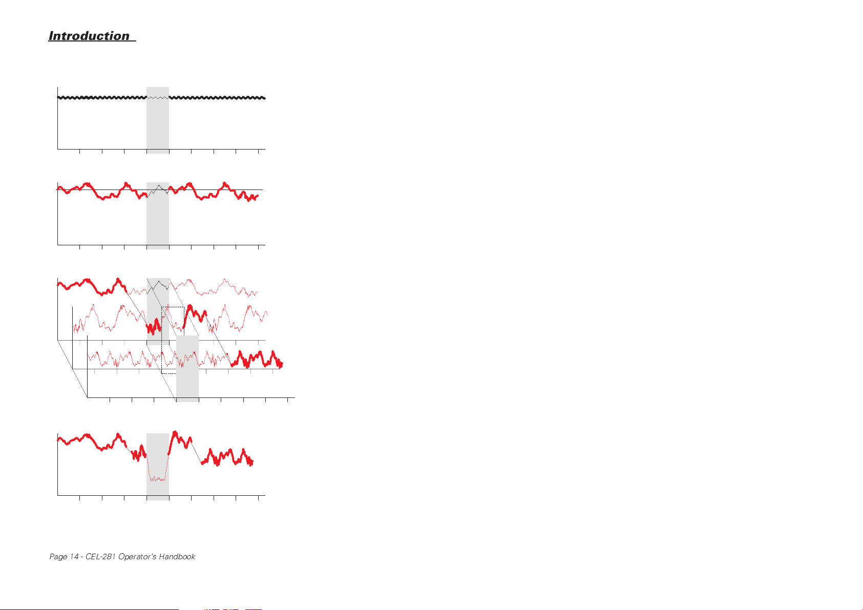
Introduction_
Level
Level
Level
Meal
Break
Meal
Break
Time (hours)
L
eq
Time (hours)
Machine noise at
constant level is easily
measured with simple
SLM like CEL-231 or
CEL-254
Machine noise with large
variations in level is best
measured by integrating
SLM like CEL-269
When worker spends
periods on several
different machines use
dosimeter like CEL-272
to measure noise dose
Level
Meal
Break
Time (hours)
When worker spends
periods on several
different machines use
logging dosimeter
CEL-281 to store
complete record for
later evaluation of
noise problems
900161
Meal
Break
Time (hours)
The application of different types of sound measurement instrument
Page 14 - CEL-281 Operator's Handbook

_Introduction
Health Authority regulations OSHA 1910.95 "Occupational Noise Exposure".
The CEL-281 is intended to be worn by an individual so that its microphone is subjected to as nearly as possible the same sound exposure as
the wearer (or as otherwise recommended by relevant local legislation).
When necessary, an operator can set the time and frequency weightings
to be used in the measurements, and pre-program start and stop times
and dates for data logging by means of a detachable CEL-6012 Keypad.
This slides on to the dosimeter casing, making contact via a 15-line connector.
Once the operator has made the preliminary settings, it should be possible for a long series of similar measurements to be made without further
changes. The 16 pressure sensitive keys in the keypad allow a wide
range of parameters and measurements to be selected. These include:
• Choice of A- or C-frequency weightings,
• Choice of Fast, Slow or Impulse time weightings,
• Choice of 10 measurement start and 10 measurement
stop times,
• Measurement of noise levels in decibels (dB) and Pascal-
squared hour (Pa
• Measurement of average and equivalent (L
with various exchange rates (Q), threshold levels, and
criterion values,
• Measurement of noise dose in %dose and projected %dose
units with various exchange rates (Q), threshold levels, and criterion values,
• Determination of noise level and equivalent noise level (L
tribution in terms of cumulative% and probability% with
various sampling periods,
• Measurement of noise, maximum noise, and equivalent noise
(L
) history profiles with various exchange rates (Q) and sam-
AVG
pling periods.
2
h) energy units,
) noise levels
eq
eq
) dis-
CEL-281 Operator's Handbook - Page 15

Introduction_
The keypad can be removed to eliminate the danger of accidentally resetting the instrument or losing measurements. This will also prevent
unauthorised tampering with and damage to the keypad, ensuring a long
and effective life for the instrument.
The dosimeter module carried by the wearer is housed in a strong abrasion resistant plastic case, with the connector protected by a sliding
cover and the microphone attached via a screened lead. The casing is devoid of all switches and features only a large digital display which shows
measurement criteria and results simultaneously. If added security is required, the display can be switched off when required.
After noise measurements have been completed, the CEL-281 can be
connected via the keypad connector, directly to a PC for further analysis,
data manipulation, origination of report ready documentation, and permanent storage of an individual's noise exposure pattern. For example,
noise dose data can be exported into a suitable file structure to enable
manipulation in industry standard database and spreadsheet formats and
allow linking with existing personnel records.
It is also possible to download a preselected selection from the contents
of the dosimeter store directly to a standard printer via a standard CEL
C6231 Interface Cable.
This handbook describes operation of the CEL-281 Dosimeter with the
CEL-6012 Keypad and printer only.
Operation with a PC is described in the CEL-6171 Application Software
handbook.
2.2 Explanation of Terms Used
2.2.1 Sound Exposure
Sound Exposure is often thought of in terms of Noise Dose be-
cause it is similar in concept to the Dose-Exposure relationship used
in occupational medicine when defining the maximum permissible human exposure limits to toxic substances.
Page 16 - CEL-281 Operator's Handbook
_Introduction
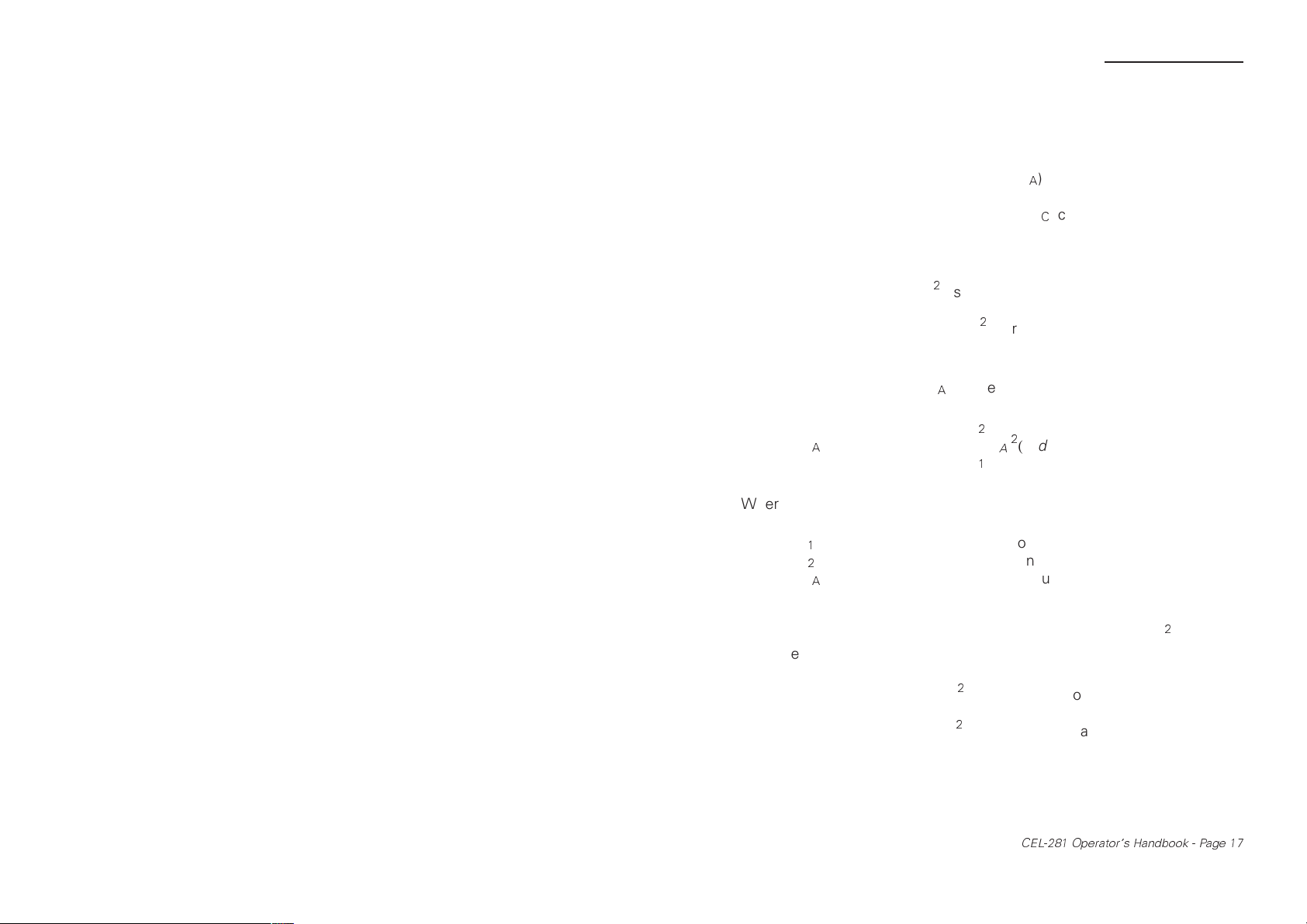
Both terms are in common use, but the most recent international standards specify sound exposure.
The value of sound exposure measured (E
) is normally defined as the
A
product of exposure time and the amount of A-weighted energy contained in the sound. A similar relationship (E
) can be defined for expo-
C
sure to C-weighted sound energy.
Sound Energy is proportional to the square of sound pressure and has
the units Pascal-squared (Pa
come Pascal-squared seconds (as stipulated by the ISO Standard). However, Pascal-squared hours (Pa
2
), so that the units of sound exposure be-
2
h) are normally used in order to
obtain more manageable numbers (IEC Standard).
Therefore Sound Exposure E
E
A
can be defined as follows:
A
t
2
=
2
P
(t).dt
A
∫
t
1
Where:
t
1
t
2
P
A
= Integration start time (hours),
= Integration end time (hours),
= Instantaneous A-weighted sound
pressure (Pa).
In the CEL-281, sound exposure is calculated and stored in Pa
2
h, while
sound levels are expressed in dB.
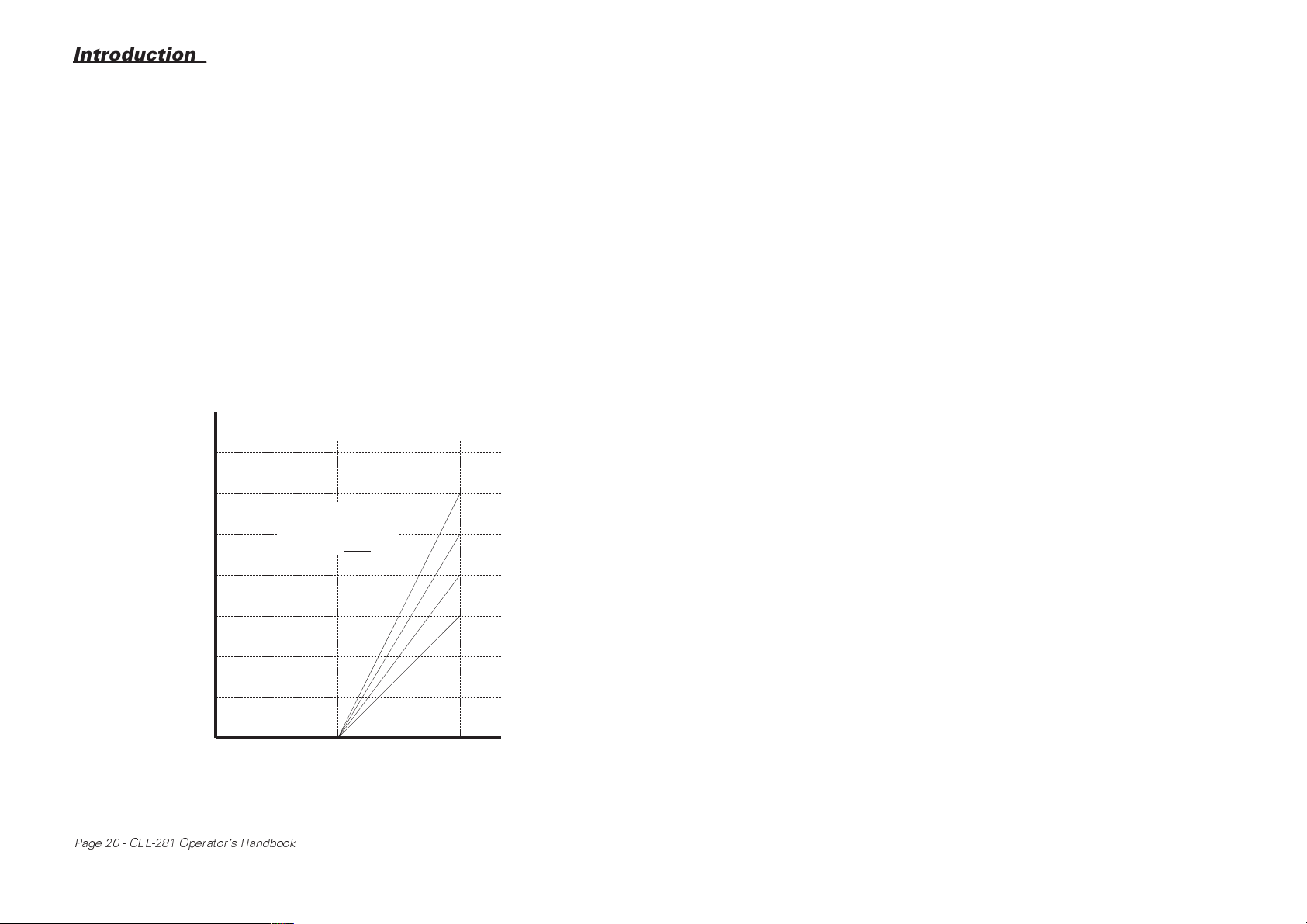
A sound exposure value of 1 Pa
level of approximately 85 dB(A) for eight hours (see Figure 1), while a
sound exposure value of 3.2 Pa
2
h is equivalent to a continuous sound
2
h is exactly equivalent to a continuous
sound level of 90 dB(A) for eight hours.
Recent European noise exposure legislation mentions three action levels
(which are also shown in Figure 1).
CEL-281 Operator's Handbook - Page 17
Introduction_
2nd Action
Level 3.2
E
A
L
EP,d
D
900045
2
Pa h
dB(A)
%Dose
1st Action
Level 1.0
0.3 0.4 0.5 0.6 0.8 1.0 2.0 3.0 4.0 5.0 6.0 8.0 10 20 30 40 50 60 80 100
80 82 84 86 88 90 92 94 96 98 100 102 104 106
10 20 30 40 50 60 80 100 200 300 400
Figure 1: Relationship between EA, D, and L
Peak Action Level 200 Pa
Triggers Overload Indication
600 800
1000
for a normalised
EP,d
2000 30004000
eight hour working day with 90 dB equivalent to 100% dose
At levels below the First Action Level (1.0 Pa2h - equivalent to 85 dB(A)
for 8 hours) "reasonably practicable" noise reductions should be made.
Between the First and Second Action Levels (3.2 Pa
2
h - 90 dB(A) for 8
hours) noise assessments must be made, records kept, details given to
employees, and hearing protection issued to those who ask for it. Above
the Second and also at or above the Peak Action Level (200 Pa - 140 dB
for any period), hearing protection measures must be enforced by the
employer.
2.2.2 Criterion Level
Many European sound exposure standards specify 90 dB(A) for eight
hours as the Criterion Level used to define 100% Noise Dose.
However, other noise dose legislation may require a different criterion
level for the value of a 100 % noise dose, for example some U.S.A.
Department of Defense (DOD) Standards specify 84 dB, i.e. an exposure of 84 dB for eight hours is equivalent to 100% noise dose.
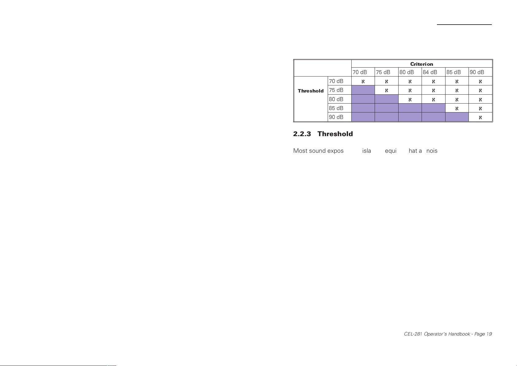
In the CEL-281, results can be calculated and displayed for up to six different criterion levels: 70 dB, 75 dB, 80 dB, 84 dB, 85 dB, and 90 dB.
The instrument will accept the selection only of valid criterion levels, i.e.
levels that are equal to or greater than the Threshold Levels selected.
Refer to Table 1 for valid pairs of levels, and to Section 2.2.3 for an explanation of Threshold Level.
Page 18 - CEL-281 Operator's Handbook
_Introduction
Table 1: Valid pairs of criterion and threshold levels
Criterion
70 dB 75 dB 80 dB 84 dB 85 dB 90 dB
70 dB
Threshold
75 dB
80 dB
85 dB
90 dB
2.2.3 Threshold
Most sound exposure legislation requires that all noise measured during
the measuring period be included in the calculation of noise dose. However, some legislation specifies that only values that exceed some prescribed threshold be considered, so that sound levels below this value
will not be included in the calculation.
In the CEL-281, results can be calculated and displayed for up to five different threshold levels: 70 dB, 75 dB, 80 dB, 85 dB, and 90 dB. The instrument will accept the selection only of valid threshold levels, i.e.
levels that are equal to or less than the criterion levels selected; refer to
Table 1 for valid pairs of levels.
ℵℵℵℵℵℵ
ℵℵℵℵℵ
ℵℵℵℵ
ℵℵ
ℵ
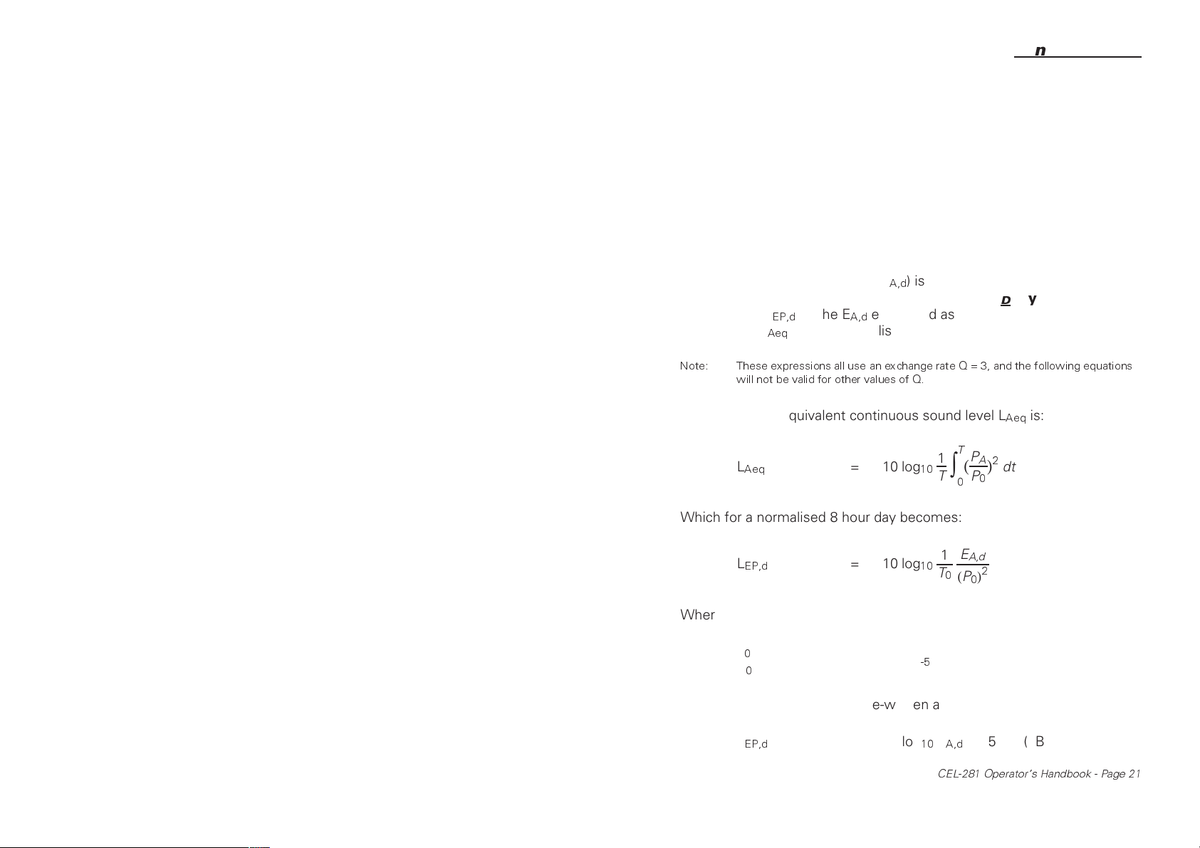
2,2.4 Exchange Rate "Q"
The Equal Energy Exchange Rate is that part of the fundamental
physical relationship which states that when the Energy Content of a
sound is doubled, an increase of 3 dB in the sound exposure level will be
observed. Therefore to maintain an equal noise dose, the exposure time
must be halved
This is the relationship specified by most sound standards, and is equivalent to Q = 3. However, some legislation seeks to define noise dose in
terms of the Estimated Risk Of Hearing Damage.
CEL-281 Operator's Handbook - Page 19
Introduction_
Results obtained by various researchers indicate that when the risk of
hearing damage is being considered, less emphasis need be placed on
the energy contained in higher noise levels.
When necessary, these findings can be incorporated quite simply into
the noise dose calculation by applying a different Exchange Rate, for
example in some of their requirements, the U.S.A. Occupational Health
and Safety Authority (OSHA) specify Q = 5.
Figure 2 illustrates the relationship between the exchange rate Q, hearing damage risk, and the number of dB found to increase the risk.
In the CEL-281, results are calculated and stored for up to four different
exchange rates, Q = 3, 4, 5, and 6.
dB
Change in
Noise Level
found to
increase
Risk of
Hearing Loss
910005
7
6
Q = Slope
5
Q ∝
4
3
2
1
1
Risk
1 x Risk 2 x Risk
Figure 2: Relationship between Q and the risk of hearing loss
Page 20 - CEL-281 Operator's Handbook
Q=6
Q=5
Q=4
Q=3
(Equal Energy)
_Introduction
2.2.5 Noise Dose
Noise dose is not an absolute measurement but a percentage of the recommended maximum daily personal noise exposure.
In this way, 100% noise dose will be equal to the exposure limit for the
person, while values lower than 100% indicate a lesser exposure than
the allowable dose and values above 100% show excessive exposure.
The Daily Sound Exposure (E
sure sustained in a "typical working day", while the
sure Level (L
sound level (L
Note: These expressions all use an exchange rateQ=3,andthefollowing equations
will not be valid for other values of Q.
) is the E
EP,d
) over a normalised working day of eight hours.
Aeq
A,d
The formula for equivalent continuous sound level L
L
Aeq
= 10 log
) is the total A-weighted sound expo-
A,d
aily Sound Expo-
D
expressed as an equivalent continuous
is:
Aeq
T
P
1
A
2
(
)
10
∫
T
0
dt
P
0
Which for a normalised 8 hour day becomes:
E
1
L
EP,d
= 10 log
10
A,d
T
2
0
(P0)
Where:
T
0
P
0
= 8 hours,
= 2x10⁻⁵Pa
Therefore the formula can be re-written as:
L
EP,d
= 10 log10E
CEL-281 Operator's Handbook - Page 21
+ 85 (dB)
A,d
Introduction_
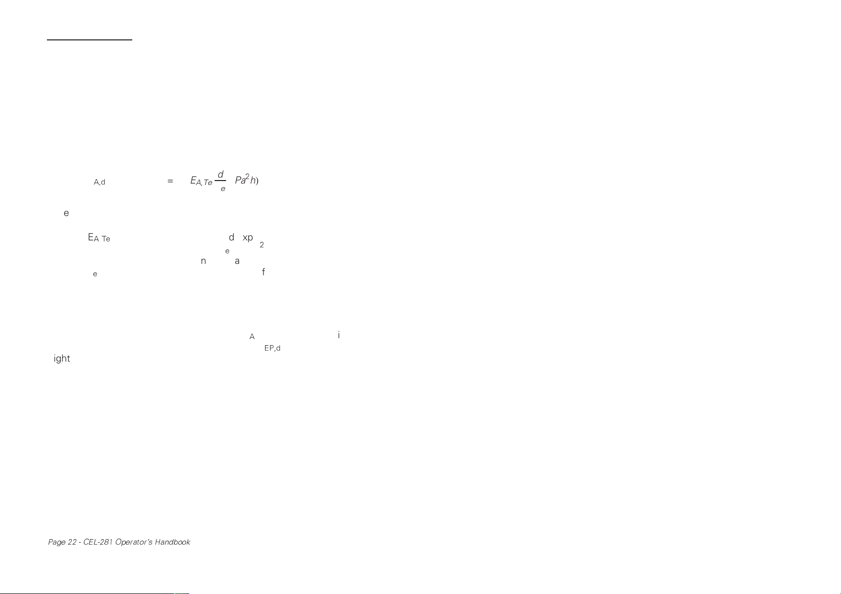
A Projected Sound Exposure can be calculated when a sample exposure has been obtained over a period that is different from the standard eight hour working day.
For example if the exposure determined during a measured part of the
standard day is expected to continue for the remainder of the day, the
sample can be projected for the whole day as follows:
A,Te
d
T
e
(Pa2h)
E
A,d
= E
Where:
E
A,Te
= Measured exposure over sample
period T
in (Pa2h),
e
d = Length of actual working day in hours,
T
e
= Exposure time of sample in hours.
The CEL-281 calculates both % dose and projected % dose values for
an eight hour day only.
The relationships between sound exposure (E
90 dB criterion, and daily sound exposure level (L
), noise dose (D) with
A
) for a normalised
EP,d
eight hour working day are illustrated in Figure 1.
2.2.6 Distribution
This is a statistical determination of how often any particular event occurs during a given survey found by dividing the total range of events recorded in a survey into separate events (or groups of similar events).
Such Statistical Distribution information is presented in the form of
a Histogram showing the number of times the event or group occurred on a Frequency axis plotted against events or groups identified
on the other axis. Frequency is often replaced by Percentage Fre-
quency, which is the proportion of the total survey taken up by the
event.
Page 22 - CEL-281 Operator's Handbook
 Loading...