

Casella CEL CEL-278 User Manual
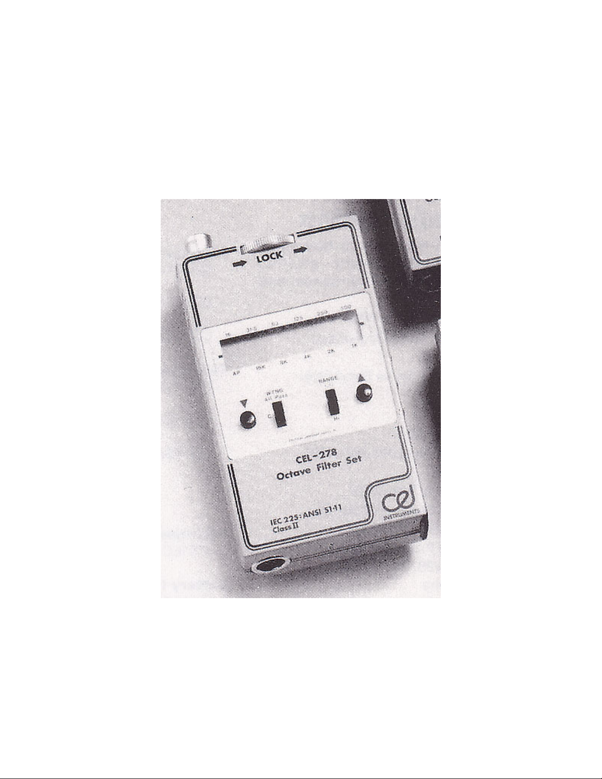
CEL-278/2 OCTAVE FILTER SET
Operator's Handbook
PP60024
Issue: 2
August 1990
CEL Instruments Ltd. CEL-278/2 Handbook Page 1

Page 2 CEL-278/2 Handbook CEL Instruments Ltd

Contents Page
1. Introduction 5
2. Schedule of parts 7
3. Description 9
3.1 Technical description 9
3.2 Display 11
3.3 Control identities 13
3.4 Input facilities 15
3.5 Output facilities 15
3.6 Batteries and auxilliary power supplies 17
4. Preparation for use 19
5. Operation 21
5.1 Preparation for use with other equipment 21
5.2 Manually and remotely scanned analysis 25
6. Specification 27
7. Manufacturers servicing and warranty arrangements 31
8. Calibration certificate 33
CEL Instruments Ltd. CEL-278/2 Handbook Page 3

Page 4 CEL-278/2 Handbook CEL Instruments Ltd

1. INTRODUCTION
The CEL-278/2 Filter Set was designed to meet the requirement for a
portable filter set that allows octave frequency analysis to be performed with
CEL Sound Level Meters.
This requirement has been realised by utilizing a switched capacitor filter,
that can be switched step by step to give the full range of centre
frequencies. The resulting lightweight instrument has 11 octave bands with
centre frequencies from 16Hz to 16kHz. The accuracy of each individual
filter band achieved in this way fulfils the relevant IEC and ANSI Standard
requirements for octave filters.
The Filter Set is primarily intended to operate while directly fitted to the base
of one of the following sound level meters.
CEL-493/2N Precision Integrating Impulse Sound Level Meter
(Type 1I), CEL-275/2A, /2B, /2C, & /2D Precision Integrating
Impulse Sound Level Meters (Type 1I),
CEL-383/2A, /2B, /2C, & /2D Integrating Impulse Sound Level
Meters (Type 2I).
A factory conversion is available to adapt the following older versions of
these sound level meters so that they can be close coupled to the CEL278/2.
CEL-493/2 Precision Integrating Impulse Sound Level
Meter (Type 1I),
CEL-275A & B Precision Integrating Impulse Sound Level
Meters (Type 1I),
CEL-383A & B Integrating Impulse Sound Level Meters
(Type 2I).
CEL Instruments Ltd. CEL-278/2 Handbook Page 5

The CEL-278/2 may be used with other types of CEL instrumentation,
including the following.
CEL-160 Graphic Level Recorder (not "C" version),
CEL-262 Environmental Noise Analyzer (Type 1).
The following other earlier types of CEL sound level meter may also be used,
although special procedures and cables may be required, please consult
your local CEL representative for further details.
CEL-193 Precision Integrating Impulse Sound Level Meter (Type 1I),
CEL-175 Precision Integrating Impulse Sound Level Meter (Type 1I),
CEL-187 Precision Integrating Sound Level Meter (Type 1),
CEL-162 series Environmental Noise Analyzers.
When used with any of these measuring instruments, octave band frequency
analysis of noise and vibration can be performed with manual selection of the
centre frequencies. Alternatively, the combination of Sound Level Meter and
Filter Set may also be connected to an external device such as a CEL-160
Level Recorder or CEL-238A Secondary Processor that can step the octave
bands by remote control while recording the level in each band.
Refer to Chapter 5 for detailed Instructions for operating the Filter Set, and to
Chapter 3 for a technical description of its functions. Please turn to Chapter 4
to prepare the instrument for use.
Page 6 CEL-278/2 Handbook CEL Instruments Ltd

2. SCHEDULE OF PARTS
A complete "CEL-278/2 Octave Filter Set" contains the following items. When
the instrument is delivered, check that all items on the schedule have been
supplied.
CEL-278/2 Octave Filter Set,
IEC LR6 Alkaline battery (4 off),
PP-15018 Pad of filter tables,
PP60024 Handbook.
Special transit packing is provided for the instrument and this should be
retained for use when the instrument is transported or must be consigned by
general carriers. Any instrument returned inadequately packed to the
manufacturer for calibration, service, or repair will be correctly re-packed and
charged accordingly.
The following additional items may be ordered to enable the user to gain full
advantage from the CEL-278/2. They will be itemized separately on the
schedule.
CEL-4697 Set of 4 nicer rechargeable cells,
CEL-4691 Charger Unit required for CEL-4697,
C4531/0.5 Cable Set (0.5m) for automatic frequency analysis with
CEL-160 Graphic Recorder,
C4534/2 Cable (2m) for AC conditioned output and automatic
frequency analysis with CEL-1 60 when Filter Set
mounted on CEL-493/2, CEL-275, or CEL-383 (old or
new) series of sound level meters.
CEL Instruments Ltd. CEL-278/2 Handbook Page 7

Page 8 CEL-278/2 Handbook CEL Instruments Ltd

3. DESCRIPTION
3.1 Technical Description
The CEL-278/2 is designed to be mounted close coupled to the bottom of a
CEL sound level meter. It receives signals to be filtered via line 4 of the
connector in the top of the instrument case, and returns them to the Meter for
measurement via line 6 of the same connector.
Figure 1 Block diagram of the CEL-287/2
CEL Instruments Ltd. CEL-278/2 Handbook Page 9

On "Hi" range the input signal passes directly to the anti-aliasing filter and
thence to the selected octave filter. On "Lo" range, 30dB of gain is added to
raise the signal level well above the noise floor. The input can also be
switched via a C-weighted network, or via the "All Pass" (6Hz to 25kHz) line
directly to the output.
Before the signal is fed to the switched capacitor filter unit for frequency
analysis, it passes through the anti-aliasing filter which removes frequency
components above the band of interest. This prevents the sampling process
from aliasing them into the band for measurement.
The filter unit has a one octave bandwidth, and can be switched to give 11
centre frequencies in one octave steps from 16Hz to 16kHz. Centre
frequency selection is initiated by the
and push buttons, while the
actual band centre frequency is controlled by pulses from the logic unit driven
clock oscillator.
The output from the filter passes through the clock residue filter which further
reduces the spurious components produced during the sampling process. On
"Hi" range, the output from the clock residue filter is fed directly to the Sound
Level Meter for measurement, while on "Lo" range 30dB of attenuation is
introduced first to restore the signal level. This output signal is also available
on line 4 of the bottom connector for transmission to some other measuring
or recording device.
The overall frequency response of the CEL-278/2 filter bands satisfies the
requirements of IEC 225 for octave filters, and of ANSI S1.11-1966 (R1975)
Class II for octave filters (best class), while the C-weighted network meets
Type 1 requirements of the relevant portions of IEC 651, and ANSI 51.4-
1983.
Figure 2 represents a typical response curve for the octave bands, which was
produced using a CEL-193/2 Sound Level Meter to measure the response for
all bands, and then averaging the results.
The range, and bandwidth of the instrument are set manually by controls on
the front panel. When the
or nudge buttons are
Page 10 CEL-278/2 Handbook CEL Instruments Ltd
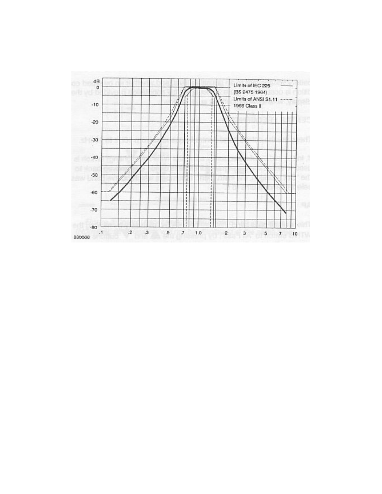
Figure 2 Typical octave filter response curve
pressed, or band step control signals are received via the bottom connector
from an external device such as a level recorder, the logic unit controls the
clock oscillator to step the centre frequency of the filter band. The selected
band centre frequency will be identified by the display.
3.2 Display
As in normal operation the CEL-278/2 Filter Set will be used close coupled to
a CEL sound level meter, the viewing angle of the display has been selected
to give the optimum clarity and legibility when the Instrument is held slightly
away from the Operator's body as required by the relevant measurement
standards, or when fitted to the CEL-4627 Tripod.
Markers on the display adjacent to legends on the bezel identify the filter
centre frequency currently in use. An indication is also given if the
CEL Instruments Ltd. CEL-278/2 Handbook Page 11
 Loading...