

Carrier 69NT40-551-500 PARTS LIST
Container Refrigeration
r
22
1
2
3
4
23 2425 28 30
5
34
2432
SERVICE PARTS LIST
for
69NT40--551--500 to 599
Container Refrigeration Units
T--334PL Rev E Change 11/10

SERVICE PARTS LIST
CONTAINER REFRIGERATION UNIT
MODEL
69NT40-551-500 to 599

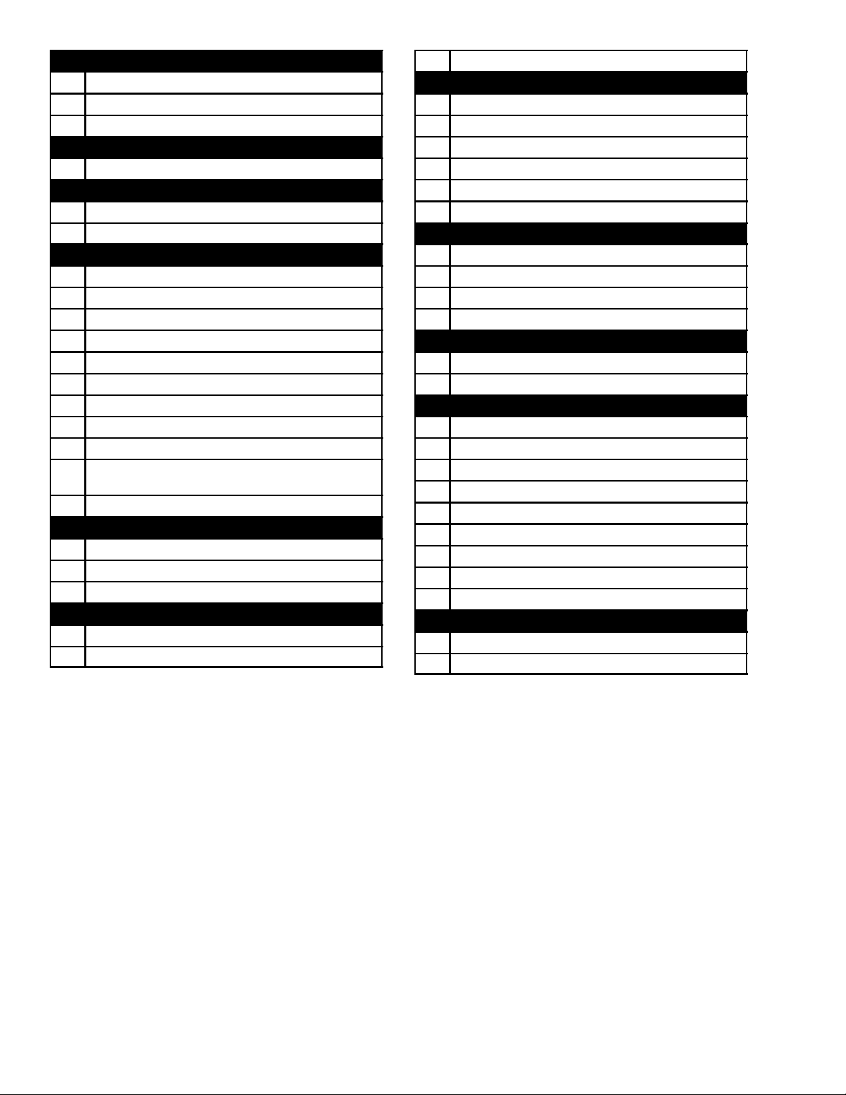
TABLE OF CONTENTS
PARAGRAPH NUMBER Page
1 QUICK LIST -- CLAMPS, FILTER--DRIER, FUSE, TY--WRAPS, WIRE TERMINALS 1...........
2 REFRIGERATION UNIT ASSEMBLY 2....................................................
2.1 REFRIGERATION UNIT -- AREA LOCATOR 2..........................................
2.2 UPPER FRESH AIR 4...............................................................
2.3 UPPER FRESH AIR -- EAUTOFRESH 10...............................................
2.4 BULKHEAD PENETRATION -- UPPER AIR EXCHANGE 14...............................
2.5 THERMOMETER PORT 15...........................................................
2.6 RAIN GUTTERS 15..................................................................
2.7 USDA 16...........................................................................
2.8 CONTROL BOX -- DOOR 18..........................................................
2.9 CONTROL BOX -- SHIELD 23.........................................................
2.10 CONTROL BOX -- WIRING 24.........................................................
2.11 CONTROL BOX -- RMU RECEPTACLE, SWITCH PANEL, NO RMU, INTERNAL VIEWS 26...
2.12 CONTROL BOX -- RMU RECEPTACLE AND SWITCH PANEL, EXTERNAL VIEW 29........
2.13 CONTROL BOX -- REMOTE MONITORING UNIT (RMU) 30..............................
2.14 CONTROL BOX -- CONTROLLER MODULE SECTION AND SOFTWARE CARDS 32........
2.15 CONTROL BOX PREPARATION 34....................................................
2.16 CONTROLLER HARDWARE, CLAMPS AND DISPLAY -- FACING VIEW 36.................
2.17 CONTROLLER HARDWARE, CLAMPS AND DISPLAY -- DETAILS 38......................
2.18 CONTROLLER HARDWARE, CLAMPS AND DISPLAY -- REAR VIEW 40...................
2.19 HANDLES 41.......................................................................
2.20 COMPRESSOR TRANSDUCERS / PRESSURE SWITCH 41..............................
2.21 COMPRESSOR, MOUNTING COMPONENTS AND GUARD 42...........................
2.22 COMPRESSOR TUBING 44..........................................................
2.23 CABLE AND COMPRESSOR GUARDS 46.............................................
2.24 ECONOMIZER 49...................................................................
2.25 RECEIVER 50.......................................................................
2.26 WATER--COOLED CONDENSER 52...................................................
2.27 CONDENSER COIL AND COVERS 54.................................................
2.28 CONDENSER FAN MOTOR 56........................................................
2.29 VOLTAGE CABLES 58...............................................................
2.30 AUTOTRANSFORMER 60............................................................
2.31 CABLE RESTRAINT COMPONENTS 63................................................
2.32 INTERROGATOR RECEPTACLE 64...................................................
2.33 VACUUM RELIEF VALVE / CONTROLLED ATMOSPHERE OPTION 66....................
2.34 DRAIN 67...........................................................................
2.35 ELECTRONIC PARTLOW TEMPERATURE RECORDER-- OPTION 9 AND OPTION P 68....
2.36 ELECTRONIC PARTLOW TEMPERATURE RECORDER -- OPTION 12 AND OPTION 13 70..
2.37 BULKHEAD PENETRATION -- LOWER AIR EXCHANGE 75..............................
2.38 LOWER FRESH AIR MAKE--UP 76....................................................
2.39 LABELS AND DECALS (Not Applicable to All Units) 78...................................
2.40 EVAPORATOR TUBING AND COIL 80.................................................
i
T-334PL

TABLE OF CONTENTS -- CONTINUED
PARAGRAPH NUMBER Page
2.41 EVAPORATOR FAN ASSEMBLY 83....................................................
2.42 HEATERS AND SENSORS (REAR PANELS REMOVED) 84..............................
2.43 BACK PANEL ASSEMBLY 86.........................................................
2.44 HARNESS -- LOW VOLTAGE 88.......................................................
2.45 HARNESS -- HIGH VOLTAGE 102......................................................
3 INTERROGATOR ACCESSORIES 108.....................................................
3.1 DATALINE/DATAREADER 108.........................................................
4 TOOLS 110..............................................................................
iiT-334PL

INTRODUCTION
1 INTRODUCTION
The Carrier Transicold model 69NT40-551-500 to 599
series units are of lightweight aluminum frame
construction, designed to fit in the front of a container
and serve as the container’s front wall.
2 CONFIGURATION IDENTIFICATION
Unit identification information is provided on a plate
located near the economizer heat exchanger, on the
back wall of the condenser section. The plate provides
the unit model number, the unit serial number and the
unit parts identification number (PID). The model
number identifies the overall unit configuration while the
PID provides information on specific optional
equipment, factory provision to allow for field installation
of optional equipment and differences in detailed parts.
Various options may be factory or field equipped to the
base unit. These options are listed in the tables and
described in the following subparagraphs.
3 OPTION DESCRIPTIONS
Various options may be factory or field fitted to the base
unit. These options are listed in the tables and described
in the following subparagraphs.
3.1 Battery
The refrigeration controller may be fitted with
rechargeable battery packs, which may be fitted in the
standard or in a secure location.
3.2 Dehumidification
The unit may be fitted with a humidity sensor. This
sensor allows setting of a humidity set point in the
controller. In dehumidification mode, the controller will
operate to reduce internal container moisture level.
3.3 Control Box
Units are equipped with either an aluminum material box
and may be fitted with a lockable door.
3.4 Temperature Readout
The unit is fitted with suction and discharge temperature
sensors. The sensor readings may be viewed on the
controller display.
3.5 Pressure Readout
The unit is fitted with suction and discharge transducers.
The transducer readings may be viewed on the
controller display.
3.6 USDA
The unit may be supplied with fittings for additional
temperature probes which allow recording of USDA
Cold Treatment data by the integral DataCORDER
function of the Micro-Link refrigeration controller.
3.7 Interrogator
Units that use the DataCORDER function are fitted with
interrogator receptacles for connection of equipment to
download the recorded data. Two receptacles may be
fitted; one is accessible from the front of the container
and the other is mounted inside the container (with the
USDA receptacles).
3.8 Remote Monitoring
The unit may be fitted with a remote monitoring
receptacle. This item allows connection of remote
indicators for COOL, DEFROST and IN RANGE.
Unless otherwise indicated, the receptacle is mounted
at the control box location.
3.9 Communications
The unit may be fitted with a communications interface
module. The communications interface module is a
slave module which allows communication with a
master central monitoring station. The module will
respond to communication and return information over
the main power line. Refer to the ship master system
technical manual for further information.
3.10 Compressor
The unit is fitted with a scroll compressor with either
standard piping (equipped with suction, discharge,
economizer and oil return service valves) or with
semi-hermetic piping (equipped with suction, discharge
and economizer service connections).
3.11 Condenser Coil
Theunitisfittedwitha4rowcoilusing7mmtubing.
3.12 Autotransformer
An autotransformer may be provided to allow operation
on 190/230, 3 phase, 50/60 hertz power. The
autotransformer raises the supply voltage to the
nominal 380/460 volt power required by the base unit.
The autotransformer may also be fitted with an
individual circuit breaker for the 230 volt power.
3.13 Temperature Recorder
The units may be fitted with an electronic temperature
recording device manufactured by the Partlow
Corporation.
3.14 Gutters
Rain gutters may be fitted over the control box and
recorder section to divert rain away from the controls.
The various gutters available include standard length
bolted gutters, extended length gutters and riveted
gutters.
iii
T-334PL

3.15 Handles
The unit may be equipped with handles to facilitate
access to stacked containers. These handles may
include fixed handles (located at the sides of the unit)
and/or a hinged handle at the center (attached to the
condenser coil cover).
3.16 Thermometer Port
The unit may be fitted with ports in the front of the frame
for insertion of a thermometer to measure supply and/or
return air temperature. If fitted, the port(s) will require a
cap and chain.
3.17 Water Cooling
The refrigeration system may be fitted with a water
cooled condenser. The condenser is constructed using
copper-nickel tube for sea water applications. The water
cooled condenser is in series with the air cooled
condenser and replaces the standard unit receiver.
When operating on the water cooled condenser, the
condenser fan is deactivated by either a water pressure
switch or condenser fan switch.
3.18 Back Panels
Back panel designs that may be fitted include panels of
aluminum and stainless steel. Panels may have access
doors and/or hinge mounting.
3.19 460 Volt Cable
Various power cable and plug designs are available for
the main 460 volt supply. Plug options tailor the cables to
each customer’s requirements.
3.20 230 Volt Cable
Units equipped with an autotransformer require an
additional power cable for connection to the 230 volt
source. Various power cable and plug designs are
available. Plug options tailor the cables to each
customer’s requirements.
3.21 Cable Restraint
Various designs are available for storage of the power
cables. These options are variations of the compressor
section front cover.
3.22 Upper Air (Fresh Air Make Up)
The unit may be fitted with an upper fresh air makeup
assembly. The fresh air makeup assembly is available
with a vent positioning sensor (VPS) and may also be
fitted with screens.
3.23 Lower Air (Fresh Air Make Up)
The unit may be fitted with a lower fresh air makeup
assembly. The fresh air makeup assembly is available
with a vent positioning sensor (VPS) and may also be
fitted with screens.
3.24 Evaporator
Evaporator section is equipped with a hermetic thermal
expansion valve. The evaporator may also be equipped
with an expansion valve bypass assembly (XBSV).
3.25 Labels
Operating Instruction and Function Code listing labels
differ, depending on the options installed. For example,
additional operating instructions are required to
describe start-up of a unit equipped with an
autotransformer. Labels available with additional
languages are listed in the parts list.
3.26 Plate Set
Each unit is equipped with a tethered set of wiring
schematic and wiring diagram plates. The plate sets are
ordered using a seven digit base part number and a two
digit dash number.
3.27 Controller
Two controllers are available:
1. Remanufactured - Controller is the equivalent of a
new OEM controller and is supplied with a 12 month
warranty.
2. Repaired - Controller has had previous faults repaired
and upgraded with the latest software.
Note: Repaired controllers are NOT to be used for
warranty repairs; only full OEM Remanufactured
controllers are to be used.
Controllers will be factory--equipped with the latest
version of operational software, but will NOT be
configured for a specific model number and will need to
be configured at the time of installation or sale.
3.28 Stepper Drive
All the units covered by this manual have suction
modulating valves which act to control system capacity.
Units indicated as being fitted with “stepper drive” have
digital control motors fitted to the suction modulating
valve to open and close the valve in steps as required.
3.29 Condenser Grille
Two styles of condenser grilles are available: direct
bolted grilles and hinged grilles.
3.30 Emergency Bypass
The unit may be equipped with switches to allow
emergency bypass of the controller. The Emergency
Bypass switch functions to bypass the controller in the
event of controller failure.
T-334PL
iv

OPTION LEGEND
General
-
X Features Installed
P Factory Installation of Equipment to
Autotransformer Codes
1 Transformer Fitted
2 Transformer With CB2 Fitted
Back Panel Codes
1 Bolted Panels
2 Hinged Panels
Battery Codes
R Rechargeable Cells
S Secure Location (Rechargeable Cells)
Bulkhead Penetration Codes
1 Not Installed
2 Installed
Cable and Compressor Guards
1 Standard Guard, 460 V Cable
2 Standard Guard, Transicord
3 Full Guard, 460 V Cable
4 Full Guard, Transicord
Cable Restraint Codes
1 Cable Door
2 Left Bungy Cord Only
3 J-Hook
R Dummy Receptacle
Communications Codes
1 Standard
2 HighDataRate
4 Low Data Rate
Compressor Codes
S Scroll
SS Scroll with Semi-Hermetic Piping
Condenser Grille Codes
B Bolted Grille
H Hinged Grille
Control Box Preparation Codes
1 Aluminum Box with Latch Fastener
2 Aluminum Box with Screw Fastener
3 Aluminum Box with Locking Screw Fastener
Feature Not Applicable
Allow Field Installation (Provision)
Control Box Shield Codes
1 High Voltage Shield
2 Low Voltage Shield
Control Box Door Codes
2 Standard Door, Slotted Screw
3 Standard Door, Wing Screw
4 Door with Flat Window, Wing Screw
5 Latching Door
Controller Components and Wiring Codes
1 Standard Wiring, No Voltage Shield
2 Wiring, No Voltage Shield, Secure Battery
3 Wiring, No Voltage Shield, EBS
4 Standard Wiring, with Voltage Shield
Evaporator Codes
7 Standard Thermostatic Expansion Valve
8 Thermostatic Expansion Valve
with Bypass Assembly
Evaporator Fan Codes
1 Single--phase Motors
3 Three--phase Motors
Rain Gutter Codes
1 Standard Length Bolted Gutters
4 Riveted Gutters
Handle Codes
2 Two Sides
High Voltage Harness Codes
1 Single--Phase Evaporator Fan Motor
2 Three--Phase Evaporator Fan Motor
Interrogator Codes
1 Left Straight Mount
3 Control Box Mount
4 Left Mount
Label Codes
1 English
2 English / Spanish
5 English / Traditional Chinese
Low Voltage Harness Codes
1 Provisioned for USDA
2 USDA Installed
3 USDA and Lower Fresh Air with VPS Installed
4 USDA and Emergency Bypass System Installed
5 USDA Installed, Single Evap. Fan Capability
6 USDA and Installed
7 USDA, Lower VPS and Installed
v
T-334PL
Lower Fresh Air Codes
1 Lower Fresh Air Not Installed
2 Lower Fresh Air Installed
4 Lower Fresh Air With Screens, VPS Installed
Pressure Readout Codes
T Pressure Transducers
Receiver Codes
1 Standard Receiver
2 Small Receiver, without King Valve
Remote Monitoring Receptacle and Switch Panel
1 No RM, Start Switch Plate
2 No RM, Start Switch Plate with Boot
3 No RM, Compressor Fan Switch Switch Plate
4 No RM, Manual Defrost (MD) Switch Plate
5 No RM, MD Switch Plate with Boot
6 No RM, Amber Defrost Light Switch Plate
7 No RM, Red Defrost Light Switch Plate
8 With Internal RM Switch Plate
9 With Internal RM, MD Switch Plate
With Internal RM, Amber Defrost Light Switch
10
Plate
11 With External RM Switch Plate
Temperature Recorder Codes
9 No Temperature Recorder
12 Special Electronic Partlow
13 Standard Electronic Partlow
Thermometer Port Codes
1 Supply Air Port
2 Return Air Port
B Both Ports
Upper Fresh Air Codes
1 Not Installed -- Access Panel Only
2 Upper Fresh Air Installed
3 Upper Fresh Air Installed With Screen
4 Upper Fresh Air Installed With VPS
5 Upper Fresh Air Installed with Screen and VPS
6 Upper Fresh Air Installed, Provisioned for VPS
USDA Codes
D Option D
V Option V
1 Option 1
2 Option 2
Vacuum Relief Valve Codes Codes
1 Vacuum Relief Valve
2 Valve with Nitrogen--Fed Controlled Atmosphere
230 and 460 Volt Cable Codes
1 Option1
2 Option 2
3 Option 3
4 Option 4
5 Option 5
6 Option 6
7 Option 7
8 Option 8
9 Option 9
Water Cooling Codes
F Condenser Fan Switch
W Water Pressure Switch
4 ORDERING INSTRUCTIONS
All orders and inquiries for parts must include: Parts Identification Number (PID), Model Number, Unit Serial Number,
Part Number, description of part as shown on list, and quantity required. Address all correspondence for parts to the
following address:
CARRIER TRANSICOLD DIVISION
Replacement Components Group, TR-20
P.O. Box 4805, Syracuse, New York 13221
or FAX to: (315) 432-3778
5 LETTER DESIGNATIONS
The following letter designations are used to classify parts throughout this list:
A/R = As Required
N/A = Not Available
NS = Not Shown in illustration
NSS = Not Sold Separately - order next higher assembly or kit
PID = Parts Identification Number - essential to identify unit configuration.
PL = Purchase Locally
SST = Stainless Steel - 300 Series unless otherwise specified.
SV = Suffix SV - added to part number designates service replacement part.
T-334PL
vi

1 QUICK LIST -- CLAMPS, FILTER--DRIER, FUSE, TY--WRAPS, WIRE TERMINALS
PART NO. DESCRIPTION
34--00373--51 Clamp, Tube, 1/4 -- SST
34--00373--53 Clamp, Tube, 3/8 -- SST
34--00373--05 Clamp, Tube, 1/2 -- SST
34--00373--07 Clamp, Tube, 5/8 -- SST
34--00373--59 Clamp, Tube, 3/4 -- SST
34--00373--11 Clamp, Tube, 7/8 -- SST
34--00373--65 Clamp, Tube, 1--1/8 -- SST
34--00373--88 Clamp, Tube, 1--1/4 -- SST
34--00373--69 Clamp, Tube, 1--3/8 -- SST
34--00373--71 Clamp, Tube, 1--1/2 -- SST
22--00066--01 Connector, Butt End, Wire Range -- 22 to 16 AWG
22--00066--02 Connector, Butt End, Wire Range -- 16 to 14 AWG
22--00066--03 Connector, Butt End, Wire Range -- 12 to 10 AWG
22--00041--00 Connector, Closed End, Wire Range -- 22 to 14 AWG
22--00041--02 Connector, Closed End, Wire Range -- 18 to 10 AWG
14--00341--04 Filter--Drier
22--02336--02 Fuse, 5 Amp (F1 and F2)
22--02336--04 Fuse, 10 Amp (FEB)
22--02336--08 Fuse, 7.5 Amp (F3A and F3B)
22--01140--01 Ring Terminal, #6, Wire Range -- 12 to 10 AWG
22--01140--02 Ring Terminal, #10, Wire Range -- 12 to 10 AWG
22--01140--04 Ring Terminal, 3/8, Wire Range -- 12 to 10 AWG
22--00119--04 Ring Terminal, 1/4, Wire Range -- 12 to 10 AWG
22--00120--04 Ring Terminal, #10, Wire Range -- 16 to 14 AWG
22--00120--07 Ring Terminal, 5/16, Wire Range -- 16 to 14 AWG
22--00121--07 Ring Terminal, #10, Wire Range -- 22 to 16 AWG
22--01139--04 Ring Terminal, 3/8, Wire Range -- 16 to 14 AWG
22--01141--01 Spade Terminal, 1/4 X 5/16, Wire Range -- 16 to 14 AWG
22--00595--01 Spade Terminal, 3/8, Wire Range -- 12 to 10 AWG
22--01106--00 Spiral Wrap, 1/4 Diameter X 25 ft. Long
22--01107--00 Spiral Wrap, 1/2 Diameter X 25 ft. Long
66U1--3803 Tube, Heat Shrink, 1/4 ID X 2--1/8 Long
66U1--3803--1 Tube, Heat Shrink, 1/2 ID X 2--3/4 Long
44--01043--05 Ty--Wraps, 5--1/2 inches Long
44--01043--07 Ty--Wraps, 11.00 inches Long
22--50007 Series Wire Markers
07--00345--00 Sealant, Pipe (Used to seal fittings on unit with R--134a)
07--00313--00 Cleaner, Coil
1 T-334PL
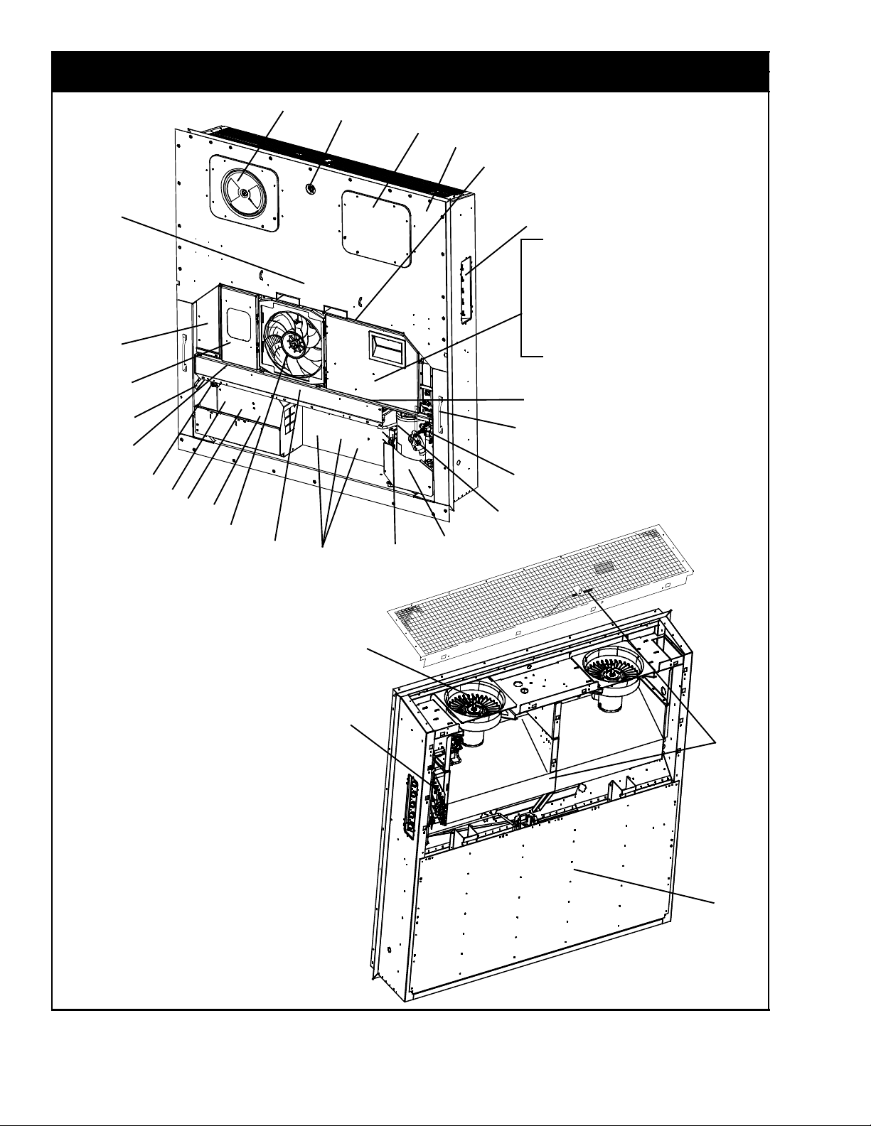
2 REFRIGERATION UNIT ASSEMBLY
2.1 REFRIGERATION UNIT -- AREA LOCATOR
1
2
4
1
2
3
5
38
36
37
34
35
33
32
31
30
29
28
27
26
23
24
25
21
6
7
8
9
10
11
12
13
14
15
16
17
18
19
20
22
39
40
41
42
2T-334PL

2.1 REFRIGERATION UNIT -- AREA LOCATOR (Continued)
Item Section Number Area Description
1 Refer to Section 2.2 Upper Fresh Air
2 Refer to Section 2.3 Upper Fresh Air -- eAutoFresh
3 Refer to Section 2.4 Bulkhead Penetration -- Upper Air Exchange
4 Refer to Section 2.5 Thermometer Port
5 Refer to Section 2.6 Rain Gutters
6 Refer to Section 2.7 USDA
7 Refer to Section 2.8 Control Box -- Door
8 Refer to Section 2.9 Control Box -- Shield
9 Refer to Section 2.10 Control Box -- Wiring
10 Refer to Section 2.11 Control Box -- RMU Receptacle and Switch Panel -- No RM and Internal Views
11 Refer to Section 2.12 Control Box -- RMU Receptacle and Switch Panel -- External View
12 Refer to Section 2.13 Control Box -- Remote Monitoring Unit (RMU)
13 Refer to Section 2.14 Control Box -- Controller Module Section and Software Cards
14 Refer to Section 2.15 Control Box Preparation
15 Refer to Section 2.16 Controller Hardware, Clamps and Display -- Facing View
16 Refer to Section 2.17 Controller Hardware, Clamps and Display -- Details
17 Refer to Section 2.18 Controller Hardware, Clamps and Display -- Rear View
18 Refer to Section 2.19 Handles
19 Refer to Section 2.20 Compressor Transducers / Pressure Switch
20 Refer to Section 2.21 Compressor, Mounting Components and Guard
21 Refer to Section 2.22 Compressor Tubing
22 Refer to Section 2.23 Cable and Compressor Guards
23 Refer to Section 2.24 Economizer
24 Refer to Section 2.25 Receiver
25 Refer to Section 2.26 Water--Cooled Condenser
26 Refer to Section 2.27 Condenser Coil and Covers
27 Refer to Section 2.28 Condenser Fan Motor
28 Refer to Section 2.29 Voltage Cables
29 Refer to Section 2.30 Autotransformer
30 Refer to Section 2.31 Cable Restraint Components
31 Refer to Section 2.32 Interrogator Receptacle
32 Refer to Section 2.33 Vacuum Relief Valve / Controlled Atmosphere
33 Refer to Section 2.34 Drain
34 Refer to Section 2.35 Electronic Temperature Recorder -- Options 9 and P
35 Refer to Section 2.36 Electronic Temperature Recorder -- Options 12 and 13
36 Refer to Section 2.37 Bulkhead Penetration -- Lower Air Exchange
37 Refer to Section 2.38 Lower Fresh Air Make--up
38 Refer to Section 2.39 Labels and Decals
39 Refer to Section 2.40 Evaporator Tubing and Coil
40 Refer to Section 2.41 Evaporator Fan Assembly
41 Refer to Section 2.42 Heaters and Sensors
42 Refer to Section 2.43 Back Panel Assembly
NS Refer to Section 2.44 Harness -- Low Voltage
NS Refer to Section 2.45 Harness -- High Voltage
NS Refer to Section 3.1 DataLine/Data Reader
3 T-334PL
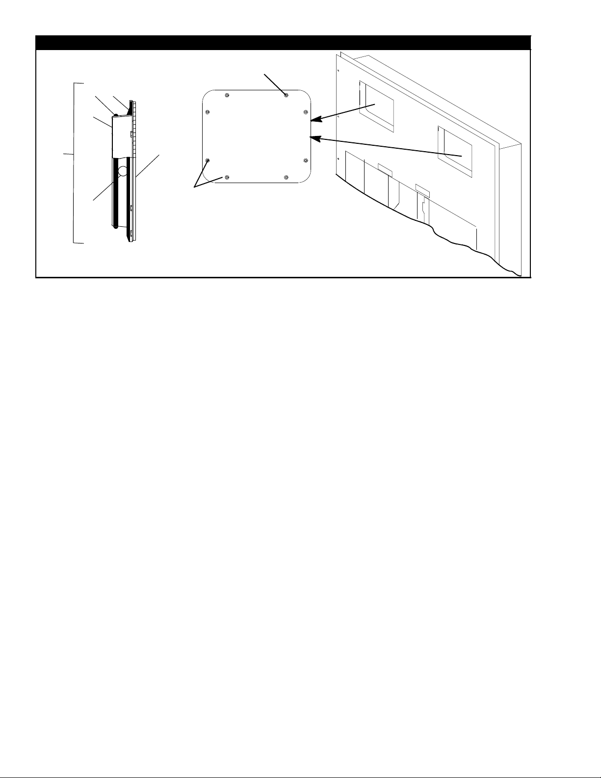
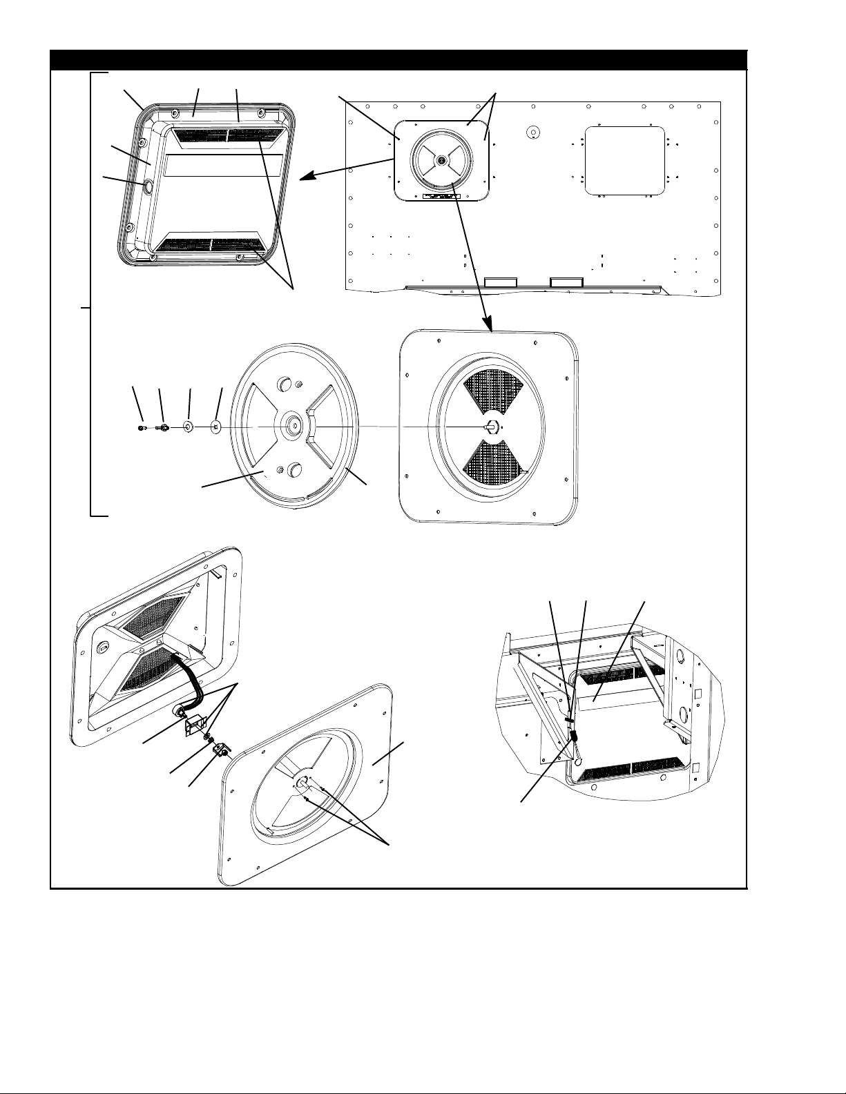
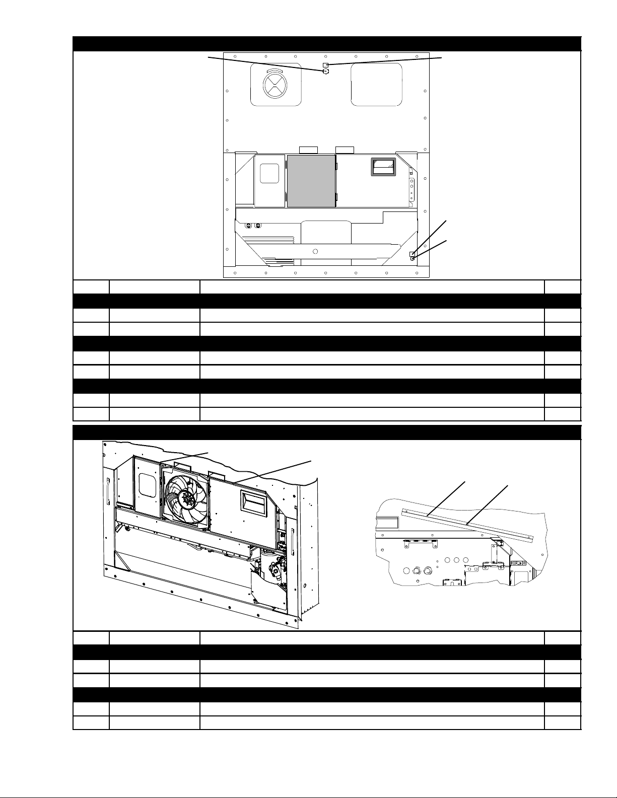
2.2 UPPER FRESH AIR
4
3
2
10, 8, 9
1
6
SIDE VIEW
5
7, 8, 9
FRONT VIEW
FOR TI R EQUIPPED UNITS
- LOCATION OPTIONAL
OPTION 1
4T-334PL

2.2 UPPER FRESH AIR (Continued)
Item Part Number Description Qty
OPTION 1 - ACCESS PANEL ONLY
79-01697-06SV Panel Assembly, Access, Evaporator, White -- Includes: A/R
1
79-01697-17SV Panel Assembly, Access, Evaporator, Orange -- Includes: A/R
2 58-04378-01 Panel, Access 1
3 42-00327-00 Gasket, 0.26 x 0.50 Half-round 1
4 42-00296-01 Gasket, Evaporator Access Panel 1
68-11989-00 Cover, Top, Evaporator Access Panel, White A/R
5
68-11989-01 Cover, Top, Evaporator Access Panel, Orange A/R
6 66U1-5562-2 Plug Button 1
7 34-06154-00 Screw, Hex Head, 1/4-20 x 1.00 Long - TIR A/R
8 34-06053-13 Washer, Mylar 8
9 34-06212-12 Washer, Plain - 1/4 8
10 34-00655-08 Screw, Hex Head, 1/4-20 x 1.00 Long A/R
5 T-334PL
2.2 UPPER FRESH AIR (Continued)
3
2
BACK OF FRESH
AIR PANEL
1
91210611
54
20
(OPTION 3 ONLY)
13,
14, 19
13,14,18
(POSITION OPTIONAL)
25
24
23
7
8
OPTIONS 2, 3, and 4
15
16
21
OPTION 5 - VPS
26
3
27
28
17 or
29
30
22
6T-334PL

2.2 UPPER FRESH AIR (Continued)
Item Part Number Description Qty
STANDARD P ARTS FOR OPTIONS 2, 3 and 4
1 79-01695-00 Panel Assembly, Access -- Includes: 1
2 58-04376-03 Panel, Access 1
3 68-12940-00 Cover, Top, Evaporator Access Panel 1
4 42-00296-01 Gasket, Evaporator Access Panel 1
5 42-00327-00 Gasket, 0.26 x 0.50 Half-Round 1
6 66U1-5562-2 Plug Button, 1.25 Diameter Hole 1
7 68-12933-00 Disc, 12.35 Diameter 1
8 42-00407-00 Gasket, 0.50 Fresh Air Disc 1
9 34-06185-01 Screw, Machined, #8-32 x 0.50 with Nylock 1
10 66U1-5362-2 Nut, Wing, 5/16-18 - SST 1
11 66U1-5321-13 Washer, Plain 5/16 W Type A - SST 1
12 34-06053-19 Washer, Mylar 1.00 OD x 0.312 ID 1
13 34-06053-13 Washer, Mylar, 1/4 ID x 0.80 OD 8
14 34-006212-12 Washer, Flat, 1/4 - SST 8
15 66CH1-1172-2 Trim, Flexible 2.00 Long 1
16 58-00969-00 Wire Tie 2.80 Diameter, Double Loop 1
17 66U1-8292-1 Cap, Insulating 0.125 OD Black 3
7 T-334PL

2.2 UPPER FRESH AIR (Continued)
Item Part Number Description Qty
OPTION 2 - UPPER FRESH AIR INSTALLED WITH STANDARD FASTENERS
See Previous Section for Standard Parts and use with Items Below:
18 34-06154-00 Screw, Hex Head, 1/4-20 x 1.00 Long - TIR 2
19 34-00655-08 Screw, Hex Head, 1/4-20 x 1.00 Long 6
OPTION 3 - UPPER FRESH AIR INSTALLED WITH SCREENS
See Previous Section for Standard Parts and use with Items Below:
18 34-06154-00 Screw, Hex Head, 1/4-20 x 1.00 Long - TIR 2
19 34-00655-08 Screw, Hex Head, 1/4-20 x 1.00 Long 6
20 58-04251-00 Screen, Medfly, USDA, 16 x 16 2
OPTION 4 - UPPER FRESH AIR INSTALLED WITH STAINLESS STEEL FASTENERS
See Previous Section for Standard Parts and use with Items Below:
18 34-66627-00 Screw, Hex Head, 1/4-20 x 1.00 Long - TIR 2
19 66U1-5361-50 Screw, Hex Head, 1/4-20 x 1.00 Long 6
8T-334PL

2.2 UPPER FRESH AIR (Continued)
Item Part Number Description Qty
OPTION 5 - VENT POSITIONING SENSOR INSTALLED
79-66626-00 Panel Assembly, Access, White -- Includes: A/R
1
79-66626-01 Panel Assembly, Access, Orange -- Includes: A/R
2 58-04376-05 Panel, Access 1
68-12940-05 Cover, Top, Evaporator Access Panel, White A/R
3
68-12940-03 Cover, Top, Evaporator Access Panel, Orange A/R
4 42-00296-01 Gasket, Evaporator Access Panel 1
5 42-00327-00 Gasket, 0.26 x 0.50 Half-round 1
6 66U1-5562-2 Plug Button, 1.25 Diameter Hole 1
68-12933-07 Disc, 12.35 Diameter, White A/R
7
68-12933-05 Disc, 12.35 Diameter, Orange A/R
8 42-00407-00 Gasket, 0.50 Fresh Air Disc 1
9 34-06185-01 Screw, Pan Head, #8-32 x 0.50 with Nylock 1
10 66U1-5362-2 Nut, Wing, 5/16-18 - SST 1
11 66U1-5321-13 Washer, Plain 5/16 W Type A - SST 1
12 34-06053-19 Washer, Mylar 1.00 OD x 0.312 ID 1
21 66U1-2552-185 Gasket 1
13 34-06053-13 Washer, Mylar, 1/4 ID x 0.80 OD 8
14 34-06212-12 Washer, Flat, 1/4 - SST 8
15 66CH1-1172-2 Trim, Flexible 2.00 Long 1
16 58-00969-00 Wire Tie 2.80 Diameter, Double Loop 1
17 66U1-8292-1 Cap, Insulating 0.125 OD Black (NOT USED IN THIS ASSEMBLY) 3
18 34-06154-00 Screw, Hex Head, 1/4-20 x 1.00 Long - TIR 2
19 34-00655-08 Screw, Hex Head, 1/4-20 x 1.00 Long 6
20 58-04251-00 Screen, Medfly, USDA, 16 x 16 (NOT USED IN THIS ASSEMBLY) 2
22 34-00928-02 Rivet, Blind 0.125 Diameter 0.126-0.187 2
23 NSS Nut, Self Lock, 1/4-20 1
24 NSS Plate 2
25 NSS Bracket, Sensor 2
26 NSS Sensor, Rotary Position 1
27 22-01613-10 Plug, 4-Pin 1
28 22-01613-13 Contact, Socket #16 3
29 22-01613-11 Lock, 4-Pin - Secondary 1
30 22-01660-08 Plug, 0.12 Diameter x 0.58 1
9 T-334PL
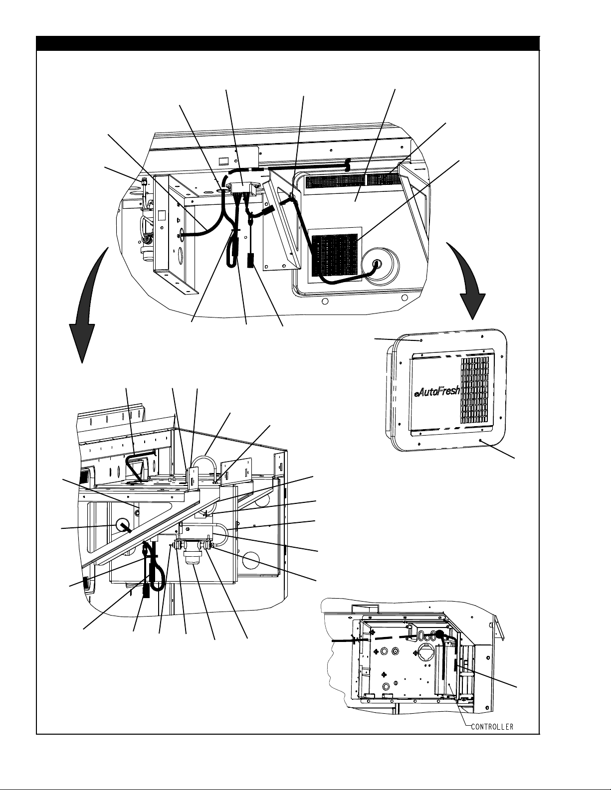
2.3 UPPER FRESH AIR -- EAUTOFRESH
5
6
3
4
2
1
10
7
14
10
13
10
8
9
FOR PANEL ASSEMBLY,
SEE PAGE 12--13
11
12
15
16
17
34
35
36
37
33
19
2
6
7
10
31
32
3
10
29
30
20
26
21
22
23
16
17
22
10
24
6
25
26
27
6
28
6
26
18
38
10T-334PL

2.3 UPPER FRESH AIR -- EAUTOFRESH (Continued)
Item Part Number Description Qty
1 40--00601--05 Tube, Support 1/4 OD X 0.040 W 1
2 22--01713--26 Harness, eAutoFresh, ML3 (SEE SECTION 2.44, OPTION 8) 1
3 22--01713--20 Harness, Plug (SEE SECTION 2.44, OPTION 8) 1
4 58--00065--77 Grommet, 0.38 ID X 1.25 OD 1
5 10--00388--00 Powerpack, Stepper Motor 1
6 66U1--5371--6 Screw, Mach Hex Head #10--24 X 0.750 Slotted 10
7 66U1--5321--8 Washer, Plain #10 Type A 4
8 66CH1--1172--2 Trim, Flexible 2.00 Long 1
9 44--00361--00 Clip, Retaining 0.88--1.00 Wire Mtg 2
10 66U1--3882 Wire Tie 1/16--1--3/4 Selflocking 11
11 58--04251--01 Screen, 16 X 16 Mesh 1
12 58--04251--02 Screen, 16 X 16 Mesh 1
13 22--01713--21 Harness, Plug (SEE SECTION 2.44, OPTION 8) 1
14 22--01835--00 Connector, 5 Socket Weatherpack 1
15 34--06154--00 Screw, Captive Hex Head 1/4--20 X 1.00 TIR 2
16 34--06053--13 Washer, Retaining 0.19 ID X 0.80 OD (0.250) 8
17 34--06212--12 Washer, Plain 1/4 N Type A 8
18 34--00655--08 Screw, Captive Hex Head 1/4--20 X 1.00 6
19 68--14739--00 Bracket, 0.063 Thick Alum 1
20 34--00928--03 Rivet, Blind 0.125 Diameter 0.188--0.250 2
21 58--00065--84 Grommet, 0.25 X 0.50 X 0.187 Panel 1
22 58--04497--01 Tube, 1/4 OD X 6.25 L 2
23 40--00640--00 Union, Bulkhead Double Brb/Comp Align 1
24 58--04497--04 Tube, 1/4 OD X 7.75 L 1
25 68--14738--00 Bracket, Mounting 0.090 Thk Alum 1
26 34--00373--07 Clamp, Tube 0.62 Diameter Cushion 2
27 KA70PP048 Fitting, Hose 1/8 ID Barb X 1/8 NPT 1
28 30--00415--01 Filter Assembly, Sample Air, 1/8 NPT 1
29 40--00297--00 Coupling, 1/8 X 1/8 Pipe Thread 2
30 40--00108--03 Coupling, Half Union 1
31 22--01613--08 Receptacle, 4 Pin 1
32 22--01613--09 Lock, Secondary 4 Pin (R) 1
33 58--00065--78 Grommet, 0.25 ID X 1.25 OD 1
34 10--00398--00 Sensor Carbon Dioxide -- Includes: 1
35 22--01613--10 Plug 1
36 22--01613--11 Lock 1
37 22--06163--15 Socket 1
38 22--01777--03 Contact Socket, 20 AWG 7
11 T-334PL
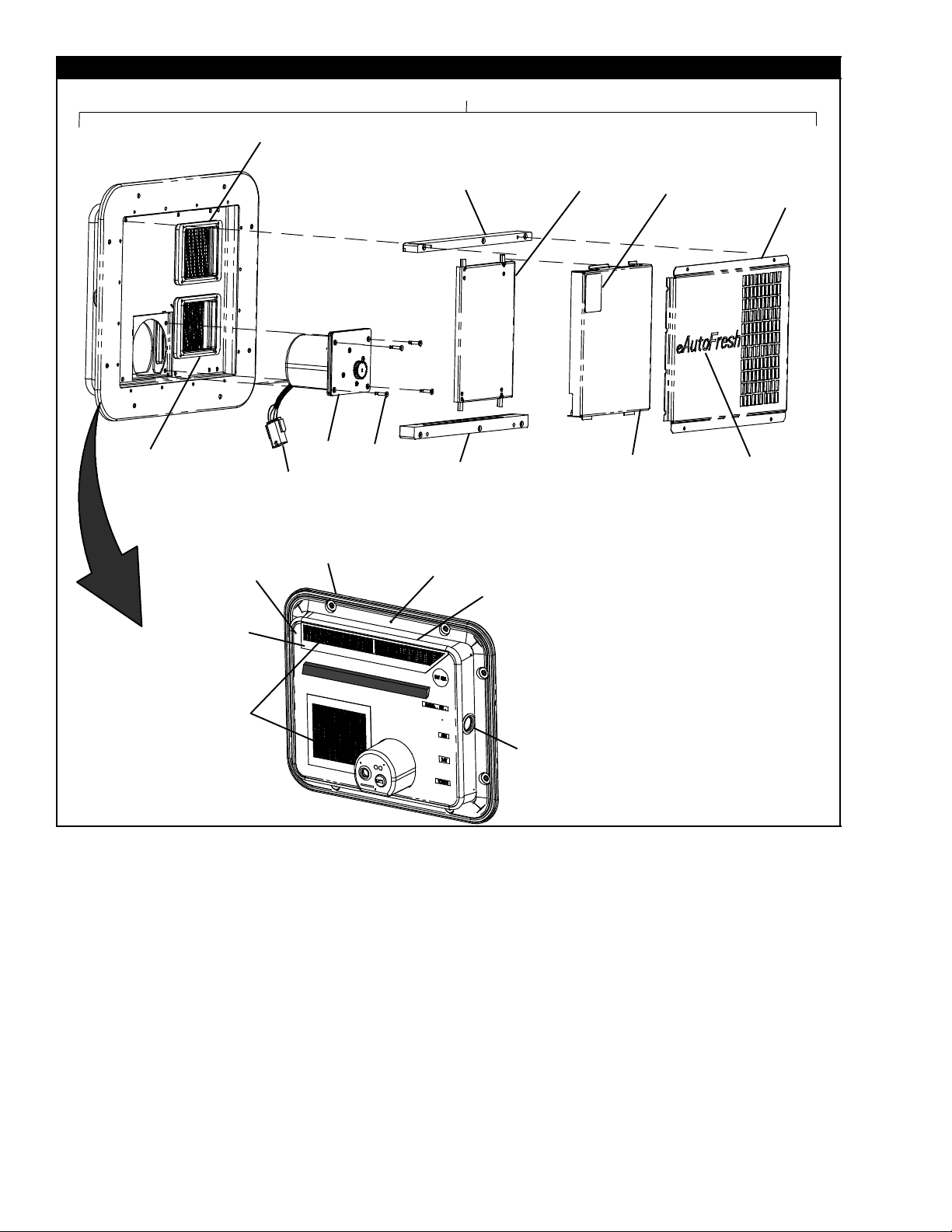
2.3 UPPER FRESH AIR -- EAUTOFRESH (Continued)
10
11
1
12
13
14
15
16
13
14
17
18
10
11
2
FOR SCREENS,
SEE PAGES 10 --11
23
24
4
3
5
6
22
13
14
21
7
8
9
20
19
12T-334PL

2.3 UPPER FRESH AIR -- EAUTOFRESH (Continued)
Item Part Number Description Qty
79--66643--00 eAutoFresh White Panel Includes: A/R
1
79--66643--01 eAutoFresh Orange Panel Includes: A/R
2 66U1--2552--185 Gasket 1
3 58--66642--00 Panel Assembly -- Includes: 1
68--11989--08 Cover, Access, White A/R
4
68--11989--10 Cover, Access, Orange A/R
5 34--00928--09 Rivet, Blind 16
86--66704--00 Box Assembly, Recess, White A/R
6
86--66704--01 Box Assembly, Recess, Orange A/R
7 42--00296--01 Gasket 1
8 42--00327--00 Gasket 1
9 66U1--5562--2 Plug Button 1
10 58--66640--00 Collar 2
11 34--00928--06 Rivet, Blind 8
12 58--66644--00 Rail Top 1
13 66U1--6651--26 Screw, Machine Pan Head 12
14 34--00662--08 Washer, Plain 15
15 79--66640--00 Plate Assembly -- Slide 1
16 62--66697--00 Label Warning, eAutoFresh 1
68--14715--00 Grille, White A/R
17
68--14715--01 Grille, Orange A/R
18 58--04026--56 Protector 7
19 62--66701--00 Label, eAutoFresh 1
20 79--66642--00 Plate Assembly -- Gasket 1
21 58--66645--00 Rail Bottom 1
22 34--66642--09 Screw, Flat Head 4
79--66641--00 Cup Assembly, White -- Includes: A/R
23
79--66641--01 Cup Assembly, Orange -- Includes: A/R
24 22--02392--03 Connector, Female 1
13 T-334PL
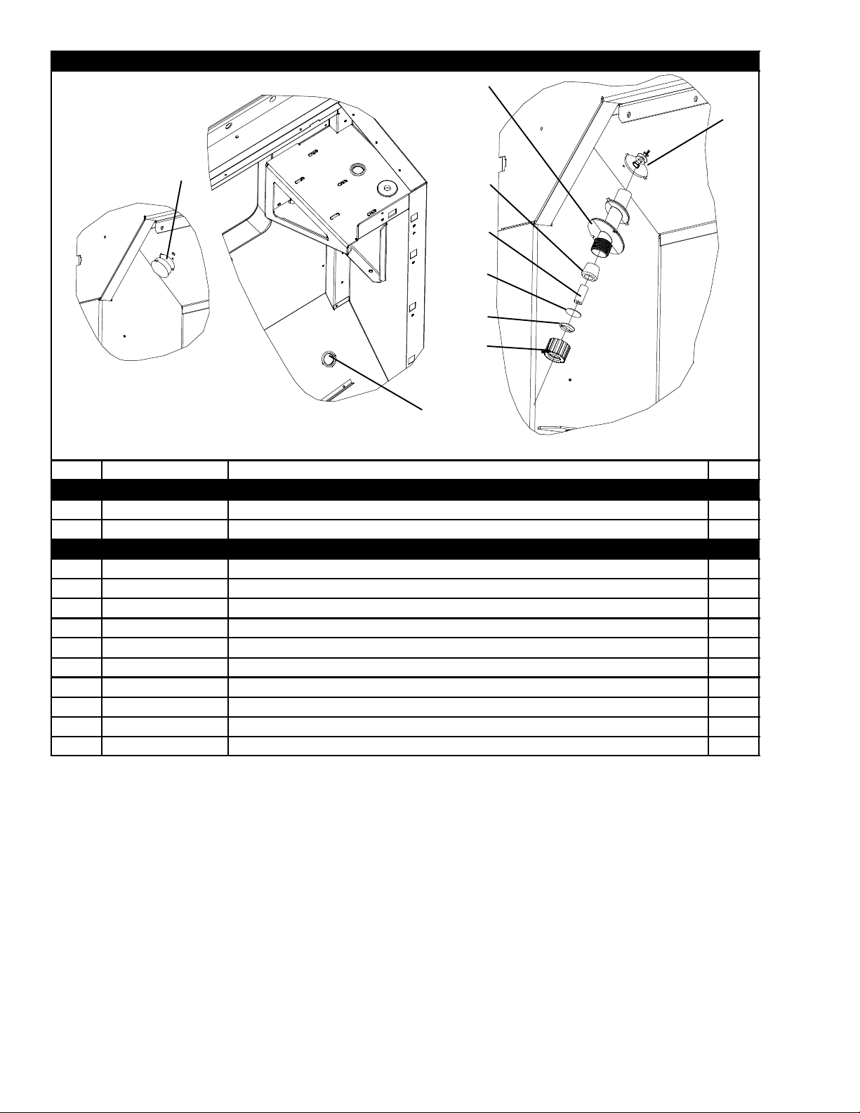
2.4 BULKHEAD PENETRATION -- UPPER AIR EXCHANGE
3
4
10
11
12
1
2
OPTION 1 OPTION 2
Item Part Number Description Qty
OPTION 1 -- NOT INSTALLED
1 58--00616--00 Plug, Hole 2.00 Diameter X 0.12 Panel 1
2 66U1--5562--2 Plug Button, 1.25 Diameter Hole 1
OPTION 2 -- STANDARD INSTALLED
3 58--04290--01 Fitting, Bulkhead 1
4 34--00928--04 Rivet, Blind, 1/8 Diameter, Grip Range 1/4 -- 5/16 4
5 22--01602--02 Bushing, 0.625 ID X 0.88 Long 1
6 58--04302--01 Grommet, 0.25 ID X 1.25 Long 1
7 69NT35--8258 Disc, 0.040 Thick Aluminum 1
8 22--01602--03 Gotcha Ring, 0.312--0.375 1
9 22--01733--01 Nut, Straight (with TIR Holes) 1
10 34--06154--00 Screw, Captive Hex Head 1/4--20 X 1.00 TIR 1
11 34--06053--00 Washer, 0.250 ID X 0.800 OD 1
12 66U1--5321--7 Washer, Plain 1/4 W Type A 1
5
6
7
8
9
14T-334PL
2.5 THERMOMETER PORT
3
Item Part Number Description Qty
OPTION 1 -- SUPPLY AIR PORT
1 66U1--8662 Cap and Chain Assembly 1
2 62--10557--00 Label 1
OPTION 2 -- RETURN AIR PORT
3 66U1--8662 Cap and Chain Assembly 1
4 62--10557--00 Label 1
OPTION B -- SUPPLY AND RETURN PORTS
1, 3 66U1--8662 Cap and Chain Assembly 2
2, 4 62--10557--00 Label 2
4
2
1
2.6 RAIN GUTTERS
1
Item Part Number Description Qty
OPTION 1 -- BOLTED
1 69NT35--3997--1 Gutter, Rain (Bolted, Standard -- Left Side) 1
2 69NT35--3987 Gutter, Rain (Bolted, Standard -- Right Side) 1
OPTION 4 -- RIVETED
3 68--12417--00 Gutter, Rain (Riveted -- Right and Left Side) 2
4 34--00928--13 Rivet, Blind 0.187 Diameter 0.126--0.250 6
2
3
4
15 T-334PL
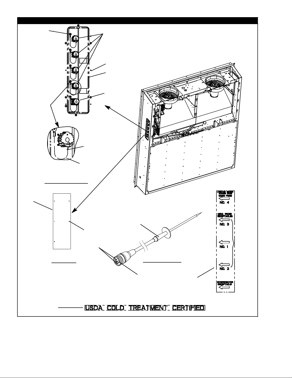
2.7 USDA
9
10
2
1
2
3
4
5
6
4
7
8
13
OPTIONS D AND V
14
OPTION P
12
16
15
OPTION 1 OR 2
17
11
16T-334PL

2.7 USDA (Continued)
Item Part Number Description Qty
OPTION D
1 Receptacle (PR1, PR2, PR3, Cargo Probe 4) (3--Pin) (RefertoSection2.44)
2 69NT35--636--1 Tether Assembly 5
3 22--01660--02 Cap, Dust, (3--Pin Receptacle) 4
4 22--01660--08 Plug, Sealing 4
5 66U1--5371--7 Screw, Mach Hex Head, #10--24 X 0.500 Slotted 7
6 68--14444--00 Panel Assembly, 0.063 Thick Alum 1
7 Receptacle, Interrogator (ICR),5--Pin(RefertoSection2.44)
8 22--01660--05 Cap, Dust (5--Pin Receptacle) 1
9 34--06142--00 Rivet, 0.110 Diameter 0.126--.250 25
10 22--02205--00 Connector Splice, Non--insulated 5
NS 66U1--3882 Wire Tie, 1/16--1--3/4 Self--Locking 4
11 69NT35--6118 Label, USDA 1
12 62--10902--03 Label, MI3, USDA, Blue 1
OPTION V
1 Receptacle (PR1, PR2, PR3, Cargo Probe 4) (3--Pin) (RefertoSection2.44)
4 22--01660--08 Plug, Sealing 4
5 66U1--5371--7 Screw, Machine Hex Head, #10--24 X 0.500 Slotted 7
6 68--14444--01 Panel Assembly, 0.063 Thick Aluminum 1
7 Receptacle, Interrogator (5--Pin) (RefertoSection2.44)
8 22--02413--00 Cap, Dust, 5--Pin 1
10 22--02205--00 Connector, Splice, Non--Insulated 4
2 69NT35--636--1 Tether Assembly 4
3 22--01660--02 Cap, Dust, 3--Pin Receptacle 4
9 34--06142--00 Rivet, 0.110 Diameter 0.126--.250 25
NS 66U1--3882 Wire Tie, 1/16-- 1--3/4, Self--Locking 4
11 62--11274--00 Label, USDA 1
OPTION P
13 68--14628--00 Plate 1
14 34--00928--09 Rivet, Blind, 0.156 Diameter 6
FIELD INSTALLED KITS (FOR UNITS WITH USDA PROVISIONS)
76--00676--00 Kit, USDA (For field installation, units provisioned for side--mounted
--
USDA PROBE KITS
OPTION 1
15 12--50089--00 Sensor Assembly, 600” Long (15M) (USDA Probe) -- Includes: A/R
16 22--50127--00 Plug, Socket (PR1, PR2, PR3, Cargo Probe 4) 1
17 22--01613--15 Contact, Socket, #16 (Used with 22--50127--00 and 22--01660--04) A/R
OPTION 2
12--00342--04 Sensor Assembly, Customer Specific, 600” Long (15M) (USDA Probe) --
15
16 22--50127--00 Plug, Socket (PR1, PR2, PR3, Cargo Probe 4) 1
17 22--01613--15 Contact, Socket, #16 (Used with 22--50127--00 and 22--01660--04) A/R
USDA) -- Includes all of OPTION D
A/R
Includes:
--
17 T-334PL
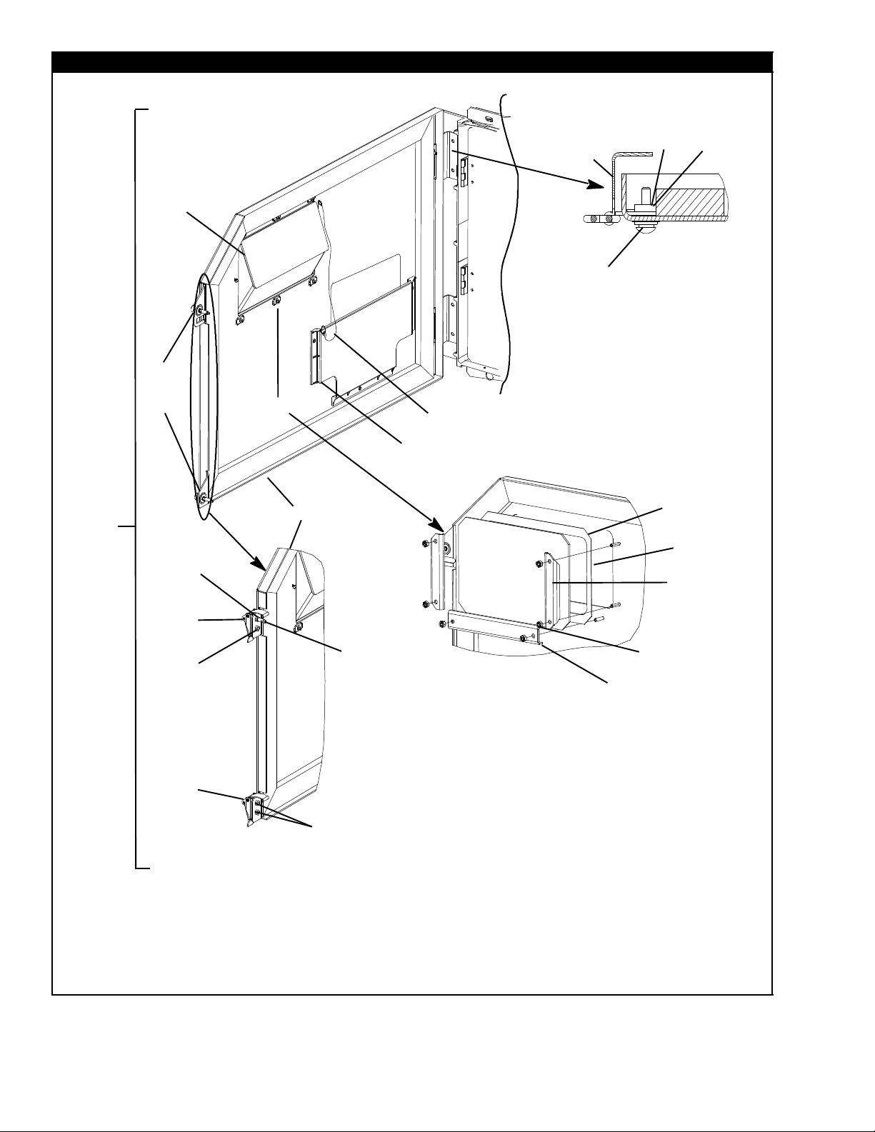
2.8 CONTROL BOX -- DOOR
6
3
4
5
17
14
15
16
7
9
10
11
12
8
13
2
1
25
26
27
23
24
26
28
29
23
24
OPTION 5 -- LATCHING DOOR
28
30
22
OPTION 4 -- FLAT WINDOW
26
27
29
18
19
20
21
18T-334PL

2.8 CONTROL BOX -- DOOR (Continued)
Item Part Number Description Qty
OPTION 2 -- DOOR ASSEMBLY, BLUE, SLOTTED FASTENERS
1 74--66608--00 Door Assembly, Blue, with Slotted Fasteners -- Includes:
2 86--04461--00 Door, Control Box 1
3 66U1--6811--8 Screw, Retaining 0.300--0.625, Slotted 2
4 34--06053--00 Washer, 0.250 ID X 0.800 OD 4
5 34--06169--00 Washer, Retaining 0.185 ID X 0.62 OD 2
6 42--00270--02 Gasket, Control Box Door 1
7 44--00300--00 Hinge Assembly, With Tethered Pin 2
8 34--01167--01 Nut, Retainer 10--24 X 1.75 2
9 66U1--2403--1 Screw, 10--24 X 0.750 Slotted 4
10 34--00663--09 Washer, Lock 10 Spring 4
11 66U1--5321--8 Washer, Plain 10 Type A 4
12 34--06053--05 Washer, 0.205 ID X 0.600 OD 4
13 58--04101--00 Protector 1.00 X 2.63 2
14 34--06107--00 Rivet, Blind, 0.125 Diameter 0.188--0.250 3
15 58--04389--00 Pocket 1
16 66U1--3882 Wire Tie, 1/16--1--3/4, Self--Locking 2
17 58--04366--00 Window, Controller Door 1
OPTION 3 -- DOOR ASSEMBLY, BLUE, WING FASTENERS
1 74--66608--02 Door Assembly, Blue, with Wing Fasteners -- Includes:
2 86--04461--00 Door, Control Box 1
3 66U1--6811--15 Screw, Retaining 0.300--0.625, Wing 2
4 34--06053--00 Washer, 0.250 ID X 0.800 OD 4
5 34--06169--00 Washer, Retaining 0.185 ID X 0.62 OD 2
6 42--00270--02 Gasket, Control Box Door 1
7 44--00300--00 Hinge Assembly, With Tethered Pin 2
8 34--01167--01 Nut, Retainer 10--24 X 1.75 2
9 66U1--2403--1 Screw, 10--24 X 0.750 Slotted 4
10 34--00663--09 Washer, Lock 10 Spring 4
11 66U1--5321--8 Washer, Plain 10 Type A 4
12 34--06053--05 Washer, 0.205 ID X 0.600 OD 4
13 58--04101--00 Protector 1.00 X 2.63 2
14 34--06107--00 Rivet, Blind, 0.125 Diameter 0.188--0.250 3
15 58--04389--00 Pocket 1
16 66U1--3882 Wire Tie, 1/16--1--3/4, Self--Locking 2
17 58--04366--00 Window, Controller Door 1
19 T-334PL

2.8 CONTROL BOX -- DOOR (Continued)
Item Part Number Description Qty
OPTION 4 -- DOOR ASSEMBLY, BLUE, WING FASTENERS AND FLAT WINDOW
1 74--66608--03 Door Assembly, Blue, with Wing Fasteners and Flat Window -- Includes:
2 86--04461--00 Door, Control Box 1
3 66U1--6811--15 Screw, Retaining 0.300--0.625, Wing 2
4 34--06053--00 Washer, 0.250 ID X 0.800 OD 4
5 34--06169--00 Washer, Retaining 0.185 ID X 0.62 OD 2
6 42--00270--02 Gasket, Control Box Door 1
7 44--00300--00 Hinge Assembly, With Tethered Pin 2
8 34--01167--01 Nut, Retainer 10--24 X 1.75 2
9 66U1--2403--1 Screw, 10--24 X 0.750 Slotted 4
10 34--00663--09 Washer, Lock 10 Spring 4
11 66U1--5321--8 Washer, Plain 10 Type A 4
12 34--06053--05 Washer, 0.205 ID X 0.600 OD 4
13 58--04101--00 Protector 1.00 X 2.63 2
14 34--06107--00 Rivet, Blind, 0.125 Diameter 0.188--0.250 3
15 58--04389--00 Pocket 1
16 66U1--3882 Wire Tie, 1/16--1--3/4, Self--Locking 2
17 NSS Window Assembly, Flat -- Includes: 1
18 42--00611--00 Foam, Double Coated 1
19 69NT35--5022-- 6 Window 1
20 68--14817--00 Bracket, Mounting 2
21 34--00795--09 Nut, Self Lock 10--32 6
22 68--13724--00 Bracket, Mounting 1
OPTION 5 -- DOOR ASSEMBLY, BLUE, LATCHES
1 74--66608--04 Door Assembly, Blue, with Latches -- Includes:
2 86--66688--01 Door, Control Box, Latch 1
6 42--00270--02 Gasket, Control Box Door 1
7 44--00300--00 Hinge Assembly, With Tethered Pin 2
8 34--01167--01 Nut, Retainer 10--24 X 1.75 2
9 66U1--2403--1 Screw, 10--24 X 0.750 Slotted 4
10 34--00663--09 Washer, Lock 10 Spring 4
11 66U1--5321--8 Washer, Plain 10 Type A 4
12 34--06053--05 Washer, 0.205 ID X 0.600 OD 4
13 58--04101--00 Protector 1.00 X 2.63 2
14 34--06107--00 Rivet, Blind, 0.125 Diameter 0.188--0.250 3
15 58--04389--00 Pocket 1
16 66U1--3882 Wire Tie, 1/16--1--3/4, Self--Locking 2
17 58--04366--00 Window 1
23 58--04026--74 Protector, Latch 2
24 44--66605--00 Latch 2
25 66U1--6651--22 Screw, Mach Pan Head 8--32 X 3/4 1
26 34--00663--08 Washer, Lock 4
27 66U1--5321--2 Washer, Plain 4
28 34--66621--04 Washer, Lock 1
29 66U1--6651--2 Screw, Mach Pan Head 8--32 X 1/2 3
30 48--66611--00 Pin, Guide 1
20T-334PL

2.8 CONTROL BOX -- DOOR (Continued)
Item Part Number Description Qty
OPTION 6 -- DOOR ASSEMBLY, BLUE, PHILLIPS FASTENERS
1 74--66608--01 Door Assembly, Blue, with Phillips Fasteners -- Includes:
2 86--04461--00 Door, Control Box 1
3 66U1--6811--12 Screw, Retaining 0.300--0.625, Phillips 2
4 34--06053--00 Washer, 0.250 ID X 0.800 OD 4
5 34--06169--00 Washer, Retaining 0.185 ID X 0.62 OD 2
6 42--00270--02 Gasket, Control Box Door 1
7 44--00300--00 Hinge Assembly, With Tethered Pin 2
8 34--01167--01 Nut, Retainer 10--24 X 1.75 2
9 66U1--2403--1 Screw, 10--24 X 0.750 Slotted 4
10 34--00663--09 Washer, Lock 10 Spring 4
11 66U1--5321--8 Washer, Plain 10 Type A 4
12 34--06053--05 Washer, 0.205 ID X 0.600 OD 4
13 58--04101--00 Protector 1.00 X 2.63 2
14 34--06107--00 Rivet, Blind, 0.125 Diameter 0.188--0.250 3
15 58--04389--00 Pocket 1
16 66U1--3882 Wire Tie, 1/16--1--3/4, Self--Locking 2
17 58--04366--00 Window, Controller Door 1
OPTION 6 -- DOOR ASSEMBLY, ORANGE, PHILLIPS F ASTENERS
1 74--66608--05 Door Assembly, Orange, with Phillips Fasteners -- Includes:
2 86--04461--02 Door, Control Box 1
3 66U1--6811--12 Screw, Retaining 0.300--0.625, Phillips 2
4 34--06053--00 Washer, 0.250 ID X 0.800 OD 4
5 34--06169--00 Washer, Retaining 0.185 ID X 0.62 OD 2
6 42--00270--02 Gasket, Control Box Door 1
7 44--00300--00 Hinge Assembly, With Tethered Pin 2
8 34--01167--01 Nut, Retainer 10--24 X 1.75 2
9 66U1--2403--1 Screw, 10--24 X 0.750 Slotted 4
10 34--00663--09 Washer, Lock 10 Spring 4
11 66U1--5321--8 Washer, Plain 10 Type A 4
12 34--06053--05 Washer, 0.205 ID X 0.600 OD 4
13 58--04101--00 Protector 1.00 X 2.63 2
14 34--06107--00 Rivet, Blind 0.125 Diameter 0.188--0.250 3
15 58--04389--00 Pocket 1
16 66U1--3882 Wire Tie, 1/16--1--3/4, Self--Locking 2
17 58--04366--00 Window, Controller Door 1
21 T-334PL

2.8 CONTROL BOX -- DOOR (Continued)
Item Part Number Description Qty
OPTION 6 -- DOOR ASSEMBLY, WHITE, PHILLIPS FASTENER
1 74--66608--06 Door Assembly, White, with Phillips Fasteners -- Includes:
2 86--04461--20 Door, Control Box 1
3 66U1--6811--12 Screw, Retaining 0.300--0.625, Phillips 2
4 34--06053--00 Washer, 0.250 ID X 0.800 OD 4
5 34--06169--00 Washer, Retaining 0.185 ID X 0.62 OD 2
6 42--00270--02 Gasket, Control Box Door 1
7 44--00300--00 Hinge Assembly, With Tethered Pin 2
8 34--01167--01 Nut, Retainer 10--24 X 1.75 2
9 66U1--2403--1 Screw, 10--24 X 0.750 Slotted 4
10 34--00663--09 Washer, Lock 10 Spring 4
11 66U1--5321--8 Washer, Plain 10 Type A 4
12 34--06053--05 Washer, 0.205 ID X 0.600 OD 4
13 58--04101--00 Protector 1.00 X 2.63 2
14 34--06107--00 Rivet, Blind 0.125 Diameter 0.188--0.250 3
15 58--04389--00 Pocket 1
16 66U1--3882 Wire Tie, 1/16--1--3/4, Self--Locking 2
17 58--04366--00 Window, Controller Door 1
22T-334PL
 Loading...