

Page 1
Carrier
Transicold
Container
Refrigeration
Model 69NT40--531Series
T--292PL Rev C Change 06/10
Service
Parts List
Page 2

SERVICE PARTS LIST
CONTAINER REFRIGERATION UNIT
MODEL
69NT40-531 Series
Carrier Transicold. A member of the United Technologies Corporation family. Stock symbol UTX.
Carrier Transicold Divsion, Carrier Corporation, P .O. Box 4805, Syracuse, N.Y. 13221 U. S. A.
ã 2003 CarrierCorporation D PrintedinU.S.A.3/03
Page 3

TABLE OF CONTENTS
INTRODUCTION iii...........................................................................
CONFIGURATION IDENTIFICATION iii.........................................................
OPTION DESCRIPTIONS iii...................................................................
ORDERING INSTRUCTIONS vi................................................................
LETTER DESIGNATIONS vi...................................................................
1. QUICK LIST -- Clamps, Filter-Drier, Fuses, Ty-Raps, and Wire Terminals 1.....................
2. REFRIGERATION UNIT ASSEMBLY 2....................................................
2.1 Refrigeration Unit -- Area Locator 2....................................................
2.2 Rain Gutters 4......................................................................
2.3 Handles 4..........................................................................
2.4 Thermometer Port 5.................................................................
2.5 Control Box Door 6..................................................................
2.6 Control Box -- Composite 8...........................................................
2.7 Control Box -- Standard Electrical Components, Remote Monitoring and CFS 10.............
2.8 Control Box -- Controller Module Section and Software Cards 12...........................
2.9 Control Box -- Display Module and Communications Interface Module Section 14............
2.10 Condenser Fan Motor, Condenser Coil, and Bolted or Hinged Grille Section 16...............
2.11 Compressor Tubing Section 18........................................................
2.12 Receiver Section 20..................................................................
2.13 Water--Cooled Condenser 21..........................................................
2.14 Economizer, Economizer Expansion V alve, Economizer Solenoid V alve, & Filter Drier Section 22
2.15 STS and SRS Section 24.............................................................
2.16 Oil Separator Section 25..............................................................
2.17 Upper Fresh Air Makeup and Access Panels 26..........................................
2.18 Lower Fresh Air Makeup Vent 28.......................................................
2.19 Evaporator Fan Assembly and Transfresh 30............................................
2.20 Evaporator Coil Section 32............................................................
2.21 USDA Option, Probe Kits 34...........................................................
2.22 Back Panel Assembly -- Aluminum Bolted 36............................................
2.23 Back Panel Assembly -- Aluminum Bolted with USDA Door 38.............................
2.24 Back Panel Assembly -- Aluminum Hinged 40............................................
2.25 Back Panel Assembly -- Stainless Steel Hinged 42.......................................
2.26 Partlow Temperature Recorder 44......................................................
2.27 Saginomiya Temperature Recorder 46..................................................
2.28 Electronic Partlow Temperature Recorder 48.............................................
2.29 Temperature Recorder -- None 48......................................................
2.30 Compressor Mounting Components and Guard 50........................................
2.31 Transducers 52......................................................................
2.32 Cable Restraint Components (Bungy Cords and J--Hooks) 54..............................
2.33 Voltage Cables (460V and 230V) 56....................................................
i T-292PL
Page 4

TABLE OF CONTENTS (Continued)
2.34 Autotransformer (With and Without CB2 and Transformer Bridge Unit) 58...................
2.35 Labels and Decals 60.................................................................
3. INTERROGATOR AND ACCESSORIES 62.................................................
3.1 Datareader 64.......................................................................
3.2 Interrogator Receptacle 65............................................................
4. COMPRESSOR -- SCROLL 66............................................................
5. CONTROLLER/DATACORDER 67.........................................................
6. TOOLS 68..............................................................................
PART NUMBER INDEX Index 1.....................................................................
iiT-292PL
Page 5

INTRODUCTION
1 INTRODUCTION
The Carrier Transicold model 69NT40--531 series units
are of lightweight aluminum frame construction,
designed to fit in the front of a container and serve as the
container front wall.
2 CONFIGURATION IDENTIFICATION
Unit identification information is provided on a plate
located near the compressor. The plate provides the
unit model number, the unit serial number and the unit
parts identification number (PID). The model number
identifies the overall unit configuration while the PID
provides information on specific optional equipment,
factory provision to allow for field installation of optional
equipment and differences in detailed parts.
Configuration identification for the models covered
herein are provided in the Carrier Transicold Container
Unit Matrix manual, publication T--300. Printed copies of
the T--300 may be obtained from Carrier Transicold.
Also, a weekly updated copy may be found at the Carrier
Web site, www.carrier.refrigeration.com.
3 OPTION DESCRIPTIONS
Various options may be factory or field fitted to the base
unit. These options are listed in the tables and described
in the following subparagraphs.
3.1 Battery
The refrigeration controller may be fitted with standard
replaceable batteries or rechargeable battery pack.
3.2 Dehumidification
The unit may be fitted with a humidity sensor. This
sensor allows setting of a humidity set point in the
controller. In the dehumidification mode the controller
will operate to reduce internal container moisture level.
3.3 Control Box
The control box is composite material and may be fitted
with a lockable door.
3.4 Temperature Readout
The unit may be fitted with suction and discharge
temperature sensors. The sensor readings may be
viewed on the controller display.
3.5 Pressure Readout
The unit is fitted with standard suction and discharge
transducers. The transducer readings may be viewed
on the controller display.
3.6 USDA
The unit may be supplied with fittings for additional
temperature probes which allow recording of USDA
Cold Treatment data by the integral DataCORDER
function of the Micro--Link refrigeration controller.
3.7 Interrogator
Units that use the DataCORDER function are fitted with
interrogator receptacles for connection of equipment to
download the recorded data. Two receptacles may be
fitted, one accessible from the front of the container and
the other mounted inside the container (with the USDA
receptacles).
3.8 Remote Monitoring
The unit may be fitted with a remote monitoring
receptacle. This item allows connection of remote
indicators for COOL, DEFROST and IN RANGE.
Unless otherwise indicated, the receptacle is mounted
at the control box location
3.9 Communications.
The unit may be fitted with a communications interface
module. The communications interface module is a
slave module which allows communication with a
master central monitoring station. The module will
respond to communication and return information over
the main power line. Refer to the ship master system
technical manual for further information.
3.10 Compressor
The unit is fitted with a scroll compressor with either
standard piping (equipped with suction, discharge,
economizer and oil return service valves) or with
semi--hermetic piping (equipped with suction, discharge
and economizer service connections).
3.11 Condenser Coil
Theunitmaybefittedwitha5rowcoilusingnominal3/8
inch tubing, or the unit may be fitted with a 4 row coil
using 7mm tubing. The required refrigerant charge is
different for each coil.
3.12 Autotransformer
An autotransformer may be provided to allow operation
on 190/230, 3phase, 50/60 hertz power. The
autotransformer raises the supply voltage to the
nominal 380/460 volt power required by the base unit.
The autotransformer may also be fitted with an
individual circuit breaker for the 230 volt power.
If the unit is fitted with an autotransformer and
communications module, the autotransformer will be
fitted with a transformer bridge unit (TBU) to assist in
communications.
3.13 Temperature Recorder
One of three temperature recording devices may be
fitted to the unit. The devices include a mechanical
recorder manufactured by Partlow Corporation, a
mechanical recorder manufactured by Saginomiya
Corporation, and an electronic recorder manufactured
by Partlow Corporation.
3.14 Gutters
Rain gutters may be fitted over the control box and
recorder section to divert rain away form the controls.
The different gutters include standard length bolted
gutters, extended length gutters and riveted gutters.
iii
T-292PL
Page 6

3.15 Handles
The unit may be fitted with handles to facilitate access to
stacked containers. These handles may included fixed
handles (located at the sides of the unit) and/or a hinged
handle at the center (attached to the condenser coil
cover).
3.16 Thermometer Port
The unit may be fitted with ports in the front of the frame
for insertion of a thermometer to measure supply and/or
return air temperature. If fitted, the port(s) will require a
cap and chain.
3.17 Water Cooling
The refrigeration system may be fitted with a water
cooled condenser. The condenser is constructed using
copper--nickel tube for sea water applications. The
water cooled condenser is in series with the air cooled
condenser replaces the standard unit receiver. When
operating on the water cooled condenser, the
condenser fan is deactivated by either a water pressure
switch or condenser fan switch.
3.18 Back Panels
Back panel designs that may be fitted include panels of
aluminum and stainless steel. Panels may be fitted with
access doors and/or hinge mounting.
3.19 460 Volt Cable
Various power cable and plug designs are available for
the main 460 volt supply . The plug options tailor the
cables to each customers requirements.
3.20 230 Volt Cable
Units equipped with an autotransformer require an
additional power cable for connection to the 230 volt
source. Various power cable and plug designs are
available. The plug options tailor the cables to each
customers requirements.
3.21 Cable Restraint
Various designs are available for storage of the power
cables. These options are variations of the compressor
section front cover.
3.22 Upper Air (Fresh Air Make Up)
The unit may be fitted with an upper fresh air makeup
assembly. The openings may also be fitted with
screens.
3.24 Controlled Atmosphere
The units may be fitted with the TransFresh option.
For information on the TransFresh system, contact
TransFresh Corporation, P.O. Box 1788, Salinas CA
93902
3.25 Evaporator
The unit is fitted with an evaporator coil and a hermetic
thermal expansion valve.
3.26 Evaporator Fan Operation
The units are fitted with Normal Evaporator Fan
Operation, opening of an evaporator fan internal
protector will shut down the unit.
3.27 Labels
Operating Instruction and Function Code listing labels
will differ depending on the options installed. For
example, additional operating instructions are required
to describe start--up of a unit equipped with an
autotransformer. Where the labels are available with
additional languages, they are listed in the parts list.
3.28 Plate Set
Each unit is equipped with a tethered set of wiring
schematic and wiring diagram plates.
The plate sets are ordered using a seven digit base part
number and a two digit dash number. (See Unit Matrix
Manual, T-300)
3.29 Controller
Two different controllers are available:
1. Remanufactured -- Controller is the equivalent of a
new OEM controller and is supplied with a 12 month
warranty.
2. Repaired -- Controller has had previous faults
repaired and upgraded with the latest software.
Note: Repaired controllers are NOT to be used for
warranty repairs only full OEM Remanufactured
controllers are to be used.
Controllers will be factory equipped with the latest
version of operational software, but will NOT be
configured for a specific model number and will need to
be configured, at the time of installation or sale.
3.30 Stepper Drive
All the units covered by this manual have suction
modulating valves which act to control system capacity.
Units indicated as being fitted with “stepper drive” have
digital control motors fitted to the suction modulating
valve to open and close the valve in steps as required.
3.31 Condenser Grille
Two styles of condenser grilles are available, direct
bolted grilles and hinged grilles.
3.23 Lower Air (Fresh Air Make Up)
The unit may be fitted with a lower fresh air makeup
assembly. These assemblies are supplied in two
designs, the standard design and the macro design. The
openings may also be fitted with screens.
T-292PL
iv
Page 7

OPTION LEGEND
General
-- Feature Not Applicable
X
P
Features that apply to model
Factory Installation of Equipment to
Allow Field Installation
Battery Codes
S
R
Control Box Codes
C Composite Box Without Door Lock
CL Composite Box With Door Lock
Pressure Readout Codes
T Factory Installed Pressure Transducers
USDA Codes
D Option D
V Option V
1 Option 1
2 Option 2
Interrogator Codes
1 Left Straight Mount
2 Right Mount
3 Box Mount
4 Left Mount
5 Left Angled Mount
6 Right Mount
Communications Codes
1 Standard
2 HighDataRate
3 Chipset Modem
4 Low Data Rate
Compressor Codes
S Scroll
SS Scroll with Semi--Hermetic Piping
Standard (throw away) Cells
Rechargeable Cells
Condenser/Receiver Codes
4 Four Row Coil
5 Five Row Coil
L Large Receiver
AutoTransformer Codes
1 Transformer Fitted
2 Transformer With CB2 Fitted
3 Transformer With CB2 and Receptical
4 Transformer With CB2 and Transformer
Bridging Unit
Temperature Recorder Codes
1 Partlow Without Probe
2 Partlow With Probe
3 Battery Operated Parlow Without Probe
4 Battery Operated Parlow With Probe
5 Saginomiya Without Probe
6 Saginomiya With Probe
7 Standard Electronic Partlow
8 Special Electronic Parlow
9 No T emperature Recorder
10 Electronic Partlow (Both)
Gutter Codes
1 Standard Length Bolted Gutters
3 Extended Length Gutters
4 Rivieted Gutters
Handle Codes
1 Two Side and One Center
2 Two Side
3 One Center
4 One Right Side and Two Center
Thermometer Port Codes
1 Supply Air Port
2 Return Air Port
B Both Ports
Water Cooling Codes
W Water Pressure Switch
F Condenser Fan Switch
v
T-292PL
Page 8

Back Panel Codes
1 Bolted Panels
2 Bolted Panels With USDA Door
3 Bolted Panels With Probe Access Door
4 Hinged Panels
5 Hinged Stainless Steel Panels
460 Volt Cable Codes
1 Option1
2 Option 2
3 Option 3
4 Option 4
5 Option 5
6 Option 6
7 Option 7
8 Option 8
9 Option 9
230Volt Cable Codes
1 Option 1
2 Option 2
3 Option 3
4 Option 4
5 Option 5
6 Option 6
7 Option 7
8 Option 8
9 Option 9
10 Option 10
Cable Restraint Codes
1 Cable Door
2 Left Bungy Cord Only
3 J--Hook
4 Left and Right Bungy Cord
5 Left Bungy Cord With Left Extended Guard
6 Left & Right Bungy Cords With Extended
Guards
R Dummy Receptical
Upper Air Codes
1 No Upper Fresh Air
2 Upper Fresh Air Installed
3 Upper Fresh Air Installed With Screen
Lower Air Codes
1 No Lower Fresh Air
2 Lower Fresh Air Installed
3 Lower Fresh Air With Screen Installed
Controlled Atmosphere
1 TransFresh
2 Carrier Transicold Everfresh System
Arctic Mode Codes
C Crankcase Heater
L Drainline Heater
B Both Crankcase Heater & Drainline Heater
Condenser Grille Codes
B Bolted Grille
H Hinged Grille
Evaporator Codes
1 Original Coil with Semi--Hermetic TXV &
Standard Heat Exchanger
2 Coil With Hermetic TXV & Standard Heat
Exchanger (4 Heaters)
3 Coil With Hermetic TXV & Large Heat
Exchanger (4 Heaters)
4 Helicox Hatched
5 Coil With Hermetic TXV & Standard Heat
Exchanger (6 Heaters)
Evaporator Fan Codes
1 Normal Evaporator Fan Operation
2 Single Evaporator Fan Operation Capability
Label Codes
1 English
2 English / Spanish
3 English / French
4 English / Korean
5 English / Traditional Chinese
6 English / Simplifed Chinese
7 English / Japanese / Chinese
8 English/German
Emergency Bypass Codes
B Emergency Bypass & Emergengy Defrost
EB Emergency Bypass Only
T-292PL
vi
Page 9

Lower Air Codes
1 No Lower Fresh Air
2 Lower Fresh Air Installed
3 Lower Fresh Air With Screen Installed
Controlled Atmosphere
1 TransFresh
2 Carrier Transicold Everfresh System
Arctic Mode Codes
C Crankcase Heater
L Drainline Heater
B Both Crankcase Heater & Drainline Heater
Condenser Grille Codes
B Bolted Grille
H Hinged Grille
Evaporator Codes
4 Helicox Hatched
6 Streamline Coil
Evaporator Fan Codes
1 Normal Evaporator Fan Operation
Label Codes
1 English
2 English / Spanish
5 English / Traditional Chinese
Emergency Bypass Codes
B Emergency Bypass & Emergengy Defrost
EB Emergency Bypass Only
Ordering Instructions
All orders and inquiries for parts must include: Parts Identification Number (PID), Model Number , Unit Serial Number,
Part Number, Description of part as shown on list and Quantity required. Address all correspondence for parts to the
following address:
CARRIER TRANSICOLD DIVISION
Replacement Components Group, TR-20
P.O. Box 4805, Syracuse, New York 13221
or FAX to: (315) 432-3778
Letter Designations
The following letter designations are used to classify parts throughout this list:
A/R= As Required
N/A = Not Available
NS = Not shown in illustration
NSS = Not sold separately -- Order next higher assembly or kit
PID = Parts Identification Number -- essential to identify unit configuration.
PL = Purchase Locally
SST = Stainless Steel -- 300 Series unless otherwise specified.
SV = Suffix SV -- added to part number designates service replacement part.
vii
T-292PL
Page 10

1 QUICK LIST -- CLAMPS, FILTER-DRIER, FUSE, TY-RAPS, AND WIRE TERMINALS
PART NO. DESCRIPTION
34-00373-51 Clamp, Tube, 1/4 -- SST
34-00373-53 Clamp, Tube, 3/8 -- SST
34-00373-05 Clamp, Tube, 1/2 -- SST
34-00373-07 Clamp, Tube, 5/8 -- SST
34-00373-59 Clamp, Tube, 3/4 -- SST
34-00373-11 Clamp, Tube, 7/8 -- SST
34-00373-65 Clamp, Tube, 1-1/8 -- SST
34-00373-67 Clamp, Tube, 1-1/4 -- SST
34-00373-69 Clamp, Tube, 1-3/8 -- SST
34-00373-71 Clamp, Tube, 1-1/2 -- SST
22-00066-01 Connector, Butt End, Wire Range -- 22 to 16 AWG
22-00066-02 Connector, Butt End, Wire Range -- 16 to 14 AWG
22-00066-03 Connector, Butt End, Wire Range -- 12 to 10 AWG
22-00041-00 Connector, Closed End, Wire Range -- 22 to 14 AWG
22-00041-02 Connector, Closed End, Wire Range -- 18 to 10 AWG
14--00311--02SV Filter-Drier
22-02336-02 Fuse, 5 Amp (F1 & F2)
22-02336-04 Fuse, 10 Amp (F3)
22-01140-01 Ring Terminal, #6, Wire Range -- 12 to 10 AWG
22-01140-02 Ring Terminal, #10, Wire Range -- 12 to 10 AWG
22-01140-04 Ring Terminal, 3/8, Wire Range -- 12 to 10 AWG
22-00119-04 Ring Terminal, 1/4, Wire Range -- 12 to 10 AWG
22-00120-04 Ring Terminal, #10, Wire Range -- 16 to 14 AWG
22-00120-07 Ring Terminal, 5/16, Wire Range -- 16 to 14 AWG
22-00121-07 Ring Terminal, #10, Wire Range -- 22 to 16 AWG
22-01139-04 Ring Terminal, 3/8, Wire Range -- 16 to 14 AWG
22-01141-01 Spade Terminal, 1/4 x 5/16, Wire Range -- 16 to 14 AWG
22-00595-01 Spade Terminal, 3/8, Wire Range -- 12 to 10 AWG
22-01106-00 Spiral Wrap, 1/4 Diameter x 25 ft. lg.
22-01107-00 Spiral Wrap, 1/2 Diameter x 25 ft. lg.
66U1-3803 Tube, Heat Shrink, 1/4 ID x 2-1/8 lg.
66U1-3803-1 Tube, Heat Shrink, 1/2 ID x 2-3/4 lg.
44-01043-05 Ty-Raps, 5-1/2 inches lg.
44-01043-07 Ty-Raps, 11.00 inches lg.
22-50007 Series Wire Markers
07-00345-00 Sealant, Pipe (Used to seal fittings on unit with R-134a)
07-00313-00 Cleaner, Coil
76-00397-01 Paint, Compressor Touch-Up, Blue
1 T-292PL
Page 11
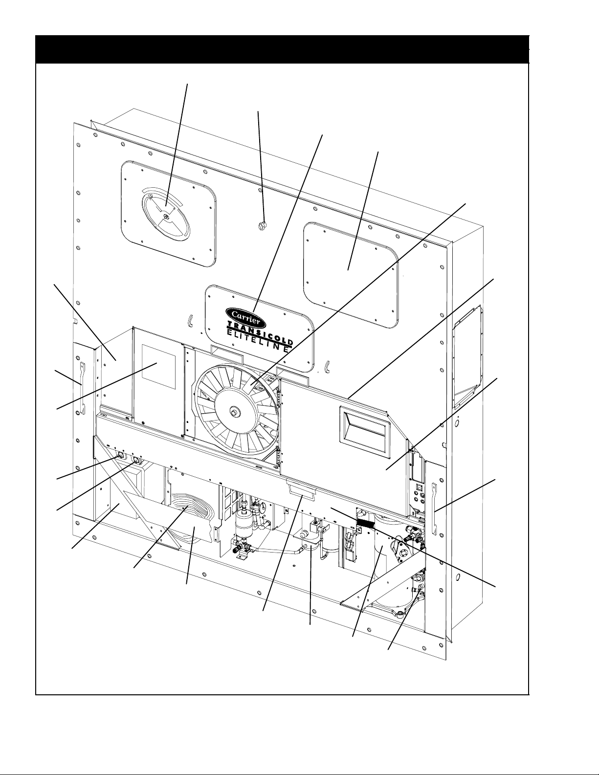
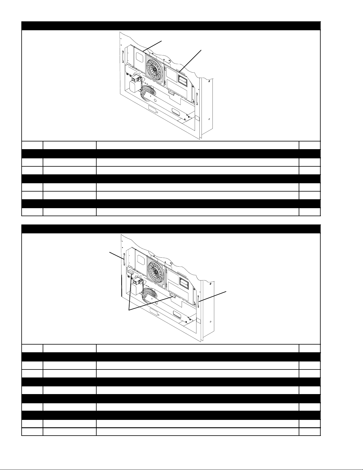
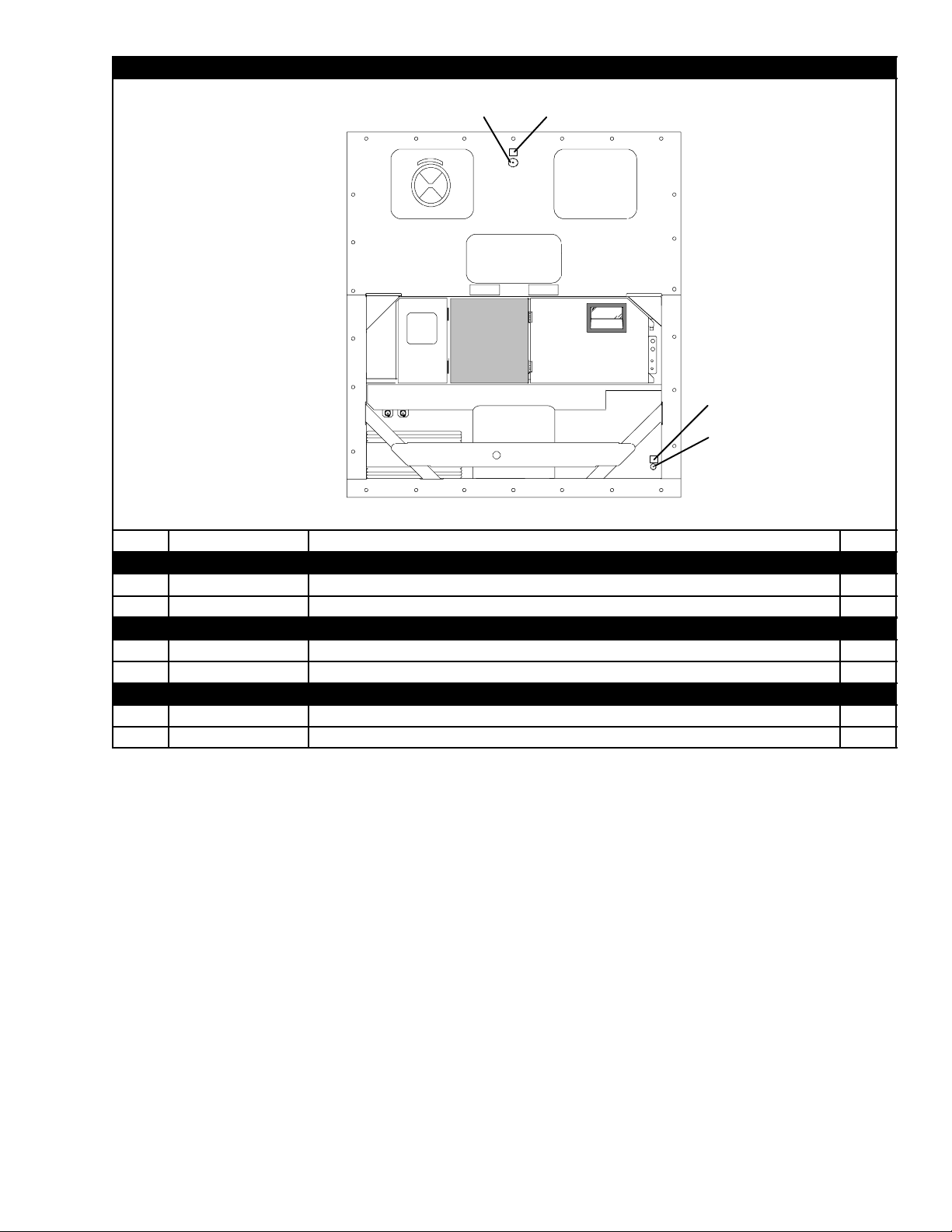
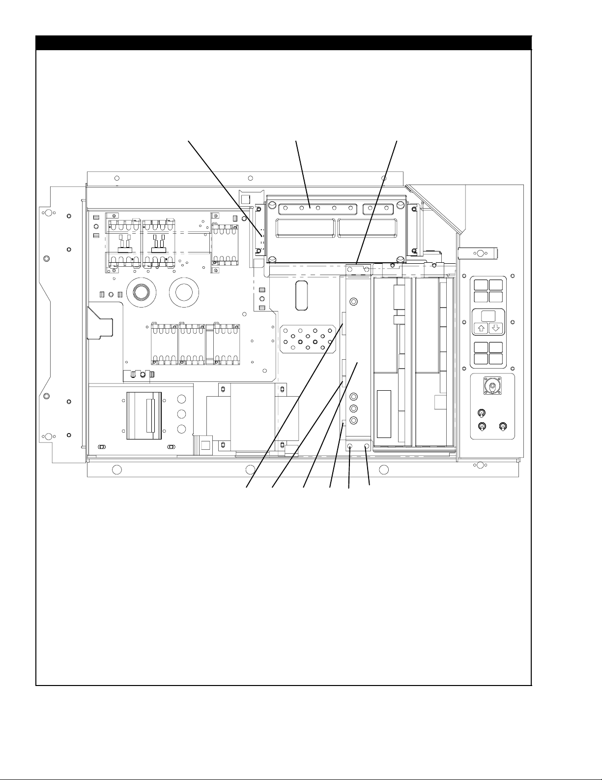
2 REFRIGERATION UNIT ASSEMBLY
2.1 REFRIGERATION UNIT -- AREA LOCATOR
1
2
3
4
5
19
18
17
16
6
8
15
7
8
13
14
12
9
8
10
11
2
2T-292PL
Page 12

2.1 REFRIGERATION UNIT -- AREA LOCATOR
Item Section Number Area Description
1 Refer to Section 2.17 Upper Fresh Air Makeup & Access Panels
2 Refer to Section 2.4 Thermometer Port
3 Refer to Section 2.35 Labels and Decals
4 Refer to Section 2.19 Evaporator Fan Assembly
5 Refer to Section 2.10 Motor, Condenser Fan
6 Refer to Section 2.2 Rain Gutters
7 Refer to Section 2.5 -- 2.9 Box, Control
8 Refer to Section 2.3 Handles
9 Refer to Section 2.10 Coil, Condenser
10 Refer to Section 2.12 or 2.13 Receiver or Water-Cooled Condenser
11 Refer to Sections 2.30 or 4 Compressor
12 Refer to Section 2.30 Guard, Compressor
13 Refer to Section 2.33 Cable, Power
14 Refer to Section 2.33 Plug, Power
15 Refer to Section 2.34 Autotransformer
16 Refer to Section 2.19 Transfresh
17 Refer to Section 3 Interrogator and Accessories
18 Refer to Section 2.26 -- 2.29 Temperature Recorder
19 Refer to Section 2.18 Lower Fresh Air Makeup
3 T-292PL
Page 13
2.2 RAIN GUTTERS
2
or
4
Item Part Number Description Qty
OPTION 1 -- STANDARD LENGTH -- BOLTED
1 69NT35-3987 Gutter, Rain (Bolted, Standard -- Right Side) 1
2 69NT35-3997-1 Gutter, Rain (Bolted, Standard & Extended Length -- Left Side) 1
OPTION 3 -- EXTENDED LENGTH -- BOLTED
2 69NT35-3997-1 Gutter, Rain (Bolted, Standard & Extended Length -- Left Side) 1
3 69NT35-8548 Gutter, Rain (Bolted -- Right Side) 1
OPTION 4 -- RIVETED
4 68-12417-00 Gutter, Rain (Riveted -- Right and Left Side) 2
1
or
3
or
4
2.3 HANDLES
1
1
2
Item Part Number Description Qty
OPTION 1 -- TWO SIDE, ONE CENTER
1 69NT35-8113 Handle, Fixed 2
2 69NT40-657-2 Handle, Hinged 1
OPTION 2 -- TWO SIDE
1 69NT35-8113 Handle, Fixed 2
OPTION 3 -- ONE CENTER
2 69NT40-657-2 Handle, Hinged 1
OPTION 4 -- ONE SIDE, TWO CENTER
1 69NT35-8113 Handle, Fixed 1
2 69NT40-657-2 Handle, Hinged 2
4T-292PL
Page 14
2.4 THERMOMETER PORT
3
Item Part Number Description Qty
OPTION 1 -- SUPPLY AIR PORT
1 66U1-8662 Cap & Chain Assembly 1
2 62-10557-00 Label 1
OPTION 2 -- RETURN AIR PORT
3 66U1-8662 Cap & Chain Assembly 1
4 62-10557-00 Label 1
OPTION B -- SUPPLY AND RETURN PORTS
1&3 66U1-8662 Cap & Chain Assembly 2
2&4 62-10557-00 Label 2
4
2
1
5 T-292PL
Page 15
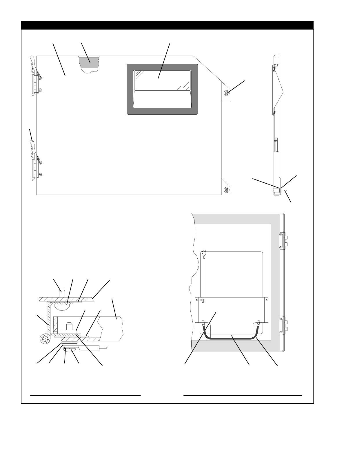
2.5 CONTROL BOX DOOR
12 3
9
4
5
6
8
20 21
10
11 12
Control Box
Control Box Door
6
4
5
16
HINGE ASSEMBLY -- SECTIONAL VIEW DOOR ASSEMBLY -- PARTIAL BACK VIEW
15
14
13
7
17
6T-292PL
18
14
15
19
22
Page 16

2.5 CONTROL BOX DOOR
Item Part Number Description Qty
1 69NT42-688-7 Door Assembly -- Includes: 1
2 42-00270-02 Gasket, Door 1
3 58-04366-00SV Window and Gasket Assembly, Control Box Door -- Lexan 1
4 34-06169-00 Washer, Retaining -- SST 2
5 66U1-6811-8 Screw , Retaining, Panel, 0.300-0.625 -- SST 2
5 66U1-6811-15 Screw, Retaining, Wing, 0.300-0.625 -- SST 2
6 34-06053-00 Washer, Mylar, 0.250 ID x 0.800 OD 4
7 44-00300-01 Hinge, Half 1
8 44-00300-02 Hinge, Half 1
9 44-00300-03 Pin Assembly, with Tether 1
10 58-04101-01 Protector, Mylar (Hinge) (Not Needed with Composite Box) 2
11 34-01167-01 Retainer, Nut 2
12 58-04101-00 Protector, Mylar (Hinge) 2
13 66U1-2403-1 Screw, Truss Head, #10-24 x 3/4 lg. -- SST 4
14 66U1-5331-3 Washer, Lock, #10 -- SST 7
15 66U1-5321-8 Washer, Flat, #10 -- SST 7
16 34-06053-05 Washer, Mylar, 0.205 ID x 0.600 OD 4
17 68-13577-00 Pocket, Placard 1
18 34-00665-09 Locknut, Hex Head, #10-24 -- SST 3
19 34-06107-00 Rivet, Blind, 1/8 Diameter, Grip Range -- 0.188-0.250 3
20 66U1-5371-7 Screw, #10-24 x 1/2 lg. -- SST 4
21 66U1-5321-8 Washer, Flat, #10 -- SST 4
22 58-04346-00 Door Strap Kit 1
7 T-292PL
Page 17
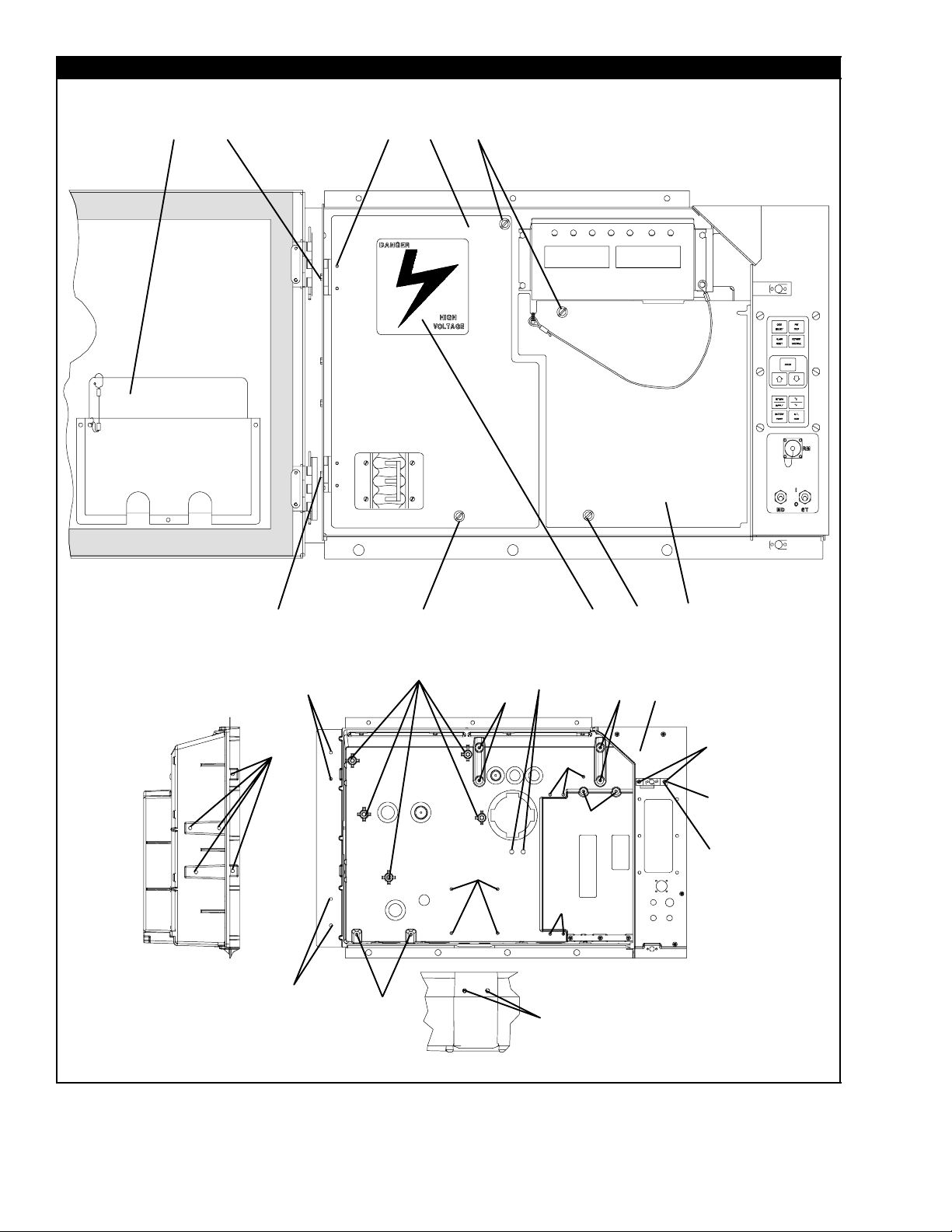
2.6 CONTROL BOX
4
1
2
3
5
6
7
2
18
20
6
7
20
OPTIONC&CL--COMPOSITEBOX
15
17
16
16
19
18
16
16
17
10
8
In Box
16
11
12
13
14
9
6
7
17
8T-292PL
Page 18

2.6 CONTROL BOX (Continued)
Item Part Number Description Qty
1 -- Plate, Schematic & Diagram (Refer to T-300, Container Unit Matrix) 1
2 66U1-2403 Screw , Truss Head, #10-24 x 1/2 lg. -- SST 2
3 69NT43-125-1 Shield, High Voltage (Plastic) -- Includes: 1
4 44-00343-00 Hinge 2
5 34-00928-02 Rivet, Blind, 1/8 Diameter, Grip Range -- 1/8-3/16 -- SST 4
6 34-50015-00 Stud & Retainer Package -- Includes: 4
NS NSS Stud, Fastener 1
NS NSS Retainer, Fastener Stud 1
7 34-06139-03 Receptacle 4
8 69NT43-124-4 Shield, Low Voltage (Lexan) -- With Tether 1
9 62-03957-01 Label, Danger-High Voltage 1
58-04367-02 Control Box, Standard Composite (Blue) 1
58-04367-05 Control Box, Standard Composite (Orange) 1
10
58-04367-07 Control Box, Standard Composite w/EBS (Orange) 1
58-04367-08 Control Box, Standard Composite W/EBS (Blue) 1
69NT35-6272 Bracket, Non--Locking 1
11
69NT35-2287 Bracket, Locking (See Note 3) 1
12 34-01142-01 Receptacle, Retaining 1
34-00928-01 Rivet, Blind, 1/8 Diameter, Grip Range -- 1/16 - 1/8 2
13
34-00928-02 Rivet, Blind, 1/8 Diameter, Grip Range -- 1/18 - 3/16 (See Note 4) 2
14 66U1-2403 Screw, Truss Head, #10-24 x 1/2 lg. -- SST 2
NS 76-00724-00SV Crack, Chip and Hole Repair Kit 1
NS 76-50084-00SV Insert Repair Kit -- Includes: 1
15 34-06231-01 Insert -- 17.53 x 9.91 mm (.690 x .390 in) 1/4-20 Threads -- NSS 10
16 34-06231-03 Insert -- 15.88 x 6.35 mm (.625 x .250 in) 10-24 Threads -- NSS 10
17 34-06231-04 Insert -- 25.15 x 7.54 mm (.990 x .297 in) 10-24 Threads -- NSS 10
18 34-06231-05 Insert -- 10.16 x 9.53 mm (.400 x .375 in) 10-24 Threads -- NSS 10
19 34-06231-06 Insert -- 12.70 x 9.91 mm (.500 x .390 in) 1/4-20 Threads -- NSS 10
20 34-06231-07 Insert -- 9.53 x 6.76 mm (.375 x .266 in) 10-24Threads -- NSS 10
NS 02-00082-00 Durabond Epoxy -- NSS 1
NS 07-00390-00 Static Mixing Tube -- NSS 1
NS 07-00391-00 Application Gun -- Required for Insert Repair 1
NOTES
3. The bracket is bolted to the control box -- order 69NT35-2287 for locking bracket.
4. When 69NT35-2287 is used, 34-00928-02, rivet, is to be used in the upper door location.
9 T-292PL
Page 19
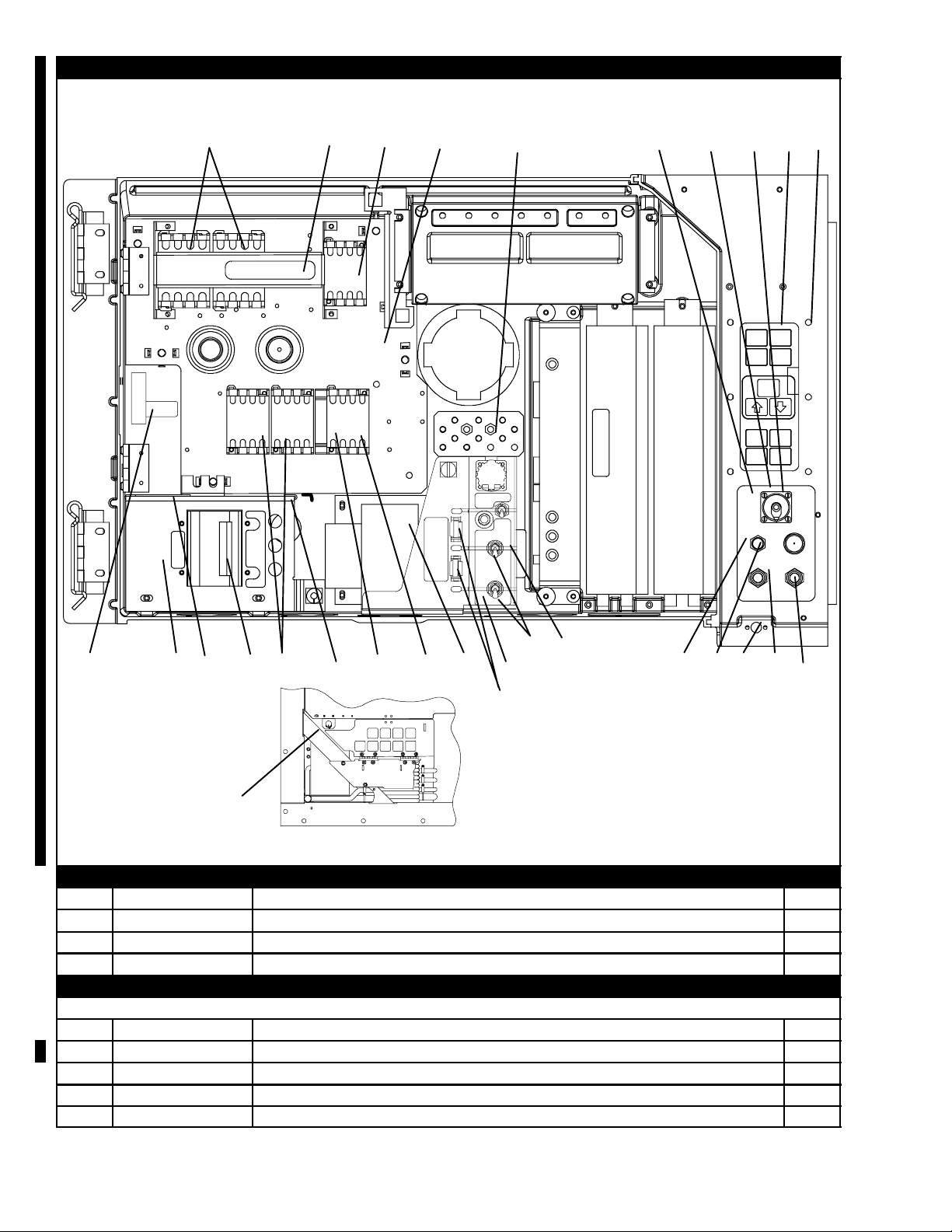
2.7 CONTROL BOX -- SHIELDS REMOVED, STD ELECTRICAL COMPONENTS, RM , CFS, EBS AND ED
28
4
5
34
35
36
5
6
7
8
9
16
44
41
42
43
37
38
39
40
29
30
31
32
33
50
19
25
26
18
19
24
27
21
22
23
12
48
47
13
5
6
27
20
17
5
18
6
19
15
1
2
3
10
11
13
14
12
13
49
45
46
REMOTE MONITORING --LOWER/EXTERNAL MTG
OPTION F -- CONDENSER FAN SWITCH
Item Part Number Description Qty
1 10-00298-01 Switch, Toggle (CFS) 1
2 66U1-9752 Seal, Bushing 1
58-04145-06 Plate, Switch (with extra switch location) 1
3
OPTION 1 -- NORMAL EVAPORATOR FAN OPERATION
See Items 5 and 6 for correct contactor placement
10-00431-07 Contactor, Compressor (CH) (30 Amp) 2
4
34-06243--00 Screw, Hex Head w/ Washer, #8-32 x 5/8 lg. -- SST 12
5
10-00431--06 Contactors, (CF), (HR) & (EF & ES) (12 Amp) 4
6
68-13427-00SV Panel, Contactor -- Includes: 1
7
58-00967-00 Spacer (Used with sheet metal control box only) 5
8
10T-292PL
Page 20

2.7 CONTROL BOX -- SHIELDS REMOVED, STANDARD ELECTRICAL COMPONENTS (Continued)
Item Part Number Description Qty
34-06224-01 Screw, Hex Head, Captive Washer 1/4-20 x .62 lg. -- SST 4
9
34-00928-01 Rivet, Blind, 1/8 Diameter, Grip Range -- 1/16 - 1/8 6
10
34-01142-01 Receptacle 1
11
10-01129-07 Switch, T oggle (On-Off) 1
12
66U1-9752 Seal, Bushing 2
13
10-01129-10 Switch, T oggle (MDS) 1
14
58-04145-01 Plate, Switch 1
15
69NT41-982-3 Plate, Ground 1
16
10-00332-21SV Transformer, Base Unit 1
17
66U1-5371-7 Screw, Hex Head, #10-24 x 1/2 lg. -- SST A/R
18
66U1-5321-8 Washer, Flat, #10 -- SST A/R
19
10-00431--02 Contact, Auxiliary 1
20
34-00663-07 Washer, Lock, #6 -- SST 4
21
66U1-7842-13 Circuit Breaker -- 460 vac, 25 Amp, (CB1) 1
22
66U1-6651-4 Screw, Pan Head, #6-32 x 3/8 lg. -- SST 4
23
69NT35-6278 Bracket, Circuit Breaker 1
24
10--00439--01 Transformer, Current Sensing (CS) 1
25
34-06223-00 Screw, Captive Washer, #10-24 x .56 lg. -- SST 2
26
66CH1-1172-46 Trim, Flexible (85 Feet Long, Cut to Length) A/R
27
28 79--66669--00 Pad, Key -- Includes: 1
29 NSS Dot, Indicator (Green) -- See Note 1
30 NSS Gasket (Between Key Pad and Key Pad Plate Assembly) 1
31 NSS Plate Assembly , Key Pad Mounting 1
32 34--66630--00 Screw, Pan Head, #10--24 X 3/4 Long -- SST 6
33 34--06212--10 Washer, Plain, #10 6
58-04260-00 Cover, Clear 1
34
35 66U1-5391-2 Screw, Pan Head (Thread Cutting), #8-32 x 1/2 lg. -- SST 4
36 34-00662-08 Washer, Plain, #8 4
REMOTE MONITORING (STANDARD LOCATION)
22-02341-00 Receptacle, Remote Monitoring (RM) 1
37
22-02368-00 Plug, Remote Monitoring 1
38
22-02341-01 Cap and Tether, Receptacle Assembly 1
39
66U1-6835 Gasket, Remote Monitoring Receptacle 1
40
34-00848-10 Screw, Round Head, #4-40 x 5/8 lg. -- SST 4
41
66U1-5321-6 Washer, Flat, 0.125 ID -- SST 4
42
34-00667-05 Nut, Self Locking, #4-40 -- SST 4
43
58-04145-00 Plate, Switch, with RM 1
44
REMOTE MONITORING (LOWER LEFT/EXTERNAL LOCATION)
22-01889-00 Receptacle, Remote Monitoring (RM) 1
45
69NT40-222 Bracket 1
46
EMERGENCY BYPASS & EMERGENCY DEFROST
10--00446--00 Emergency Bypass Module 1
47
22--02336--04 Fuse (10A) 2
48
22--01455--03 Fuse Holder 2
49
66U1--5371--10 Wire Tire 3
50
Change 01/10
11
T-292PL
Page 21
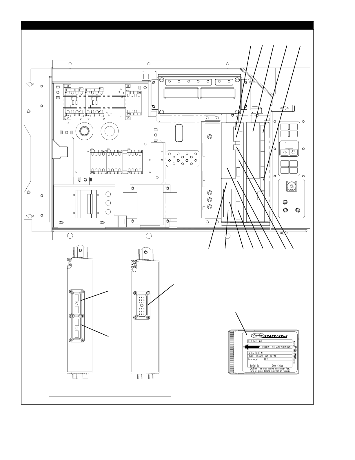
2.8 CONTROL BOX -- CONTROLLER MODULE SECTION AND SOFTWARE CARDS
16 17
19
22
21
9
10
11
12
13
10
12
View -- Back of Controller/DataCORDER and
Expansion Modules
10
12
20
1
2
3
4
24
25
23
8
1415
5
7
18
6
12T-292PL
Page 22

2.8 CONTROL BOX -- CONTROLLER MODULE SECTION AND SOFTWARE CARDS
Item Part Number Description Qty
1 -- Module, Controller/DataCORDER -- RefertoSection5-- Includes: --
2 66U1-5371-7 Screw , Hex Head, #10-24 x 1/2 lg. -- SST 1
3 69NT35-2692 Washer, Fender, 0.063 Thick -- SST 1
4 58-01184-00 Retainer, Screw, 0.141 ID 1
5 22-02336-04 Fuse, 10 Amp (F3) 3
6 22-02336-02 Fuse, 5 Amp (F1 & F2) 1
7 62-02719-00 Label, Controller/DataCORDER Port 1
8 12-00397-00/5311 Card, Controller/DataCORDER Operation Software 1
NS 12-00402-xx Card, Configuration Software 1
9 22-01777-00SV Connector (EC A-K) -- 30 Pin 1
10 22-01777-03 Socket, 20 AWG 35
11 22-50100-00 Socket, 18 AWG 4
12 22-01777-04 Plug, Sealing 21
13 22-01777-01SV Connector (EC L-Y) -- 30 Pin 1
14 22-01556-02 Connector (KA) -- 14 Pin 1
15 22-01556-01 Connector (KB) -- 10 Pin 1
NS 22-01621-23 Connector (KP) -- 9 Pin (Connects to Ribbon Cable) 1
16 22-01622-01 Connector (MA) -- 12 Pin 1
17 22-01622-02 Connector (MB) -- 16 Pin 1
18 22-01622-00 Connector (MC) -- 8 Pin 1
19 12-55535--10 Module, Controller Expansion 1
20 22-01777-05 Connector (EE A-K) -- 30 Pin 1
21 22-01556-06 Connector (KE) -- 7 Pin 1
22 22-01556-07 Connector (KR) -- 8 Pin 1
NS 09-00369-00SV Battery, Real Time Clock, (Within the Controller) 1
NS 22-50157-00 Wire Harness, Controller to Current Sensing Transformer) 1
NS 22-01713-06 Wire Harness, Display Module to Controller/DataCORDER Module 1
NS 62-02735-00 Label, Warning, Don’t use 12-00327 ! --(Located on the control box behind
the Controller/DataCORDER module.)
NS 62-02738-08 Label, Warning, 53xx Series -- (Located on the high & low voltage shields) 1
NS 62-02738-04 Label, Warning, 53xx Series -- (Located on the bottom panel of the control
box between the Communications Interface module and the switch panel.)
OPTION R -- RECHARGEABLE BATTERY PACK
23 30-00407-02SV Battery Pack -- Controller/DataCORDER Module 1
OPTION S -- STANDARD CELLS
24 PL Battery (”AA”) 6
25 30-00407-00 Cover, Controller Battery 1
1
1
13 T-292PL
Page 23
2.9 CONTROL BOX -- DISPLAY MODULE AND COMMUNICATIONS INTERFACE MODULE SECTION
1
34
2
56
14T-292PL
78
11
11
9
10
Page 24

2.9 CONTROL BOX -- DISPLAY MODULE AND COMMUNICATIONS INTERFACE MODULE SECTION
Item Part Number Description Qty
1 12-00433-00RP Module, Display 1
2 34--06223--01 Screw, Hex Head, #10-24 x 1/2 lg. w/Captive Washer 0.063 Thick -- SST 4
3 22-01621-03 Connector (MK) -- 9 Pin 1
4 22-01621-02 Connector (MB) -- 16 Pin 1
5 22-01556--06 Connector (CIC) -- 7 Pin 1
6 22-01556--04 Connector (CIB) -- 3 Pin 1
7 22-01556-00 Connector (CIA) -- 7 Pin 1
NS 22-01713-02 Wire Harness, Key Pad to Display Module 1
OPTION 1 -- COMMUNICATIONS INTERFACE MODULE -- STANDARD
8 12-00275-04SV Module, Communications Interface -- Includes: 1
9 34-06223-00 Screw, Captive Washer #10-24 x 0.56 -- SST 2
10 34-06223-01 Screw, Captive Washer #10-24 x 0.56 -- SST 2
11 58-01184-00 Retainer, Screw .75 O.D. 4
OPTION 2 -- COMMUNICATIONS INTERFACE MODULE -- HIGH DATA RATE
8 12-00275-10SV Module, Communications Interface -- Includes: 1
9 34-06223-00 Screw, Captive Washer #10-24 x 0.56 -- SST 2
10 34-06223-00 Screw, Captive Washer #10-24 x 0.56 -- SST 4
11 58-01184-00 Retainer, Screw .75 O.D. 4
OPTION 3 -- COMMUNICATIONS INTERFACE MODULE -- CHIPSET MODEM
8 12-00275-17SV Module, Communications Interface -- Includes: 1
9 34-06223-00 Screw, Captive Washer #10-24 x 0.56 -- SST 2
10 34-06223-00 Screw, Captive Washer #10-24 x 0.56 -- SST 4
11 58-01184-00 Retainer, Screw .75 O.D. 4
OPTION 4 -- COMMUNICATIONS INTERFACE MODULE -- LOW DATA RATE
8 12-00275-19SV Module, Communications Interface -- Includes: 1
9 34-06223-00 Screw, Captive Washer #10-24 x 0.56 -- SST 2
10 34-06223-00 Screw, Captive Washer #10-24 x 0.56 -- SST 4
11 58-01184-00 Retainer, Screw .75 O.D. 4
15 T-292PL
Page 25
2.10 CONDENSER FAN MOTOR AND CONDENSER COIL SECTION
1
2
3
4
6
14
12
13
15
19
OPTION 4 OR OPTION 5
18
20
21
22
23
24
Item Part Number Description Qty
1 66U1-5361-25 Capscrew, Hex Head, 1/4-20 x 3/4 lg. -- SST 10
2 66U1-5321-7 W asher, Flat, 1/4 -- SST 10
3 34-06053-00 Washer, Mylar, 3/4 OD x 1/4 ID 10
4 34-06053-03 Washer, Mylar, 1.0 OD x 1/4 ID 2
5 22--04018--00SV Pigtail Connector 1
6 54--00586--00 Bracket, Condenser Motor Mount 1
7 54-00549-00 Motor, Condenser Fan -- Includes: 1
8 PL Key, 3/16 Square x 1-3/8 lg. -- SST 1
9 04-50027-00 Bearing 2
10 22-50088-02 Capacitor, 15 uF 1
11 66U1-5361 Screw, Hex Head, 5/16-18 x 1-1/4 lg. -- SST 4
12 34-01181-01 Washer, Flat, 5/16 -- SST 8
13 34-06053-02 Washer, Mylar, 1.0 OD x 3/8 ID 4
14 34-00667-12 Locknut, 5/16-18 -- SST 4
15 69NT35-6112 Protector, Condenser Fan Motor Mounting 2
16 38-00503-00 Fan, Condenser (17-1/2 diameter) -- Composite -- Includes: 1
17 PL Set Screw,Square Head, 5/16-24 x 5/8 lg. -- SST 2
25
26
28
29
30
33
34
35
36
31
17
16
32
37
38
39
40
OR
41
42
43
44
12
11
5
8
7
9
10
16T-292PL
Page 26

2.10 CONDENSER FAN MOTOR AND CONDENSER COIL SECTION (Continued)
Item Part Number Description Qty
OPTION 4 -- FOUR ROW (7MM) CONDENSER COIL
68-14546-02SV Cover, Condenser Coil, Blue Includes: 1
18
68-14546-03SV Cover, Condenser Coil, White Includes: 1
19 58-04481-00 Plug (for use with coated handle or units with no center handle) 2
20 81-01855-00SV Coil, Condenser(Copper) -- 7MM 4 Row -- Includes Mylar Washers 1
21 66CH1-1172-16 Trim, Flexible 2
22 69NT35-8693-8 Protector (Apply between frame and coil & coil cover) 4
23 69NT35-8693-9 Protector (Apply between frame and coil & coil cover) 2
24 58-04026-41 Protector,Mylar (Apply between coil & coil cover, RH &LH sides) 2
OPTION 5 -- FIVE ROW (3/8”) CONDENSER COIL
68-12757-00 Cover, Condenser Coil, Blue Includes: 1
25
68-12757-01 Cover, Condenser Coil, White Includes: 1
19 58-04481-00 Plug (for use with coated handle or units with no center handle) 2
26 81-01490-00SV Coil, Condenser(Copper) -- 5 row -- Includes Mylar Washers 1
27 66CH1-1172-16 Trim, Flexible 2
28 69NT35-8693-5 Protector (Apply between frame and coil & coil cover) 4
29 69NT35-8693-6 Protector (Apply between frame and coil & coil cover) 4
30 58-04026-10 Protector,Mylar (Apply between coil & coil cover, RH &LH sides) 2
OPTION H -- HINGED CONDENSER FAN GRILLE
31 76-00704-01 Grille and Venturi Assembly, Blue -- Includes: 1
31 76-00704-02 Grille and Venturi Assembly, White -- Includes: 1
32 66U1-8912 Label, Rotation 1
33 76-50075-00 Hinge Kit -- Includes: 1
34 44-00374-00 Hinge 2
35 58-04101-07 Protector, Mylar 4
36 34-06179-00 Screw, Hex Head, #10-24 x 7/16 lg. -- SST 8
66U1-6811-8 Screw, Retaining -- SST 2
37
66U1-6811-12 Screw, Retaining (Phillips Head) -- SST 2
38 34-06169-00 Washer, Retaining -- SST 2
39 34-06053-03 Washer, Mylar, 1/4ID x 1.00OD 2
40 69NT35-2692-1 Washer, Fender 1/4 -- SST 2
OPTION B -- BOLTED CONDENSER FAN GRILLE
31 76-00704-01 Grille and Venturi Assembly, Blue -- Includes: 1
31 76-00704-02 Grille and Venturi Assembly, White -- Includes: 1
32 66U1-8912 Label, Rotation 1
41 69NT35-2692-1 Washer, Fender 1/4 -- SST 4
42 34-06053-03 Washer, Mylar, 1/4ID x 1.00OD 4
43 34-00663-11 Washer, Lock, 1/4 -- SST 4
44 66U1-5361-25 Capscrew, Hex Head, 1/4-20 x 3/4 lg. -- SST 4
17 T-292PL
Page 27

2.11 COMPRESSOR TUBING SECTION
1,8,9
1,7,9
1,2,9
12
3,13,16
14,15
11,13,17
4,5
3,10,13,18
4,5
26
13,19
4,5
6
1,8,9
20,21
1,7,9
Units with Standard Tubing
1,2,9
12
12
3,10,24
11,22
4,5
3,10,23
4,5
26
25
6
T-292PL
Units with Semi--Hermetic Tubing
18
Change 07/04
Page 28

2.11 COMPRESSOR TUBING SECTION
Item Part Number Description Qty
Common Components
1 34-06053-00 Washer, Mylar, .25 I.D. x .80 O.D. 4
2 34-00373-07 Clamp, Cushion, .62 Dia. 1
3 42-00384-02 Seal 1 1/4” Thread (See Section 4) 2
4 40--00542-00 Elbow, Adapter, Brass A/R
5 40-00520-02 Cap, M8 x 1.0 -- Nylon A/R
6 40-00586-00 Coupling, Oil Return 1
7 66U1-3632-20 Clamp, Cushion, .88 Dia. 2
8 34-00373-53 Clamp, Cushion, .38 Dia. 1
9 66U1-5371-6 Screw, Hex Head, #10-24 x .75 lg. -- SST 4
10 14-00176-04 Strainer 1
11 42-00384-01 Seal 1” Thread (See Section 4) 1
12 58--04026--26 Tubing Protector 1
Standard Tubing Components
13 40-50025-00 Cap, Service Valve 4
14 40-00542-01 Elbow, Adapter, High Pressure, R134a -- Brass 1
15 40-00520-03 Cap, M10 x 1.0 -- Nylon 1
16 40-00583-00 Valve, Service 7/8 I.D. (11/4” Thread) 1
17 40-00583-01 Valve, Service 5/8 I.D. (1” Thread) 1
18 40-00583-03 Valve, Service 1 1/8 I.D. (11/4” Thread) 1
19 40-00585-00 Valve, Service 3/8 I.D. 1
Semi--Hermetic Tubing Components
20 66U1--3882--3 Wire Tie 2
21 58--00850--21 Tube, Slit 1
22 40--00605--03 Economizer Tubing Assembly with Fitting (1” Thread) 1
23 81--01807--01 Suction Tubing Assembly with Fitting (11/4” Thread) 1
24 58--04026--26 Discharge Tubing Assembly with Service Fitting (11/4” Thread) 1
25 81--01808--01 Oil Return Tubing Assembly with Fitting 1
REFRIGERATION TEMPERATURE SENSORS
26 12-00493-05 Sensor, Thermistor (CPDS) 1
-- -- Sensor, Thermistor (CPSS) See Section 2.20 1
Change 07/04
19
T-292PL
Page 29

2.12 RECEIVER SECTION
5
6
7
1
8
4
Item Part Number Description Qty
STANDARD RECEIVER -- USE OPTION L AND SUBSTITUTE ITEM BELOW FOR 79--01785--01
NS 79-01785-00 Receiver Assembly 1
OPTION L
1 79-01785-01 Large Receiver Assembly -- Includes: 1
2 14-00220-01 Glass, Sight 1
3 14-00221-01 Indicator, Moisture-Liquid 1
4 14-01032-14 Plug, Fusible, 3/8 npt -- Brass 1
5 58-04026-61 Protector, Mylar 2
6 66U1-5361-25 Screw, Hex Head, 1/4-20 x 3/4 lg. -- SST 4
7 66U1-5321-7 W asher, Flat, 1/4 -- SST 4
8 34--06035--00 Washer , Mylar 4
9 12-00495-20 Sensor, Ambient Thermistor (AMBS) 1
10 -- See Section 2.15 for Sensor Assembly and Related Parts --
23
910
20T-292PL
Page 30

2.13 WATER--COOLED CONDENSER SECTION
18
20
20
23
21
22
24
25
5
4
10
11
16
1
9
17
6
2
7
13
8
25
3
19
20
21
15
14
Item Part Number Description Qty
-- 76-00734-00 Kit, Condenser/Receiver (For Field Installation) -- Includes: 1
1 69NT42-954-4 Condenser/Receiver -- Includes: 1
2 14-00220-01 Sight Glass, w/red balls, 1/2 npt 1
3 58-00956-00 Protector, Mylar 2
4 58-04436-00 Protector, Mylar 1
5 66U1-2763-5 Coupling (Water-In) 1
6 66U2-1142 Cap, Dust 1
7 40-01129-00 Coupling, Self Draining -- Includes: 1
8 42-50000-00 Seal, O-Ring 1
9 66U2-1152 Cap, Dust 1
10 12-01071-01SV Switch,Water Pressure OPTION W 1
11 66U2-1132-1 Connector 2
12 66U1-3803 Heat Shrink 2
13 14-00215-05 Disc, Rupture, 3/8 npt 1
14 12-00495-20 Sensor, Ambient Thermistor (AMBS) 1
15 -- See Section 2.15 for Sensor Assembly and Related Parts -16 14-01092-03 Indicator, Liquid Moisture -- Brass 1
17 40-01129-00 Tee, 1/2 X 1/2 X 3/8 NPT -- Brass 1
18 68-13852-00 Bracket (Style 1) 1
19 68--14102--00 Bracket (Style 2)
20 66U1-5371-6 Screw, Hex Head, #10-24 x 3/4 lg. -- SST 3
21 69NT35-2692 Washer, Fender 1
22 34-00667-09 Nut, Self-Lock, #10-24 -- SST 1
23 34-06053-05 Washer, Mylar, .205 I.D. x .60 O.D. 3
24 66U1-5321-8 Washer, Plain, #10 -- SST 3
25 34-00373-05 Clamp, Cushion, 1/2 Diameter 1
21 T-292PL
Page 31

2.14 ECONOMIZER, ECONOMIZER EXPANSION VALVE, ECONOMIZER SOLENOID VALVE AND
FILTER DRIER SECTION
Item Part Number Description Qty
1 68-12864-00 Cover 1
2 34-06053-00 Washer, Mylar, 0.250 ID x 0.800 OD 18
3 66U1-5361-25 Screw, Hex Head, 1/4-20 x .75 lg. -- SST 13
4 66U1-5321-7 W asher, Flat, 1/4 -- SST 13
5 34-00667-11 Nut, Self-Lock 2
6 40-00520-01 Coupling with Cap 1
7 14-00311--02SV Filter-Drier -- Includes: 1
8 14-00284-20SV O-Ring 2
9 34-00373-54 Clamp, Cushion, .44 Diameter 1
10 34-06053-05 Washer, Mylar, .205 I.D. x .60 O.D. 9
11 66U1-5371-7 Screw, Machine, Hex Head, #10-24 x .50 lg. -- SST 1
12 68-13479-00 Bracket 1
13 66U1-5321-8 Washer, Plain #10 -- SST 4
14 66U2-1132-2 Connector 4
15 66U1-3803 Heat Shrink 6
16 14-01091-01 Coil, Solenoid Valve (Oil Return and Economizer) 1
17 DE40BA203 Tee, Reducing 1/2 x 1/2 x 3/8 1
18 34-00373-05 Clamp, Cushion, .50 Diameter 1
19 68-12863-00 Bracket 1
20 68-13167-00 Bracket 1
21 42-00389-00 Insulation, Economizer 1
22 40-00168-05 Tee 1
23 68-13784-00 Bracket 1
24 66U1-5321-3 Washer, Plain, 1/4 N Type A -- SST 2
25 68-13785-00 Bracket 1
26 66U1-5371 Screw, Machine, Hex Head, #8-32 x .50 lg. -- SST 4
27 66U1-5321-2 Washer, Plain #8 -- SST 4
28 66U1-5331-4 Washer, Lock, #8 Spring -- SST 4
29 69NT35-2692-1 Washer, Fender 1
30 14-01091-02 Coil, Solenoid Valve 1
31 14-01090-11 Solenoid Valve Body 1
32 81-01539-20 Economizer 1
33 58--00836--19 Bushing 2
34 69NT35-2692-4 Washer, Fender #10 -- SST 1
35 14-01090-10 Solenoid Valve Body 1
36 14-00232-08 Expansion Valve 1
37 34-00373-07 Clamp, Cushion, .62 Diameter 1
38 14-00222-01 Valve, King 1
39 68--14103--00 Bracket, Blue 1
39 68--14103--20 Bracket, White 1
40 42-00390-00 Insulation, Economizer 1
41 42--00174--44 Gasket, 2.0 x 2.0 1
42 69NP20--1031 Clamp, Tube, 2.88 diameter 1
43 66U1--5371--6 Screw, Machine, Hex Head, #10--24 x .75 lg.-- SST 6
44 68--10694--00 Plate 1
23 T-292PL
Page 32

2.15 SRS AND STS SECTION
2
3
2
3
1
(STS)
1
(SRS)
45
Item Part Number Description Qty
1 12-00395-01SV Sensor Assembly (STS & SRS) 1
2 58-04277-00SV Cap, Probe -- Includes: 2
3 58-04278-00 Grommet NSS 2
4 58-04279-00 Cover, Probe 1
5 58-04276-00 Holder, Probe 1
6 66U1-5321-7 W asher, Flat, 1/4 -- SST 2
7 66U1-5371-7 Screw, Machine, Hex Head, #10-24 x .50 lg. -- SST 2
24T-292PL
6
7
Page 33

2.16 OIL SEPARATOR SECTION
6
1
2
3
4
7
1011
12
13
Item Part Number Description Qty
1 34-06053-00 Washer, Mylar, 0.250 ID x 0.800 OD 4
2 66U1-5361-25 Screw, Hex Head, 1/4-20 x .75 lg. -- SST 4
3 66U1-5321-7 W asher, Flat, 1/4 -- SST 4
4 58-04026-34 Protector, Mylar 2
5 65-00180-20SV Oil Separator Includes: 1
6 56--07525--00 Tubing 1
7 66U1-5371 Screw , Machine, Hex Head, #8-32 x .50 lg. -- SST 2
8 66U1-5321-2 W asher, Plain #8 -- SST 2
9 66U1-5331-4 W asher, Lock, #8 Spring -- SST 2
10 14-00285-00 Solenoid Valve 1
11 66U2-1132-2 Connector 2
12 66U1-3803 Heat Shrink 2
13 14-01091-01 Coil, Solenoid Valve 1
5
8
9
25 T-292PL
Page 34

2.17 UPPER FRESH AIR MAKE-UP AND ACCESS PANEL SECTION
7
2
23
22
21
8
5
4
6
3
17
16
9
18
19
FRESH AIR PANEL
WITH VPS
12
11
BACK OF FRESH
AIR PANEL
10
20
14
13
6
2.17 UPPER FRESH AIR MAKE-UP AND ACCESS PANEL SECTION
Item Part Number Description Qty
OPTION 1 EVAPORAT OR FAN ACCESS PANEL -- PLAIN
1 79-01697-06SV Panel, Access (See NOTE 1) -- Includes: A/R
2 42-00296-01 Gasket 1
3 42-00327-00 Gasket, -- 0.26 x 0.50 Halfmoon 1
4 34-006212--12 Washer, Flat, 1/4 -- SST 8
5 34-06053--13 Washer, Mylar, 1/4 ID X 0.80 OD 8
6 34-06154-00 Screw, Hex Head, 1/4-20 x 1.00 lg. -- TIR 8
7 66U1-2552-185 Gasket, 0.75 x 1.5 x 16.63 1
15
7
2
1
5
4
5
4
6
3
26T-292PL
Page 35

2.14 ECONOMIZER, ECONOMIZER EXPANSION VALVE, ECONOMIZER SOLENOID VALVE AND
FILTER DRIER SECTION
2
3
4
19
10
11
13
20
28
35
10
11
18
17
10
26
10
27
11
12
13
44
9
21
22
24
24
2
23
23
29
2
3
3
2
3
24
2
2
3
3
10
11
7
8
40
2
4
5
2
3
4
1
38
36
41
6
10
42
43
39
2
3
10
4
11
34
37
2
33
14
15
16
32
10
26
27
28
31
14
15
30
22T-292PL
Page 36

OPTION 2 EVAPORAT OR FAN ACCESS PANEL -- WITH FRESH AIR MAKEUP
8 79-01694-00 Panel, Fresh Air Make--up w/Retaining Washers -- Includes: A/R
2 42-00296-01 Gasket 1
3 42-00327-00 Gasket, -- 0.26 x 0.50 Halfmoon 1
7 66U1-2552-185 Gasket, 0.75 x 1.5 x 16.63 1
9 -- Label, Fresh Air (See Section 2.35 for Language Selection) 1
10 62-02783-00 Label, Fresh Air 1
21 34-06053-19 Washer, Mylar, 1.00 OD x 0.312 ID 1
22 66U1-5321-13 Washer, Flat, 5/16 -- SST 1
23 66U1-5362-2 Nut, Wing, 5/16-18 -- SST 1
OPTION 3 WITH FRESH AIR MAKEUP AND SCREENS -- USE ALL OF OPTION 2 AND ITEM BELOW
11 58-04251-00 Screen, Medfly 2
OPTION 4 EVAPORATOR FAN ACCESS PANEL -- WITH FRESH AIR MAKEUP AND VENT POSITIONING
SENSOR (VPS)
12 79--01902--00 Panel, Fresh Air Make--up w/VPS -- Includes: A/R
2 42-00296-01 Gasket 1
3 42-00327-00 Gasket, -- 0.26 x 0.50 Halfmoon 1
7 66U1-2552-185 Gasket, 0.75 x 1.5 x 16.63 1
9 -- Label, Fresh Air (See Section 2.35 for Language Selection) 1
10 62-02783-00 Label, Fresh Air 1
21 34-06053-19 Washer, Mylar, 1.00 OD x 0.312 ID 1
22 66U1-5321-13 Washer, Flat, 5/16 -- SST 1
23 66U1-5362-2 Nut, Wing, 5/16-18 -- SST 1
HEATER ACCESS PANEL
13 79-01697-07SV Panel, Access -- Includes: 1
14 42-01052--02 Gasket 1
15 34--06212--12 Gasket, Access Panel 1
4 34-06053--13 Washer, Flat, 1/4 -- SST 8
5 34-06053-00 Washer, Mylar, 1/4 ID X 0.80 OD 8
6 34-06154-00 Screw, Hex Head, 1/4-20 x 1.00 lg. -- TIR 8
STUD ASSEMBLY KITS (REPLACEMENT)
16 74-00201-02 Kit, Gasket and Stud Assembly (See NOTE 2) -- Includes: 1
17 42-00407-00 Gasket (One Piece) 1
18 74-00201-01 Kit, Disc and Stud Assembly (See NOTE 3) -- Includes: 1
19 NSS Stud Assembly, 5/16-18 1
20 34-06185-01 Screw, Machine Pan Head, #8-32 x 1/2 lg. -- SST 1
21 34-06053-19 Washer, Mylar, 1.00 OD x 0.312 ID 1
22 66U1-5321-13 Washer, Flat, 5/16 -- SST 1
23 66U1-5362-2 Nut, Wing, 5/16-18 -- SST 1
NOTES
1. Access panels with Transfresh option should be ordered from Transfresh, See Section 2.19 for address.
2. Disc and stud assembly kit, which will modify stud to 5/16-18, also includes new disc and gasket.
3. Must order 74-00201-01 stud assembly kit, which will modify stud to 5/16-18, and include 42-00407-01 (1 piece)
gasket.
27 T-292PL
Page 37

2.18 LOWER FRESH AIR MAKE-UP VENT
22
23
18
15
3
4
5
OPTION -- 1
2
1
7
3
4
5
6
8
12
13
OPTION -- 2 & 3
19
12
13
16
9
10
11
24
16
17
20
21
9
10
11
24
16
14
28T-292PL
Page 38

2.18 LOWER FRESH AIR MAKE-UP VENT
Item Part Number Description Qty
OPTION 1 -- LOWER FRESH AIR (NONE)
1 69NT35-4047 Panel, Blank (Blue) 1
1 69NT35-4047- -20 Panel, Blank (White) 1
2 69NT43-307 Bracket, Panel 1
3 66U1-5361-25 Screw , Hex Head, 1/4-20 x 3/4 lg. -- SST 3
4 34-06053-18 Washer, Mylar, 1/4 ID x 1.00 OD 3
5 66U1-5321-3 Washer, Flat, 1/4, Type A-- SST 3
6 69NT35-2692-1 Washer , Fender 1/4 -- SST 1
7 42-00465-00 Gasket 1
OPTION 2 -- INSTALLED
8 69NT41-852-1 Cover, Fresh Air Makeup -- Includes: 1
9 69NT40-976-3 Cover Assembly, Air Bleed -- Includes: 2
10 42-00233-01 Gasket, Air Exchange 2
69NT35-1417 Label, Air Exchange, CMH -- English 2
11
69NT35-9238 Label, Air Exchange, CMF -- English/Spanish 2
34-06092-00 Nut, Hex, 1/4-20 UNC-2B -- SST 2
12
34-06183-00 Nut, Hex, (with mini handle),1/4-20 UNC-2B -- SST 2
13 34-06053-00 Washer, Mylar, 1/4 ID x 1.00 OD 2
14 42-00295-01 Gasket, Cover 1
15 42-00295-00 Gasket, Cover 1
16 66CH1-1002-33 Label, Arrow 3
17 69NT41-782 Bushing 2
18 69NT 35-1287-1 Label, Fresh Air Exchange -- English 1
19 69NT35-7012 Label, Fresh Air 1
20 66U1-5321-7 Washer, Flat, 1/4 -- SST 2
21 34-06092-00 Nut, Hex, 1/4-20 UNC-2B -- SST A/R
22 69NT35-8348 Baffle, Unpainted 1
23 34-00928-09 Rivet, Blind, .156 Diameter, Grip Range -- 3/16-1/4 4
OPTION 3 -- INSTALLED WITH SCREENS -- USE ALL OF OPTION 2 PLUS ITEM BELOW
24 58-04263-01 Screen Assembly, Medfly 2
29 T-292PL
Page 39

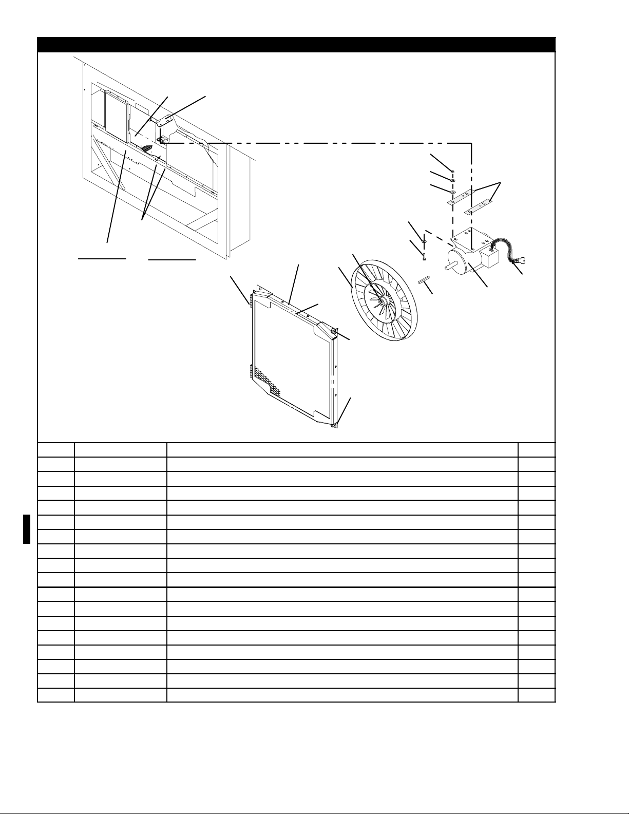
2.19 EVAPORATOR FAN ASSEMBLY AND CONTROLLED A TMOSPHERE -- TRANSFRESH SECTION
14
2
3
13
2
3
4
1
5
6
7
12
11
6
8
9
EFM-1 (Location)
10
EFM-2 (Location)
15
16
Upper back left of unit w/ evap
fan assembly removed
17
18
Partial view of the lower left
corner of the unit.
30T-292PL
Page 40

2.19 EVAPORATOR FAN ASSEMBLY AND CONTROLLED A TMOSPHERE -- TRANSFRESH SECTION
Item Part Number Description Qty
1 69NT43-295 Mounting Bracket, Evaporator Fan Assembly 4
2 69NT35-2692-1 Washer, Fender 8
3 34-00663-11 Washer, Lock, 1/4 -- SST 8
4 34-06165-09 Screw, Hex Head, 1/4-20 x 1-1/4 lg. -- SST 8
5 34-00795-17 Nut, Self Locking, 5/8-18 -- SST 2
6 34-00616-06 Washer, Special, 5/8 -- SST 4
7 38-00577-00 Fan, Evaporator 2
8 48-00262-00 Stator, Evaporator 2
9 58-04066-00 Protector -- Mylar 2
10 54-00585-00 Motor, Evaporator Fan -- Includes: 2
NS 04-50027-00 Bearing, Front (Shaft End) 1
NS 04-50027-01 Bearing, Rear (Opposite Shaft End) 1
NS 22-50088-00 Capacitor (20 mF) High Speed 1
NS 22-01613-34 Pin #16 1
NS 22-01892-00 Plug Assembly, Motor (Located on Wire Harness) -- Includes: 1
NS 22-01614-03 Plug 1
NS 22-01613-15 Contacts A/R
NS 22-01892-01 Receptacle Assembly, Motor -- Includes: 1
NS 22-01614-02 Receptacle 1
NS 22-01614-05 Strain Relief 1
NS 22-01613-14 Contacts A/R
11 66U1-5321-3 Washer, Flat, 1/4 -- SST 8
12 34-06165-09 Screw, Hex Head, 1/4-20 x 1-1/8 lg. -- SST 8
CONTROLLED ATMOSPHERE -- TRANSFRESH
-- 76-00681-01 Kit, Transfresh Field Installation (For units with NO Transfresh Provision) -Includes:
13 34-00655-28 Screw, Hex Head, 1/4-20 x 3-1/2 lg. -- SST 4
14 69NT35-6348 Bracket 2
NS 58-04290-00 Pipe Assembly, PVC 1
*15 69NT35-8734-4 Cable Assembly, Transfresh Communications Connector (TCC) 1
*16 69NT35-8734-16 Panel Assembly, Transfresh 1
*17 69NT35-8734-12 Cable, Power -- A2C (Transfresh) 1
*18 69NT35-8734-5 Hose Assembly, Air (Transfresh) 1
*NS 69NT35-8734-14 Cable Assembly, Rear (Transfresh) 1
*NS 69NT35-8734-6 Fuse Assembly, In-line (Transfresh) 1
NOTE
* Contact - - TransFresh Corp., P.O. Box 1788, Salinas, CA 93902 to order these parts.
--
31 T-292PL
Page 41

3.20 EVAPORATOR COIL SECTION -- REAR PANELS REMOVED
29
30
29
2
32
20
2020
(RTS & RRS)
1
14
6
6
11
12
3
4
7
8
9
10
4
5
T-292PL
19
32
20
16
17
18
28
22
23
13
15
242625
Change 06/10
Page 42

3.20 EVAPORATOR COIL SECTION -- REAR PANELS REMOVED
Item Part Number Description Qty
1 12-00500-01SV Sensor Assembly (RRS & RTS) 1
2 -- Sensor, Thermistor, (Temperature Recorder) -- RefertoSection3.26 --
3 12-00495-20 Sensor, Thermistor, Defrost (DTS) 1
4 34-01178-22 Screw, Hex Head, #8-32 x 1/2 lg. -- SST 3
5 66U1-6912-16 Thermostat, Heat Termination (HTT) 1
6 AU11JR171 Washer, Lock, 1/4 -- SST 10
7 69NT35-6522 Retainer (For Heaters) 3
8 69NT35-6532 Clip (For Heaters) 4
9 69NT35-2692-1 Washer, Flat, 1/4 -- SST 2
10 66U1-5371-13 Screw, Hex Head, #10-24 x 1.25 lg. -- SST 2
11 66U1-5361-25 Capscrew, Hex Head, 1/4-20 x 3/4 lg. -- SST 9
12 66U1-5321-3 Washer, Flat, 1/4 -- SST A/R
13 14-00212-03SV Valve, Quench Expansion 1
14 24-00006-02 Heater, Evaporator Coil 4
15 24-00003-00 Heater, Drain Pan 1
16 44-01050-16 Clamp, Tube -- Nylon 2
17 66U1-5371-6 Screw, Hex Head, #10-24 x .75 lg. -- SST 2
18 66U1-5321-8 Washer, Flat, #10 -- SST 2
19 -- USDA Option -- RefertoSection3.21 --
20 14-00493-11 Sensor, Thermistor, (CPSS) 1
21 58-04026-26 Protector, Mylar 2
22 KA66FA138 Clamp,Tube13/82Holes 1
23 66U1-5371-7 Screw, Machine, Hex Head, #10-24 x .50 lg. -- SST
24 14-00263-05 Valve, Stepper Motor -- Includes: 1
25 14-00263-20 Piston and Motor Assembly -- Includes: 1
26 22-02392-03 Connector (To Expansion Controller Module) 1
NS 22-02393-01 Pin, 18-20 Gauge (Used on 22-02392-03) 4
NS 22-02394-03 Seal (Used on 22-02392-03) 4
OPTION 4 HELICOX HATCHED
81-01574-00 Coil, Evaporator (Does not include thermostats or heaters) -- Used only
27
on PIDS NT0826, NT0862, and NT0865
81-01841-00 Coil, Evaporator (Does not include thermostats or heaters)
28 14-00273-02 Valve, Thermostatic Expansion, Hermetic 1
DEHUMIDIFICATION
-- 76-00675-01 Kit, Humidity Sensor(Field installation, units provisioned for -- See Unit
Matrix, T-300) -- Includes:
29 10-00413-00 Sensor, Humidity (HS) 1
30 66U1-5371-10 Screw, Hex Head, #10-24 x 1.00 lg. -- SST 4
31 66U1-5321-8 Washer, Flat, #10 -- SST 2
32 68-13181-00 Bracket Assembly, Humidity Sensor 1
2
1
--
Change 06/10
33
T-292PL
Page 43

2.21 USDA SECTION
12
10
OPTION -- D
1
2
4
6
3
5
6
OPTION -- V
1
2
4
6
7
8
9
OPTION 1 OR 2
11
34T-292PL
Page 44

2.21 USDA OPTION
Item Part Number Description Qty
OPTION D
1 22-01660-08 Plug, Sealing 4
2 22-01660-00 Receptacle (PR1, PR2, PR3, Cargo Probe 4) (3 Pin) 4
3 22-01660-03 Receptacle, Interrogator (ICR) (5 Pin)1 1
NS 69NT41-992 Plate Assembly, USDA -- Includes: 1
4 69NT43-175 Cap, Dust, with Tether (3 Pin) 4
5 69NT43-176 Cap, Dust, with Chain (5 Pin) 1
6 22-01613-14 Contact, Pin, #16 (Used with 22-01660-00 & 22-01660-03) 13
NS 22-01660-04 Plug, Interrogator Socket (ICR) (5 Pin) 1
OPTION V
1 22-01660-08 Plug, Sealing 4
2 22-01660-00 Receptacle (PR1, PR2, PR3, Cargo Probe 4) (3 Pin) 4
4 69NT43-175 Cap, Dust, with Tether (3 Pin) 4
6 22-01613-14 Contact, Pin, #16 (Used with 22-01660-00 & 22-01660-03) 13
7 22-02412-00 Receptacle, Interrogator (5 Pin) 1
8 22-02413-00 Cap, Dust, with Tether (5 Pin) 1
22-02398-02 Socket, Contact (Silver Plated) A/R
9
22-02398-03 Socket, Contact (Gold Plated) A/R
FIELD INSTALLED KITS (for units with USDA provision , see T-- 300 )
-- 76-00684-00 Kit, USDA (For field installation, units provisioned for rear-mounted
USDA -- See T-300) -- Includes all of OPTION D and the following:
NS 69NT40-507-1 Door Assembly (Included and Used with REAR-mount USDA only) 1
-- 76-00676-00 Kit, USDA (For field installation, units provisioned for side-mounted
USDA -- See T-300) -- Includes all of OPTION D:
USDA PROBE KITS
OPTION 1
10 12-00342-03 Sensor Assembly, 600” lg. (15M) (USDA Probe) -- Includes: A/R
11 22-50127-00 Plug, Socket (PR1, PR2, PR3, Cargo Probe 4) 1
12 22-01613-15 Contact, Socket, #16 (Used with 22-50127-00 & 22-01660-04) A/R
OPTION 2
12-00342-02 Sensor Assembly, 540” lg. (13.5M) (USDA Probe) -- Includes: A/R
10
12-00342-04 Sensor Assembly, 600” lg. (15M) (USDA Probe) -- Includes: A/R
11 22-50127-00 Plug, Socket (PR1, PR2, PR3, Cargo Probe 4) 1
12 22-01613-15 Contact, Socket, #16 (Used with 22-50127-00 & 22-01660-04) A/R
NOTE
Do not mix silver pins with gold pins and sockets.
--
--
35 T-292PL
Page 45

2.22 BACK PANEL ASSEMBLY -- OPTION 1 -- ALUMINUM BOLTED
10
11
3
1
2
3
13
10
11
4
5
3
6
7
9
6
66
12
8
3
6
7
36T-292PL
Page 46

2.22 BACK PANEL ASSEMBLY -- OPTION 1 -- ALUMINUM BOLTED
Item Part Number Description Qty
1 69NT43-464 Grille, Top (Unpainted) 1
2 34-00928-09 Rivet, Blind, 5/32 Diameter, Grip Range -- 1/8-1/4 21
3 66U1-7982-2 Rivet, TIR, 3/16 Diameter, Grip Range -- 5/64-11/64 4
4 69NT41-942-3 Panel Assembly, Upper PID Number 0699 and below -- Includes: 1
NS NSS Drain Pan, Side (Location -- Behind upper panel) 2
NS NSS Drain Pan, Center (Location -- Behind upper panel -- Top) 1
5 42-00334-00 Gasket (Location -- Behind upper panel) 1
4 76--00746--00 Panel Assembly, Upper PID Number 0700 and above -- Includes: 1
NS NSS Drain Pan (Location -- Behind upper panel) 2
5 42-00334-00 Gasket (Location -- Behind upper panel) 1
NS 66U1-8075 Gasket (25 ft., Cut to length) A/R
6 34-00928-02 Rivet, Blind, 1/8 Diameter, Grip Range -- 1/8-3/16 46
7 34-00928-03 Rivet, Blind, 1/8 Diameter, Grip Range -- 3/16-1/4 3
8 68-13475-00 Panel, Bottom, (Painted) 1
8 68-13475-08 Panel, Bottom, (Unpainted) 1
9 68-13475-01 Panel, Bottom (Provision for heat exchanger location), (Painted) 1
9 68-13475-09 Panel, Bottom (Provision for heat exchanger location), (Unpainted) 1
10 66U1-2403 Screw, Machine, Truss Head, #10-24 x 1/2 lg. -- SST 20
11 69NT35-2692 Washer, Fender, #10 x 1.00 OD -- SST 20
12 69NT35-2257 Duct, Air 1
13 62-02822-01 Label, Carrier Transicold 1
37 T-292PL
Page 47

2.23 BACK PANEL ASSEMBLY -- OPTION 2 -- ALUMINUM BOLTED WITH USDA DOOR
10
11
3
1
2
3
18
10
11
3
6
12
13
14
15
16
17
7
4
3
6
7
9
6
66
8
38T-292PL
Page 48

2.23 BACK PANEL ASSEMBLY -- OPTION 2 -- ALUMINUM BOLTED WITH USDA DOOR
Item Part Number Description Qty
1 69NT43-464 Grille, Top 1
2 34-00928-09 Rivet, Blind, 5/32 Diameter, Grip Range -- 1/8-1/4 17
3 66U1-7982-2 Rivet, TIR, 3/16 Diameter, Grip Range -- 5/64-11/64 4
4 69NT41-942-3 Panel Assembly, Upper PID Numbers 0699 and below-- Includes: 1
NS NSS Drain Pan, Side (Location -- Behind upper panel) 2
NS NSS Drain Pan, Center (Location -- Behind upper panel) 1
5 42-00334-00 Gasket (Location -- Behind upper panel) 1
4 76--00746--00 Panel Assembly, Upper PID Numbers 0700 and and above -- Includes: 1
NS NSS Drain Pan (Location -- Behind upper panel) 2
5 42-00334-00 Gasket (Location -- Behind upper panel) 1
6 34-00928-02 Rivet, Blind, 1/8 Diameter, Grip Range -- 1/8-3/16 41
7 34-00928-03 Rivet, Blind, 1/8 Diameter, Grip Range -- 3/16-1/4 6
8 68-12881-00 Panel, Bottom 1
9 68-12881-01 Panel, Bottom (Provision for heat exchanger location) 1
10 66U1-2403 Screw, Machine, Truss Head, #10-24 x 1/2 lg. -- SST 18
11 69NT35-2692 Washer, Fender, #10 x 1.00 OD -- SST 18
NS 66U1-8075 Gasket (25 ft., Cut to length) A/R
12 69NT40-567-2 Door Assembly, Access-- Includes: 1
13 44-00376--00 Hinge 1
14 69NT35-7662-2 Spacer, Hinge 1
15 34-01150-30 Washer, Retaining 2
16 34-01150-04 Stud, 1/4 Turn, 0.97 lg. 2
17 34-00928-02 Rivet, Blind, 1/8 Diameter, Grip Range -- 1/4-5/16 6
18 62-02822-01 Label, Carrier Transicold 1
39 T-292PL
Page 49

2.24 BACK PANEL ASSEMBLY -- OPTION 4 -- ALUMINUM HINGED
10
11
13
10
12
13
9
2
1
2
3
4
5
6
8
5
5
7
5
6
40T-292PL
Page 50

2.24 BACK PANEL ASSEMBLY -- OPTION 4 -- ALUMINUM HINGED
Item Part Number Description Qty
1 69NT43-464 Grille, Top 1
2 34-00928-09 Rivet, Blind, 5/32 Diameter, Grip Range -- 1/8-1/4 37
3 69NT41-942-4 Panel Assembly, Upper PID Number 0699 and Below -- Includes: 1
NS NSS Drain Pan, Side 2
NS NSS Drain Pan, Center 1
4 42-00334-00 Gasket (Location -- Behind upper panel) 1
3 76--00746--01 Panel Assembly, Upper PID Number 0700 and Above -- Includes: 1
NS NSS Drain Pan 1
4 42-00334-00 Gasket (Location -- Behind upper panel) 1
5 34-00928-02 Rivet, Blind, 1/8 Diameter, Grip Range -- 1/8-3/16 46
6 34-00928-03 Rivet, Blind, 1/8 Diameter, Grip Range -- 3/16-1/9 3
68-13475-00 Panel, Bottom, (Painted) 1
7
68-13475-08 Panel, Bottom, (Unpainted) 1
68-13475-01 Panel, Bottom (Provision for USDA location), (Painted) 1
8
68-13475-09 Panel, Bottom (Provision for USDA location), (Unpainted) 1
NS 66U1-8075 Gasket (25 ft., Cut to length) A/R
9 69NT35-3282 Hinge 4
10 34-01150-30 Washer, Retaining 14
11 34-01150-06 Stud, 1/4 Turn, 1.03 lg. 6
12 34-01150-03 Stud, 1/4 Turn, 0.94 lg. 8
13 34-01150-31 Receptacle, Retaining 14
41 T-292PL
Page 51

2.25 BACK PANEL ASSEMBLY -- OPTION 5 -- STAINLESS STEEL HINGED
10
11
13
10
12
13
9
2
1
2
3
4
5
6
8
55
7
5
6
42T-292PL
Page 52

2.25 BACK PANEL ASSEMBLY -- OPTION 5 -- STAINLESS STEEL HINGED
Item Part Number Description Qty
1 69NT43-464 Grille, Top 1
2 34-00928-09 Rivet, Blind, 5/32 Diameter, Grip Range -- 1/8-1/4 37
3 69NT41-942-5 Panel Assembly, Upper PID Number 0699 and Below -- Includes: 1
NS NSS Drain Pan, Side 2
NS NSS Drain Pan, Center 1
4 42-00334-00 Gasket (Location -- Behind upper panel) 1
3 76--00746--02 Panel Assembly, Upper PID Number 0700 and Above-- Includes: 1
NS NSS Drain Pan, 2
4 42-00334-00 Gasket (Location -- Behind upper panel) 1
5 34-00928-02 Rivet, Blind, 1/8 Diameter, Grip Range -- 1/8-3/16 46
6 34-00928-03 Rivet, Blind, 1/8 Diameter, Grip Range -- 3/16-1/9 3
7 69NT35-6598 Panel, Bottom. SST 1
8 69NT35-6598-1 Panel, Bottom (Provision for USDA location), SST 1
NS 66U1-8075 Gasket (25 ft., Cut to length) A/R
9 69NT35-3282 Hinge 4
10 34-01150-30 Washer, Retaining 14
11 34-01150-06 Stud, 1/4 Turn, 1.03 lg. 6
12 34-01150-03 Stud, 1/4 Turn, 0.94 lg. 8
13 34-01150-31 Receptacle, Retaining 14
43 T-292PL
Page 53

2.26 PARTLOW TEMPERATURE RECORDER
31
33
12
13
16
17
30
31
32
15
9
8
5
11
10
4
27
18
19
2
3
26
28
29
14
6
1
Item Part Number Description Qty
OPTION 1, OPTION 2, OPTION 3 AND OPTION 4
-- 76-00701-04
OPTION 1
1 12-00421-02 Temperature Recorder without Simpson Probe--Includes: 1
-- 76-00701-00
OPTION 2
1 12-00421-00 Temperature Recorder with Simpson Probe--Includes: 1
-- 76-00701-01
OPTION 3
1 12-00421-01 Temperature Recorder, Battery Operated w/o Simpson Probe
-- 76-00701-12
OPTION 4
1 12-00421-03 Temperature Recorder, Battery Operated w/ Simpson Probe --Includes: 1
Recorder Kit--Partlow without Simpson Probe -- Includes: Recorder, Box
and Door Assy’s
Recorder Kit--Partlow with Simpson Probe -- Includes: Recorder, Box and
Door Assy’s
Recorder Kit--Partlow, Battery Operated without Simpson Probe -- Includes:
Recorder, Box and Door Assy’s (For field installation, units provisioned
for -- Refer to Unit Matrix T--300 )
--Includes:
Recorder Kit--Partlow, Battery Operated without Simpson Probe -- Includes:
Recorder, Box and Door Assy’s(For field installation, units provisioned
for -- Refer to Unit Matrix T--300 )
7
22
21
20
23
24
25
1
1
1
1
1
44T-292PL
Page 54

OPTION 1 - PARTLOW WITHOUT PROBE & OPTION 2 - PARTLOW WITH PROBE (Continued)
Item Part Number Description Qty
2 09-00104-05 Kit, Stylus -- Includes: 1
3 NSS Screw , Round Head, #2-56 x 3/16 lg. 2
4 09-00296-00 Mechanism and Platen Assembly 1
5 09-00345-00 Main Lever and Push Rod Assembly (Includes Setscrews) 1
6 09-00344-00 Rod, Push 1
7 09-00114-00 Key, Clock Winding 1
8 09-00119-00 Nut and Chain, Chart (Sonceboz Clock) 1
8 09-00180-00 Nut and Chain, Chart (Gluck Clock) 1
9 PL Screw, Round Head #6-32 x 5/16 7
10 09-00118-00 Flange, Chart Drive (Sonceboz) 1
10 09-00180-01 Flange, Chart Drive (Gluck) 1
11 09-00123-00 Clock, 31 Day, CCW (Counterclockwise) 1
11 09-00302-00 Clock, 31 Day, CCW (Counterclockwise) Battery Operated
Used with P/N 12-00421-01 & 03
12 09-00137-00 O-Ring, Element Flange 4
13 09-00209-00 Element, 9 ft. lg. -- Includes: 1
NS 09-00222-00 Sensor, Thermistor (Accessory 344 and Jack) -- 15 ft. lg. 1
13 09-00236-00 Element, 10 ft. lg. Used with P/N 12-00421-01 & -02 1
14 09-00136-00 Screw, Flange 2
15 76-00701-06SV Box Assembly -- Includes: 1
16 34-01142-01 Receptacle -- #12 2
17 34-00928-01 Rivet, Blind, .125 Diameter, Grip Range .063 - .125 -- SST 4
NS 09-00303-00 Battery Cover (Includes Hardware) 1
NS 22-02243-00 Pin (Use with Partlow Thermistor Assembly) 3
NS 09-00128-00 Charts _F -- 31 Day (Box of 50) (--20_Fto+80_F) A/R
NS 09-00128-01 Charts _C -- 31 Day (Box of 50) (--25_Cto+25_C) A/R
18 76-00701-05 Door Assembly -- Includes: 1
19 42-01098-01 Gasket, Door 1
20 66U1-6811-8 Screw, Retaining -- SST 2
21 34-06053-00 Washer, 1/4 I.D. x 1 O.D. -- Mylar 2
22 34-06169-00 Washer, Retaining -- SST 2
23 69NT35-5022-5 Window 1
24 69NT35-5352-1 Gasket 1
25 34-00795-09 Nut, Selflock, 1/4-20 -- SST 4
26 44-00374-00 Hinge -- SST 2
27 58-04101-07 Protector, .010 Thick x .75 x 2.63 -- Mylar 4
28 34-06179-00 Screw, Hex Head, Slotted, #10-24 x 7/16 lg. -- SST 8
29 34-06179-04 Screw, Hex Head, Slotted, #10-24 x 5/16 lg. -- SST 4
30 66U1-5321-7 Washer, Flat, 1/4 -- SST 2
31 66U1-5361-25 Screw, Cap, Hex Head, 1/4-20 x .75 lg. -- SST 4
32 34-06053-13 Washer, Retaining, .19 I.D. x .80 O.D. -- Mylar 2
33 69NT35-2692-1 Washer, Fender, 1/4 I.D. x .993-1.015 O.D. 2
NS PL Battery -- 1.5 volt (D cell size) Alkaline 1
1
45 T-292PL
Page 55

2.27 SAGINOMIYA TEMPERATURE RECORDER
31
32
17
12
13
4
10
9
1
14
20
19
21
22
23
11
15
16
8
24
7
5
6
134
2
32 27
33
26
27
28
29
25
26
30
46T-292PL
Page 56

2.27 SAGINOMIYA TEMPERATURE RECORDER
Item Part Number Description Qty
OPTION 5 -- SAGINOMIYA WITHOUT PROBE AND & OPTION 6 -- SAGINOMIYA WITH PROBE
-- 76-00701-03
OPTION 5
1 12-01094-00 Recording Thermometer w/Return Sensor -- Includes: 1
-- 76-00701-02
OPTION 6
1 12-01094-01 Recording Thermometer w/Return and Supply Sensor -- Includes: 1
2 09-00365-00 Stylus,LiftArm(See NOTE) 1
3 09-00364-00 Element Assembly 1
4 09-00367-00 Element Assembly (Used on P/N 12-01094-01) 1
5 09-00362-00 Indicator, Voltage 1
6 09-00363-00 Plate, Recorder 1
7 PL Battery (Mallory R14P/S 1.5 vdc) 1
8 09-00326-00 Shaft, Chart 1
9 09-00329-00 Block, Terminal 1
10 09-00322-00 Timer (31 Day) 1
11 09-00325-00 Nut, Chart (Male) 1
12 69NT40-402-1 Sensor Assembly, Return Temperature (Used on 76-00701-02) --
NS 12-01095-00 Sensor, Thermistor 1
13 22-02370-00 Jack, Phono (Used on 76-00701-02) 2
14 76-00701-06SV Box Assembly, Recorder -- Includes: 1
15 34-01142-01 Receptacle, Retaining 2
16 34-00928-01 Rivet, Blind, .125 Diameter, Grip Range .063--.125 -- SST 4
17 34-06053-13 Washer, .195 I.D. x .80 O.D. -- Mylar 2
18 34-01142-01 Receptacle, Retaining 2
19 76-00701-05 Door Assembly, Recorder Box -- Includes: 1
20 42-01098-01 Gasket, Door 1
21 66U1-6811-8 Screw, Retaining -- SST 2
22 34-06169-00 Washer, Retaining -- SST 2
23 34-06053-00 Washer, 1/4 I.D. x 1.00 O.D. -- Mylar 4
24 69NT35-5022-5 Window, Lexan 1
25 69NT35-5352-1 Gasket, Window 1
26 44-00374-00 Hinge Assembly -- SST 2
27 58-04101-07 Protector, Mylar (For Hinge) 4
28 34-06179-00 Screw, Hex Head, #10-24 x 7/16 lg. -- SST 4
29 34-06179-04 Screw, Hex Head, #10-24 x 5/16 lg. -- SST 4
30 34-00795-09 Nut, Selflock, #10-32 -- SST 4
31 66U1-5321-7 Washer, Flat, 1/4 -- SST 2
32 66U1-5361-25 Screw, Cap Hex Head, 1/4-20 x .75 lg. -- SST 4
33 69NT35-2692-1 Washer, Fender, 1/4 I.D. x .993-1.015 O.D. 2
NS 09-00128-00 Charts _F -- 31 Day (Box of 50) (--20_Fto+80_F) A/R
NS 09-00128-01 Charts _C -- 31 Day (Box of 50) (--25_Cto+25_C) A/R
NOTE: The quantity is two for these charts when using P/N 12-01094-01.
Recording Thermometer Assembly w/Return Sensor -- Includes: Recorder,
Box and Door Assy’s
Recording Thermometer Assembly w/Return & Supply Sensor -- Includes:
Recorder, Box and Door Assy’s
Includes:
1
1
1
47 T-292PL
Page 57

2.28 OPTION 7 AND OPTION 8 -- ELECTRONIC PARTLOW TEMPERATURE RECORDER
OPTION -- 7 and 8
5
4
7
8
9
14
17
1
2
3
12
11
18
19
6
24
10
13
2.29 OPTION 9 -- NO TEMPERATURE RECORDER
OPTION 9
25
27
28
30
23
21
16
15
18
20
22
26
27
29
48T-292PL
Page 58

2.28 OPTION 7 AND OPTION 8 -- ELECTRONIC PARTLOW TEMPERATURE RECORDER
Item Part Number Description Qty
-- 76-00701-11
OPTION 7
1 12-00464-06 Electronic Temperature Recorder 1
-- 76-00701-10
OPTION 8
1 12-00464-05 Electronic Temperature Recorder 1
2 76-00701-05 Door Assembly -- Includes: 1
3 42-01098-01 Seal, Door -- Rubber 1
4 66U1-6811-8 Screw, Retaining -- .300 -- .625 Panel Thickness -- SST 2
5 34-06053-00 Washer, .25 I.D. x 1.00 O.D. -- Mylar 4
6 34-06169-00 Washer, Retaining -- SST 2
7 69NT35-5022-5 Window 1
8 69NT35-5352-1 Gasket 1
9 34-00795-09 Nut, Selflock, 1/4-20 4
10 44-00374-00 Hinge 2
11 58-04101-07 Protector -- Mylar 4
12 34-06179-04 Screw, Hex Head, SEMS, #10-24 x 5/16 lg. 4
13 34-06179-00 Screw, Hex Head, #10-24 x 7/16 lg. -- SST 4
14 76-00701-06SV Box Assembly -- Includes: 1
15 58-00065-67 Grommet, 3/8 ID x 1.25 OD 1
16 58-00065-70 Plug, Hole, .50 DIA 2
17 66U1-5321-7 Washer, Flat, 1/4 -- SST 2
18 66U1-5361-25 Screw, Cap, Hex Head, 1/4-20 x .75 lg. -- SST 4
19 34-06053-13 Washer, Retaining, .19 I.D. x .80 O.D. -- Mylar 2
20 69NT35-2692-1 Washer, Fender, 1/4 I.D. x .993-1.015 O.D. 2
21 34-06053-05 Washer, 1/4 I.D. x 1 O.D. -- Mylar 4
22 34-06053-03 Washer, .25 I.D. x .19 O.D. -- Mylar 2
23 34-06179-00 Screw, Hex Head, SEMS, #10-24 x 7/16 lg. 4
24 09--00371--00 Stylus, Elecronic Partlow Kit, Includes:
NS -- Chart -- Owner Supplied A/R
NS 09-00128-00 Charts _F -- 31 Day (Box of 50) (--20_Fto+80_F) A/R
NS 09-00128-01 Charts _C -- 31 Day (Box of 50) (--25_Cto+25_C) A/R
Partlow Recorder Kit, Standard -- Includes: Recorder, Box & Door Assy’s
(For field installation, units provisioned for -- Refer to Manual T-300 )
Partlow Recorder Kit, Special -- Includes: Recorder, Box & Door Assy’s
(For field installation, units provisioned for -- Refer to Manual T-300 )
1
1
2.29 OPTION 9 -- NO TEMPERATURE RECORDER
Item Part Number Description Qty
25 68-12658-01 Panel 1
26 66U1-5321-7 Washer, Flat, 1/4 -- SST 2
27 66U1-5361-25 Screw, Cap Hex Head, 1/4-20 x .75 lg. -- SST 4
28 69NT35-2692-1 Washer, Fender, 1/4 I.D. x .993-1.015 O.D. 2
29 34-06053-13 Washer, Retaining, .195 I.D. x .80 O.D. -- Mylar 2
30 34-06053-03 Washer, .25 I.D. x 1.00 O.D. -- Mylar 2
49 T-292PL
Page 59

2.30 COMPRESSOR MOUNTING COMPONENTS AND GUARD
12
13
15 16
8
17
14
16
18 19 20
21 22
45
23
9
24 25
16
18
11
10
11
16
18
19
29
6
8
7
32
33
34
35
36
1
2
26
3
16
18
27
28
30
50T-292PL
Page 60

2.30 COMPRESSOR MOUNTING COMPONENTS AND GUARD
Item Part Number Description Qty
1 18-00095-20SV Compressor,Scroll -- Includes: (See Section 4) --
2 42-00384-01 Seal, Rotolock, 1-14 1
NS 42-00384-02 Seal, Rotolock, 1-1/4--12 2
NS 07--00427--00 Compressor Oil 2
3 18-00077-41 O-Ring 1
4 58-04461-00 Shockmount, Bushing 1
5 58-04461-01 Shockmount, Ring 1
6 58-04451-00 Mount, Resilient, 80A 4
7 34-06053-20 Washer, Mylar -- 1.50 X .65 4
8 34-06236-00 Washer, .687 X 1.50 X .078 -- SST 8
9 58--04026--62 Protector, Mylar 1
10 48-00350-01SV Base, Compressor (Painted) -- Includes: 1
11 58-04435-00 Protector, Mylar 2
12 34-06174-03 Bolt, Shoulder, 1/2-13 UNC -- SST 4
13 86-04406-00 Bracket Assembly 1
14 86-04405-00 Bracket Assembly 1
15 66U1-5361-47 Bolt, Machine Hex Head, 1/4-20 X 1.25 lg. -- SST 1
16 66U1-5321-7 Washer, Plain 1/4 -- SST 15
17 58-04463-00 Protector, Mylar 1
18 34-06053-00 Washer, Mylar .250 ID X .800 OD 14
19 34-00667-11 Nut, Self Lock 1/4-20 -- SST 5
20 34-00667-13 Nut, Self Lock 3/8-16 -- SST 1
21 66U1-5321-5 Washer, Plain 3/8 N Type A -- SST 1
22 34-06053-02 Washer, Mylar .375 ID X 1.00 OD 1
23 34-06060-03 Washer, Snubbing .537 ID X 2.00 OD 1
24 34-06174-04 Bolt, Shoulder, 3/8-16 UNC -- SST 1
25 34-00655-04 Screw, Cap Hex Head 1/4-20 x .50 -- SST 4
26 22-01914-02 Cable, Power 1
27 66U1-5361-25 Screw, Hex Head, 1/4-20 x 3/4 lg. -- SST 1
28 68-12993-00 Panel, Guard 1
29 66U1-5361-11 Capscrew, Hex Head, 1/4-20 x 1-1/2 lg. -- SST 4
30 68-12758--00 Guard (Blue), Compressor 1
31 68-12758--20 Guard (White), Compressor 1
32 66U1-5321-8 Washer, Flat, #10 -- SST 7
33 34-06053-05 Washer, Mylar, 0.205 ID x 0.600 OD 7
34 66U1-5371-7 Screw, Slotted Head, #10-24 x .50 lg. -- SST 5
35 68-14777-00 Partition 1
36 68--14778--00 Bracket 1
51 T-292PL
Page 61

2.31 TRANSDUCERS
37
38
39
41
40
41
Option T -- Transducer Locations
52T-292PL
Page 62

2.31 TRANSDUCERS
Item Part Number Description Qty
OPTION T -- PRESSURE TRANSDUCERS
37 12-00309-05 Switch, Pressure 1
-- 12-00352-07SV Transducer Kit -- Includes: 1
38 12-00352-07 Transducer , Suction NSS 1
39 22-01713-12 Cable, SPT Patch 1
40 12-00352-00 Transducer, Discharge 1
41 EC39DM070 Core, Check Valve (Used with 40-00604-00 Tee) 3
53 T-292PL
Page 63

2.32 CABLE RESTRAINT COMPONENTS
1
OPTION 1 -- CABLE DOOR
OPTION 3 -- J-HOOK
2
3
4
5
6
25
26
27
28
2
3
4
8
9
10
19
13
14
15
16
17
18
20
21
22
23
24
7
8
9
10
11
12
29
30
31
32
OPTION 5 and 6 -- LEFT SIDE EXTENDED GUARD
34
35
33
OPTION 2, 4, 5 and 6 -- LEFT SIDE
BUNGY CORD
OPTION R -- DUMMY RECEPTICAL
54T-292PL
Page 64

2.32 CABLE RESTRAINT COMPONENTS
Item Part Number Description Qty
OPTION 1 -- CABLE DOOR
1 69NT41-724-4 Cover Assembly w/Latch, Cable Storage -- Includes: 1
2 34-06126-08 Screw, Hex Head, #4-40 x 1/2 lg. -- SST 2
3 34-00662-05 Washer, Flat, #4 --SST 4
4 34-00667-05 Locknut, Hex Head, #4-40 2
5 34-06053-08 Washer, Mylar, 1/8 ID x 3/8 OD 2
6 44-00340-03 Latch 1
7 69NT35-8032 Hinge 2
8 66U1-2403 Screw, Truss Head, #10-24 x 1/2 lg. -- SST 4
9 66U1-5321-8 Washer, Flat, #10 4
10 34-00667-09 Locknut, Hex Head, #10-24 -- SST 4
11 34-06053-05 Washer , Mylar, 3/16 ID x 5/8 OD 4
12 58-04001-02 Protector, Mylar 2
13 58-04001-01 Protector, Mylar 1
14 34-06053-05 Washer, Mylar, 3/16 ID x 5/8 OD 2
15 34-01167-01 Retainer, Nut 1
16 66U1-2403 Screw, Truss Head, #10-24 x 1/2 lg. -- SST 2
17 66U1-5321-8 Washer, Flat, #10 -- SST 2
18 66U1-5331-3 Washer, Lock, #10 -- SST 4
19 44-00340-05 Latch, Catch 1
OPTION 2 -- LEFT BUNGY CORD ONLY
20 69NT35-5992 Cable Restraint 1
21 66U1-5321-7 Washer, Flat, 1/4 -- SST 2
22 66U1-5361-25 Screw, Cap, Hex, Head, 1/4-20 x .75 lg -- SST 2
23 34-06053-03 Washer, Mylar, .25 I.D. X 1.00 O.D. 2
24 66U1-2603 Strap, Tie Down 1
OPTION 3 -- J--HOOK
25 69NT35-8382 Cable Restraint, J-Hook 1
26 58-04026-22 Protector, Mylar 1
27 66U1-5321-7 Washer, Flat, 1/4 -- SST 2
28 66U1-5361-25 Screw, Cap, Hex, Head, 1/4-20 x .75 lg -- SST 2
OPTION 5 -- LEFT BUNGY CORD WITH LEFT EXTENDED GUARD (UseOption2PlustheItemsBelow)
29 68-13310-00 Bracket, Left 1
30 66U1-2403 Screw, Truss Head, #10-24 x 1/2 lg. -- SST A/R
31 66U1-5321-8 Washer, Flat, #10 -- SST A/R
32 34-06053-05 Washer, Mylar, 3/16 ID x 5/8 OD A/R
OPTION R -- DUMMY RECEPTICAL (for use in additon to Options 1--5)
33 22--01679--03 Receptical 1
34 66U1-5321-8 Washer, Flat, #10 SST 4
35 66U1--5371--6 Screw, Cap, Hex, Head, 10--24 x .75 lg -- SST 4
55 T-292PL
Page 65

2.33 VOLTAGE CABLES
13
Item Part Number Description Qty
CLAMPS ON BACK WALL AND CABLE CUTTERS
34-00373-56 Clamp, Tube, Cushioned, 9/16 Diameter (Used with Transicord) A/R
1
34-00373-59 Clamp, Tube, Cushioned, 3/4 Diameter A/R
2 66U1-5381-1 Screw, Hex Head, #10-24 x 3/4 lg. -- SST A/R
3 34-06053-03 Washer, Mylar, 1/4 ID x 1.00 OD A/R
69NT35-6412-2 Clamp, Cable Cutter, 8 AWG cable 1
69NT35-6412 Clamp, Cable Cutter, 10 AWG cable 1
4
69NT35-6412-1 Clamp, Cable Cutter, 11 AWG cable 1
5 58-04026-07 Protector, Mylar A/R
6 66U1-5361-11 Screw, Machined Hex Head, 1/4-20 x 1-1/2 lg. -- SST A/R
7 34-00667-11 Locknut, Hex Head, 1/4-20 -- SST A/R
8 66U1-5321-7 W asher, Flat, 1/4 -- SST A/R
9 34-06053-03 Washer, Mylar, 0.25 I.D. x 1.00 O. D. A/R
STANDARD PARTS FOR ALL 460V CABLES
10 66U1-2583 Heat Shrink Tube (Coil Label) -- “460V” 1
22-02324-01 Bushing (Used with Standard Cable) 4
11
22-02324-05 Bushing (Used with Transicord) 4
OPTION 1 460V CABLES
12 66U1-9782 Cable, Power -- Yellow, 10/4 A/R
13 22-02378-00 Plug, Power 1
OPTION 2 460V CABLES
12 22-01551-00 Cable, Power -- Yellow, 33 amp, 1 1 AWG A/R
13 22-02378-00 Plug, Power 1
OPTION 3 460V CABLES
12 66U1-9782 Cable, Power -- Yellow, 10/4 A/R
13 22-01891--00 Plug, Power 1
OPTION 4 460V CABLES
12 22-01551-00 Cable, Power -- Yellow, 33 amp, 1 1 AWG A/R
13 22-01891--00 Plug, Power 1
1011
12
4
5
6
7
8
9
1
2
3
56T-292PL
Page 66

2.33 VOLTAGE CABLES (Continued)
Item Part Number Description Qty
OPTION 5 460V CABLES
12 22-01551-00 Cable, Power -- Yellow, 33 amp, 1 1 AWG A/R
13 22-01883-00 Plug, Power 1
OPTION 6 460V CABLES
12 22-01551-00 Cable, Power -- Yellow, 33 amp, 1 1 AWG A/R
13 22-01891-00 Plug, Power 1
OPTION 7 460V CABLES
12 66U1-9782 Cable, Power -- Yellow, 10/4 A/R
13 22-01891-01 Plug, Power 1
OPTION 8 460V CABLES
12 66U1-9782 Cable, Power -- Yellow, 10/4 A/R
13 22-01932-00 Plug, Power 1
OPTION 9 460V CABLES
12 66U1-9782 Cable, Power -- Yellow, 10/4 A/R
13 22-02232-00 Plug, Power 1
STANDARD PARTS FOR ALL 230V CABLES
10 66U1-2583-1 Heat Shrink Tube (Coil Label) -- “230V” 1
11 22-02324-02 Bushing (Used with 8 AWG) 4
12 66U1-9782-1 Cable, Power -- Black, 35 amps, 8 AWG A/R
OPTION 1 230V CABLES
13 22-02188-00 Plug, Power 1
OPTION 2 230V CABLES
13 22-02375-00 Plug, Power 1
OPTION 3 230V CABLES
13 66U1-6782-3 Plug, Power 1
OPTION 4 230V CABLES
13 22-01744-00 Plug, Power (PL) 1
OPTION 5 230V CABLES
13 22-02322-00 Plug, Power 1
OPTION 6 230V CABLES
13 22-01884-00 Plug, Power 1
OPTION 7 230V CABLES
13 66U1-6782 Plug, Power 1
OPTION 8 230V CABLES
13 22-01931-00 Plug, Power 1
OPTION 9 230V CABLES
13 22-01906-00 Plug, Power 1
57 T-292PL
Page 67

2.34 AUTOTRANSFORMER KIT
25
26
27
28
11
14
20
21
Item Part Number Description Qty
STANDARD PARTS INCLUDED IN EVERY 76-00670 SERVICE KIT
-- 76--00670--xx Standard Parts Included in the Service Kits Include: 1
1 66U1-5371-7 Screw , Hex Head, #10-24 x 1/2 lg. -- SST 4
2 66U1-5321-8 Washer, Flat, #10 -- SST 4
3 34-06053-05 Washer, Mylar, 0.205 ID x 0.600 OD 4
4 34-06053-00 Washer, Mylar, 0.250 ID x 0.800 OD 5
5 AU11JR171 Washer, Lock, 1/4 -- SST 5
6 AA06JA170 Screw, Hex Head, 1/4-20 x 1.00 lg. 5
7 66U1-2603 Strap, Tie Down 1
69NT35-6412-2 Clamp, Cable Cutter, 8 AWG cable 1
69NT35-6412 Clamp, Cable Cutter, 10 AWG cable 1
8
69NT35-6412-1 Clamp, Cable Cutter, 11 AWG cable 1
9 58-04026-07 Protector, Mylar 1
10 66U1-5361-11 Screw, Machined Hex Head, 1/4-20 x 1-1/2 lg. -- SST 2
11 66U1-5321-7 Washer, Flat, 1/4 -- SST A/R
12 34-00667-11 Locknut, Hex Head, 1/4-20 -- SST 2
13 69NT35-5992 Clamp, Tie Down Strap 1
14 66U1-5361-25 Bolt, Hex Head, 1/4-20 x 3/4 lg. -- SST A/R
15 34-06053-03 Washer, Mylar, 0.25 ID x 1.00 O.D. 2
16 69NT43-374 Bracket Assembly 1
17 58-04026-17 Protector, Mylar 1
11
13
14
15
29
30
31
7
4
8
9
10
11
12
19
23
24
18
1
2
3
11
22
16
17
4
11
5
6
58T-292PL
Page 68

2.34 AUTOTRANSFORMER KIT (Continued)
2
2
Item Part Number Description Qty
OPTION 1 -- AUTOTRANSFORMER
See Previous Page for Standard Parts Included in the Kit and use with Items Below
-- 76-00670-02 T ransformer Kit, Field Installation, without CB2 -- Includes: 1
18 10-01139-04 Transformer, Dual Voltage Modular 1
NS 22-01778-00 Terminal Block -- Used only without CB2 1
19 69NT43-470-1 Box Assembly 1
20 69NT35-8382 Clamp, Tie Down Strap 1
21 58-04026-22 Protector, Mylar 1
OPTION 2 -- AUTOTRANSFORMER WITH CB2 AND RECEPTACLE
See Previous Page for Standard Parts Included in the Kit and use with Items Below
-- 76-00670-01 T ransformer Kit, Field Installation, with CB2 -- Includes: 1
18 10-01139-04 Transformer, Dual Voltage Modular 1
19 69NT43-470 Box Assembly -- Used only with CB2 1
22-01679-00 Receptacle -- 32 Amp 1
22-01679-01 Receptacle w/ Screw Cap -- 32 Amp, Alternate, SOLD SEPARATELY 1
20 69NT35-8382 Clamp, Tie Down Strap 1
21 58-04026-22 Protector, Mylar 1
-- 76-00667-05 Circuit Breaker Kit, Field Installation -- Includes: 1
23 10-00083-05 Circuit Breaker, 70 amp -- 250 vac, 50/60 hz 1
24 66U2-1531 Boot -- Includes: 1
NS NSS Frame 1
NS NSS Screw, Self Sealing, #6-32 x 3/8 lg. -- SST 6
OPTION 3 -- AUTOTRANSFORMER WITH CB2 AND BRIDGING UNIT
See Previous Page for Standard Parts Included in the Kit and use with Items Below
-- 76-00670-03 T ransformer Kit, Field Installation, with CB2 and TBU -- Includes: 1
18 10-01139-04 Transformer, Dual Voltage Modular 1
19 69NT43-470-2 Box Assembly 1
20 69NT35-8382 Clamp, Tie Down Strap 1
21 58-04026-22 Protector, Mylar 1
-- 76-00667-05 Circuit Breaker Kit, Field Installation -- Includes: 1
23 10-00083-05 Circuit Breaker, 70 amp -- 250 vac, 50/60 hz 1
24 66U2-1531 Boot -- Includes: 1
NS NSS Frame 1
NS NSS Screw, Self Sealing, #6-32 x 3/8 lg. -- SST 6
25 12-00474-00 Bridge Unit, Transformer 1
26 42-00470-00 Gasket, Transformer Bridge Unit 1
27 34-06221-00 Screw, Hex Head, #10-24 x 2.50 lg. -- SST 2
28 34-00667-09 Locknut, Hex Head, #10-24 -- SST 2
29 66U1-5321-8 Washer, Flat #10 -- SST 2
30 34-06053-05 Washer, Mylar 0.205 I.D. x 0.600 O.D. 2
31 22-02324-01 Bushing, 0.142 I.D. x 0.472 O.D. 3
OPTION 4 -- AUTOTRANSFORMER WITH CB2 AND RECEPTACLE
See Previous Page for Standard Parts Included in the Kit and use with Items Below
-- 76-00670-04 T ransformer Kit, Field Installation, with CB2 -- Includes:
Everything in kit 76-00670-01 except replace Item #22 with below
22 22-01734-01 Receptacle -- 32 Amp 1
1
59 T-292PL
Page 69

2.35 LABELS AND DECALS (Not Applicable to All Units)
11
7
1
12
VIEW -- INSIDE CONTROL BOX
2
3
4
10
9
8
Item Part Number Description Qty
STANDARD LABELS
1 62-02531-00 Decal, Carrier Thinline 1
2 69NT35-3867 Label, Economy Mode 1
3 69NT35-3907 Label, Humidity Control Sensor 1
4 62-02721-07 Label, Function Code -- English 1
62-02562-00 Label, Micro-Link 2i with USDA 1
5
62-02562-01 Label, Micro-Link 2i 1
6 62-02444-01 Label, Charge with R-134a 1
62-10259-00 Label, R-134a -- Ozone Protection -- English 1
7
62-02530-01 Label, R-134a -- Ozone Protection, Umbrella Only -- English 1
8 62-02458-01 Label, POE Compressor Oil 1
9 62-02785-00 Label, CE 1
NS 69NT35-6118 Label, USDA (Location -- Back of Unit, top left side) 1
5
13
6
14
60T-292PL
Page 70

2.35 LABELS AND DECALS (Continued)
Item Part Number Description Qty
OPTION 1 -- ENGLISH
10 62-02720-00 Label, Operating Instructions (Partlow w/ Return Air) 1
10 62-02743-14 Label, Operating Instructions (Partlow w/ Supply Air) 1
10 62-02743-16 Label, Operating Instructions (Electronic Partlow w/ Supply & Return Air) 1
10 62-02743-12 Label, Operating Instructions (Saginomiya w/ Supply Air) 1
10 62-02743-13 Label, Operating Instructions (Saginomiya w/ Return Air) 1
10 62-02743-18 Label, Operating Instructions (No Recorder) 1
11 62-02723-00 Label, Fresh Air Makeup -- English 1
11 62-02723-03 Label, Fresh Air Makeup (w/ Full CMH) -- English 1
11 62-02723-10 Label, Fresh Air Makeup (w/ Full CMH + CFM) -- English 1
12 62-10532-00 Label, Welding Precautions -- English 1
13 62-10766--00 Label, Compressor Removal -- English 1
14 62-10717--00 Label, Warning Compressor Power-Up -- English 1
OPTION 2 -- ENGLISH/SPANISH
10 62-02743-01 Label, Operating Instructions (Partlow w/ Return Air) -- English/Spanish 1
10 62-02743-10 Label, Operating Instructions (No Recorder)-- English/Spanish 1
11 62-02723-02 Label, Fresh Air Makeup -- English/Spanish 1
11 62-02723-04 Label, Fresh Air Makeup (w/ Full CMH) -- English/Spanish 1
12 62-10532-02 Label, Welding Precautions -- English/Spanish 1
13 62-10532-00 Label, Compressor Removal -- English/Spanish 1
14 62-10532-00 Label, Warning Compressor Power-Up -- English/Spanish 1
OPTION 5 -- ENGLISH/TRADITIONAL CHINESE
10 62-02743-04 Label, Operating Instructions (Partlow w/ Return Air) -- English/Chinese 1
10 62-02743-07 Label, Operating Instructions (Saginomia w/ Return Air) -- English/Chinese 1
10 62-02743-19 Label, Operating Instructions (Electronic Partlow w/ Supply & Return Air) --
English/Chinese
11 62-02723-06 Label, Fresh Air Makeup -- English/Chinese 1
12 62-10532-04 Label, Welding Precautions -- English/Chinese 1
13 62-10532-00 Label, Compressor Removal -- English 1
14 62-10532-00 Label, Warning Compressor Power-Up -- English 1
1
61 T-292PL
Page 71

3 INTERROGATOR AND ACCESSORIES
3.1 DATAREADER
3
DataReader
4
5
1
2
DataReader
16
H. P.
PALM TOP
9
Persona l Computer
6
9volt
13
7
7
14
15
10
8
OPERATING
INSTRUCTIONS
DATA RETRIEVAL
FOR
MICRO-LINK AND
12
11
MICRO-LINK 2
To D a ta R ea d e r o r P C
62T-292PL
Page 72

3.1 DATAREADER
Item Part Number Description Qty
1 07-00321-07/2.5 Kit, DataReader -- Includes: 1
2 12-00377-01 DataReader NSS 1
3 22-01737-00 Cable, Download 1
4 22-01737-01 Cable, Adapter 1
5 22-01743-00 Cable, Upload 1
6 PL Battery, Akaline -- 9 Volt 1
-- 07-00406-00 Disk Kit, DataView (DOS) (3.5 DS/HD Diskettes, Fo rmatted)
(SEE NOTE) -- Includes:
7 12-00413-05SV Software, DataView NSS 1
7 12-00528-00 Software, DataView (Scroll) NSS 1
8 62-02575-07 Manual, Operating Instructions 1
9 22-01737-02 Cable, H. P. Palmtop 1
10 76-50058-00 Kit, Battery , with Cable -- Includes: 1
11 NSS Battery, External, with Battery Charger 1
12 22-02401-00 Cable 1
13 76-50059-00 Kit, Cable, with Adapter -- Includes: 1
14 22-02418-02 Cable, Interrogator 1
15 22-02420-00 Adapter 1
16 -- Receptacle -- Refer to section 3.2 --
NOTE
Kit includes a 3.5 DS/HD Diskette, Formatted. If a DS/DD
Diskette is required, contact a Customer Service Representative.
1
63 T-292PL
Page 73

3.2 INTERROGATOR RECEPT ACLE
OPTION 1, OPTION 4 & OPTION 5
1
2
3
4
9
10
11
12
13
14
15
16
OPTION 3
5
6
7
8
64T-292PL
OPTION 2 & OPTION 6
1
2
3
4
9
10
11
12
Page 74

3.2 INTERROGATOR RECEPT ACLE
Item Part Number Description Qty
OPTION 1 -- LEFT STRAIGHT MOUNT & OPTION 2 -- RIGHT STRAIGHT MOUNT
1 22-01660-03 Receptacle, Interrogator (ICR) (5 Pin) 1
2 22-01613-14 Contact, Pin, #16 5
3 69NT43-176 Cap, Dust, with Tether (5 Pin) 1
4 69NT41-192 Bracket, Interrogator Connector 1
OPTION 3 -- BOX MOUNT
5 22-01660-03 Receptacle, Interrogator (ICR) (5 Pin) 1
6 22-01613-14 Contact, Pin, #16 5
7 68--12434-02 Bracket, Interrogator Connector 1
8 42-00174-38 Gasket, Interrogator Connector Bracket 1
OPTION 4 -- LEFT STRAIGHT MOUNT AND OPTION 6 -- RIGHT STRAIGHT MOUNT
9 22-02412-00 Receptacle, Interrogator (ICR) (5 Pin) 1
10 22-02412-02 Contact, Pin, #16 5
11 22--02413-00 Cap, Dust, with Tether (5 Pin) 1
12 69NT40-222 Bracket, Interrogator Connector 1
OPTION 5 -- LEFT ANGLED MOUNT
13 22-01660-03 Receptacle, Interrogator (ICR) (5 Pin) 1
14 22-01613-14 Contact, Pin, #16 5
15 69NT43-176 Cap, Dust, with Tether (5 Pin) 1
16 68-12553-00 Bracket, Interrogator Connector 1
NOTE
Do not mix silver and gold pins and sockets.
65 T-292PL
Page 75

4 COMPRESSOR
2
3
3
7
4
8
1
10
11
Item Part Number Description Qty
1 18--00095--20SV Compressor, Scroll (See Section 2.30) -- Includes: 1
2 42-00384-01 Seal, Rotolock, (1” Thread) 1
3 42-00384-02 Seal, Rotolock, (11/4Thread) 2
4 18-00077-41 O-Ring 1
5 58-04461-00 Shockmount, Bushing 1
6 58-04461-01 Shockmount, Ring 1
7 58-04451-00 Mount, Resilient, 80A 4
8 34-06053-20 Washer, Mylar -- 1.50 X .65 4
9 34-06236-00 Washer -- .687 X 1.50 X .78 8
10 18--00077--40 O--Ring, 7/16-- 20 unf 1
11 PL O-- Ring, ORS Fitting 1
12 58-04435-00 Protector, Mylar 2
13 48-00350-01SV Base, Compressor (Painted) 1
NS 07-00427--00 Compressor Oil (Quart) 2
12
13
12
5
6
9
T-292PL
66
Change 07/04
Page 76

5 CONTROLLER/DATACORDER CONFIGURATION
1
Item Part Number Description Qty
12--55003 Controller -- Un-Configured (See Note 1) 1
1
-- Controller -- Configured
(See Note 2 and Refer to Manual T-300, Container Unit Matrix)
1
NOTES
1. The last four digits of the Part Number refer to the operation software revision.
2. The Controller/DataCORDER module is shipped with the operationalsoftware alreadyloaded,
however, when ordering this part number the end user must load the configuration software
at the time of installation.
67 T-292PL
Page 77

6 TOOLS
PART NO. DESCRIPTION
07-00013-00 Temperature Tester (Simpson Meter)
07-00013-01 Temperature Test Lead (15 Foot)
07-00013-02 Temperature Test Lead (50 Foot)
07-00013-03 Adapter, Males (Both Ends) (Use with Temperature Tester)
07-00015-00 Case, Carrying (Used with 07-00013-00)
07-00219-00 Wrench, Compressor Sight Glass
07-00221-00 Inspection Light with Mirror
07-00228-00 Volt-Ohmmeter, Digital
07-00229-00 Amprobe Clamp (Used with 07-00228-00)
07-00238-00 Wrench, Service Valve
07-00243-10 Multimeter, Digital (Fluke)
07-00263-00 Pliers, Crimping (Used for compressor terminal block replacement)
07-00264-00 Grip, Wire Vise (Used for compressor terminal block replacement)
07-00277-00 Kit, Static Dissipative (Used for working on electronic components)
07-00304-00 Ground Strap, Wrist (Used for working on electronic components)
07-00294-00 Gauge Set, Manifold -- Fahrenheit/PSI
07-00294-05 Gauge Set, Manifold -- Centigrade/KPa
07-00295-00 Detector, Leak
07-00326-00 Extractor, Pin (Used on Fan Motor Plugs and Interrogator Plugs)
07-00327-00 Crimper , Pin (Used on Fan Motor Plugs and Interrogator Plugs)
07-00329-00 Extractor, Pin (Used on Controller module connectors)
07-00330-00 Crimper , Pin (Used on Controller module connectors)
07-00370-00 Crimper , Pin (Used on Stepper Valve, HPS)
07-00371-00 Extractor, Pin (Used on Stepper Valve, HPS)
07-00375-00 Tester, Portable, Stepper Motor Drive
07-00391-00 Application Gun (Used with 07-00390-00)
07-00398-00 Software Card Programmer
07-00408-00 Stepper Jumper Assembly
07-00418-00 Torx Driver Bit
07-00409-00 1-1/8”, 3/8” Drive, u/o economizer valve
07-00410-00 1-3/8”, 3/8” Drive, u/o suction/discharge valve
07-00411-00 2-1/8”, 3/8” Drive, u/o SMV
Refer to Manual 62-03213
68T-292PL
Page 78

PART NUMBER INDEX
PART NO. PAGE N O. PA RT NO. PA GE NO. PART NO. PAGE NO.
02---00082--- 00 9
04---50027--- 00 16, 31
04---50027--- 01 31
07---00013--- 00 68
07---00013--- 01 68
07---00013--- 02 68
07---00013--- 03 68
07---00015--- 00 68
07---00219--- 00 68
07---00221--- 00 68
07---00228--- 00 68
07---00229--- 00 68
07---00238--- 00 68
07---00243--- 10 68
07---00263--- 00 68
07---00264--- 00 68
07---00277--- 00 68
07---00294--- 00 68
07---00294--- 05 68
07---00295--- 00 68
07---00304--- 00 68
07---00313--- 00 1
07---00321--- 07/2.5 63
07---00326--- 00 68
07---00327--- 00 68
07---00329--- 00 68
07---00330--- 00 68
07---00345--- 00 1
07---00370--- 00 68
07---00371--- 00 68
07---00375--- 00 68
07---00390--- 00 9
07---00391--- 00 9, 68
07---00398--- 00 68
07---00406--- 00 63
07---00408--- 00 68
07---00418--- 00 68
07---00427--- 00 51, 66
09---00104--- 05 45
09---00114--- 00 45
09---00118--- 00 45
09---00119--- 00 45
09---00123--- 00 45
09---00128--- 00 45, 47, 49
09---00128--- 01 45, 47, 49
09---00136--- 00 45
09---00137--- 00 45
09---00180--- 00 45
09---00180--- 01 45
09---00209--- 00 45
09---00222--- 00 45
09---00236--- 00 45
09---00296--- 00 45
09---00297--- 00 45
09---00298--- 00 45
09---00302--- 00 45
09---00303--- 00 45
09---00322--- 00 47
09---00325--- 00 47
09---00326--- 00 47
09---00329--- 00 47
09---00362--- 00 47
09---00363--- 00 47
09---00364--- 00 47
09---00365--- 00 47
09---00367--- 00 47
09---00369--- 00SV 13
10---00083--- 05 59
10---00332--- 21SV 11
10---00366--- 01SV 11
10---00413--- 00 33
10---00431--- 02 11
10---00431--- 06 10
10---00431--- 07 10
10---01129--- 07 11
10---01129--- 10 11
10---01139--- 04 59
10---0298--- 01 10
12---00275--- 04SV 15
12---00275--- 10SV 15
12---00275--- 17SV 15
12---00275--- 19SV 15
12---00309--- 05 53
12---00342--- 02 35
12---00342--- 03 35
12---00342--- 04 35
12---00352--- 00 53
12---00352--- 07 53
12---00352--- 07SV 53
12---00377--- 01 63
12---00395--- 01SV 24
12---00397--- 00/5311 13
12---00402--- xx 13
12---00413--- 05SV 63
12---00421--- 00 44
12---00421--- 01 44
12---00421--- 02 44
12---00421--- 03 44
12---00433--- 00RP 15
12---00464--- 05 49
12---00464--- 06 49
12---00474--- 00 59
12---00493--- 05 19
12---00493--- 06 33
12---00493--- 09 33
12---00495--- 20 20, 21, 33
12---00500--- 01SV 33
12---00528--- 00 63
12---01071--- 01SV 21
12---01094--- 00 47
12---01094--- 01 47
12---01095--- 00 47
12---55003 67
12---55535--- 10 13
14---00176--- 04 19
14---00212--- 03SV 33
14---00215--- 05 21
14---00220--- 01 20, 21
14---00221--- 01 20
14---00222--- 01 23
14---00232--- 08 23
14---00263--- 05 33
14---00263--- 20 33
14---00273--- 03 33
14---00284--- 20SV 23
14---00285--- 00 25
Index-1
T-292PL
Page 79

PART NUMBER INDEX
PART NO. PAGE N O. PA RT NO. PA GE NO. PART NO. PAGE NO.
14---00311--- 02SV 1, 23
14---01032--- 14 20
14---01090--- 10 23
14---01090--- 11 23
14---01091--- 01 23, 25
14---01091--- 02 23
14---01092--- 03 21
18---000--- 95 --- 20SV 66
18---00077--- 41 51, 66
18---00095--- 20SV 51
22---00041--- 00 1
22---00041--- 02 1
22---00066--- 01 1
22---00066--- 02 1
22---00066--- 03 1
22---00119--- 04 1
22---00120--- 04 1
22---00120--- 07 1
22---00121--- 07 1
22---00595--- 01 1
22---01106--- 00 1
22---01107--- 00 1
22---01139--- 04 1
22---01140--- 01 1
22---01140--- 02 1
22---01140--- 04 1
22---01141--- 01 1
22---01551--- 00 56, 57
22---01556--- 00 15
22---01556--- 01 13
22---01556--- 02 13
22---01556--- 06 13
22---01556--- 07 13
22---01613--- 14 31, 35, 65
22---01613--- 15 31, 35
22---01613--- 34 31
22---01614--- 02 31
22---01614--- 03 31
22---01614--- 05 31
22---01621--- 02 15
22---01621--- 03 15
22---01621--- 23 13
22---01622--- 00 13
22---01622--- 01 13
22---01622--- 02 13
22---01660--- 00 35
22---01660--- 03 35, 65
22---01660--- 04 35
22---01660--- 08 35
22---01679--- 00 59
22---01679--- 01 59
22---01679--- 03 55
22---01713--- 02 15
22---01713--- 06 13
22---01713--- 12 53
22---01734--- 01 59
22---01737--- 00 63
22---01737--- 01 63
22---01737--- 02 63
22---01743--- 00 63
22---01744--- 00 57
22---01777--- 00SV 13
22---01777--- 01SV 13
22---01777--- 03 13
22---01777--- 04 13
22---01777--- 05 13
22---01778--- 00 59
22---01883--- 00 57
22---01884--- 00 57
22---01889--- 00 11
22---01891--- 00 56, 57
22---01891--- 01 57
22---01892--- 00 31
22---01892--- 01 31
22---01906--- 00 57
22---01914--- 01 51
22---01931--- 00 57
22---01932--- 00 57
22---02188--- 00 57
22---02232--- 00 57
22---02243--- 00 45
22---02322--- 00 57
22---02324--- 01 56, 59
22---02324--- 02 57
22---02324--- 05 56
22---02336--- 02 1, 13
22---02336--- 04 1, 13
22---02341--- 00 11
22---02341--- 01 11
22---02368--- 00 11
22---02370--- 00 47
22---02375--- 00 57
22---02378--- 00 56
22---02392--- 03 33
22---02393--- 01 33
22---02394--- 03 33
22---02396--- 02 15
22---02396--- 03 15
22---02398--- 02 35
22---02398--- 03 35
22---02401--- 00 63
22---02412--- 00 35, 65
22---02412--- 02 65
22---02413--- 00 35, 65
22---02418--- 02 63
22---02420--- 00 63
22---50007 Series 1
22---50088--- 00 31
22---50088--- 02 16
22---50100--- 00 13
22---50127--- 00 35
22---50157--- 00 13
24---00003--- 00 33
24---00006--- 02 33
30---00407--- 02SV 13
34---00373--- 05 1, 23
34---00373--- 07 1, 19, 23
34---00373--- 11 1
34---00373--- 51 1
34---00373--- 53 1, 19
34---00373--- 54 23
34---00373--- 56 56
34---00373--- 59 1, 56
34---00373--- 65 1
34---00373--- 67 1
34---00373--- 69 1
T-292PL
Index-2
Page 80

PART NUMBER INDEX
PART NO. PAGE N O. PA RT NO. PA GE NO. PART NO. PAGE NO.
34---00373--- 71 1
34---00616--- 06 31
34---00655--- 04 51
34---00655--- 10 31
34---00655--- 28 31
34---00662--- 05 55
34---00662--- 08 11
34---00662--- 11 27
34---00663--- 07 11
34---00663--- 11 17, 31
34---00665--- 09 7
34---00667--- 05 11, 55
34---00667--- 09 21, 55, 59
34---00667--- 11 23, 51, 56, 58
34---00667--- 12 16
34---00667--- 13 51
34---00795--- 09 45, 47, 49
34---00795--- 17 31
34---00848--- 10 11
34---00928--- 01 9, 11, 45, 47
34---00928--- 02 9, 37, 39, 41,
43
34---00928--- 03 37, 39, 41, 43
34---00928--- 09 29, 37, 39, 41
43
34---01142--- 01 9, 11, 45, 47
34---01150--- 03 41, 43
34---01150--- 04 39
34---01150--- 06 41, 43
34---01150--- 30 39, 41, 43
34---01150--- 31 41, 43
34---01167--- 01 7, 55
34---01178--- 22 33
34---01181--- 01 16
34---06053--- 00 7, 16, 19, 23,
25, 27, 29, 45,
47, 49, 51, 58
34---06053--- 02 16, 51
34---06053--- 03 16, 17, 49, 55,
56, 58
34---06053--- 05 7, 23, 49, 51,
55, 58, 59
34---06053--- 08 55
34---06053--- 13 45, 47, 49
34---06053--- 18 29
34---06053--- 19 27
34---06053--- 20 51, 66
34---06060--- 03 51
34---06092--- 00 29
34---06107--- 00 7
34---06126--- 08 55
34---06139--- 03 9
34---06154--- 00 27
34---06165--- 09 31
34---06169--- 00 7, 17, 45, 47,
49
34---06174--- 03 51
34---06174--- 04 51
34---06179--- 00 17, 45, 47, 49
34---06179--- 04 45, 47, 49
34---06183--- 00 29
34---06185--- 01 27
34---06211--- 01 10
34---06212--- 10 11
34---06221--- 00 59
34---06223--- 00 11, 15
34---06224--- 01 11
34---06231--- 01 9
34---06231--- 03 9
34---06231--- 04 9
34---06231--- 05 9
34---06231--- 06 9
34---06231--- 07 9
34---06236--- 00 51, 66
34---50015--- 00 9
34---66630--- 00 11
38---00503--- 00 16
38---00577--- 00 31
40---00168--- 05 23
40---00520--- 01 23
40---00520--- 02 19
40---00520--- 03 19
40---00542--- 00 19
40---00542--- 01 19
40---00583--- 00 19
40---00583--- 01 19
40---00583--- 03 19
40---00585--- 00 19
40---00586--- 00 19
40---01129--- 00 21
40---50025--- 00 19
42---00174--- 38 65
42---00174--- 44 23
42---00233--- 01 29
42---00270--- 02 7
42---00295--- 00 29
42---00295--- 01 29
42---00296--- 00 27
42---00296--- 01 27
42---00327--- 00 27
42---00334--- 00 37, 39, 41, 43
42---00384--- 01 19, 51, 66
42---00384--- 02 19, 51, 66
42---00389--- 00 23
42---00390--- 00 23
42---00407--- 00 27
42---00465--- 00 29
42---00470--- 00 59
42---01098--- 01 45, 47, 49
42---50000--- 00 21
44---00300--- 01 7
44---00300--- 02 7
44---00300--- 03 7
44---00340--- 03 55
44---00340--- 05 55
44---00343--- 00 9
44---00374--- 00 17, 45, 47, 49
44---00376--- 00 39
44---01043--- 05 1
44---01043--- 07 1
44---01050--- 16 33
48---00262--- 00 31
48---00350--- 01SV 51, 66
54---00548--- 00 31
54---00549--- 00 16
58---00065--- 67 49
58---00065--- 70 49
58---00852--- 21 19
Index-3
T-292PL
Page 81

PART NUMBER INDEX
PART NO. PAGE N O. PA RT NO. PA GE NO. PART NO. PAGE NO.
58---00956--- 00 21
58---00967--- 00 10
58---01184--- 00 13, 15
58---04001--- 01 55
58---04001--- 02 55
58---04026--- 07 56, 58
58---04026--- 10 17
58---04026--- 17 58
58---04026--- 22 55, 59
58---04026--- 26 19, 33
58---04026--- 33 20
58---04026--- 34 25
58---04026--- 41 17
58---04066--- 00 31
58---04101--- 00 7
58---04101--- 01 7
58---04101--- 07 17, 45, 47, 49
58---04145--- 00 11
58---04145--- 01 11
58---04145--- 06 10
58---04251--- 00 27
58---04260--- 00 11
58---04263--- 01 29
58---04276--- 00 24
58---04277--- 00SV 24
58---04278--- 00 24
58---04279--- 00 24
58---04290--- 00 31
58---04346--- 00 7
58---04366--- 00SV 7
58---04367--- 02 9
58---04435--- 00 51, 66
58---04436--- 00 21
58---04451--- 00 51, 66
58---04461--- 00 51, 66
58---04461--- 01 51, 66
58---04463--- 00 51
58---04481--- 00 17
62---02444--- 01 60
62---02458--- 00 60
62---02530--- 01 60
62---02531--- 00 60
62---02562--- 00 60
62---02562--- 01 60
62---02575--- 07 63
62---02719--- 00 13
62---02720--- 00 61
62---02721--- 07 60
62---02723--- 00 61
62---02723--- 02 61
62---02723--- 03 61
62---02723--- 04 61
62---02723--- 06 61
62---02723--- 10 61
62---02735--- 00 13
62---02738--- 04 13
62---02738--- 08 13
62---02743--- 01 61
62---02743--- 04 61
62---02743--- 07 61
62---02743--- 10 61
62---02743--- 12 61
62---02743--- 13 61
62---02743--- 14 61
62---02743--- 16 61
62---02743--- 18 61
62---02743--- 19 61
62---02783--- 00 27
62---02785--- 00 60
62---02822--- 01 37, 39
62---03957--- 01 9
62---10259--- 00 60
62---10532--- 00 61
62---10532--- 02 61
62---10532--- 04 61
62---10557--- 00 5
65---00180--- 20 25
66CH1---1002--- 33 29
66CH1---1172--- 16 17
66CH1---1172--- 46 11
66U1--- 2403 9, 37, 39, 55
66U1--- 2403 --- 1 7
66U1--- 2552 --- 185 27
66U1--- 2583 56
66U1--- 2583 --- 1 57
66U1--- 2603 55, 58
66U1--- 2763 --- 5 21
66U1--- 3632 --- 20 19
66U1--- 3803 1, 21, 23, 25
66U1--- 3803 --- 1 1
66U1--- 3882 --- 3 19
66U1--- 5321 --- 13 27
66U1--- 5321 --- 2 23, 25
66U1--- 5321 --- 3 23, 29, 31, 33
66U1--- 5321 --- 5 51
66U1--- 5321 --- 6 11
66U1--- 5321 --- 7 16, 20, 23, 24,
25, 29, 45, 47,
49, 51, 55, 56,
58
66U1--- 5321 --- 8 7, 23, 33,
51, 55, 58, 59
66U1--- 5331 --- 3 7, 55
66U1--- 5331 --- 4 23, 25
66U1--- 5361 16
66U1--- 5361 --- 11 51, 56, 58
66U1--- 5361 --- 25 16, 17, 20, 23,
25, 29, 33, 45,
47, 49, 51, 55,
58
66U1--- 5361 --- 47 51
66U1--- 5362 --- 2 27
66U1--- 5371 23, 25
66U1--- 5371 --- 10 33
66U1--- 5371 --- 13 33
66U1--- 5371 --- 6 21, 23, 33, 55
66U1--- 5371 --- 7 7, 11, 13, 15,
19, 23, 24, 33,
58
66U1--- 5381 --- 1 56
66U1--- 5391 --- 2 11
66U1--- 6651 --- 4 11
66U1--- 6782 57
66U1--- 6782 --- 3 57
66U1--- 6811 --- 12 17
66U1--- 6811 --- 15 7
66U1--- 6811 --- 8 7, 17, 45, 47,
49
66U1--- 6835 11
T-292PL
Index-4
Page 82

PART NUMBER INDEX
PART NO. PAGE N O. PA RT NO. PA GE NO. PART NO. PAGE NO.
66U1--- 6912 --- 16 33
66U1--- 7842 --- 13 11
66U1--- 7982 --- 2 37, 39
66U1--- 8075 37, 39, 41, 43
66U1--- 8115 27
66U1--- 8662 5
66U1--- 8912 17
66U1--- 9752 10, 11
66U1--- 9782 56, 57
66U1--- 9782 --- 1 57
66U2--- 1132 --- 1 21
66U2--- 1132 --- 2 23, 25
66U2--- 1142 21
66U2--- 1152 21
66U2--- 1531 59
68---12417--- 00 4
68---12434--- 02 65
68---12553--- 00 65
68---12658--- 01 49
68---12757--- 01 17
68---12757--- 02 17
68---12758--- 00 51
68---12863--- 00 23
68---12864--- 00 23
68---12881--- 00 39
68---12881--- 01 39
68---12993--- 00 51
68---13167--- 00 23
68---13181--- 00 33
68---13294--- 00 51
68---13310--- 00 55
68---13427--- 00SV 10
68---13432--- 02SV 17
68---13432--- 03SV 17
68---13475--- 00 37, 41
68---13475--- 01 37, 41
68---13475--- 08 37, 41
68---13475--- 09 37, 41
68---13479--- 00 23
68---13577--- 00 7
68---13784--- 00 23
68---13785--- 00 23
68---13852--- 00 21
69NP20---1031 23
69NT35---1287--- 1 29
69NT35---1417 29
69NT35---2257 37
69NT35---2287 9
69NT35---2692 13, 21, 37, 39
69NT35---2692--- 1 17, 23, 29, 31,
33, 45, 47, 49
69NT35---2692--- 4 23
69NT35---3282 41, 43
69NT35---3547 16
69NT35---3867 60
69NT35---3907 60
69NT35---3987 4
69NT35---3997--- 1 4
69NT35---4047 29
69NT35---5022--- 5 45, 47, 49
69NT35---5352--- 1 45, 47, 49
69NT35---5992 55, 58
69NT35---6112 16
69NT35---6118 60
69NT35---6272 9
69NT35---6278 11
69NT35---6348 31
69NT35---6412 56, 58
69NT35---6412--- 1 56, 58
69NT35---6412--- 2 56, 58
69NT35---6522 33
69NT35---6532 33
69NT35---6598 43
69NT35---6598--- 1 43
69NT35---7012 29
69NT35---7662--- 2 39
69NT35---8032 55
69NT35---8113 4
69NT35---8348 29
69NT35---8382 55, 59
69NT35---8548 4
69NT35---8693--- 5 17
69NT35---8693--- 6 17
69NT35---8693--- 8 17
69NT35---8693--- 9 17
69NT35---8734--- 12 31
69NT35---8734--- 14 31
69NT35---8734--- 16 31
69NT35---8734--- 4 31
69NT35---8734--- 5 31
69NT35---8734--- 6 31
69NT35---9238 29
69NT40---222 11, 65
69NT40---402--- 1 47
69NT40---507--- 1 35
69NT40---567--- 2 39
69NT40---657--- 2 4
69NT40---976--- 3 29
69NT41---192 65
69NT41---724--- 4 55
69NT41---782 23, 29
69NT41---852--- 1 29
69NT41---942--- 3 37, 39
69NT41---942--- 4 41
69NT41---942--- 5 43
69NT41---982--- 3 11
69NT41---992 35
69NT42---688--- 7 7
69NT42---954--- 4 21
69NT43---124--- 4 9
69NT43---125--- 1 9
69NT43---175 35
69NT43---176 35, 65
69NT43---277 23
69NT43---295 31
69NT43---307 29
69NT43---374 58
69NT43---464 37, 39, 41, 43
69NT43---470 59
69NT43---470--- 1 59
69NT43---470--- 2 59
74---00201--- 01 27
74---00201--- 02 27
76---00397--- 01 1
76---00667--- 05 59
Index-5
T-292PL
Page 83

PART NUMBER INDEX
PART NO. PAGE N O. PA RT NO. PA GE NO. PART NO. PAGE NO.
76---00670--- 01 59
76---00670--- 02 59
76---00670--- 03 59
76---00670--- 04 59
76---00675--- 01 33
76---00676--- 00 35
76---00681--- 01 31
76---00684--- 00 35
76---00701--- 00 44
76---00701--- 01 44
76---00701--- 02 47
76---00701--- 03 47
76---00701--- 04 44
76---00701--- 05 45, 47, 49
76---00701--- 06SV 47, 49
76---00701--- 10SV 49
76---00701--- 11SV 49
76---00701--- 12 44
76---00704--- 01 17
76---00724--- 00SV 9
76---00734--- 00 21
76---50058--- 00 63
76---50059--- 00 63
76---50075--- 00 17
76---50084--- 00SV 9
79---01694--- 00 27
79---01697--- 06SV 27
79---01697--- 07SV 27
79---01706--- 03SV 11
79---01785--- 00 20
79---01785--- 01 20
79---66669--- 00 11
81---01490--- 00SV 17
81---01539--- 20 23
81---01574--- 00 33
81---01612--- 00SV 17
81---01806--- 01 19
81---01808--- 01 19
81---01809--- 01 19
81---01841--- 00 33
86---04217--- 00 45
86---04405--- 00 51
86---04406--- 00 51
T-292PL
Index-6
 Loading...