

Page 1
Container
Refrigeration
Unit
Models
69NT40-511-1
to
69NT40-511-199
and
69NT40-521
DUE TO THE LARGE NUMBER OF SCHEMATIC
DIAGRAMS CONTAINED IN THIS BOOK, THE
BOOK IS PRESENTED AS TWO FILES.
REFER TO FILE T268--DIAGRAMS FOR THE
CHAPTER 7 ELECTRICAL DIAGRAMS AND
SCHEMA TICS
T-268 Rev G
Page 2
OPERATION AND
SERVICE MANUAL
CONTAINER REFRIGERATION UNIT
MODELS
69NT40-511-1
to
69NT40-511-199
and
69NT40-521
Carrier Transicold Division, Carrier Corporation, P.O. Box 4805, Syracuse, N.Y. 13221
E Carrier Corporation 1999 S Printed in U. S. A. 0499
Page 3

SAFETY SUMMARY
GENERAL SAFETY NOTICES
The following general safety notices supplement the specific warnings and cautions appearing elsewhere in this
manual. They are recommended precautions that must be understood and applied during operation and maintenance
of the equipment covered herein. The general safety noticesare presentedin the following three sections labeled:First
Aid, Operating Precautions and Maintenance Precautions. A listing of the specific warnings and cautions appearing
elsewhere in the manual follows the general safety notices.
FIRST AID
An injury, no matter how slight, shouldnever go unattended.Always obtain firstaid or medicalattention immediately.
OPERATING PRECAUTIONS
Always wear safety glasses.
Keep hands, clothing and tools clear of the evaporator and condenser fans.
No work should be performed on the unit until all circuit breakers and start-stop switches are turned off, and power
supply is disconnected.
Always work in pairs. Never work on the equipment alone.
In case of severe vibration or unusual noise, stop the unit and investigate.
SAFETY SUMMARY
MAINTENANCE PRECAUTIONS
Beware of unannounced starting of the evaporator and condenser fans. Do not open the condenser fan grille or
evaporator access panels before turning power off, and disconnecting and securing the power plug.
Be surepower is turned off beforeworking on motors, controllers,solenoid valves and electricalcontrol switches. Tag
circuit breaker and power supply to prevent accidental energizing of circuit.
Do not bypass any electrical safety devices, e.g. bridging an overload, or using any sort of jumper wires. Problems
with the system should be diagnosed, and any necessary repairs performed, by qualified service personnel.
When performing any arcwelding on the unit or container,disconnect all wire harness connectors fromthe modules in
the control box. Do not remove wire harness from the modules unless you are grounded to the unit frame with a
static-safe wrist strap.
In case of electrical fire, open circuit switch and extinguish with CO
(never use water).
2
Safety-1 T-268-07
Page 4

SPECIFIC WARNING AND CAUTION STATEMENTS
To help identify the label hazards on the Unit and explain the level of awareness each one carries, an explanation is
given with the appropriate consequences:
DANGER -- means an immediate hazard which WILL result in severe personal injury or death.
WARNING -- means to warn against hazards or unsafe conditions which COULD result in seve re personal injury or
death.
CAUTION -- means to warn against potential hazard or unsafe practice which COULD result in minor personal injury,
product or property damage.
The statements listed below are applicable to the refrigeration unit and appear elsewhere in this manual. These recommended precautions must be understood and applied during operation and maintenance of the equipment covered
herein.
WARNING
When servicing the unit, use caution when handling R-134a. The refrigerant when in contact with
high temperatures (about 1000_F) will decompose into h ighly corrosive and toxic compounds.
WARNING
Be sure to avoid refrigerant coming in contact with the eyes. S hould refrigerant come in contact
with the eyes, wash eyes for a minimum of 15 minutes with potable water only. THE USE OF
MINERAL OIL OR REFRIGERANT OILS IS NOT RECOMMENDED.
WARNING
Be sure to avoid refrigerant coming in contact with the skin. Should refrigerant come in contact
with the skin, it should be treated as if the skin had been frostbitten or frozen.
WARNING
Be sure ventilation in the workspace is adequate to keep the concentration of refrigerant below
1000 parts per million. If necessary, use portable blowers.
WARNING
Beware of rotating fan blades and unannounced starting of fans.
WARNING
Do not use a nitrogen cylinder without a pressure regulator. Never mix refrigerants with air for
leak testing. It has been determined that pressurized, air-rich mixtures of refrigerants and air can
undergo combustion when exposed to an ignition source.
WARNING
Never fill a refrigerant cylinder beyond its rated capacity. Cylinder may rupture due to excessive
pressure when exposed to high temperatures.
WARNING
When starting the unit, be sure that all manual refrigerant valves in the discharge line are open.
Severe damage could occur from extremely high refrigerant pressures.
Safety-2T-268-07
Page 5

TABLE OF CONTENTS
Section Page
SAFETY SUMMAR Y Safety-1......................................................
GENERAL SAFETY NOTICES Safety-1..............................................
FIRST AID Safety-1...............................................................
OPERATING PRECAUTIONS Safety-1..............................................
MAINTENANCE PRECAUTIONS Safety-1...........................................
SPECIFIC WARNING AND CAUTION STATEMENTS Safety-2.........................
INTRODUCTION 1-1..........................................................
1.1 INTRODUCTION 1-1...................................................
DESCRIPTION 2-1...........................................................
2.1 GENERAL DESCRIPTION 2-1...........................................
2.2 REFRIGERATION SYSTEM DATA 2-10....................................
2.3 ELECTRICAL DATA 2-11................................................
2.4 POWER AUTOTRANSFORMER (Optional) 2-12............................
2.5 UPPER FRESH AIR MAKEUP VENT 2-13.................................
2.6 LOWER FRESH AIR MAKEUP VENT (Optional) 2-13........................
2.7 REFRIGERATION CIRCUIT WITH RECEIVER 2-14.........................
2.8 REFRIGERATION CIRCUIT WITH THE
WATER-COOLED CONDENSER (Optional) 2-16............................
2.9 WATER-COOLED CONDENSER (Optional) 2-16............................
2.9.1 Water--Cooled Condenser with Water Pressure Switch (WP) 2-16.....
TABLE OF CONTENTS
2.9.2 Water-Cooled Condenser with Condenser Fan Switch (CFS) 2-16.....
2.10 SUCTION SOLENOID VALVE 2-18........................................
2.11 REMOTE MONITORING (OPTIONAL) 2-18................................
2.12 SAFETY AND PROTECTIVE DEVICES 2-19...............................
MICROPROCESSOR 3-1......................................................
3.1 MICRO-LINK 2i CONTROLLER MODULE 3-1.............................
3.1.1 Brief Description 3-1............................................
3.1.2 Controller Programming (Memory) Cards 3-2......................
3.1.3 General Layout of the Controller Section 3-4.......................
3.1.4 Controller Function Codes 3-6...................................
3.1.5 Controller Alarms 3-10...........................................
3.1.6 Condenser Pressure Control (CPC) 3-14...........................
3.1.7 Controller Temperature Control 3-14...............................
3.1.7.1 Perishable (Chill) Range Above --10_C(+14_F),
or --5_C(+23_F) Optionally. 3-14.........................
3.1.7.2 Frozen Range Below --10_C(+14_F),
or --5_C(+23_F) Optionally 3-17.........................
3.2 PRE-TRIP DIAGNOSTICS 3-17...........................................
3.2.1 Pre-Trip 3-18....................................................
3.2.2 Pre-Trip Mode 3-19..............................................
3.3 INTEGRATED DataCorder (Optional) 3-24.................................
i T-268-07
Page 6

TABLE OF CONTENTS (CONTINUED)
Section Page
3.3.1 Brief Description 3-24............................................
3.3.2 DataCORDER Configuration 3-25.................................
3.3.3 DataCORDER Function Codes 3-26...............................
3.3.4 DataCORDER Alarms 3-27.......................................
3.3.5 Access to DataCORDER Functions 3-29...........................
3.3.6 USDA/ Message Trip Comment 3-31...............................
3.3.7 USDA Recording 3-31...........................................
3.3.8 Pre-Trip Data Recording 3-31.....................................
3.3.9 DataCORDER Communications 3-31..............................
3.3.10 DataCORDER Scrollback 3-32....................................
3.4 USDA COLD TREATMENT PROCEDURE 3-32.............................
OPERATION 4-1.............................................................
4.1 PRE-TRIP INSPECTION (Before Starting) 4-1.............................
4.2 STARTING AND STOPPING INSTRUCTIONS 4-2.........................
4.3 AFTER STARTING INSPECTION 4-2.....................................
4.4 UNIT OPERATION 4-2..................................................
4.4.1 Crankcase Heater 4-2..........................................
4.4.2 Probe Check Initiation 4-2.......................................
4.4.3 Cooling -- Controller Set BELOW --10_C(+14_F), or
-- 5 _C(+23_F) optionally 4-3.....................................
4.4.4 Controller Set ABOVE --10_C(+14_F), or --5_C(+23_F) optionally 4-3
4.4.5 Heating (See Figure 4-4.) 4-10....................................
4.4.6 Defrost 4-12....................................................
4.4.7 Arctic 4-12......................................................
TROUBLESHOOTING 5-1.....................................................
5.1 UNIT WILL NOT START OR STARTS THEN STOPS 5-1....................
5.2 UNIT RUNS BUT HAS INSUFFICIENT COOLING 5-1......................
5.3 UNIT OPERATES LONG OR CONTINUOUSLY IN COOLING 5-1............
5.4 UNIT WILL NOT HEAT OR HAS INSUFFICIENT HEATING 5-2..............
5.5 UNIT WILL NOT TERMINATE HEATING 5-2..............................
5.6 UNIT WILL NOT DEFROST PROPERLY 5-2..............................
5.7 ABNORMAL PRESSURES (COOLING) 5-3...............................
5.8 ABNORMAL NOISE OR VIBRATIONS 5-3................................
5.9 TEMPERATURE CONTROLLER MALFUNCTION 5-3......................
5.10 NO EVAPORATOR AIR FLOW OR RESTRICTED AIR FLOW 5-3............
5.11 THERMOSTATIC EXPANSION VALVE MALFUNCTION 5-4.................
5.12 POWER AUTOTRANSFORMER MALFUNCTION 5-4......................
5.13 WATER-COOLED CONDENSER OR WATER PRESSURE SWITCH 5-4......
iiT-268-07
Page 7

TABLE OF CONTENTS (CONTINUED)
Section Page
SERVICE 6-1................................................................
6.1 MANIFOLD GAUGE SET 6-1............................................
6.2 SUCTION AND DISCHARGE SERVICE VALVES 6-4.......................
6.3 PUMPING THE UNIT DOWN 6-4........................................
6.4 REFRIGERANT LEAK CHECKING 6-4...................................
6.5 EVACUATION AND DEHYDRATION 6-5..................................
6.5.1 General 6-5...................................................
6.5.2 Preparation 6-5................................................
6.5.3 Procedure 6-5.................................................
6.6 REFRIGERANT CHARGE 6-5...........................................
6.6.1 Checking the Refrigerant Charge 6-5.............................
6.6.2 Adding Refrigerant to System (Full Charge) 6-8....................
6.6.3 Adding Refrigerant to System (Partial Charge) 6-8..................
6.7 COMPRESSOR -- MODEL 06DR 6-8.....................................
6.7.1 Removal and Replacement of Compressor 6-9.....................
6.8 COMPRESSOR DISASSEMBLY 6-9.....................................
6.9 COMPRESSOR REASSEMBLY 6-13......................................
6.10 COMPRESSOR OIL LEVEL 6-14.........................................
6.11 FILTER-DRIER 6-15.....................................................
6.12 HIGH PRESSURE SWITCH 6-15.........................................
6.12.1 Replacing High Pressure Switch 6-15..............................
6.12.2 Checking High Pressure Switch 6-15..............................
6.13 EVAPORATOR COIL AND HEATER ASSEMBLY 6-16.......................
6.14 EVAPORATOR COIL HEATERS 6-16......................................
6.15 EVAPORATOR FAN AND MOTOR ASSEMBLY 6-16........................
6.16 EVAPORATOR FAN MOTOR CAPACITORS 6-17...........................
6.17 CONDENSER COIL 6-18................................................
6.18 CONDENSER FAN AND MOTOR ASSEMBLY 6-18.........................
6.19 PARTLOW RECORDING THERMOMETER 6-18............................
6.20 SAGINOMIYA RECORDING THERMOMETER 6-20.........................
6.21 MAINTENANCE OF PAINTED SURFACES 6-21............................
6.22 POWER AUTOTRANSFORMER (OPTIONAL) 6-21.........................
6.23 SENSOR CHECKOUT PROCEDURE (AMBS, DTS, RRS, RTS, SRS & STS) 6-21
6.23.1 Checking Sensor (RRS, RTS, SRS or STS) 6-21....................
TABLE OF CONTENTS
6.23.2 Replacing Sensor (STS and SRS) 6-22............................
6.23.3 Replacing Sensor (RRS and RTS) 6-23............................
6.23.4 Checking Sensor (AMBS or DTS) 6-24.............................
6.23.5Replacing Sensor (AMBS or DTS) 6-24..............................
6.24 SUCTION SOLENOID VALVE (SSV) 6-25..................................
6.25 SUCTION MODULATION VALVE (SMV) 6-25...............................
iii T-268-07
Page 8

TABLE OF CONTENTS (CONTINUED)
Section Page
6.26 THERMOSTATIC EXPANSION VALVE 6-26................................
6.27 CONTROLLER/DATACORDER 6-28......................................
6.27.1 Controller/DataCORDER Programming Procedure 6-29..............
6.27.2 Controller Trouble-Shooting 6-29..................................
6.28 WATER-COOLED CONDENSER 6-30.....................................
ELECTRICAL WIRING SCHEMATIC AND DIAGRAMS 7-1........................
7.1 INTRODUCTION 7-1...................................................
INDEX Index-1...................................................................
LIST OF ILLUSTRATIONS
Figure Page
Figure 2-1 Refrigeration Unit -- Front 2-1.......................................
Figure 2-2 Refrigeration Unit -- Rear (Panels Removed) 2-3......................
Figure 2-3 Compressor Section 2-4............................................
Figure 2-4 Condenser Section 2-5.............................................
Figure 2-5 Units with Receiver 2-6.............................................
Figure 2-6 Units with Water-Cooled Condenser 2-7..............................
Figure 2-7 Control Box on Units with a Single-Speed Compressor 2-8.............
Figure 2-8 Control Box on Units with a Two-Speed Compressor (Optional) 2-9......
Figure 2-9 Power Autotransformer (Optional) 2-12................................
Figure 2-10 Refrigeration Circuit with Receiver 2-15................................
Figure 2-11 Refrigeration Circuit with Water-Cooled Condenser (Optional) 2-17.......
Figure 3-1 Micro-Link 2i Controller/DataCORDER Module 3-1.....................
Figure 3-1 Key Pad 3-4......................................................
Figure 3-2 Display Module 3-5................................................
Figure 3-3 Standard Configuration Report Sample 3-34...........................
Figure 3-4 Controller Set Point BELOW --10_C(+14_F), or
-- 5 _C(+23_F) optionally 3-35.........................................
Figure 3-5 Controller Set Point ABOVE --10_ C(+14_F), or
-- 5 _C(+23_F) optionally 3-35.........................................
Figure 3-6 Two-Speed Compressor Speed Change Logic -- Perishable Range Only 3-36
Figure 3-7 Two-Speed Compressor Speed Change Logic -- Frozen Range Only 3-37.
Figure 4-1 Cooling in High Speed with Two-Speed Compressor 4-5...............
Figure 4-2 Cooling in Low Speed with Two-Speed Compressor 4-7................
Figure 4-3 Cooling with Single-Speed Compressor 4-9...........................
Figure 4-4 Heating Mode 4-11.................................................
Figure 4-5 Defrost 4-13.......................................................
ivT-268-07
Page 9

LIST OF ILLUSTRATIONS (CONTINUED)
Figure Page
Figure 6-1 Manifold Gauge Set 6-1............................................
Figure 6-2 R-134a Manifold Gauge Set Connection 6-3..........................
Figure 6-3 Suction or Discharge Service Valve 6-4..............................
Figure 6-4 Vacuum Pump Connections 6-7.....................................
Figure 6-5 Compressor -- Model 06DR 6-9......................................
Figure 6-6 Exploded View of Valve Plate 6-10....................................
Figure 6-7 Bottom Plate Removed 6-10.........................................
Figure 6-8 Oil Pump and Bearing Head 6-11.....................................
Figure 6-9 Low Profile Gear Oil Pump 6-11......................................
Figure 6-10 Motor End Cover 6-11...............................................
Figure 6-11 Crankshaft Assembly 6-12...........................................
Figure 6-12 Removing Equalizing Tube and Lock Screw Assembly 6-12..............
Figure 6-13 Terminal Mounting Assembly 6-12....................................
Figure 6-14 Suction Valve & Positioning Springs 6-13..............................
Figure 6-15 Piston Rings 6-13...................................................
Figure 6-16 Compressor Oil Pump End View 6-14.................................
Figure 6-17 Typical Setup for Testing High Pressure Switch 6-15....................
Figure 6-18 Evaporator Fan Assembly 6-17.......................................
Figure 6-19 Partlow Recording Thermometer 6-20................................
Figure 6-20 Saginomiya Recording Thermometer 6-21.............................
Figure 6-21 Supply Sensor Positioning 6-22......................................
Figure 6-22 Sensor (RRS, RTS, SRS or STS) 6-23................................
Figure 6-23 Sensor and Cable Assembly (RRS, RTS, SRS or STS) 6-23.............
Figure 6-24 Return Sensor Positioning 6-24......................................
Figure 6-25 Sensor (AMBS or DTS) 6-24.........................................
Figure 6-26 Sensor and Wire Assembly (AMBS or DTS) 6-24.......................
Figure 6-27 Suction Solenoid Valve (SSV) -- Alco 6-25.............................
Figure 6-28 Suction Modulation Valve (SMV) 6-26.................................
Figure 6-29 Thermostatic Expansion Valve -- Alco 6-27.............................
TABLE OF CONTENTS
Figure 6-30 Thermostatic Expansion Valve Bulb 6-27..............................
Figure 6-31 Controller side of the Control Box 6-28................................
Figure 6-32 Water-Cooled Condenser Cleaning -- Forced Circulation 6-31............
Figure 6-33 Water-Cooled Condenser Cleaning -- Gravity Circulation 6-32............
Figure 6-34 R-134a Compressor Pressure and Motor Current Curves Versus
Ambient Temperature 6-37...........................................
Figures 7-1/7-68 Electrical Schematic -- See Model Chart 7-2/7-137.....................
v T-268-07
Page 10

LIST OF TABLES
Table Page
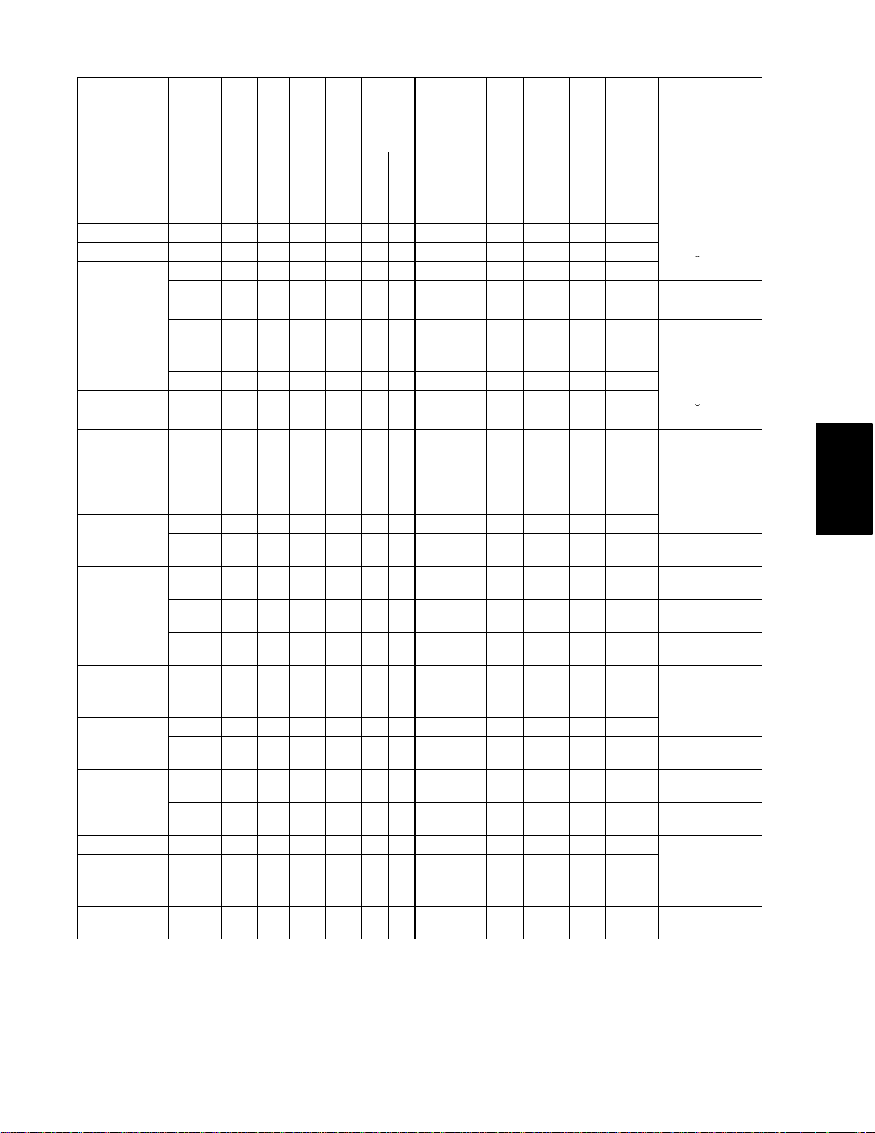
Table 1-1 Model Chart 1-2...................................................
Table 2-1 Safety and Protective Devices 2-19...................................
Table 3-1 Controller Configuration Variables 3-3................................
Table 3-2 Key Pad Function 3-4..............................................
Table 3-3 Controller Function Code Assignments 3-6...........................
Table 3-4 Controller Alarm Indications 3-11.....................................
Table 3-5 Pre-Trip Test Codes 3-19............................................
Table 3-6 DataCORDER Function Code Assignments 3-26.......................
Table 3-7 DataCORDER Alarm Indications 3-28.................................
Table 3-8 DataCORDER Alarm Configurations 3-29..............................
Table 3-9 DataCorder Standard Configuration 3-30..............................
Table 3-10 DataCORDER Pre-Trip Data 3-33....................................
Table 4-1 Electrical Control Positions -- BELOW --10_C(+14_F), or
-- 5 _C(+23_F) optionally 4-14.........................................
Table 4-2 Electrical Control Positions -- ABOVE --10_C(+14_F), or
-- 5 _C(+23_F) optionally 4-15.........................................
Table 6-1 AMBS, DTS, RRS, RTS, SRS and STS Temperature-Resistance Chart 6-32
Table 6-2 Partlow Bulb Temperature-Resistance Chart 6-32.......................
Table 6-3 Recommended Bolt Torque Values 6-33...............................
Table 6-4 Wear Limits For Compressors 6-33...................................
Table 6-5 Compressor Torque Values 6-34......................................
Table 6-6 Temperature-Pressure Chart -- R-134a 6-35............................
viT-268-07
Page 11

SECTION 1
INTRODUCTION
1.1 INTRODUCTION
WARNING
It has been determined that pressurized,
air-rich mixtures of refrigerants and air can
undergo combustion when exposed to an
ignition source.
This manual contains Operating Data, Electrical Data
and Service Instructions for the refrigeration units listed
in Table 1-1. Also, Table 1-1 charts some significant
differences between these models.
NOTE
Beginning with early 1995 production, in
addition to a model number, Carrier Transicold
began usinga parts identification(PID) number
in the format NT0000. In the parts manual, the
PID number is shown in boldface to point out
parts variations within models. The PID
number must be included when ordering and
inquiring about your unit.
The unit, of lightweight aluminum frame construction,
is an all electric, one piece, self-contained cooling and
heating refrigeration unit. The unit is designed to fit in
the frontof a container and to serve as the container front
wall. Forklift pockets are provided for installation and
removal of the unit.
The unit is complete with a charge of R-134a,
compressor lubricating oil (approved POE SW20
compressor oil for R-134a only), mode indicating
lights, and temperature controller, and is ready for
operation upon installation.
Some units are equipped with a two-speed compressor
that is used to enhance power saving.
Some units aredual voltage units designed to operateon
190/230 or 380/460 volts AC, 3-phase, 50-60 hertz
power (refer to section 2.4). Other units are designed to
operate on 380/460 volts AC, 3-phase 50/60 hertz
power only. An external autotransformeris required for
190/230 vac operation (refer to Figure 2-9 and section
2.4).
Operating control power is provided by a control
transformer which steps down the AC supply power
source to 18 and 24 volts AC , single phase control
power.
The temperature Controller/DataCORDER (Micro-Link
2i) is a micropr oce ssor- ba sed controller and a integr ate d
electronic data logging device. Refer to sections 3.1 and
3.3. Once the temperature controller is set at a desired
container temperature, the unit w ill operate automatically
to maintain the desired temperature within very close
limits. The control system automatica lly selects cooling,
holding or heating as necessar y to maintain the de sir ed
temperature within the container.
WARNING
Beware of unannounced start ing of the
evaporator and condenser fans. Do not open
the condenser fan grille before turning
power OFF and disc onnecting power plug.
Some units are equipped with a mechanical temperature
recorder.
Some units may have a TransFRESH controlled
atmosphere system added. Contact TransFRESH
Corporation, P.O. Box 1788, Salinas, CA 93902 for
information on their system.
SECTION 1
1-1 T-268-07
Page 12
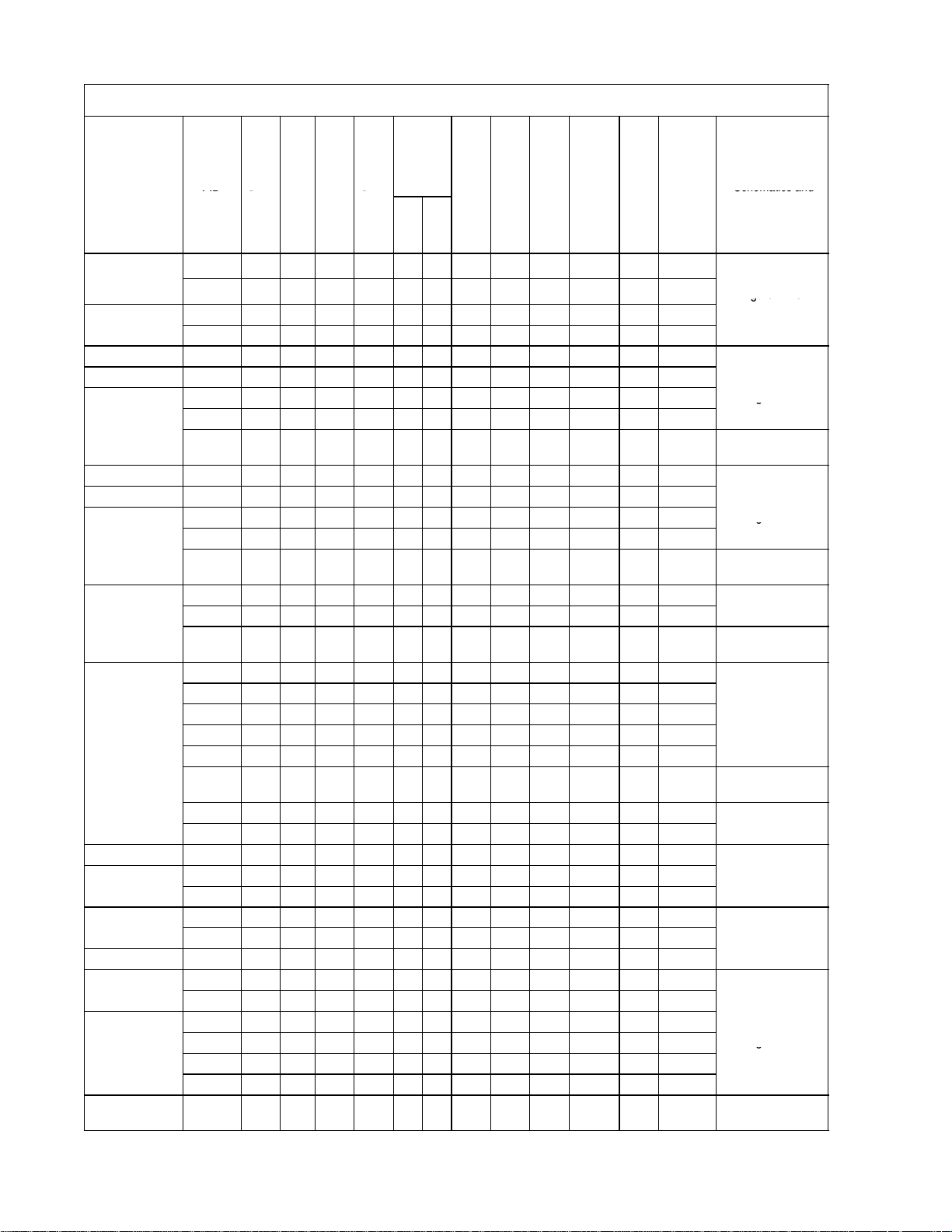
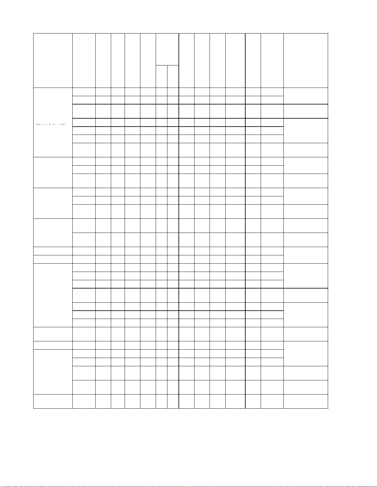
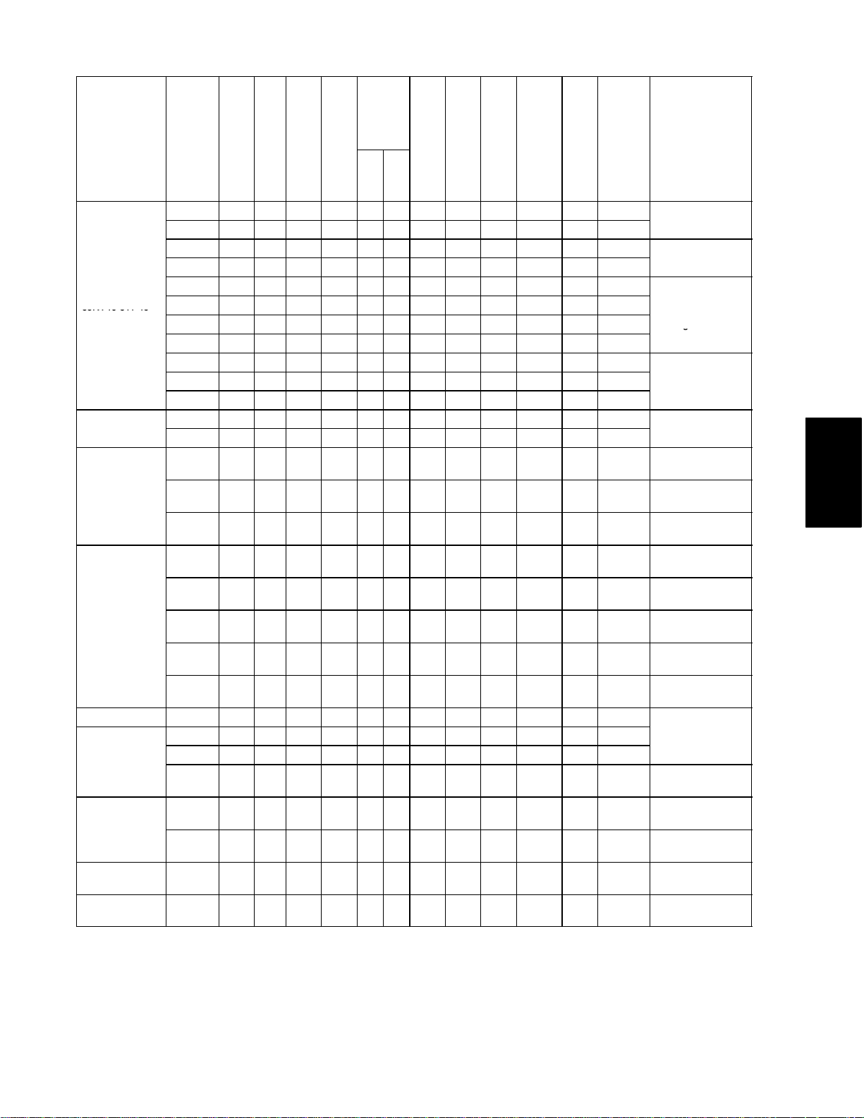
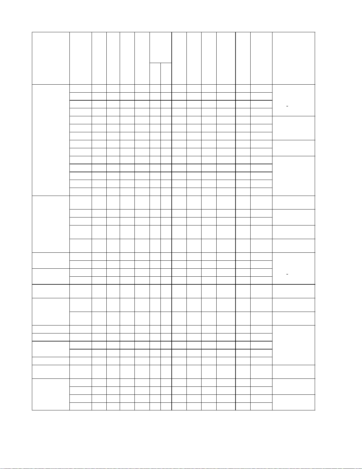
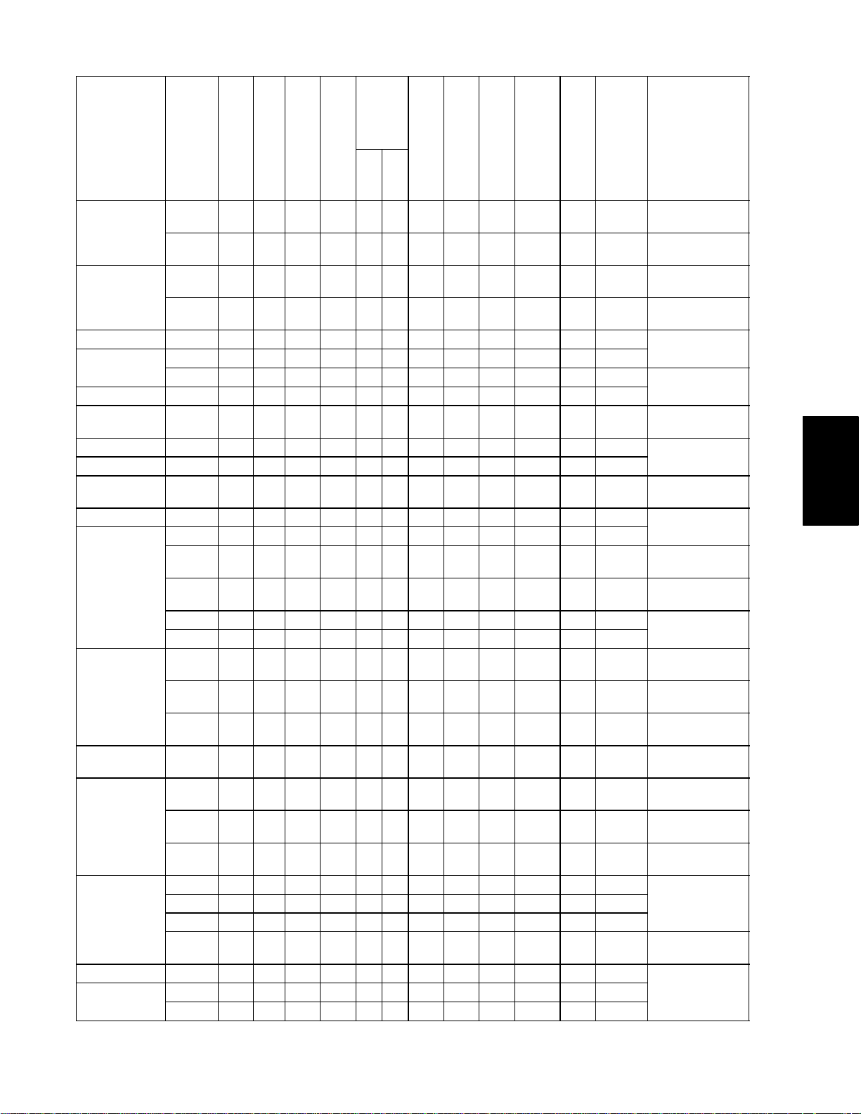
Table 1-1. Model Chart
PID
s
r
n
O
y
s
M
d
Schematicsand
Figure71&
&
Figure7-3
&
g69NT40-511-5
&
Figure7-3
&
g69NT40-511-8
&
Figure7-3
&
69NT4
0-511-9
F
i
4
&
Figure7-19&
F
i
4
F
i
6
&
Figure7-3
&
g
Condenser
MODEL
69NT40-511-1
69NT40-511-2
69NT40-511-3 NT0007 P P --- --- X --- --- X --- --- X ---
69NT40-511-4 NT0037 P X --- P X --- --- P --- --- X ---
69NT40-511-6 NT0013 P P --- --- X --- --- X --- --- --- ---
69NT40-511-7 NT0014 X P --- --- X --- --- X --- --- --- ---
69NT40-511-10
69NT40-511-11 NT0008 P X --- --- --- X A X --- P X ---
69NT40-511-12
69NT40-511-13
69NT40-511-14 NT0018 X P --- --- --- X A X --- X --- ---
69NT40-511-15
69NT40-511-16
69NT40-511-17 NT0043 X P X P X --- --- P --- --- X ---
PID
NT0001 X P X P X --- --- X --- X X ---
NT0062 X P X P X --- --- X --- X X ---
NT0002 X P X X X --- --- X --- X X ---
NT0017 X P X X X --- --- X --- X X ---
NT0011 P X --- P X --- --- P --- --- X ---
NT0038 P X --- P X --- --- P --- --- X ---
NT0099 P X --- P X --- --- P --- --- X ---
NT0005 P X --- P X --- --- P --- --- X ---
NT0037 P X --- P X --- --- P --- --- X ---
NT0094 P X --- P X --- --- P --- --- X ---
NT0064 P P --- P X --- --- P --- --- X ---
NT0089 P P --- P X --- --- P --- --- X ---
NT0152 P P --- P X --- --- P --- --- X ---
NT0024 P X --- P X --- --- P X --- X ---
NT0027 P X --- P X --- --- P X --- X ---
NT0040 P X --- P X --- --- P X --- X ---
NT0041 P X --- P X --- --- P X --- X ---
NT0104 P X --- P X --- --- P X P X ---
NT0112 P X --- P X --- --- P X P X ---
NT0173 P X --- P X --- --- P X --- X ---
NT0209 P X --- P X --- --- P X P X ---
NT0076 P P --- P X --- --- P X --- P ---
NT0082 P P --- P X --- --- P X --- P ---
NT0015 X P --- --- --- X A X --- X --- ---
NT0022 X P --- --- --- X A X --- X --- ---
NT0029 P X --- X X --- --- P --- --- X ---
NT0044 P X --- X X --- --- P --- --- X ---
NT0028 P X --- P X --- --- P --- --- X ---
NT0054 P P --- P X --- --- P --- P X ---
NT0070 P P --- P X --- --- P --- P X ---
NT0083 P P --- P X --- --- P --- P X ---
Cold
USDACTreatm
ent
ressor
nser
-Cooled
Water-CConde
peed
sformer
Tran
Two-SpComp
Coil
Discharge
y Sensor
Option
Suction &
2Row
Pressure
4Row
sFresh
Tran
Humidit
cations
CommunicInterface
odule (CI)
mperature
omiya
SaginoTem peRecor
Partlow TemRecorder
rature
der
Electrical Wiring
Schematics and
Diagrams
Figure 7-1 &
Figure 7-2
Figure 7-3
Figure 7-4
Figure 7-9 &
Figure 7-10
Figure 7-3
Figure 7-4
Figure 7-9 &
Figure 7-10
Figure 7-3
Figure 7-4
Figure 7-9 &
Figure 7-10
Figure 7-3 &
gure7-
Figure 7-9 &
Figure 7-10
Figure 7-19
Figure 7-20
Figure 7-3 &
gure7-
Figure 7-5 &
gure7-
Figure 7-3
Figure 7-4
Figure 7-1 &
Figure 7-2
1-2T-268-07
Page 13
Condenser
&
Figure7-3
&
g
&
Figure7-9
&
&
Figure7-3
&
g
&
Figure7-3
&
&
Figure7-3
&
&
Figure7-3
&
MODEL
MODEL
69NT40-511-18 NT0035 P X --- P X --- A P --- X X ---
69NT40-511-19 NT0037 P X --- P X --- --- P --- --- X ---
69NT40-511-21 NT0055 P X --- P X --- --- P X --- X ---
69NT40-511-22
69NT40-511-23
69NT40-511-24 NT0051 P P --- P X --- --- P --- P P ---
69NT40-511-25 NT0053 P P --- P X --- --- P --- --- X ---
69NT40-511-26
69NT40-511-27 NT0056 X X --- P --- X --- P --- P X ---
69NT40-511-28
69NT40-511-29
69NT40-511-30 NT0060 X --- X --- --- X A X --- X --- ---
69NT40-511-31 NT0061 P X --- P X --- --- X --- --- X ---
69NT40-511-32
69NT40-511-33
69NT40-511-34 NT0065 P P --- P X --- B P --- --- X ---
69NT40-511-35 NT0071 X P --- P --- X --- P --- P X ---
69NT40-511-36 NT0072 X --- --- --- --- X A X --- X --- ---
69NT40-511-37 NT0073 X --- --- P X --- B X X --- X ---
PID
PID
Transformer
Transformer
Two-Speed
Compressor
Two-Speed
Compressor
Water-Cooled
Condenser
Water-Cooled
USDA Cold
Treatment
USDA Cold
Treatment
NT0046 P X --- P --- X A P --- --- X ---
NT0121 P X --- P --- X A P --- --- X ---
NT0139 P X --- P --- X A P --- --- X ---
NT0252 P X --- P --- X A P --- --- X ---
NT0050 P X --- P X --- --- P --- P X ---
NT0069 P X --- P X --- --- P --- P X ---
NT0047 P P X P X --- --- P P P P ---
NT0175 P P X P X --- --- P P P P ---
NT0057 P P --- P X --- --- P X --- X ---
NT0132 P P --- P X --- --- P X P X ---
NT0059 P P --- X X --- --- X --- --- X ---
NT0219 P P --- X X --- --- X --- --- X ---
NT0343 P P --- X X --- --- X --- P X ---
NT0067 P X --- P X --- --- P --- P P ---
NT0097 P X --- P X --- --- P --- P P ---
NT0068 P X --- P X --- --- P X P --- ---
NT0239 P X --- P X --- --- P X P P ---
Condenser
Coil
TransFresh
TransFresh
Humidity Sensor
Humidity Sensor
Suction & Discharge
Pressure Option
Suction & Discharge
Pressure Option
4Row
2Row
Communications
Communications
Interface Module (CI)
Interface Module (CI)
Saginomiya
Saginomiya
Partlow Temperature
Recorder
Partlow Temperature
Recorder
Temperature
Recorder
Temperature
Recorder
Electrical Wiring
Electrical Wiring
Schematics and
Schematics and
Diagrams
Diagrams
Figure 7-3
Figure 7-4
Figure 7-9
Figure 7-10
Figure7-41&
Figure 7-42
Figure 7-3
Figure 7-4
Figure 7-1 &
Figure 7-2
Figure7-21&
Figure 7-22
Figure 7-3
Figure 7-4
Figure 7-9 &
Figure 7-10
Figure 7-3 &
Figure 7-4
Figure7-19&
Figure 7-20
Figure7-57&
Figure 7-58
Figure 7-7 &
Figure 7-8
Figure 7-3
Figure 7-4
Figure 7-9 &
Figure 7-10
Figure 7-3 &
Figure 7-4
Figure7-41&
Figure 7-42
Figure 7-3
Figure 7-4
Figure 7-5 &
Figure 7-6
Figure 7-3 &
Figure 7-4
SECTION 1
1-3 T-268-07
Page 14
Condenser
&
Figure7-11&
69NT4051138
F
i
4
8
&
Figure7-3
&
69NT4
0-511-3
9
&
Figure7-3
&
69NT4
0-511-4
0
&
Figure7-3
&
F
i
1
0
F
i
4
2
F
i
1
0
MODEL
MODEL
69NT40-511-38
69NT40-511-41
69NT40-511-42 NT0088 P P --- P X --- --- P --- --- P ---
69NT40-511-43 NT0081 P P --- P X --- --- P X --- --- ---
69NT40-511-44
69NT40-511-45 NT0092 P P --- P X --- --- P X --- P ---
69NT40-511-46 NT0110 P X --- P --- X --- P --- P X ---
69NT40-511-47
69NT40-511-48 NT0101 P P --- P --- X --- P --- P X ---
PID
PID
Transformer
Transformer
Two-Speed
Compressor
Two-Speed
Compressor
Water-Cooled
Condenser
Water-Cooled
USDA Cold
Treatment
USDA Cold
Treatment
NT0074 X --- --- --- --- X A X --- X --- ---
NT0135 X --- --- --- --- X A X --- X --- ---
NT0208 X --- --- --- --- X A X --- X --- ---
NT0246 X --- --- --- --- X A X --- X --- ---
NT0253 X --- --- --- --- X A X --- X --- ---
NT0267 X --- --- --- --- X A X --- X --- ---
NT0307 X --- --- --- --- X A X --- X --- ---
NT0078 X P --- X X --- --- X --- X X ---
NT0084 X P --- X X --- --- X --- X X ---
NT0095 X P --- X X --- --- X --- X X ---
NT0079 X P --- P X --- --- X --- X X ---
NT0085 X P --- P X --- --- X --- X X ---
NT0096 X P --- P X --- --- X --- X X ---
NT0080 P P --- P X --- --- P --- P --- ---
NT0090 P P --- P X --- --- P --- P --- ---
NT0091 X X --- --- --- X A X --- P X ---
NT0102 P X --- --- --- X A X --- P X ---
NT0137 P X --- --- --- X A X --- P X ---
NT0185 P X --- --- --- X A X --- P X ---
NT0213 P X --- --- --- X A X --- P --- X
NT0244 P X --- --- --- X A X --- P --- X
NT0266 P X --- --- --- X A X --- P --- X
NT0098 P X --- X X --- B P --- P --- X
NT0124 P X --- X X --- B P --- P --- X
NT0146 P X --- X X --- B P --- P --- X
NT0186 P X --- X X --- B P --- P --- X
Condenser
Coil
TransFresh
TransFresh
Humidity Sensor
Humidity Sensor
Suction & Discharge
Pressure Option
Suction & Discharge
Pressure Option
4Row
2Row
Communications
Communications
Interface Module (CI)
Interface Module (CI)
Saginomiya
Saginomiya
Partlow Temperature
Recorder
Partlow Temperature
Recorder
Temperature
Recorder
Temperature
Recorder
Electrical Wiring
Electrical Wiring
Schematics and
Schematics and
Diagrams
Diagrams
Figure 7-11
Figure 7-12
Figure7-31&
Figure 7-32
Figure7-47&
gure7-
Figure7-63&
Figure 7-64
Figure 7-3
Figure 7-4
Figure 7-9 &
Figure 7-10
Figure 7-3
Figure 7-4
Figure 7-9 &
Figure 7-10
Figure 7-3 &
Figure 7-4
Figure7-65&
Figure 7-66
Figure 7-3
Figure 7-4
Figure 7-9 &
gure7-
Figure7-19&
Figure 7-20
Figure7-41&
gure7-
Figure 7-3 &
Figure 7-4
Figure 7-9 &
gure7-
Figure7-23&
Figure 7-24
Figure7-19&
Figure 7-20
Figure 7-3 &
Figure 7-4
1-4T-268-07
Page 15
Condenser
&
Figure7-9
&
&
Figure7-19&
&
69NT4051149
Figure7-41&
g
F
i
5
8
&
Figure7-9
&
F
i
1
0
69NT4
0-511-5
4
MODEL
MODEL
69NT40-511-49
69NT40-511-50
69NT40-511-51
69NT40-511-52
69NT40-511-53 NT0113 P P --- P X --- --- P X P --- ---
69NT40-511-55
69NT40-511-56 NT0242 P P --- P --- X --- P X P X ---
69NT40-511-57 NT0156 P X --- P X --- --- P --- P X ---
PID
PID
Transformer
Transformer
Two-Speed
Compressor
Two-Speed
Compressor
Water-Cooled
Condenser
Water-Cooled
USDA Cold
Treatment
USDA Cold
Treatment
NT0103 P P --- P X --- --- P --- P X ---
NT0134 P P --- P X --- --- P --- P X ---
NT0184 P P --- P X --- --- P --- P X ---
NT0216 P P --- P X --- --- P --- P X ---
NT0268 P P --- P X --- --- P --- P X ---
NT0282 P P --- P X --- --- P --- P X ---
NT0283 P P --- P X --- --- P --- P --- X
NT0303 P P --- P X --- --- P --- --- --- X
NT0308 P P --- P X --- --- P --- P X ---
NT0341 P P --- P X --- --- P --- P --- X
NT0345 P P --- P --- X --- P --- P X ---
NT0106 X X --- P X --- --- X --- X --- X
NT0178 X X --- P X --- --- X --- X --- X
NT0107 X X --- P --- X A P --- --- X ---
NT0207 X X --- P --- X A P --- --- X ---
NT0417 X P --- P --- X --- P --- P --- ---
NT0109 P X --- P X --- --- P --- P X ---
NT0111 P X --- P X --- --- P --- P X ---
NT0133 P X --- P X --- --- P --- P X ---
NT0162 P X --- P X --- --- P --- P X ---
NT0225 P X --- P X --- --- P --- P X ---
NT0118 P P --- P X --- --- P --- P X ---
NT0136 P P --- P X --- --- P --- P X ---
NT0215 P P --- P X --- --- P --- P X ---
NT0120 P --- --- --- --- X --- P --- --- X ---
NT0188 P --- --- --- --- X --- P --- --- X ---
Condenser
Coil
TransFresh
TransFresh
Humidity Sensor
Humidity Sensor
Suction & Discharge
Pressure Option
Suction & Discharge
Pressure Option
4Row
2Row
Communications
Communications
Interface Module (CI)
Interface Module (CI)
Saginomiya
Saginomiya
Partlow Temperature
Recorder
Partlow Temperature
Recorder
Temperature
Recorder
Temperature
Recorder
Electrical Wiring
Electrical Wiring
Schematics and
Schematics and
Diagrams
Diagrams
Figure 7-9
Figure 7-10
Figure 7-19
Figure 7-20
Figure 7-41
Figure 7-42
Figure7-57&
gure7-
Figure 7-9
Figure 7-10
Figure7-13&
Figure 7-14
Figure7-45&
Figure 7-46
Figure7-67&
Figure 7-68
Figure 7-9 &
Figure 7-10
Figure 7-3 &
Figure 7-4
Figure 7-9 &
Figure 7-10
Figure7-19&
Figure 7-20
Figure7-41&
Figure 7-42
Figure 7-9 &
gure7-
Figure7-41&
Figure 7-42
Figure 7-9 &
Figure 7-10
Figure7-19&
Figure 7-20
Figure7-41&
Figure 7-42
Figure 7-9 &
Figure 7-10
SECTION 1
1-5 T-268-07
Page 16
Condenser
&
Figure7-9
&
g
F
i
2
0
&
Figure7-41&
F
i
5
8
&
Figure7-19&
69NT4
0-511-5
9
&
Figure7-9
&
g
F
i
1
0
&
Figure7-41&
&
Figure7-57&
MODEL
MODEL
69NT40-511-58
69NT40-511-60
69NT40-511-61
69NT40-511-62 NT0127 P P --- P X --- --- P --- X X ---
69NT40-511-63
69NT40-511-64 NT0131 P X --- --- --- X A X X P X ---
69NT40-511-65 NT0119 P X --- X X --- --- P --- P X ---
69NT40-511-66
69NT40-511-67 NT0143 P P --- P X --- --- P --- --- P ---
69NT40-511-69 NT0177 P P --- P X --- --- P --- P P ---
69NT40-511-70
PID
PID
Transformer
Transformer
Two-Speed
Compressor
Two-Speed
Compressor
Water-Cooled
Condenser
Water-Cooled
USDA Cold
Treatment
USDA Cold
Treatment
NT0105 P X --- P X --- --- P --- P X ---
NT0122 P X --- P X --- --- P --- P X ---
NT0138 P X --- P X --- --- P --- P X ---
NT0141 P X --- P X --- --- P --- P X ---
NT0160 P X --- P X --- --- P --- P X ---
NT0161 P X --- P X --- --- P --- P X ---
NT0189 P X --- P X --- --- P --- P X ---
NT0240 P X --- P X --- --- P --- P X ---
NT0269 P X --- P X --- --- P --- P X ---
NT0309 P X --- P X --- --- P --- P X ---
NT0340 P X --- P X --- --- P X P P ---
NT0386 P X --- P X --- --- P X P X ---
NT0418 P X --- P X --- --- P --- P X ---
NT0428 P X --- P X --- --- P --- P --- X
NT0167 P P --- P X --- --- P --- P X ---
NT0174 P P --- P X --- --- P --- P X ---
NT0211 P P --- P X --- --- P --- P X ---
NT0272 P P --- P X --- --- P --- P X ---
NT0312 P P --- P X --- --- P --- P X ---
NT0125 X X --- P --- X A P --- --- X ---
NT0153 X X --- P --- X A P --- --- X ---
NT0126 X X --- P X --- A P --- --- X ---
NT0154 X X --- P X --- A P --- --- X ---
NT0140 X --- --- P --- X --- X X X --- ---
NT0192 X --- --- P --- X --- X X X --- ---
NT0129 P X --- X X --- --- P --- P X ---
NT0147 P X --- X X --- --- P --- P X ---
NT0241 P X --- P --- X --- X X P X ---
NT0271 P X --- P --- X --- X X P X ---
NT0311 P X --- P --- X --- X X P X ---
NT0353 P X --- P --- X --- X X P X ---
Condenser
Coil
TransFresh
TransFresh
Humidity Sensor
Humidity Sensor
Suction & Discharge
Pressure Option
Suction & Discharge
Pressure Option
4Row
2Row
Communications
Communications
Interface Module (CI)
Interface Module (CI)
Saginomiya
Saginomiya
Partlow Temperature
Recorder
Partlow Temperature
Recorder
Temperature
Recorder
Temperature
Recorder
Electrical Wiring
Electrical Wiring
Schematics and
Schematics and
Diagrams
Diagrams
Figure 7-9
Figure 7-10
Figure7-19&
gure7-
Figure 7-41
Figure 7-42
Figure7-57&
gure7-
Figure 7-9 &
Figure 7-10
Figure 7-19
Figure 7-20
Figure7-41&
Figure 7-42
Figure7-57&
Figure 7-58
Figure 7-9
Figure 7-10
Figure7-17&
Figure 7-18
Figure 7-9 &
Figure 7-10
Figure7-19&
Figure 7-20
Figure 7-9 &
gure7-
Figure7-19&
Figure 7-20
Figure 7-41
Figure 7-42
Figure 7-57
Figure 7-58
1-6T-268-07
Page 17
Condenser
&
Figure7-9
&
&
Figure7-19&
&
Figure7-9
&
&
Figure7-9
&
&
Figure7-41&
F
i
3
2
F
i
4
2
MODEL
MODEL
69NT40-511-71
69NT40-511-72
69NT40-511-73 NT0158 P P --- P --- X --- P --- P X ---
69NT40-511-74
69NT40-511-75 NT0163 X P --- P --- X A X --- P X ---
69NT40-511-76 NT0169 P X X P X --- B P --- P --- X
69NT40-511-77 NT0176 P X --- P X --- B P --- P X ---
69NT40-511-78 NT0182 P X --- P X --- --- X --- P X ---
69NT40-511-79 NT0190 --- X --- P X --- B P --- --- --- X
69NT40-511-80 NT0165 P P --- P X --- --- P --- P P ---
69NT40-511-81
69NT40-511-82
69NT40-511-83 NT0210 P P --- P --- X --- X --- P X ---
69NT40-511-84
69NT40-511-85
69NT40-511-87 NT0214 P P --- P X --- B P X P --- X
69NT40-511-89
PID
PID
Transformer
Transformer
Two-Speed
Compressor
Two-Speed
Compressor
Water-Cooled
Condenser
Water-Cooled
USDA Cold
Treatment
USDA Cold
Treatment
NT0166 P X --- P X --- --- P X P X ---
NT0235 P X --- P X --- --- P X P X ---
NT0157 P X --- P X --- --- P X P X ---
NT0200 P X --- --- X --- --- P X P X ---
NT0159 P P --- P X --- --- P --- P X ---
NT0223 P P --- P X --- --- P --- P X ---
NT0151 P X --- P X --- --- P --- P X ---
NT0168 P X --- P X --- --- P --- P X ---
NT0180 P X --- P X --- --- P --- P X ---
NT0236 P X --- P X --- --- P --- P X ---
NT0258 P X --- P X --- --- P --- P X ---
NT0187 P X --- P X --- A P X P X ---
NT0198 P X --- P X --- A P X P X ---
NT0199 P X --- P X --- A X X P X ---
NT0191 --- --- --- X --- X --- P --- P P ---
NT0201 --- --- --- X --- X --- P --- P --- ---
NT0334 --- --- --- X --- X --- P --- P --- ---
NT0183 X --- --- X --- X A P --- X --- ---
NT0226 X --- --- X --- X A X --- X --- ---
NT0280 X --- --- X --- X A X --- X --- ---
NT0317 X --- --- X --- X A X --- X --- ---
NT0212 X P --- P X --- --- P --- P P ---
NT0243 X P --- P X --- --- P --- P P ---
Condenser
Coil
TransFresh
TransFresh
Humidity Sensor
Humidity Sensor
Suction & Discharge
Pressure Option
Suction & Discharge
Pressure Option
4Row
2Row
Communications
Communications
Interface Module (CI)
Interface Module (CI)
Saginomiya
Saginomiya
Partlow Temperature
Recorder
Partlow Temperature
Recorder
Temperature
Recorder
Temperature
Recorder
Electrical Wiring
Electrical Wiring
Schematics and
Schematics and
Diagrams
Diagrams
Figure7-19&
Figure 7-20
Figure7-41&
Figure 7-42
Figure7-25&
Figure 7-26
Figure7-33&
Figure 7-34
Figure 7-9
Figure 7-10
Figure 7-19
Figure 7-20
Figure7-15&
Figure 7-16
Figure 7-9
Figure 7-10
Figure7-39&
Figure 7-40
Figure 7-9
Figure 7-10
Figure7-19&
Figure 7-20
Figure 7-9 &
Figure 7-10
Figure 7-41
Figure 7-42
Figure7-31&
Figure 7-32
Figure7-27&
Figure 7-28
Figure7-35&
Figure 7-36
Figure7-43&
Figure 7-44
Figure7-19&
Figure 7-20
Figure7-41&
Figure 7-42
Figure7-57&
Figure 7-58
Figure7-31&
gure7-
Figure7-55&
Figure 7-56
Figure7-41&
gure7-
SECTION 1
1-7 T-268-07
Page 18
Condenser
&
Figure7-51&
&
Figure7-29&
69NT4051194
g
69NT40-511-95
F
i
5
8
F
i
4
2
F
i
4
2
69NT4
0-511-101
&
Figure7-41&
g
&
Figure7-57&
MODEL
MODEL
69NT40-511-90 NT0222 P P --- P X --- --- P --- P X ---
69NT40-511-91
69NT40-511-92 NT0218 P X --- --- --- X A X X P --- X
69NT40-511-93 NT0197 X --- --- P --- X --- X X X --- ---
69NT40-511-94
69NT40-511-95
69NT40-511-96 NT0224 P X --- P --- X B P --- --- --- X
69NT40-511-97 NT0228 P P --- P --- X --- P --- P X ---
69NT40-511-98 NT0297 P X --- P X --- --- X --- P --- X
69NT40-511-99 NT0245 X P --- P X --- --- X --- X --- X
69NT40-511-100 NT0247 P X --- P --- X --- X --- P X ---
69NT40-511-102
69NT40-511-103 NT0259 P P --- P --- X --- X X P P ---
69NT40-511-104 NT0260 P X --- P X --- --- X --- --- X ---
69NT40-511-105 NT0274 X X --- P --- X A P --- --- X ---
69NT40-511-106
PID
PID
Transformer
Transformer
Two-Speed
Compressor
Two-Speed
Compressor
Water-Cooled
Condenser
Water-Cooled
USDA Cold
Treatment
USDA Cold
Treatment
NT0202 --- --- --- P --- X --- P --- P --- ---
NT0238 --- --- --- P --- X --- P --- P --- ---
NT0278 --- --- --- P --- X --- P --- P --- ---
NT0318 --- --- --- X --- X --- P --- P --- ---
NT0204 X --- --- P --- X --- X X X --- ---
NT0262 X --- --- P --- X --- X --- X --- ---
NT0265 X --- --- P --- X --- X --- X --- ---
NT0220 P P --- P --- X --- P --- P P ---
NT0322 P P --- P --- X --- P --- P X ---
NT0344 P P --- P --- X --- P --- P X ---
NT0365 P P --- P --- X --- P --- X P ---
NT0285 P P --- P --- X --- P --- P X ---
NT0322 P P --- P --- X --- P --- P X ---
NT0250 --- X --- P X --- B P --- --- --- X
NT0298 --- X --- P X --- B P --- --- --- X
NT0333 --- X --- P X --- B P --- --- --- X
NT0251 P P --- P X --- --- P --- P P ---
NT0254 P P --- P X --- --- P --- P P ---
NT0263 X P --- P X --- --- X --- P X ---
NT0414 X P --- P --- X --- X --- P X ---
NT0415 X P --- P --- X --- X X P X ---
Condenser
Coil
TransFresh
TransFresh
Humidity Sensor
Humidity Sensor
Suction & Discharge
Pressure Option
Suction & Discharge
Pressure Option
4Row
2Row
Communications
Communications
Interface Module (CI)
Interface Module (CI)
Saginomiya
Saginomiya
Partlow Temperature
Recorder
Partlow Temperature
Recorder
Temperature
Recorder
Temperature
Recorder
Electrical Wiring
Electrical Wiring
Schematics and
Schematics and
Diagrams
Diagrams
Figure7-19&
Figure 7-20
Figure7-37&
Figure 7-38
Figure 7-51
Figure 7-52
Figure7-61&
Figure 7-62
Figure7-41&
Figure 7-42
Figure 7-29
Figure 7-30
Figure7-19&
Figure 7-20
Figure7-57&
gure7-
Figure7-41&
gure7-
Figure7-57&
Figure 7-58
Figure7-41&
gure7-
Figure7-57&
Figure 7-58
Figure 7-41
Figure 7-42
Figure7-53&
Figure 7-54
Figure7-41&
Figure 7-42
Figure 7-57
Figure 7-58
1-8T-268-07
Page 19
Condenser
&
Figure7-49&
&
Figure7-59&
g
&
Figure7-41&
&
Figure7-41&
g
69NT4
0-511-111
&
Figure7-41&
&
69NT4051111
4
Figure7-57&
g
&
Figure7-41&
g
&
Figure7-57&
g
MODEL
MODEL
69NT40-511-107
69NT40-511-108 NT0264 P P --- P --- X --- X X P X ---
69NT40-511-109 NT0284 P P --- P --- X --- X X P X ---
69NT40-511-110
69NT40-511-112
69NT40-511-113 NT0294 P X --- X --- X --- X X P X ---
69NT40-511-114
69NT40-511-115
69NT40-511-116 NT0302 X P --- P X --- --- P --- P --- ---
69NT40-511-117 NT0348 X P --- P --- X --- X --- P X ---
69NT40-511-118
69NT40-511-119 NT0389 P X --- P --- X --- P --- P X ---
69NT40-511-120 NT0410 --- P --- P X --- --- X --- --- --- ---
69NT40-521-10 NT0108 X X --- P X --- --- X --- X --- X
PID
PID
Transformer
Transformer
Two-Speed
Compressor
Two-Speed
Compressor
Water-Cooled
Condenser
Water-Cooled
USDA Cold
Treatment
USDA Cold
Treatment
NT0275 P X --- P --- X A X X P X ---
NT0277 P X --- P --- X A X X P X ---
NT0315 P X --- P --- X A X X P X ---
NT0354 P X --- P --- X A X X P X ---
NT0381 P X --- P --- X X X X P X ---
NT0385 P X --- P --- X X X X P X ---
NT0288 X X --- P --- X --- X X P X ---
NT0296 X X --- P --- X --- X X P --- X
NT0347 X P --- P --- X --- X X P X ---
NT0349 X X --- P --- X --- X X P X ---
NT0286 X X --- X --- X --- X X P X ---
NT0295 X X --- X --- X --- X X P --- X
NT0429 X P --- X --- X --- X --- P X ---
NT0289 P P --- P X --- --- P --- --- X ---
NT0325 P P --- P X --- --- P --- --- X ---
NT0290 P P --- P --- X --- X X P X ---
NTO326 P P --- P --- X --- X X P X ---
NT0335 P --- --- --- --- X --- X --- P X ---
NT0336 P --- --- --- --- X --- X --- X X ---
NT0358 P P --- P --- X --- X X P X ---
NT0299 P X --- P --- X A X --- P X ---
NT0300 P X --- P --- X --- X --- P X ---
NT0387 P P --- P --- X --- P --- P X ---
NT0388 P P --- P --- X --- P --- P X ---
Condenser
Coil
TransFresh
TransFresh
Humidity Sensor
Humidity Sensor
Suction & Discharge
Pressure Option
Suction & Discharge
Pressure Option
4Row
2Row
Communications
Communications
Interface Module (CI)
Interface Module (CI)
Saginomiya
Saginomiya
Partlow Temperature
Recorder
Partlow Temperature
Recorder
Temperature
Recorder
Temperature
Recorder
Electrical Wiring
Electrical Wiring
Schematics and
Schematics and
Diagrams
Diagrams
Figure 7-49
Figure 7-50
Figure 7-59
Figure 7-60
Figure 7-41
Figure 7-42
Figure 7-41
Figure 7-42
Figure7-57&
Figure 7-58
Figure7-41&
Figure 7-42
Figure7-57&
Figure 7-58
Figure 7-41
Figure 7-42
Figure 7-57
Figure 7-58
Figure 7-41
Figure 7-42
Figure 7-57
Figure 7-58
Figure 7-9 &
Figure 7-10
SECTION 1
A -- Factory Installed Pressure Gauges
B -- Factory Installed Pressure Transducers.
P -- Provision.
X -- Features that apply to model.
1-9 T-268-07
Page 20
SECTION 2
DESCRIPTION
2.1 GENERAL DESCRIPTION
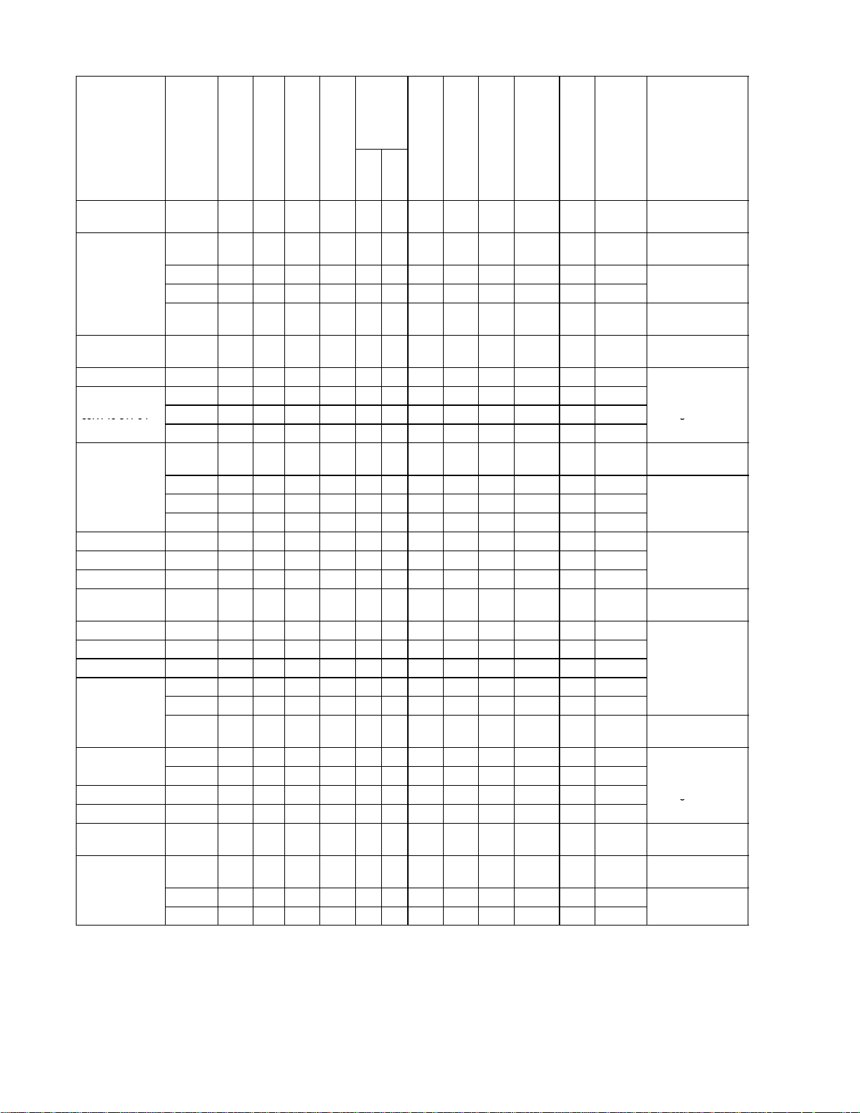
a. Refrigeration Unit -- Front Section
The front section of the refrigeration unit shows access
to most parts of t he unit (i.e., compressor, condenser,
receiver, etc.), which will be discussed in more detail of
the following sections in 2.1. The upper access panels
9
8
allow front entry into the evaporator section, and the
center access panel allows access to the thermostatic
expansion valve and evaporator coil heaters. The unit
model number, serial number and parts identification
number willbe found on the frontof the unit to theleft of
the compressor.
10
1
2
3
7
6
5
4
1. Access Panel (For Evap. Fan Motor #1)
2. Access Panel (For Heater & Thermostatic
Expansion Valve)
3. Fork Lift Pockets
4. Unit Serial Number, Model Number and Parts
Identification Number (PID) Plate
5. TransFRESH Communications Connector (TCC)
-- Optional
SECTION 2
6. Interrogator Connector (Also see Figure 2-7)
7. Mechanical Recording Thermometer -- Optional -(Partlow or Saginomiya)
8. Lower Fresh Air Makeup Vent or Blank Plate -Optional
9. Upper Fresh Air Makeup Vent and Access Panel
(For Evap. Fan Motor #2)
10. Return Air Thermometer Port -- Optional
Figure 2-1. Refrigeration Unit -- Front
2-1 T-268-07
Page 21

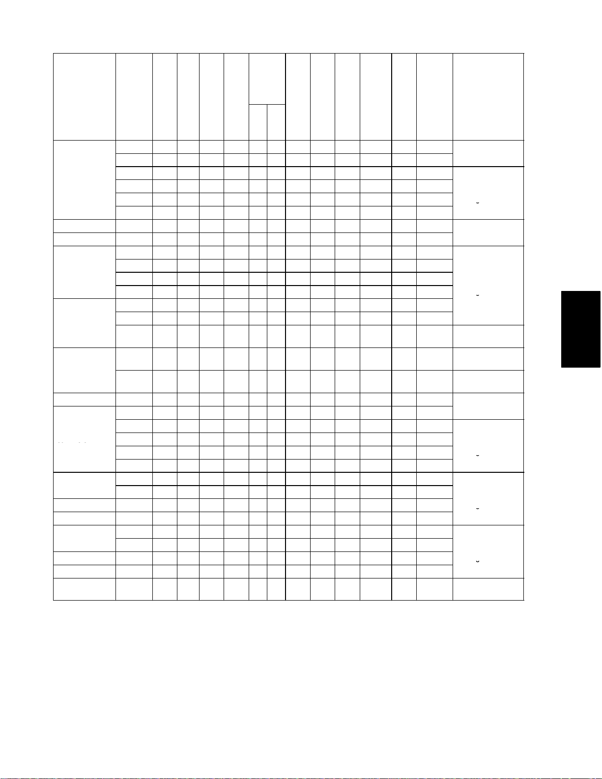
b. Evaporator Section
The evaporator section contains the optional
mechanical temperature recording bulb, return recorder
sensor (RRS), return temperature sensor (RTS),
thermostatic expansion valve, dual-speed evaporator
fan motors and fans (2), evaporator coil and heaters,
drain pan and heater, defrost termination sensor, heat
termination thermostat, and heat exchanger. See
Figure 2-2 and Figure 2-5 for sensor locations.
When transporting perishable (chilled) commodities,
the fan motors will normally be in high speed above
-- 1 0 _C(+14_ F), or --5_C(+23_F) optiona lly.
The evaporator coil heaters are accessible by removing
the front lower access panel. The defrost termination
sensor (DTS) is located on the coil center tube sheet and
may be serviced by removing the upper rear panel, or by
removing the left front upper access panel,
disconnecting the evaporator fan connector and
reaching through the access panel opening.
The evaporator fans circulate air throughout the
container by pulling air in the top of the refrigeration
unit, directing the air through the evaporator coil where
it is either heated or cooled, and discharging t he air
through the bottom of the refrigeration unit into the
container.
WARNING
Before servicing unit, make sure the unit
circuit breakers (CB-1 & CB-2) and the
start-stop switch (ST) are in the OFF
position. Also disconnect power plug and
cable.
2-2T-268-07
Page 22
4
3
8
7
5
2
19
18
17
16
15
14
1
12
9
10
6
11
SECTION 2
13
1. Evaporator Fan Motor #1 (EM1)
2. Humidity Sensor (HS) -- Optional
3. Return Recorder Sensor (RRS)
4. Return Temperature Sensor (RTS)
5. Mechanical Recording Thermometer Bulb
6. Mechanical Recording Thermometer Bulb -Used on PID NT0073
7. Evaporator Fan Motor #2 (EM2)
8. Defrost Termination Sensor (DTS)
9. Heater Termination Thermostat (HTT)
Figure 2-2. Refrigeration Unit -- Rear (Panels Removed)
10. Evaporator Coil
11. Drain Pan Heater (DPH)
12. Thermostatic Expansion Valve
13. Heat Exchanger
14. Interrogator Receptacle (IC) -- Optional
15. USDA Probe Receptacle (PR2) -- Optional
16. USDA Probe Receptacle (PR1) -- Optional
17. USDA Probe Receptacle (PR3) -- Optional
18. Cargo Probe Receptacle (PR4) -- Optional
19. Evaporator Coil Heaters
2-3 T-268-07
Page 23
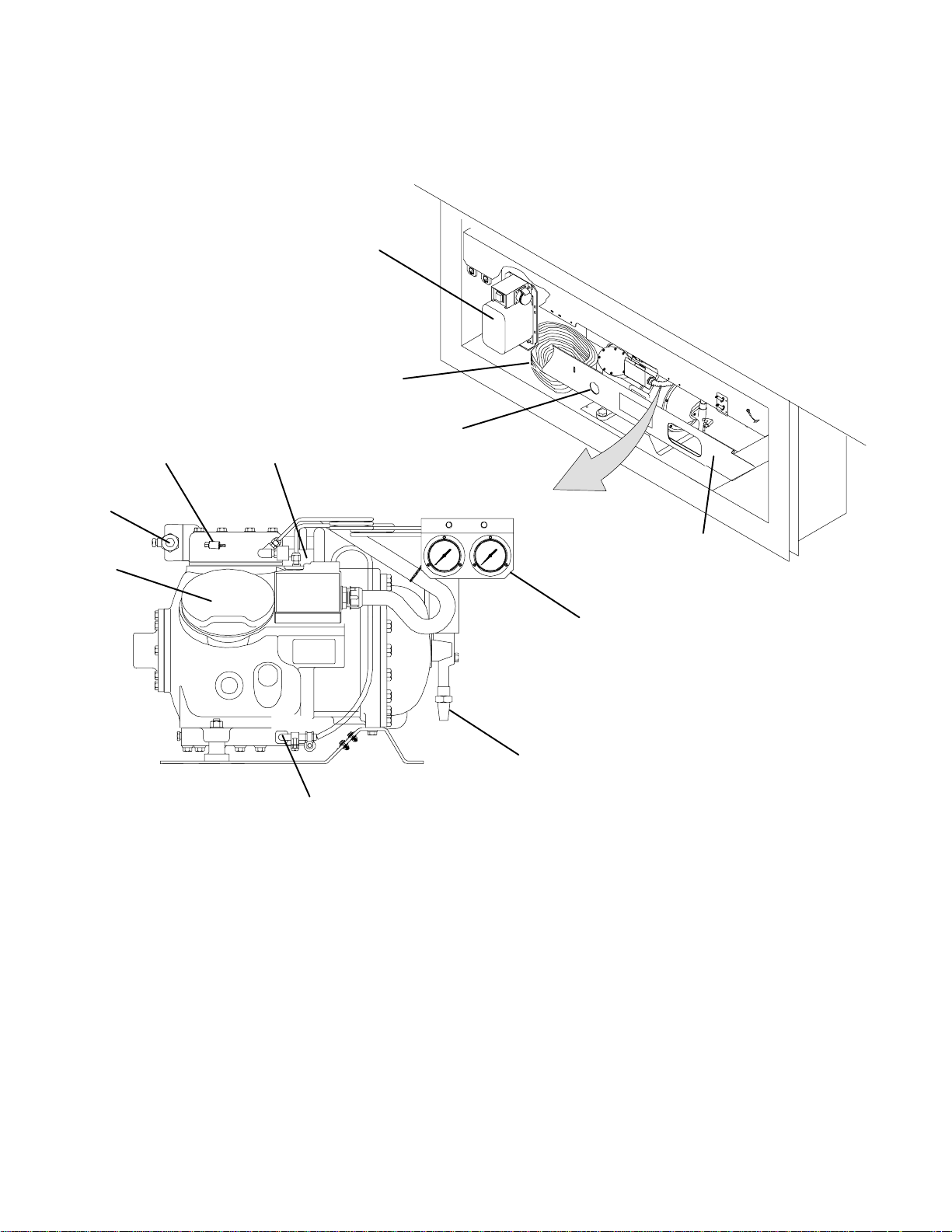
c. Compressor Section
The compressorsection includes thecompressor, power
cable storagecompartment, and an optionaltransformer
(refer to Table 1-1 and Figure 2-9), which is located to
1
2
10
9
11
the left of the compressor.
This section also contains the optional
discharge/suction pressure transducers.
3
8
7
1. Power Autotransformer -- Optional
2. Power Cables and Plug
3. Compressor Sight Glass View Port
4. Compressor Guard
5. Suction/Discharge Pressure Gauges -- Optional
6. Suction Service Valve
Figure 2-3. Compressor Section
4
5
6
7. Compressor Crankcase Heater (CCH) -- Optional
8. Compressor Motor (CP)
9. Discharge Service Valve
10. Discharge Pressure Transducer (DPT) -- Optional
11. Suction Pressure Transducer (SPT) -- Optional
2-4T-268-07
Page 24
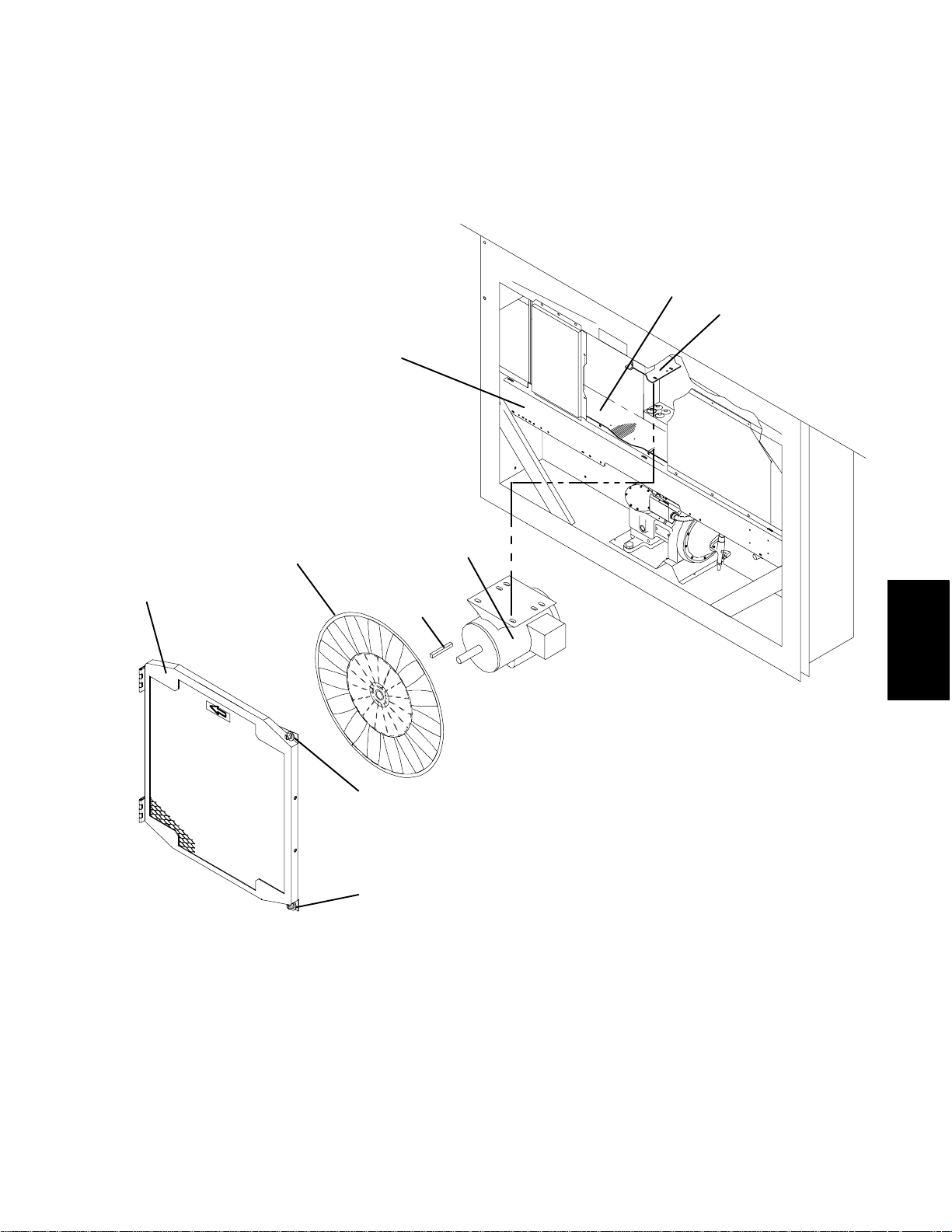
d. Condenser Section
The condensing section consists of a condenser fan
motor, a condenser fan and an air-cooledcondenser coil.
6
When the unit is operating, air is pulled in the bottom of
the coil and discharged horizontally out through the
front of the condenser fan grille.
7
8
3
1
1. Grille and Venturi Assembly
2. Retaining Screw
3. Condenser Fan
4. Key
5
4
SECTION 2
2
2
5. Condenser Fan Motor (CM)
6. Condenser Coil Cover
7. Condenser Coil
8. Condenser Motor Mount Bracket
Figure 2-4. Condenser Section
2-5 T-268-07
Page 25
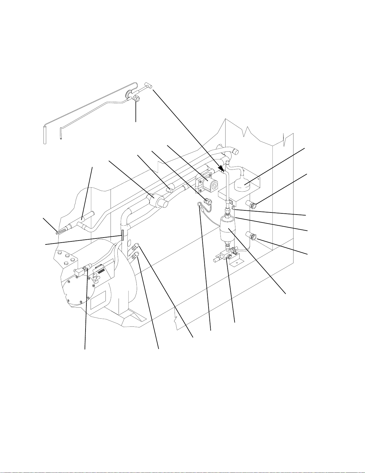
e. Receiver Section
discharge pressure regulator valve.
The receiver section consists of quench expansion
valve, manual liquid line valve, filter-drier, receiver
with sight glass/moisture-liquid indicator, condenser
pressure transducer (CPT), fusible plug, suction
modulation valve, suction solenoid valve, and
6
5
4
3
2
1
18
The supply temperature sensor (STS), supply recorder
sensor (SRS) and ambient sensor (AMBS) are located at
the right side of the compressor.
7
8
9
19
17
1. Discharge Pressure Regulator Valve
2. Suction Modulation Valve (SMV)
3. Schrader Valve
4. Supply Air Thermometer Port -- Optional
5. Suction Solenoid Valve (SSV)
6. Quench Expansion Valve
7. Electro-Coated Modular Receiver
8. Sight Glass
9. Fusible Plug
10. Condenser Pressure Transducer (CPT) --
Figure 2-5. Units with Receiver
10
11
12
13
14
15
16
Located on back side of Receiver)
11. Sight Glass/Moisture Indicator
12. Filter-Drier
13. Manual Liquid Line Valve
14. Ambient Sensor (AMBS)
15. Supply Temperature Sensor (STS)
16. Supply Recorder Sensor (SRS)
17. High Pressure Switch (HPS)
18. Thermistor Sensor (CPDS)
19. Thermistor Sensor (CPSS)
2-6T-268-07
Page 26
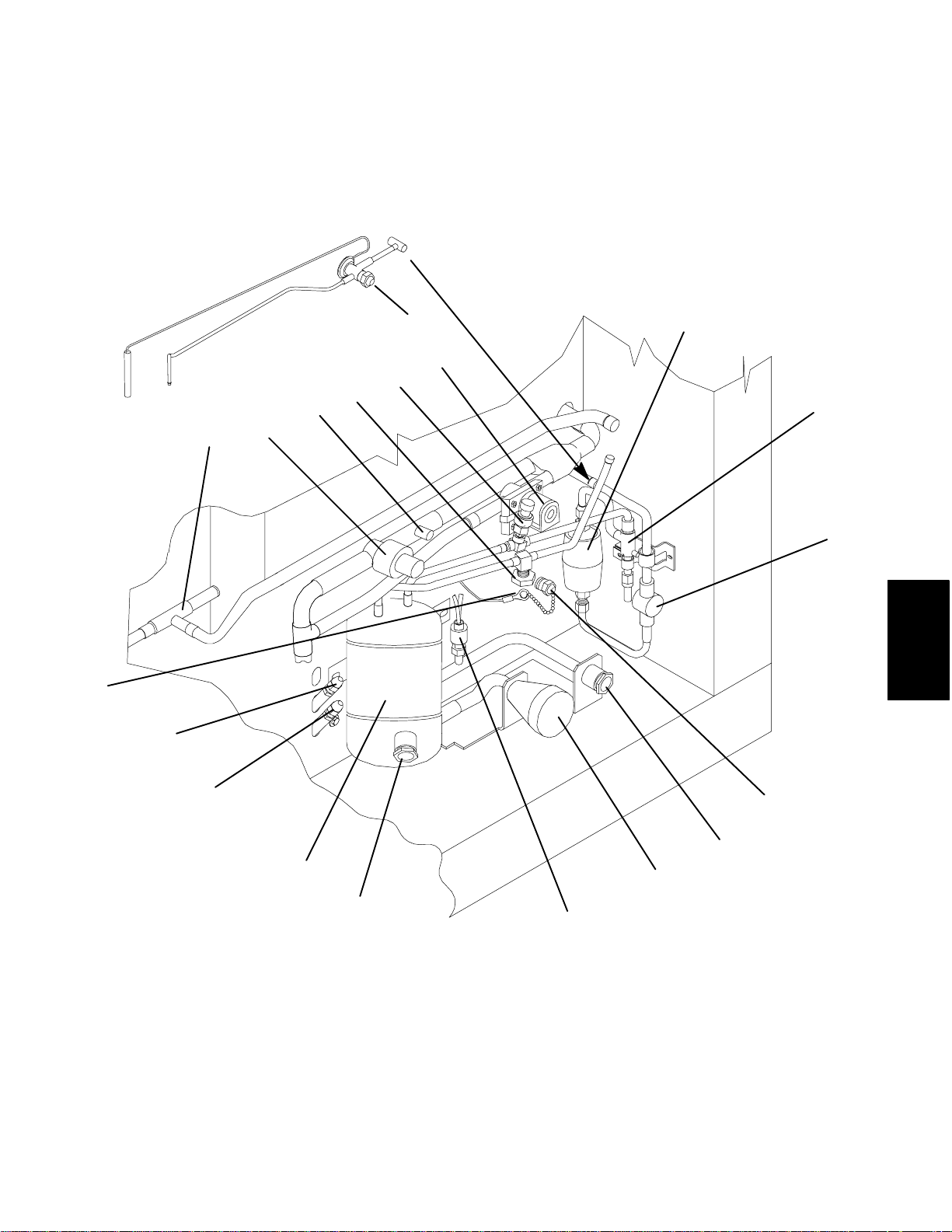
f. Water-Cooled Condenser Section (Optional)
The water-cooled condenser section consists of
water-cooled condenser, sight glass, moisture-liquid
indicator, quench expansion valve, rupture disc,
condenser pressure transducer (CPT), filter-drier,
suction modulation valve, suction solenoid valve,
discharge pressure regulator valve, water hook-up
couplings and water pressure switch.
The supply temperature sensor (STS), supply recorder
sensor (SRS) and ambient sensor (AMBS) are located at
the right side of the compressor.
19
18
7
6
5
4
3
1
2
8
9
10
SECTION 2
17
16
15
1. Discharge Pressure Regulator Valve
2. Suction Modulation Valve (SMV)
3. Schrader Valve
4. Rupture Disc
5. Condenser Pressure Transducer (CPT)
6. Suction Solenoid Valve (SSV)
7. Quench Expansion Valve
8. Filter-Drier
9. Manual Liquid Line Valve
10. Moisture-Liquid Indicator
Figure 2-6. Units with Water-Cooled Condenser
11
12
13
14
11. Supply Air Thermometer Port -- Optional
12. Coupling (Water In)
13. Self Draining Coupling (Water Out)
14. Water Pressure Switch (WPS)
15. Sight Glass
16. Water-Cooled Condenser
17. Supply Recorder Sensor (SRS) -- Optional
18. Supply Temperature Sensor (STS)
19. Ambient Sensor (AMBS)
2-7 T-268-07
Page 27
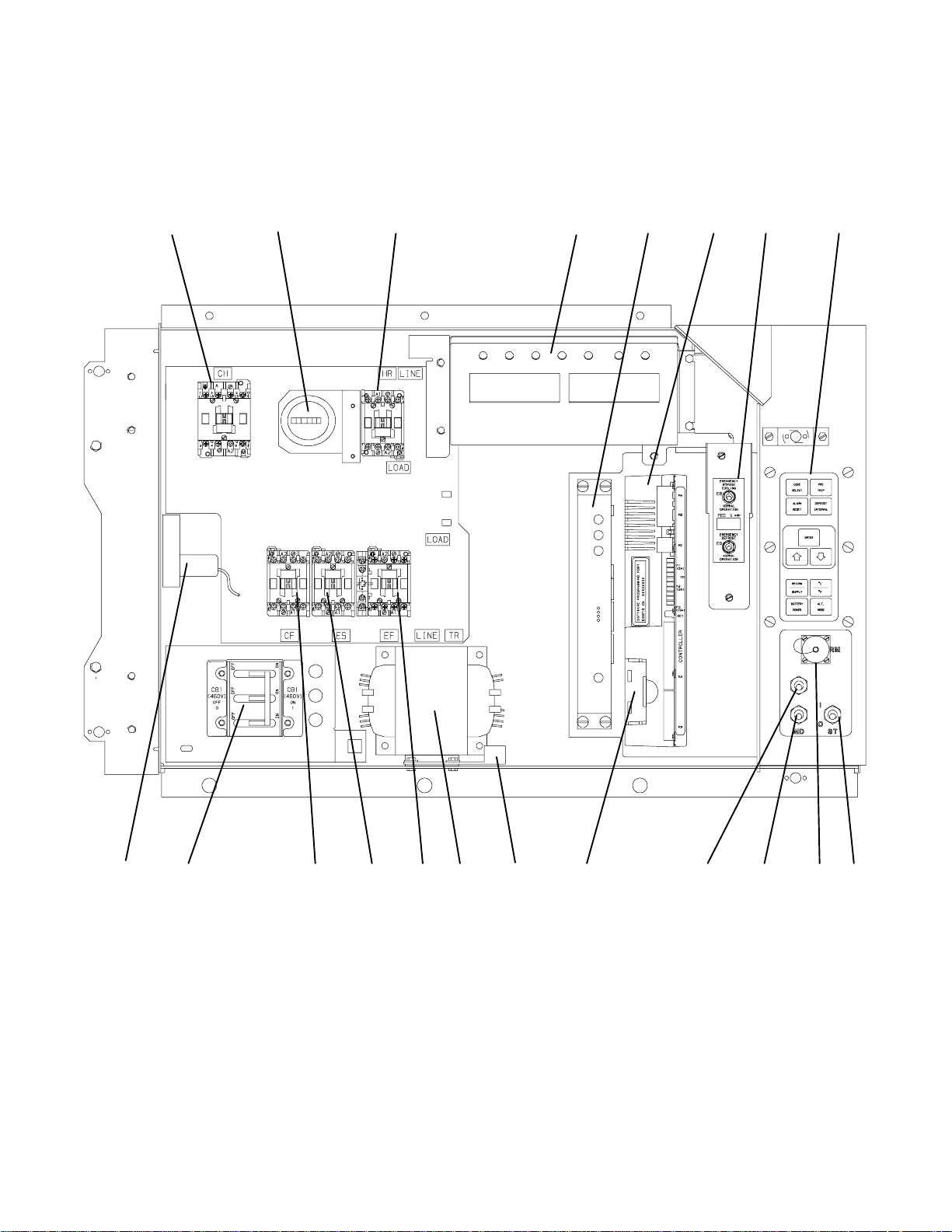
g. Control Box with a Single-Speed Compressor
1
The control box includes the manual switches, circuit
breaker(s), contactors, transformer, fuses, key pad,
display module, current sensor module,
1345610
2
Controller/DataCORDER module (See Figure 2-7), an
optional remote monitoring unit (CI), and an optional
emergency bypass cooling switch (EB), emergency
defrost switch (ED) and emergency defrost fuse (FED).
7
8
9
151718 16
1. Compressor Contactor (CH)
2. Hour Meter (HM) -- Optional
3. Heat Contactor (HR)
4. Display Module
5. Remote Monitoring Unit (RMU) -- Optional
6. Controller/DataCORDER Module
7. Emergency Bypass Cooling Switch (EB)--Optional
8. Emergency Defrost Fuse (FED) -- Optional
9. Emergency Defrost Switch (ED) -- Optional
10. Key Pad
11. Start-Stop Switch (ST)
12. Remote Monitoring Receptacle (RM) -- Optional
Figure 2-7. Control Box on Units with a Single-Speed Compressor
13. Manual Defrost Switch (MDS)
14. Condenser Fan Switch (CFS) -- Optional
15. Controller/DataCORDER Battery Pack -- Optional
16. Interrogator Connector -- Optional location for
some models
17. Control Transformer (TR)
18. Evaporator Fan Contactor (EF) High Speed
19. Evaporator Fan Contactor (ES) Low Speed
20. Condenser Fan Contactor (CF)
21. Circuit Breaker (CB-1) -- 460V
22. Current Sensor Module (CS)
2-8T-268-07
14
13 1219202122
1
Page 28
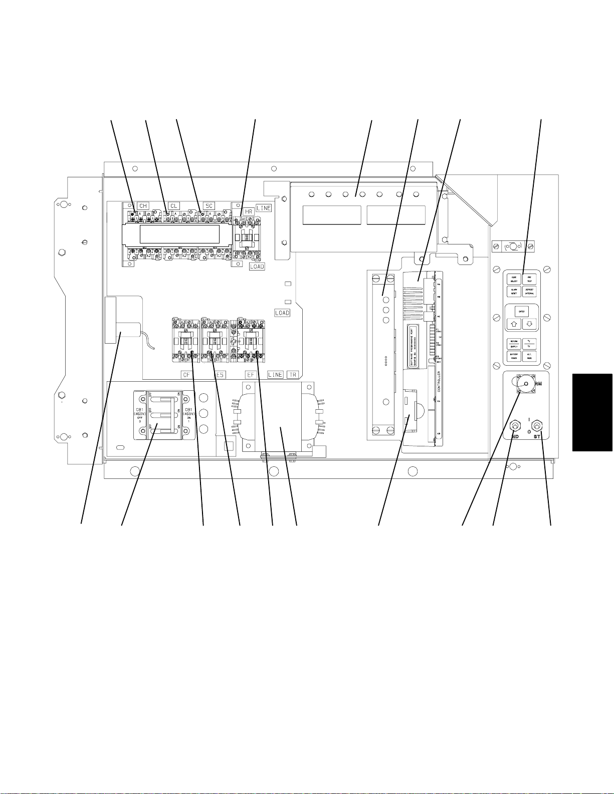
h. Control Box with a Two-Speed Compressor
(Optional)
The control box includes the manual switches, circuit
breaker(s), contactors, transformer, fuses, key pad,
1
23
CAUTION: DO NOT MANUALLY
ENGAGE CONTACTORS
45
display module, current sensor module,
Controller/DataCORDER module (See Figure 2-8),
and an optional remote monitoring unit (CI).
6
78
18
17
16
15
1. Compressor Contactor (CH) High Speed
2. Compressor Contactor (CL) Low Speed
3. Compressor Contactor (SC) Shorting
4. Heat Contactor (HR)
5. Display Module
6. Remote Monitoring Unit (RMU) -- Optional
7. Controller/DataCORDER Module
8. Key Pad
9. Start-Stop Switch (ST)
Figure 2-8. Control Box on Units with a Two-Speed Compressor (Optional)
14
13
12
11
10
10. Manual Defrost Switch (MDS)
11. Remote Monitoring Receptacle (RM) -- Optional
12. Controller/DataCORDER Battery Pack -- Optional
13. Control Transformer (TR)
14. Evaporator Fan Contactor (EF) High Speed
15. Evaporator Fan Contactor (ES) Low Speed
16. Condenser Fan Contactor (CF)
17. Circuit Breaker (CB-1) -- 460V
18. Current Sensor Module (CS)
SECTION 2
9
2-9 T-268-07
Page 29
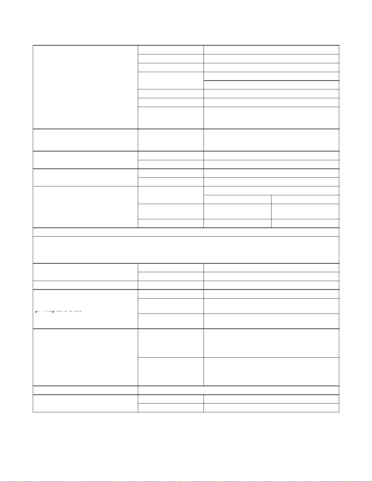
2.2 REFRIGERATION SYST EM DATA
Weight(
Dry)
i.Compressor/MotorAssembl
y
k.H
T
h
l.H
igh
P
h
UnitConf
i
ibleP
l
p.RuptureDisc
q
q.CondenserPressure
s.WaterPressureSwitch
Number of Cylinders 6
Model 06DR
CFM 41
118 kg (260 lb) - Single-Speed
129.39 kg (285.25 lb) - Two-Speed
Approved Oil Castrol Icematic -- SW20
Oil Charge 3.6 liters (7.6 U.S. pints)
The oil level range, with the compressor off,
should be between the bottom and one-eighth
level of the capacity of the sight glass.
4.48 to 6.67 _C(8to12_F)
Charge Requirements -- R-134a
2* row condenser 4* row condenser
4.5kg(9.0lbs) 5.22 kg (11.5 lbs)
j. Expansion Valve Superheat
eaterTermination
ressureSwitc
m. Refrigerant Charge
ermostat
Oil Sight Glass
Verify at --18 _C
(0 _F) container box
temperature
Opens 54 (¦ 3) _C = 130 (¦ 5) _F
Closes 38 (¦ 4) _C = 100 (¦ 7) _F
Cutout 25 (¦ 1.0) kg/cm@ = 350 (¦ 10) psig
Cut-In 18 (¦ 0.7) kg/cm@ = 250 (¦ 10) psig
guration
Water-Cooled
Condenser
Receiver 3.74 kg (8.25 lbs) 4.88 kg (10.75 lbs)
* RefertoTable1-1.
NOTE
When replacing the components (n.), (o.) and (p.) in section 2.2, refer to the installation instructions
included with the ordered new part for additional information.
n.Fus
o. Sight Glass/Moisture Indicator Torque 8.9 to 9.7 mkg (65 to 70 ft-lbs)
p. Rupture Disc
. Condenser Pressure
Transducer (CPT)
r. Unit Weight Refer to unit model number plate, see Figure 2-1 for location of plate.
s. Water Pressure Switch
(Optional)
ug
Melting point 99 _C = (210 _F)
Torque 6.2 to 6.9 mkg (45 to 50 ft-lbs)
Bursts at 35 5% kg/cm@ = (500 5% psig)
Torque
(P/N 14-00215-03)
Torque
(P/N 14-00215-04)
Condenser Fan Starts
Condenser Fan Stops
Cut-In 0.5 ¦ 0.2 kg/cm@ (7 ¦ 3psig)
Cutout 1.6 ¦ 0.4 kg/cm@ (22 ¦ 5psig)
The condenser fan will start if the condenser
pressure is greater than 14.06 kg/cm@ (200
psig) OR the condenser fan is OFF for more
The condenser fan will stop if the condenser
pressure is less than 9.14 kg/cm@ (130 psig)
AND the condenser fan remains ON for at least
1.4to2 mkg(10to15ft-lbs)
6.2 to 6.9 mkg (45 to 50 ft-lbs)
than 60 seconds.
30 seconds.
2-10T-268-07
Page 30
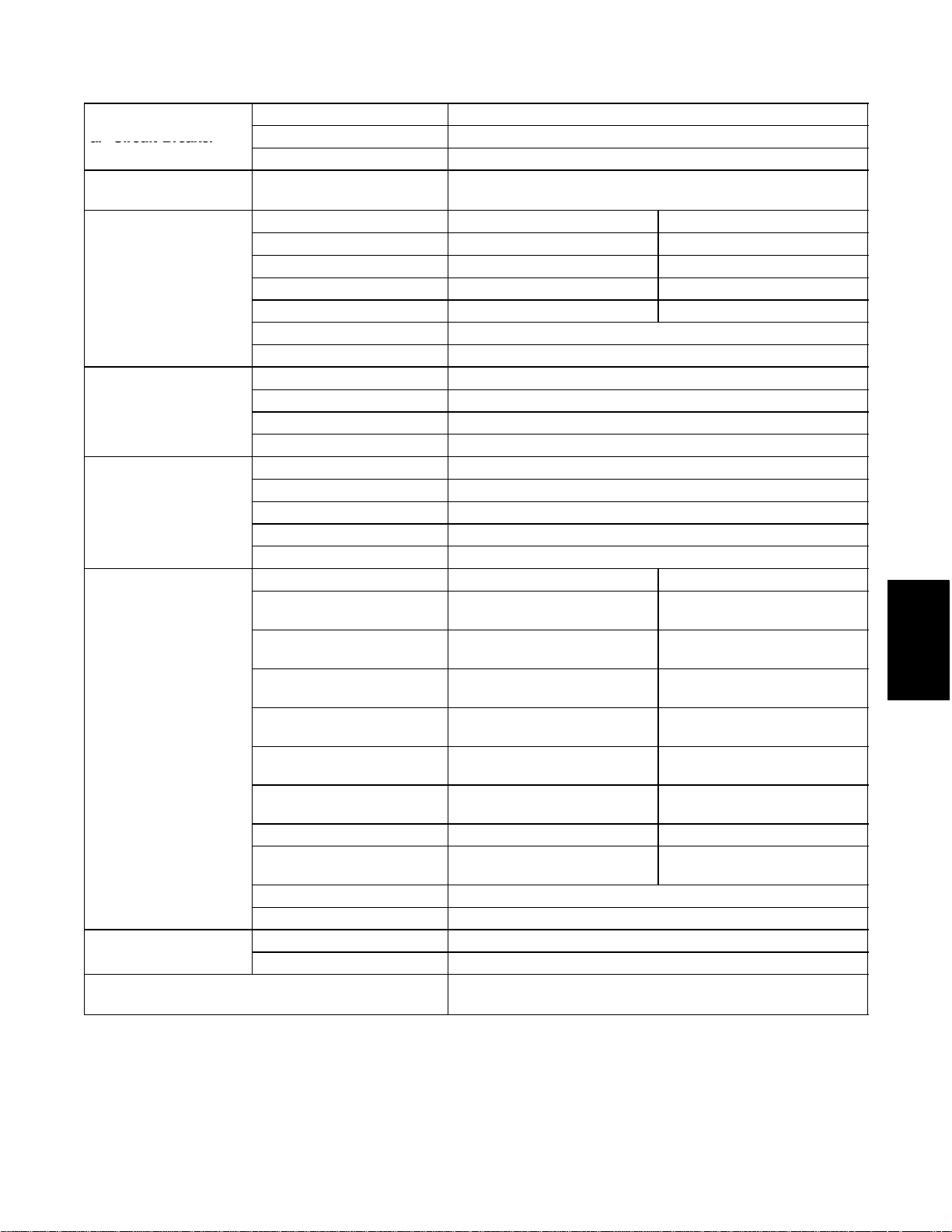
2.3 ELECTRICAL DATA
a.CircuitBreake
r
Mot
d.DrainPanH
Heat
f.EvaporatorFan
CB-1 Trips at 29 amps
a. Circuit Breaker
b. Compressor
Motor
c. Condenser Fan
or
eaters
e. Evaporator Coil
ers
Motor(s)
g.Fuses
h. Compressor Crankcase Heater (CCH) --
Optional
CB-2 (50 amp) Trips at 62.5 amps
CB-2 (70 amp) Trips at 87.5 amps
Full Load Amps (FLA)
Full Load Amps 1.3 amps 1.6 amps
Horsepower 0.43 hp 0.75 hp
Rotations Per Minute 1425 rpm 1725 rpm
Voltage and Frequency 360 -- 460 vac ¦ 1.25 hz 400 -- 500 vac ¦ 1.5 hz
Bearing Lubrication Factory lubricated, additional grease not required.
Rotation Counter-clockwise when viewed from shaft end.
Number of Heaters 1
Rating 750 watts +5 /--10 % @ 460 vac
Resistance (cold) 285 ¦ 7.5% ohms nominal
Type Sheath
Number of Heaters 4
Rating 750 watts +5/--10% each @ 230 vac
Resistance (cold) 66.8 to 77.2 ohms
Ambient @20_C(68_F)
Type Sheath
Full Load Amps -- High
Speed
Full Load Amps -- Low
Speed
Nominal Horsepower -High Speed
Nominal Horsepower -Low Speed
Rotations Per Minute -High Speed
Rotations Per Minute -Low Speed
Voltage and Frequency 360 -- 460 vac ¦ 1.25 hz 400 -- 500 vac ¦ 1.5 hz
Voltage and Frequency --
using modular transformer
Bearing Lubrication Factory lubricated, additional grease not required
Rotation Clockwise when viewed from shaft end.
Control Circuit 15 amps (F3)
Controller/DataCORDER 5amps(F1&F2)
17.6 amps @ 460 vac
(with current limiting set at 21 amps)
380 vac, 3 Phase, 50 hz 460 vac, 3 Phase, 60 hz
380 vac, 3 Phase, 50 hz 460 vac, 3 Phase, 60 hz
1.6 amps 2.0 amps
0.8 amps 1.0 amps
0.70 hp 0.84 hp
0.09 hp 0.11 hp
2850 rpm 3450 rpm
1425 rpm 1750 rpm
180 -- 230 vac ¦ 1.25 hz 200 -- 250 vac ¦ 1.5 hz
180 watts @ 460 vac
SECTION 2
2-11 T-268-07
Page 31

i. HumiditySensor
i.HumiditySenso
r
()p
(HS) -- Optional
Orange wire Power
Red wire Output
Brown wire Ground
Input voltage 5vdc
Output voltage 0to3.3vdc
Output voltage readings verses relative humidity (RH) percentage:
30% 0.99 V
50% 1.65 V
70% 2.31 V
90% 2.97 V
2.4 POWER AUTOTRANSFORMER (Optional)
WARNING
Do not attempt to remove power plug(s)
before turning OFF start-stop switch (ST),
unit circuit breaker(s) and external power
source.
Make sure the power plugs are clean and dry
before connecting to any power receptacle.
a. Step-Up Power Autotransformer
The modular transformer (if equipped) is located under
the condenser coil on the left-hand side of the unit (see
Figure 2-9).
The modular transformer (item 1, Figure 2-9) provides
380/460 vac, 3-phase, 50/60 hertz power to the unit
when the 230 vac (black) power cable is connected to a
190/230 vac, 3-phase power source. The module, in
addition to thetransformer, includesa 230 vac cable and
a receptacle to accept the unit 460 vac power plug. The
modular transformer may be equipped with an optional
circuit breaker (CB-2).
WARNING
2. Plug the 230 vac (black) cable into a de-energized
190/230 vac, 3-phase power source. Energize the
power source. Set circuit breaker (CB-2 if
equipped) to position “1” (ON). C lose and secure
control box door and place the start-stop switch
(ST) in position “1” (ON) to start the unit.
c. To Operate Unit on 380/460 vac Power Supply
1. Make sure start-stop switch (ST, on control panel)
and circuit breaker (CB-1, in the control box) are in
position “0” (OFF).
2. Plug the 460 vac (yellow) cable into a de-energized
380/460 vac, 3-phase power source. Energize the
power source. Place circuit breaker (CB-1) in
position “1” (ON). Close and secure control box
door and then place the start-stop switch (ST) in
position “1” (ON) to start the unit.
3
2
Do not attempt to unplug the power cable
connected to the autotransformer before
performing the following operations: Move
the start-stop switch (ST), the unit circuit
1
breaker(s), CB-1 and CB-2 (if equipped)
and any external power source to their OFF
positions.
b. To Operate Unit on 190/230 vac Power Supply
1. Make sure that the start-stop switch (ST, on control
panel) and circuit breaker (CB-2 if equipped, on the
modular transformer) are in position “0” (OFF).
Make sure the 460 vac power plug is locked into the
1. Dual Voltage Modular Transformer
2. Circuit Breaker (CB-2) 230V (Optional)
3. 460 vac Power Receptacle
receptacle on the modular transformer and circuit
breaker (CB-1, in the control box) is in position “1”
(ON).
2-12T-268-07
Figure 2-9. Power Autotransformer (Optional)
Page 32

2.5 UPPER FRESH AIR MAKEUP VENT
The purpose of t he fresh air makeup vent is to provide
ventilation for commodities that require fresh air
circulation. The vent must be closed when transporting
frozen foods or controlled atmosphere loads.
Air exchange depends on static pressure differential,
which will vary depending on the container and how the
container is loaded. The chart below gives air exchange
values for an empty container. Higher values can be
expected for a fully loaded container.
arrow on the disc with the percentage of desired air flow
marked on the supplied label (see Figure 2-1).
2.6 LOWER FRESH AIR MAKEUP VENT
(Optional)
The purpose of the lower fresh air makeup vent is to
provide ventilation for commodities that require fresh
air circulation. The vent must be closed when
transporting frozen foods.
ZERO EXTERNAL STATIC PRESSURE, 50HZ POWER
AIR
FLOW
(CMH)
225
200
175
150
125
100
75
50
25
0
0 102030405060708090100
PERCENT OPEN
For 60HZ operation multiply air flow values from curve by 1.2
a. Full Open or Closed Positions
T-B AR
2-3/8 ”
Air exchange depends on static pressure differential,
which will vary depending on the container and how the
container is loaded. The chart across gives air exchange
values for an empty container. Higher values can be
expected for a fully loaded container.
a. Full Open or Closed Positions
The air slide is supplied with two adjustable air control
discs. The fresh air makeup can be adjusted for 15, 35,
50 and 75cubic meters perhour (CFM). The airflow has
been established at 60 Hz power, and a 2 1/2 inch T bar,
with 15 mm (0.6 inch) H
O external static above free
2
blow.
Maximum air flow is achieved by loosening the hex
nuts and rotating each disc to the maximum open
position (100% open). The closed position is 0% air
flow.
The operator may also adjustthe openings to increase or
decrease the air flow volume to meet the required air
flow.
NOTE
SECTION 2
Maximum air flow is achieved by loosening the wing
nut and rotating the disc to the maximum open position
(100% open). The closed position is 0% air flow.
Two slots and a stop are designed into the disc for air
flow adjustments. The first slot allows for a 0 t o 30% air
flow, and the second slot allows for a 30 to 100% air
flow. To increase the percentage of air flow, the wing
nut must be loosened, and the disc rotated until the
desired percentage of air flow matches with the arrow on
the disc. Tighten the wing nut. To clear the gap between
the slots, loosen the wing nut until the disc clears the
stop, and rotate the disc for the second slot.
The operator may also increase or decrease the air flow
volume to meet the required air flow by aligning the
The main air slide is in the fully closed position
during reduced air flow operation.
a. Air Sampling for Carbon Dioxide (CO2) Level
Loosen hex nuts and move the cover until the arrow on
the cover is aligned with the “atmosphere sampling
port” label. Tighten the hex nuts and attach a 3/8 hose to
the sampling port.
If the internal atmosphere content has reached an
unacceptable level, the operator may adjust the disc
opening to meet the required air flow volume to
ventilate the container.
2-13 T-268-07
Page 33

2.7 REFRIGERATION CIRCUIT WITH RECEIVER
Starting at the compressor, the suction gas is
compressed to a higher temperature and pressure.
When operating with the air-cooled condenser, the gas
flows through the discharge service valve into the
pressure regulator valve that is normally open. The
pressure regulator valve restricts the flow of refrigerant
to maintain a minimum discharge pressureof 5 kg/cm@
(70 psig). Refrigerant gas thenmoves into the air-cooled
condenser. Air flowing across the coil fins and tubes
cools the gas to saturation temperature. By removing
latent heat, the gas condenses to a high pressure/high
temperature liquid and flows to the receiver which
stores the additional charge necessary for low
temperature operation.
From the receiver, the liquid refrigerant continues
through the manual liquid line valve, t he filter-drier
(which keeps refrigerant clean and dry), and a heat
exchanger that increases subcooling of liquid
refrigerant to the thermostatic expansion valve. As the
liquid refrigerant passes through the orifice of the
expansion valve, some of it vaporizes into a gas (flash
gas). Heat is absorbed from the return air by the balance
of the liquid, causing it to vaporize in the evaporator
coil. The vapor then flows through the suction
modulation valve (and suction solenoid valve under
some conditions) to the compressor.
The thermostatic expansion valve bulb on the suction
line near the evaporator coil outlet controls the
thermostatic expansion valve, maintaining a constant
superheatat the coil outlet regardless of loadconditions,
except at abnormally high container temperatures such
as during pulldown (valve at maximum operating
pressure condition).
NOTE
A pressure control system has been
incorporated by means of a condenser pressure
transducer (CPT) and condenser pressure
control (CPC) logic to maintain discharge
pressures above 130 psig in low ambients.
Regardless of pressure, CPC will be disabled at
every compressor start-up, 15 seconds before
the compressor is energized and 30 seconds
after. An exception, for two-speed compressor
units, is the low speed to high speed switching
sequence, where CPC will be disabled while
SMV is at 0% during the entire switching
sequence for a total of 47 seconds.
a. At ambients below 27_C(80_F), the condenser
fan will cycle on/off depending on condenser
pressure and on/off times.
1. The condenser fan will start if the condenser
pressure is greater than 200 psig OR the condenser
fan is OFF for more than 60 seconds.
2. The condenser fan will stop if the condenser
pressure is less than 130 psig AND the condenser
fan remains ON for at least 30 seconds.
b. At ambients above 27_C(80_F), condenser
pressure control (CPC) is disabled and the
condenser fan runs continuously.
2-14T-268-07
Page 34

6
3
8
5
9
3
2
4
19
7
17
10
11
16
1
1. Suction Service Valve
2. Discharge Service Valve
3. Discharge Pressure Regulator Valve
4. Air-Cooled Condenser
5. Evaporator
6. Thermostatic Expansion Valve
7. External Equalizer Line
8. Thermostatic Expansion Valve Bulb
9. Heat Exchanger
10. Fusible Plug (Located on back of receiver)
Figure 2-10. Refrigeration Circuit with Receiver
18
1415
11. Sightglass
12. Condenser Pressure Transducer (CPT)
(Located on the back-side of the receiver)
13. Sight Glass/Moisture Indicator
14. Electro-Coated Modular Receiver
15. Manual Liquid Line Valve
16. Filter-Drier
17. Quench Expansion Valve
18. Suction Solenoid Valve
19. Suction Modulation Valve
12
1
SECTION 2
2-15 T-268-07
Page 35

2.8 REFRIGERATION CIRCUIT WITH THE
WATER-COOLED CONDENSER (Optional)
Starting at the compressor, the suction gas is
compressed to a higher temperature and pressure.
When operating with the water-cooled condenser, the
gas flows through the discharge service valve into the
pressure regulator valve that is normally open. The
pressure regulator valve may restrict the flow of
refrigerant to maintain a minimum discharge pressure
of 5 kg/cm@ (70 psig).
Refrigerant gas then moves through the air-cooled coil
to the water-cooled condenser. As the refrigerant flows
across the water chilled coiled tube bundle, it is cooled
to saturation temperature and exits the condenser as a
high pressure/saturated liquid.
From the water-cooled condenser, the liquid refrigerant
continues through the manual liquid line valve, the
filter-drier (which keeps refrigerant clean and dry), a
moisture-liquid indicator, and a heat exchanger that
increases subcooling of liquid refrigerant to the
thermostatic expansion valve. As the liquid refrigerant
passes through the orifice of the expansion valve, some
of it vaporizes into a gas (flash gas). Heat is absorbed
from thereturn air by thebalance of t he liquid, causing it
to vaporize in the evaporator coil. The vapor then flows
through the suction modulation valve (and suction
solenoid valve under some conditions) to the
compressor.
The thermostatic expansion valve bulb (on the suction
line near the evaporator coil outlet) controls the
thermostatic expansion valve, maintaining a constant
superheat at the coil outlet regardless of load conditions
except at abnormally high container temperatures such
as during pulldown (valve at maximum operating
pressure condition).
2.9 WATER-COOLED CONDENSER (Optional)
The water-cooledcondenser is used when coolingwater
is available and heating the surrounding air is
objectionable, such as in a ship’s hold.
The water-cooled condenser is of the shell and coil type,
with water circulating through the cupro-nickel coil.
The refrigerant vapor is admitted to the shell side and is
condensed on the outer surface of the coil.
2.9.1 Water--Cooled Condenser with Water
Pressure Switch (WP)
For operation of the refrigeration unit w ith the
water-cooled condenser, do the following:
a. Connect the water supply line to the inlet side of
condenserand the dischargeline to the outlet side of
the condenser.
b. Maintain a flow rate of 11 to 26 liters per minute (3
to 7 gallons per minute). The water pressure switch
will open to de-energize the condenser fan relay.
The condenser fan motor will stop and will remain
stopped until the water pressure switch closes.
The refrigeration unit operating with the water-cooled
condenser will perform as outlined in section 4.4 except
that the condenser fan motor is stopped in all modes.
To shift to air-cooled condenser operation, do the
following:
Disconnect the water supply and the discharge line to
the water-cooled condenser. The refrigeration unit will
shift to air-cooled condenser operation when the water
pressure switch closes. (Refer to section 2.2.)
2.9.2 Water-Cooled Condenser with Condenser
Fan Switch (CFS)
For operation of the refrigeration unit w ith the
water-cooled condenser w ith (CFS), do the following:
a. Connect the water supply line to the inlet side of
condenserand the dischargeline to the outlet side of
the condenser.
b. Maintain a flow rate of 11 to 26 lpm (3 to 7 gpm).
c. Set CFS switch to position ”O” when water is
supplied to the water-cooled condenser. This will
de-energize the condenser fan relay. The condenser
fan motor will stop and will remain stopped until
the CFS switch is set to position ”1.”
The refrigeration unit operating with the water-cooled
condenser and the CFS switch in position ”O,” will
perform as outlined in section 4.4 except that the
condenser fan motor is stopped in all modes.
WARNING
When water flow is below 11 lpm (3 gpm) or
when water-cooled operation is not in use,
the CFS switch MUST be set to position ”1”
or the unit will not operate properly.
To shift to air-cooled condenser operation, do the
following:
Turn the unit OFF and set the C FS switch to position
”1.” Disconnect the water supply and the discharge line
to the water-cooled condenser. The unit should now
perform as outlined in section 4.4.
2-16T-268-07
Page 36

6
8
5
9
3
2
4
18
16
7
10
11
12
13
1. Suction Service Valve
2. Discharge Service Valve
3. Discharge Pressure Regulator Valve
4. Air-Cooled Condenser
5. Evaporator
6. Thermostatic Expansion Valve
7. External Equalizer Line
8. Thermostatic Expansion Valve Bulb
9. Heat Exchanger
10. Rupture Disc
Figure 2-11. Refrigeration Circuit with Water-Cooled Condenser (Optional)
17
19
15
14
SECTION 2
1
11. Manual Liquid Line Valve
12. Moisture-Liquid Indicator
13. Condenser Pressure Transducer (CPT)
14. Filter-Drier
15. Sight Glass
16. Water-Cooled Condenser
17. Suction Solenoid Valve
18. Suction Modulation Valve
19. Quench Expansion Valve
2-17 T-268-07
Page 37

2.10 SUCTION SOLENOID VALVE
The suction solenoid valve, shown in Figure 2-5, is
controlled by the Controller relay (TS).
a. Operation
If set point is below --10_C(+14_F), or --5_C(+23_F)
optionally, and the suction solenoid valve override is not
activated, Controller relay (TS) closes to energize the
suction solenoid valve (SSV). Once opened, the
refrigerant flow rate and unit cooling capacity is
increased.
If set point is above --10_C(+14_F), or --5_C(+23_F)
optionally, the suction solenoid valve opens during the
temperaturepulldown period unless the current limiting
suction solenoid overrides or compressor reliability
enhancement logic restricts its use. A pulldown period
begins when the control temperature is more than 5_C
(+9_F) above set point, and ends as soon as the control
temperature equals set point.
For both conditions above, at the instant when the SSV
opens, the SMV will drop to 20% open, then gradually
increase to 100% open. Unless the current limiting
suction solenoid overrides or compressor reliability
enhancement logic (CREL) restricts its use.
b. Suction Solenoid Override
The suction solenoid override function restricts the
opening of the suction solenoid valve (SSV) under
certain high ambient and/or box temperatureconditions
to prevent compressor overload under these high
capacity conditions. If the primary return sensor (RTS)
fails (alarm codeAL56), the suction solenoid valve will
not open unless the ambient temperature is less than
10_C(50_F). If the ambient sensor fails (AL57), the
suction solenoid valve will not be allowed to open until
the return air temperature is less than 1.67_C(35_F). If
both the ambient and return air (RTS) sensors fail, the
suction solenoid valve will not be allowed to open until
at least one of the sensors is repaired.
2.11 REMOTE MONITORING (Optional)
NOTE
The in-range light will be illuminated if the
container control air temperature is within the
tolerance selected. Refer to section 3.1.4
(Code 30).
When the remote monitor plug is connected to the
remote monitoring receptacle, the following remote
circuits are energized:
CIRCUIT FUNCTION
Sockets B to A Energizes remote cool light
Sockets C to A Energizes remote defrost light
Sockets D to A Energizes remote in-range light
2-18T-268-07
Page 38

2.12 SAFETY AND PROTECTIVE DEVICES
IP-CP or HP S will shut down the compressor.
Unit components are protected from damage by safety
and protective devices listed in Table 2-1.These
devices monitor the unit operating conditions and open
a set of electrical contacts when an unsafe condition
occurs.
Open safety switch contacts on either or both of devices
Table 2-1. Safety and Protective Devices
UNSAFE CONDITION SAFETY DEVICE DEVICE SETTING
Circuit Breaker (CB-1) -- Manual Reset Trips at 29 amps (460 vac)
Excessive current draw
Excessive current draw on the
control circuit
Excessive current draw by the
Controller/DataCORDER
Excessive condenser fan
motor winding temperature
Circuit Breaker (CB-2, 50 amp) --Manual
Reset
Circuit Breaker (CB-2, 70 amp) --Manual
Reset
Fuse (F3) 15 amp rating
Fuse (F1 & F2) 5 amp rating
Internal Protector (IP-CM) -- Automatic
Reset
Open safety switch contacts on device IP-CM will shut
down the condenser fan motor.
The entire refrigeration unit will shut down if one of the
following safety devices open: (a) Circuit Breaker(s);
(b) Fuse (F3/15A); or (c) Evaporator Fan Motor Internal
Protector(s) -- (IP-EM).
Trips at 62.5 amps (230 vac)
Trips at 87.5 amps (230 vac)
N/A
Excessive compressor motor
winding temperature
Excessive evaporator fan
motor(s) winding temperature
Abnormal
pressures/temperatures in the
high refrigerant side
Abnormally high discharge
pressure
Internal Protector (IP-CP) -- Automatic
Reset
Internal Protector(s) (IP-EM) -- Automatic
Reset
FusiblePlug--UsedontheReceiver
Rupture Disc -- Used on the Water-Cooled
Condenser
High Pressure Switch (HPS) Opens at 25 kg/cm@ (350 psig)
35 kg/cm@ = (500 psig)
N/A
N/A
93 _C = (200 _F)
SECTION 2
2-19 T-268-07
Page 39

MICROPROCESSOR
3.1 MICRO-LINK 2i CONTROLLER MODULE
SECTION 3
122
1. Micro-Link 2i Controller/DataCORDER Module
2. Connectors
3. Test Points
4. Fuses
Figure 3-1. Micro-Link 2i Controller/DataCORDER Module
342 225
78
6
5. Control Circuit Power Connection
(Location: In back of connector)
6. Battery Pack (Optional)
7. Software Programming Port
8. Mounting Screw
3.1.1 Brief Description
NOTE
Some units are equipped with an optional
emergency bypass switch (EB), which permits
manually overriding a malfunctioning
Controller by locking the unit into a continuous
full cooling mode (see Figure 2-7).
WARNING
Do not attempt to service the
Controller/DataCORDER module.
Breaking the warranty seal will void the
warranty.
CAUTION
Remove the Controller/DataCORDER
module and unplug all wire h arness
connectors before performing any arc
welding on any part of the container.
Do not remove wire harnesses from module
unless you are grounded to the unit frame
with a static safe wrist strap.
The Carrier Transicold Micro-Link 2i
Controller/DataCORDER is a custom-designed
microprocessor-based module which incorporates
embedded software to:
a. Control supply or return air temperature to
extremely tight limits by providing modulated
refrigeration control, electric heat control and
defrost to ensure continuous conditioned air
delivery to the load.
b. Provide dual independent readouts of set point and
supply or return air temperatures.
c. Provide digital readout and ability to select data.
Refer to Table 3-3 for Controller Function Codes.
For Controller alarm digital display identification
refer to Table 3-4.
d. Provide a pre-trip step-by-step checkout of
refrigeration unit performance including: proper
component operation, electronic and refrigeration
control operation, heater operation, probe
calibration and current limiting. Refer to section
3.2.
e. Provide the ability to select or change Codes 27 to
37 and set point without AC power being hooked
up.Refertosection3.1.4.
SECTION 3
3-1 T-268-07
Page 40

f. Provide reprogrammability and configuration
through a memory card. The memory card
automatically downloads new software to the
Controller when inserted, and controls output to the
display for status information.
g. Provide electronic data storage.
NOTE
For the benefit of the reader the remaining parts
of section 3.1 will devote themselves to the
temperature controller portion of the module.
For the integrated DataCORDER refer to
section 3.3.
3.1.2 Controller Programming (Memory) Cards
The programming cards are used for loading software
into the Controller. This is the same concept as using a
floppy diskette to load software into a personal
computer.
The software that can be loaded into the Controller
module comes in one of two forms: “Operational
Software” or “Configuration Software.”
Procedure for loading software:
Refer to section 6.27.1.
Operational Software:
This software operates the Controller module, which
turns fans on and off, turns the compressor on and off,
etc.
Configuration Software:
This software tells the Operational Software what
physical components are built into the container unit.
Refer to Table 3-1.
Programming cardswith either OperationalSoftware or
Configuration Software are available t hrough CTD
Replacement Components Group.
The use of a configuration program card in the field
should only occur under unusual circumstances. Some
of these circumstances may include:
a. A Controller module that has an older version of
Operational Software, when the need exists to
upgrade to a newer version of the software.
b. A physical component in the container unit is
changed to a different component, resulting in a
new configuration for the unit.
c. A Controller module was damaged in such a way
that the integrity or existence of software within the
module is questionable.
3-2T-268-07
Page 41

Table 3-1. Controller Configuration Variables
CONFIGURATION
NUMBER
1 Bypass Valve Enable In Out
2 Evaporator Fan Speed dS (Dual) SS (Single)
3 Number of Sensor Probes FoUR dUAL
4 Dehumidification Mode On Off
5 Probe Calibration noCal CAL
6 Condenser Fan Speed Select Off (Single) On (Variable)
7 Unit Selection, 20FT/ 40FT/45FT 40ft 20ft,45
8 Single Phase/Three Phase Motor 1Ph 3Ph
9 Refrigerant Selection r134a r12, r22, bLEnd
10 Compressor Speed Out (Single) In (Dual)
11 Defrost “Off” Selection noOFF OFF
12 TXV/Solenoid Quench Valve Out (TXV) In (Solenoid)
13 Unloader Out In
14 Condenser Pressure Control (CPC) In Out
15 Discharge Temperature Sensor Out In
16 DataCORDER Option On (Yes) Off (No)
17 Discharge Pressure Sensor Out (No) In (Yes)
18 Heater Old (Low Watt) nEW (High Watt)
19 Controlled Atmosphere Out (No) In (Yes)
20 Pressure Sensor (Suction) Out (No) In (Yes)
21 Auto-Transformer Std -22 Economy Mode Option Off Std, Full
23 Defrost Interval Timer Save Option noSAV SAV
24 Advanced Pre-Trip Enhanced Test Off On
25 Pre-Trip Test Points/Results Recording rSLts data
26 Heat Lockout Set to --10_C Set to--5_C
27 Suction Temperature Display Out In
28 Bulb Mode Nor bulb
29 Arctic Mode Out In
30 Compressor Size 41 CFM 37 CFM
31 Probe Check Logic Std SPEC
32 Single Evaporator Fan Option 2EF0 1EF0
33 Snap Freeze Option Off SnAP
34 Degree Celsius Lockout Option bOth _F
35 Humidification Mode Off On
36 Modulation Valve Type 1 2, 3
37 Electronic Partlow rEtur SuPPL, bOth
38 Quench Bypass Valve Out In
39 Current Limit Range Out In
40 Demand Defrost Out In
TITLE DEFAULT OPTION
SECTION 3
3-3 T-268-07
Page 42

3.1.3 General Layout of the Controller Section
The Micro-Link 2i Controller/DataCORDER consists
of a key pad, display module and C ontroller module.
Connectors are used to attach the wiring of the unit t o
the Controller module. The Controller module is
designed to permit ease of installation and removal.
All control functions are accessed by key pad selections
and viewed on the display module which are designed
for optimum user friendliness and convenience.
The key pad (see Figure 3-1) is mounted on the
right-hand side of the control box. The key pad consists
of eleven push-energized membrane switches that act as
the user’s interface with the Controller and the optional
DataCORDER. Refer to Table 3-2.
CODE
SELECT
ALARM
LIST
ENTER
RETURN
SUPPLY
BATTERY
POWER
Figure 3-1. Key Pad
PRE
TRIP
DEFROST
INTERVAL
_C
_F
ALT.
MODE
Table 3-2. Key Pad Function
KEY FUNCTION
Change set point upward. Change
codes upward. Scan alarm list upward.
Change user selectable features
Arrow Up
Arrow Down
Return/Sup
ply
_C/_F
Alarm List
Code Select
Defrost
Interval
Pre–Trip
Battery
Power
Enter
ALT. Mode
upward. Pre-trip advance forward.
Pre-trip test interruption. DataCORDER
Function and Alarm Codes are scrolled
upward after the ALT. MODE key is
depressed.
Change set point downward. Change
codes downward. Scan alarm list
downward. Change user selectable
features downward. Pre-trip repeat
backward. DataCORDER Function and
Alarm Codes are scrolled downward
after the ALT. MODE key is depressed.
Displays non-controlling probe
temperature (momentary display).
Displays alternate temperature scale
(momentary display).
Displays alarm list and clearing of the
alarm queue (when followed by Enter
key) for the Controller, and also for the
DataCORDER after the ALT. MODE
key is depressed.
Access function codes (see arrow up
and arrow down) for the Controller,
and also for the DataCORDER after
the ALT. MODE key is depressed.
Displays selected defrost interval.
Displays a pre-trip selection menu.
Discontinues pre-trip in progress.
If the unit is equipped with the optional
battery pack, initiate the battery
backup mode to allow set point and
function code selection if no mains
power is present.
Entering a set point change.
Extending to 30 seconds the time a
chosen data function code is
displayed. Entering the value of a user
selectable mode. Clearing the alarm
list and initiating pre-trip. Also used for
various DataCORDER functions after
the ALT. MODE key is depressed.
Allows access to DataCORDER
function codes, alarm codes,
DataCORDER configuration and
scrollback.
3-4T-268-07
Page 43

The display module (see F igure 3-2) is mounted at a 20
degree downward tilt to aid in visibility. The display
module consists of:
a. Two 25mm (1 inch) high, five digit LC D displays
which are easily viewed in direct sunlight and
backlighted for superior low-light visibility.
b. Seven Indicators:
S Cool -- White Lamp: Energized when the
refrigerant compressor is energized.
S Heat -- Orange LED: Energized when the
heaters are on, and the unit is in the heat or
defrost mode.
S Defrost -- Orange LED: Energized when the
heaters are on, and the unit is in the defrost
mode.
S In-Range -- Green LED: Energized when the
controlling temperature probe is in range.
(Supply air probe will be used for control in
the perishable ranges and the return a ir probe is
used for control in the frozen ranges.)
S Alarm -- Red LED: Energized when there is
an active or an inactive shutdown alarm
(AL20 to AL27) in the alarm queue.
S Supply -- Yellow LED: Energized when
supply temperature and set point are
displayed. Flashes if dehumidification or
humidification i s enabled on units so
equipped.
S Return -- Yellow LED: Energized when return
temperature and set point are displayed.
COOL HEAT DEFROST IN RANGE ALARM SUPPLY RETURN
SETPOINT/Code AIR TEMPERATURE/Data
Figure 3-2. Display Module
NOTE
The default display m ode will show the set
point temperature (on the left display) and
controlling probe temperature (on the right
display). The controlling probe in the
perishable range will be the SUP PLY air probe
and the controlling probe in the frozen range
will be the RETURN air probe.
3-5 T-268-07
SECTION 3
Page 44

3.1.4 Controller Function Codes
There are thirty-nine functions which the operator may
access to examine the operating status of the unit. To
access these functions, perform the following steps:
Press the CODE SELECT key, then press an arrow key
until the left window displays the desired code number
Table 3-3. Controller Function Code Assignments
(see Table 3-3). For t he display only function codes, the
right window will display t he value of this item for five
seconds before returning to the normal display mode. If
a longer time is desired, pressing the ENTER key will
extend the time to 30 seconds after the last pressing of
the ENTER key. Function codes are explained in
Table 3-3.
CODE
#
Cd01
Cd02
Cd03
Cd04
Cd05
Cd06
Cd07 Main Power Voltage The main supply voltage is displayed.
Cd08
Cd09
Cd10
Cd11
Cd12
Modulation Valve
Opening (%)
Quench Valve
(Open--Closed)
Suction Solenoid
Val v e
(Open--Closed)
Line Current, Phase
A
Line Current, Phase
B
Line Current, Phase
C
Mains Power
Frequency
Ambient
Temperature
Compressor Suction
Temperature
(Optional)
Compressor
Discharge
Temperature
(Optional)
Compressor Suction
Pressure (Optional)
TITLE DESCRIPTION
Inapplicable Functions Display -- ------ --
Display Only Functions
The suction modulation valve (SMV) is a normally open valve which restricts flow
of refrigerant to the compressor when energized by a pulse width modulated
(PWM) output. The amount of valve closure is proportional to the applied current
over the range of 0.2 to 1.3 A. The valve is completely open (right display reads
100%) below 0.2 amps and is completely closed (right display reads 0%) at 1.3
amps.
Shows state of the solenoid quench valve, if so equipped (open or closed).
The suction solenoid valve (SSV) provides maximum refrigerant flow to the
refrigeration unit. This valve will always be open for set points at or below --10_C
(+14_F), or --5_C(+23_F) optionally, and during temperature pulldown periods
unless suction solenoid override or current limiting restricts its use.
Unit current is monitored by two current sensors. The current measured is used
for control and diagnostic purposes.For control processing, the highest of the
Phase A and B current values is used for current limiting purposes. The third
unmeasured leg is calculated based on a current algorithm. For diagnostic
processing, the current draws are used to determine control unit operations.
Whenever a heater or a motor is turned ON or OFF, the current draw
increase/reduction for that activity is measured. The current draw is then tested to
determine if it falls within the expected range of values for the unit. Failure of this
test will result in a pre-trip failure or a control alarm indication.
The value of the main power frequency is displayed in Hertz. The frequency
displayed will be halved if either fuse F1 or F2 is bad and alarm code AL21 is
active.
The ambient sensor (AMBS) measures the temperature outside the container.
For location of the sensor, see Figure 2-5.
Compressor suction temperature is measured just prior to the compressor suction
service valve, and is a display-only temperature.
The compressor discharge temperature is measured near the compressor
discharge valve and is display only.
Compressor suction pressure is displayed using a pressure transducer. Pressure
is displayed in units of psig when code 28 is set to _F and units of bars when
code 28 is set to _C. “P” appears after the value to indicate psig, “b” appears after
the value to indicate bars and “i” appears after the value for inches of mercury.
3-6T-268-07
Page 45

CODE
#
Inapplicable Functions Display -- ------ --
Condenser pressure is displayed using a pressure transducer. Pressure is
Cd13
Cd14
Cd15
Cd16
Cd17
Cd18 Software Revision # The software revision number is displayed.
Cd19 Battery Check
Cd20 Config/Model #
Cd21 Future Expansion This code is for future expansion, and is not in use at this time.
Cd22
Cd23
Cd24
Cd25
Cd26
Condenser Pressure
(CPC)
Compressor
Discharge Pressure
(Optional)
Unloader Valve
(On--Off)
Compressor Motor
Hour Meter
Relative Humidity
(%) (Optional)
Compressor Speed
(High--Low--Off)
Evaporator Fan
Speed
(High--Low--Off)
Controlled
Atmosphere State
(On--Off) (Optional)
Compressor Run
Time Remaining
Until Defrost
Defrost Termination
Sensor Temperature
displayed in units of psig when code 28 is set to _F and units of bars when
function code Cd28 is set to _C. “P” is displayed after the value to indicate psig,
“b” appears after the value to indicate bars and “i” appears after the value for
inches of mercury.
Compressor discharge pressure is displayed using a pressure transducer.
Pressure is displayed in units of psig when function code Cd28 is set to _F and
units of bars when Cd28 is set to _C. “P” is displayed after the value to indicate
psig, “b” appears after the value to indicate bars and “i” appears after the value
for inches of mercury.
The status of the unloader valve (if present) is displayed (on or off).
Records total hours of compressor run time. Total hours are recorded in
increments of 10 hours (i.e., 3000 hours displayed as 300).
This code is only applicable to units with a humidity sensor (HS). This code
displays, as a percent value, the relative humidity at that time.
This code checks the Controller/DataCORDER battery pack. While the test is
running, “btest” will flash on the right display, followed by the result. “PASS” will
be displayed for battery voltages greater than 7.0 volts and for alkaline batteries
with voltages greater than 7.5 volts, “FAIL” will be displayed for battery voltages
between 4.5 and 7.0 volts, and “-- -- --” will be displayed for battery voltages less
than 4.5 volts. After the result is displayed for four seconds, “btest” will again be
displayed, and the user may continue to scroll through the various codes.
This code indicates the dash number of the model for which the Controller is
configured (i.e., if the unit is a 69NT40-511-105, the display will show 11105).
The status of the compressor is displayed (high, low or off).
Displays the current evaporator fan state (high, low or off).
This code shows the state of Controlled Atmosphere (enabled or disabled), if
equipped.
This code displays the time remaining until the unit goes into defrost (in tenths of
an hour). This value is based on the actual accumulated compressor running
time.
The defrost termination sensor (DTS) is located immediately above the
evaporator coil. It is used by the Controller for defrost initiation and termination.
(See Figure 2-2.)
DESCRIPTIONTITLE
SECTION 3
3-7 T-268-07
Page 46

CODE
#
Inapplicable Functions Display -- ------ --
Display Only Functions
DESCRIPTIONTITLE
NOTE
Function codes Cd27 through Cd37 are user-selectable functions. The operator can change the value of
these functions to meet the operational needs of the container.
The defrost interval is the time interval between defrost cycles. Five selectable
values are available: 3, 6, 9, 12 or 24 hours. The factory default value is 12 hours.
The time interval of the first defrost will not begin counting down until defrost
termination sensor (DTS) is below 10_C(50_F). The time interval to the next
defrost cycle is entered into the Controller at the time DTS is below 10_C(50_F)
or at power-up. (See code Cd37 for deviations.) If DTS reaches 25.6_C(78_F) at
any time during the timer count down, the interval is reset and the countdown
begins over. If DTS has failed (i.e., alarm code AL60 is active) and the primary
return sensor temperature is less than 10_C, the interval timer countdown begins.
The interval timer is reset if the return sensor temperature rises above 25.6_C.
(See section 4.4.6.)
Defrost Interval Timer Value Option: If the software is configured to “ON” for this
option, then the value of the defrost interval timer will be saved at power down
and restored at power up. This option prevents short power interruptions from
resetting an almost expired defrost interval, and possibly delaying a needed
defrost cycle.
Cd27
Defrost Interval
(Hours)
NOTE
Cd28
Cd29
Cd30 In-Range Tolerance
Cd31
Temperature Units
(_Cor_F)
Failure Action
(Mode)
Stagger Start Offset
Time (Seconds)
The defrost interval timer counts only during compressor run time.
This code determines the temperature units (_Cor_F) which will be used for all
temperature displays. The user selects _Cor_F by selecting function code Cd28
and pushing the ENTER key. The factory default value is Celsius units.
NOTE
This function code will display “ --- --- --- --- --- “ i f the Controller configuration
variable option 34 is set to _F (refer to Table 3-1).
If all of the control sensors are out of range (alarm code AL26) or there is an
alarm code AL27 failure, the unit will enter the shutdown state defined by the
failure action. The user selects one of four possible actions as designated by a
selection code:
A -- Full Cooling (SMV 100%)
B -- Partial Cooling (SMV 50% open)
C -- Evaporator Fan Only
D -- Full System Shutdown -- Factory Default
The in-range tolerance will determine the band of temperatures around the set
point which will be designated as in-range. If the control temperature is in-range,
the in-range light will be illuminated. There are four possible values:
1. ¦ 0.5_C(¦ 0.9_F)
2. ¦ 1.0_C(¦ 1.8_F)
3. ¦ 1.5_C(¦ 2.7_F)
4. ¦ 2.0_C(¦ 3.6_F) -- Factory Default
The stagger start offset time is the amount of time that the unit will delay at
start-up, thus allowing multiple units to stagger their control initiation when all
units are powered up together. The eight possible offset values are:
0 (Factory Default), 3, 6, 9, 12, 15, 18 or 21 seconds
3-8T-268-07
Page 47

CODE
#
Cd32
Cd33
Cd34
Cd35
Cd36
Cd37
Current Limit
(Amperes)
Dehumidification
Control (% RH)
(Optional)
Economy Mode
(On--Off) (Optional)
Bulb Mode
(Normal--Bulb)
(Optional)
Evaporator Speed
Select
(Cd35 must be in
“Bulb”)
Defrost Temperature
Sensor Setting
(Optional)
DESCRIPTIONTITLE
Inapplicable Functions Display -- ------ --
The current limit is the maximum current demand allowed on any phase at any
time. Limiting the unit’s current (amperage) reduces the load on the main power
and lowers the compressor discharge pressure. When desirable, the limit can be
lowered. Note, however, that capacity is also reduced. The five values for 460vac
operation are:
15, 17, 19, 21 (Factory Default), 23
This code is only applicable to units with a humidity sensor (HS).Relative humidity
set point is available only on units configured for dehumidification. When the
mode is activated, the control probe LED flashes on and off every second to alert
the user. If not configured, the mode is permanently deactivated and Cd33 will
display “-- --------.” When set point is available, it can be set to “OFF.” “TEST,” or 65
to 95% relative humidity in increments of 1%. If bulb mode is active (code Cd35)
and “Lo” speed evaporator motors are selected (code Cd36) then set point
ranges from 60 to 95%. When “TEST” is selected or test set point is entered, the
heaters should be turned on, indicating that dehumidification mode is activated.
After a period of five minutes has elapsed in this mode, the previously selected
mode is reinstated.
Economy mode is a user selectable mode of operation provided for power saving
purposes. Refer to sections 3.1.7.1 and 3.1.7.2 for a more detailed description of
economy mode.
Bulb mode is a user selectable mode of operation that is an extension of normal
dehumidification. If dehumidification is set to “Off,” code Cd35 will display “Nor”
and the user will be unable to change it. After a dehumidification set point has
been selected and entered for code Cd33, the user may then change code Cd35
to “bulb.” After bulb has been selected and entered, the user may then utilize
function codes Cd36 and Cd37 to make the desired changes.
This code is enabled only if a dehumidification set point has been selected using
function code Cd33 and “bulb” has been selected using function code Cd35. If
these conditions are not met, “alt” will be displayed indicating that the evaporator
fans will alternate their speed whenever a dehumidification set point is selected.
This display cannot be changed by the user. If a dehumidification set point has
been selected along with bulb mode then “alt” may be selected for alternating
speed, “Lo” for low speed evaporator fan only, or “Hi” for high speed evaporator
fan only. If a setting other than “alt” has been selected and bulb mode is
deactivated in any manner, then selection reverts back to “alt.”
This code, as with function code Cd36, is used in conjunction with bulb mode and
dehumidification. If bulb mode is active, this code allows the user to change the
temperature above which the defrost termination sensor (DTS) temperature must
go to terminate defrost. It allows the user to change the setting from 4_Cto
25.6_Cin0.1_C(0.2_F) increments. This value is changed using the UP/DOWN
ARROW keys, followed by the ENTER key when the desired value is displayed. If
bulb mode is deactivated in any manner, the DTS setting above which defrost
terminates defaults to the normal 25.6_C(78_F) setting.
NOTE
SECTION 3
In the unlikely event that AL55 activates, Function Codes Cd38 and Cd39 will display SRS and R RS,
respectively.
This code is only applicable to units without a DataCORDER that are configured
to have four probes. If this is true, it will then display the current secondary supply
air temperature.If the unit is configured with a DataCORDER, the Controller
function code Cd38 will display “-- --------.” and the display values for SRS will
appear on the DataCORDER function code dC1.
3-9 T-268-07
Cd38
Secondary Supply
Air Temperature
(Optional)
Page 48

CODE
#
Cd39
Secondary Return
Air Temperature
(Optional)
DESCRIPTIONTITLE
Inapplicable Functions Display -- ------ --
This code is only applicable to units without a DataCORDER, that are configured
to have four probes. If this is true, it will then display the current secondary return
air temperature.If the unit is configured with a DataCORDER, the Controller
function code Cd39 will display “-- --------,” and the display values for RRS will
appear on the DataCORDER function code dC2.
3.1.5 Controller Alarms
The alarm philosophy balances the protection of the
refrigeration unit and that of the refrigerated cargo. The
action taken when an error is detected always considers
the survival of the cargo. Rechecks are made to confirm
that an error actually exists.
Some alarms requiringcompressor shutdown have time
delays before and after to try to keep the compressor on
line. An example is a low mains voltage, when the
voltage drops over 25%, an indication is given on the
display, but the unit will continue to run.
An alarm (See Table 3-4) is indicated by flashing an
alarm codeon the display panel, and forsome alarms, by
the alarm light illuminating.
When an Alarm Occurs:
S The red alarm light will illuminate for “20
series” alarms only.
S If a detectable problem is found to exist, its
alarm code will be alternately displayed with
the set point on the left display.
S The user should scroll through the alarm list
to determine what alarms exist or have
existed. Alarms must be diagnosed and
corrected before the Alarm List can be
cleared.
To Display Alarm Codes:
While in Set Point Selection or Default Display mode,
press the ALARM LIST key. This accesses the Alarm
List Display Mode, which displays any alarms archived
in the Alarm Queue. The alarm list stores up to 16
alarms in the sequence in which they occurred. The user
may scroll through the list by depressing the UP
ARROW key. Depressing the DOWN ARROW key
allows the user to scroll backward through the list.
The left display will show “AL#,” where # is the alarm
number sequentially in the queue.
The right display will show:
S “AAXX” for an active alarm, where “XX” is
the alarm code. See Table 3-4, Controller
Alarm Indications.
S “IAXX” for an inactive alarm.
“END” is displayed to indicate the end of the alarm list
if any alarms are active. “CLEAr” is displayed if all
alarms are inactive.
S The alarm queue may only be cleared if no
alarms are active, other than alarm code
AL51, and “CLEAr” is displayed.
To Clear the Alarm List:
If all above conditions have been satisfied, e.g. no
alarms are active other than AL51, the alarm queue may
be cleared.
S Press the ENTER key. The alarm list will
c l e a r a n d “ -- -- -- -- -- ” w i l l b e d i s p l a y e d .
NOTE
If the unit is configured for single evaporator
fan operation (refer to Table 3-1), and
troubleshooting alarms AL11 and AL12, be
aware that the presence of 24 vac on the
evaporator fan motor internal protector safety
sense lines (MC6 and KB10) will indicate a
failure condition. This differs from most other
circumstances, whereby the absence of 24 vac
usually means an alarm condition is present.
3-10T-268-07
Page 49

Table 3-4. Controller Alarm Indications
CODE
#
AL11
AL12
AL20
AL21
AL22
AL23
AL24
AL25
AL26
AL27
AL51 Alarm List Failure
AL52 Alarm List Full
Evaporator Fan
Motor 1 Safety
Evaporator Fan
Motor 2 Safety
Control Circuit Fuse
Open (24 vac)
Micro Circuit Fuse
Open (18 vac)
Evaporator Fan
Motor Safety
KA2--KB10 Jumper
Disconnected
Compressor Motor
Safety
Condenser Fan
Motor Safety
All Supply and
Return Air Control
Sensors Failure
Probe Circuit
Calibration Failure
TITLE DESCRIPTION
MODEL 69NT40-51 1-72
Alarm 11 is triggered by the opening of the internal protector for evaporator fan
motor #1. This alarm will disable the probe check portion of defrost and the probe
diagnostic logic.
Alarm 12 is triggered by the opening of the internal protector for evaporator fan
motor #2. This alarm will disable the probe check portion of defrost and the probe
diagnostic logic.
ALL MODELS
Alarm 20 is triggered by fuse (F3) opening and will cause the software shutdown
of all control units. This alarm will remain active until the 15 amp fuse is replaced.
Alarm 21 is triggered by one of the fuses (F1/F2) being opened on 18 volts AC
power supply to the Controller. The suction modulation valve (SMV) will be
opened and current limiting is halted. The compressor will cycle. Temperature
control will be maintained by cycling the compressor.
Alarm 22 is triggered by the opening of the evaporator motor internal protector.
This alarm will disable all control units until the motor protector resets. Also, refer
to code Cd29.If the unit is configured for single evaporator fan operation, alarm
AL22 will also activate if alarms AL11 and AL12 are active simultaneously.
Alarm 23 is triggered by a missing jumper wire. The alarm will stay active until the
jumper wire is reconnected.
Alarm 24 is triggered by the opening of the compressor motor internal protector.
This alarm will disable all control units except for the evaporator fans and will
remain active until the motor protector resets. Also, refer to code Cd29.
Alarm 25 is triggered by the opening of the condenser motor internal protector
and will disable all control units except for the evaporator fans. This alarm will
remain active until the motor protector resets. This alarm is deactivated if the unit
is operating on water cooled condensing.
Alarm 26 is triggered if the Controller determines that all of the control sensors
are out-of-range. This can occur for box temperatures outside the range of --50_C
to +70_C(--58_F to +158_F). This alarm triggers the failure action code set by
Function Code Cd29.
The Controller has a built-in Analog to Digital (A-D) converter, used to convert
analog readings (i.e. temperature sensors, current sensors, etc.) to digital
readings. The Controller continuously performs calibration tests on the A-D
converter. If the A-D converter fails to calibrate for 30 consecutive seconds, this
alarm is activated.This alarm will be inactivated as soon as the A-D converter
calibrates.
During start-up diagnostics, the EEPROM is examined to determine validity of its
contents. This is done by testing the set point and the alarm list. If the contents
are invalid, Alarm 51 is activated.During control processing, any operation
involving alarm list activity that results in an error will cause Alarm 51 to be
activated.Alarm 51 is a “display only” alarm and is not written into the alarm list.
Pressing the ENTER key when “CLEAr” is displayed will result in an attempt to
clear the alarm list. If that action is successful (all alarms are inactive), Alarm 51
will be reset.
Alarm 52 is activated whenever the alarm list is determined to be full; at start-up
or after recording an alarm in the list. Alarm 52 is displayed, but is not recorded in
the alarm list. This alarm can be reset by clearing the alarm list. This can be done
only if all alarms written in the list are inactive.
SECTION 3
3-11 T-268-07
Page 50

CODE
#
AL53
AL54
AL55
AL56
NiCad Battery Pack
Failure
Primary Supply Air
Sensor Failure
(STS)
DataCORDER
Failure
Primary Return Air
Sensor Failure
(RTS)
DESCRIPTIONTITLE
Alarm 53 is caused by the nicad battery pack being too low of a charge for
battery-backed recording.
NOTE
Check for recharging or replacing battery pack.
Alarm 54 is activated by an invalid primary supply sensor reading that is sensed
outside the range of --50 to +70_C(--58_F to +158_F) or if the probe check logic
has determined there is a fault with this sensor. If Alarm 54 is activated and the
primary supply is the control sensor, the secondary supply sensor will be used for
control if the unit is so equipped. If the unit does not have a secondary supply
probe, and AL54 is activated, the (primary return sensor, minus 2_C) will be used
for control.
NOTE
The P5 Pre-Trip test must be run to inactivate the alarm (refer to section 3.2.1).
This alarm has been activated to indicate the DataCORDER has been disabled
due to internal failure. To clear this alarm, simply reconfigure the unit to its OEM
model number by using the multi-configuration card.
Alarm 56 is activated by an invalid primary return sensor reading that is outside
the range of --50 to +70_C(--58_F to +158_F). If Alarm 56 is activated and the
primary return is the control sensor, the secondary return sensor will be used for
control if the unit is so equipped. If the unit is not equipped with a secondary
return sensor or it fails, the primary supply sensor will be used for control.
NOTE
Ambient
AL57
AL58
AL59
AL60
AL61 Heaters Failure
AL62
Temperature Sensor
Failure (AMBS)
Compressor High
Pressure Safety
(HPS)
Heat Termination
Thermostat (HTT)
Safety
Defrost Termination
Sensor Failure
(DTS)
Compressor Circuit
Failure
The P5 Pre-Trip test must be run to inactivate the alarm (refer to section 3.2.1).
Alarm 57 is triggered by an ambient temperature reading outside the valid range
from --50_C(--58_F) to +70_C (+158_F).
Alarm 58 is triggered when the compressor high discharge pressure safety switch
(HPS) remains open for at least one minute. This alarm will remain active until the
pressure switch resets, at which time the compressor will restart.
Alarm 59 is triggered by the opening of the heat termination thermostat (HTT) and
will result in the disabling of the heater. This alarm will remain active until the
thermostat resets.
Alarm 60 is an indication of a probable failure of the defrost termination sensor
(DTS). It is triggered by the opening of the heat termination thermostat (HTT) or
the failure of the DTS to go above 25.6_C(78_F) within two hours of defrost
initiation. After one-half hour with a frozen range set point, or one-half hour of
continuous compressor run time, if the return air falls below 7_C(45_F), the
Controller checks to ensure defrost termination sensor (DTS) has dropped to
10_C or below. If not, a DTS failure alarm is given and the defrost mode is
operated off of return temperature sensor (RTS). The defrost mode will be
terminated after one hour by the Controller.
Alarm 61 is the heater alarm caused by detection of improper amperage resulting
from heater activation (deactivation). Each phase of the power source is checked
for proper amperage.This alarm is a display alarm with no resulting failure action,
and will be reset by a proper amp draw of the heater.
Alarm 62 is triggered by improper current draw increase (or decrease) resulting
from compressor turn on (or off). The compressor is expected to draw a minimum
of 2 amps; failure to do so will activate the alarm.This is a display alarm with no
associated failure action and will be reset by a proper amp draw of the
compressor.
3-12T-268-07
Page 51

CODE
ERR
M
i
#
AL63 Current Over Limit
Discharge
AL64
Temperature Over
Limit (CPDT)
Discharge Pressure
AL65
Transducer Failure
(DPT)
Suction Pressure
AL66
Transducer Failure
(SPT)
AL67
Humidity Sensor
Failure
Condenser Pressure
AL68
Transducer Failure
(CPT)
Suction Temperature
AL69
Sensor Failure
(CPSS)
DESCRIPTIONTITLE
Alarm 63 is triggered by the current limiting system. If the compressor is ON and
current limiting procedures cannot maintain a current level below the user
selected limit, the current limit alarm is activated.This alarm is a display alarm and
is inactivated by power cycling the unit, changing the current limit via the code
select Cd32, or if the suction modulation valve (SMV) is allowed to open to 100%
and the suction solenoid valve is allowed to open.
Alarm 64 is triggered if the discharge temperature is sensed greater than 135_C
(275_F) for three continuous minutes, if it exceeds 149_C (300_F),orifthe
sensor is out of range. This is a display alarm and has no associated failure
action.
Alarm 65 is triggered by a compressor discharge transducer reading outside the
valid range of 73.20 cm Hg (30 in Hg) to 32.34 Kg/cm
2
(460 psig). This is a
display alarm and has no associated failure action.
Alarm 66 is triggered by a suction pressure transducer reading outside the valid
range of 73.20 cm Hg (30 in Hg) to 32.34 Kg/cm
2
(460 psig). This is a display
alarm and has no associated failure action.
Alarm 67 is triggered by a humidity sensor reading outside the valid range of 0%
to 100% relative humidity. If alarm AL67 is active and the dehumidification mode
was previously activated, then the dehumidification mode will be deactivated.
Alarm 68 is triggered by a condenser pressure transducer reading outside the
valid range of 73.20 cm Hg (30 in Hg) to 32.34 Kg/cm
2
(460 psig). This is a
display alarm and has no associated failure action.
Alarm 69 is triggered by a suction temperature sensor reading outside the valid
range of --60_C(--76_F) to 150_C (302_ F). This is a display alarm and has no
associated failure action.
NOTE
If the Controller is configured for four probes without a DataCORDER, the DataCORDER alarms AL70
and AL71 (See Table 3-7) will be processed as Controller alarms AL70 and AL71.
The Controller performs self-check routines. if an internal failure occurs, an ERR
#0--5 will appear on the display. This is an indication the Controller needs to be
replaced.
ERROR DESCRIPTION
Indicates that the Controller working memory has
failed.
Indicates a problem with the Controller program.
The Controller program has entered a mode whereby
the Controller program has stopped executing.
The on board timers are no longer operational. Timed
items such as; defrost, etc. may not work.
Internal multi-purpose counters have failed. These
counters are used for timers and other items.
The Controller’s Analog to Digital (A-D) converter has
failed.
ERR
#
Entr
StPt
LO
Internal
croprocessor
Failure
Enter Setpoint
(Press Arrow &
Enter)
Low Mains Voltage
(Function Codes
Cd27--38 disabled
and NO alarm
stored.)
#0 -- RAM failure
#1 -- Program Memory
failure
#2 -- Watchdog time-- out
#3 -- On board timer
failure
#4 -- Internal counter
failure
#5 -- A-D failure
The Controller is prompting the operator to enter a set point.
This message will be alternately displayed with the set point whenever the mains
voltage is less than 75% of its proper voltage.
SECTION 3
3-13 T-268-07
Page 52

3.1.6 Condenser Pressure Control (CPC)
A pressure control system has been incorporated by
means of a condenser pressure transducer (CPT) and
condenser pressure control (CPC) logic to maintain
discharge pressures above 130 psig in low
temperatures.
In order for the CPC logic to be enabled, the following
conditions must be met:
S C PC configuration variable set to “In”
S CPT sensor is valid (alarm code AL68
inactive)
S AMB S sensor is valid
(alarm code AL57 inactive)
S AMB S is less than or equal to 26.6_C
(79.9_F)
S Voltage/Frequency ratio is less than or equal
to 8.38
When condenser pressure control (CPC) is enabled (all
of the above conditions are met), either pressures or
timers may dictatea change of state from OFF to ON, or
ON to OFF. If the condenser fan is OFF, it will be
energized if saturation condensing pressure is greater
than 200 psig OR if the condenser fan has been OFF for
a maximum of sixty seconds depending on the ambient
temperature. If the condenser fan is ON, it will
de-energize only if thesaturation condensing pressure is
less than 130 psig and the condenser fan has been
running for a minimum of thirty seconds depending on
the ambient temperature. As the ambient temperature
increases, the amount of time that the condenser fan is
energized will correspondingly increase.
If any one of the following conditions occur the CPC
logic will be disabled:
S C PT sensor is invalid
(alarm code AL68 activates)
S AMB S sensor is invalid
(alarm code AL57 activates)
S AMBS is greater than 29.5_C (85.1_F)
S Voltage/Frequency ratio is greater than 8.42
3.1.7 Controller Temperature Control
There are two control ranges, Frozen and Perishable
(chill). The Frozen range is active with set points at or
below --10_C(+14_F), or --5_C(+23_F) optionally,
and the Perishable range is active at set points above
-- 1 0 _C(+14_F), or -- 5_C(+23_F) optionally. See
Figure 3-4 and Figure 3-5.
The Controller configuration variable for “Heat
Lockout” (refer to Table 3-1) can be changed for set
points of either --10_C(+14_ F), or -- 5_C(+23_F)
optionally.
NOTES
S When upward set point changes are made at
ambients below 27_C(80_F), the compressor
is immediately cycled OFF. The compressor
three minute time delay will be overridden, so
that as soon as the control temperature is at
least 0.2_C (0.4_F) above set point the
compressor will turn ON.
S When the compressor starts for the first time
after power is applied manually, the SMV
will open to 100% and the unit will run for
three minutes to boil off dissolved refrigerant
from the compressor oil.
3.1.7.1 Perishable (Chill) Range Above -- 10_C
(+14_F), or --5_C(+23_F) Optionally.
For set points above -- 1 0 _C(+14_F), or --5_C(+23_F)
optionally, the Controller maintains SUPPLY air at the
set temperature by the following modes of operation:
a. Operation in the conventional mode without
dehumidification (Code 33 OFF)
1. At ambients below 27_C(80_F), the condenser fan
will cycle on/off depending on condenser pressure and
on/off times.
If the condenser pressure is greaterthan 200 psig OR the
condenser fan has been OFF at least 60 seconds, the
condenser fan will start.
If the condenser pressure is less than 130 psig AND the
condenser fan remains ON for at least 30 seconds, the
condenser fan will stop.
2. At ambients above 27_C(80_F), condenser
pressure control (CPC) is disabled and the condenser
fan runs continuously.
If the unit starts when ambient is below --10_C
(+14_F) and condenser pressure is below 200 psig,
the condenser fan will not start until pressure
reaches 200 psig.
The supply probe is used for control and is so indicated
by the “SUPPLY” LED on the display module. The
Perishable temperature range demands high accuracy.
The unit is capable of maintaining supply air
temperature to within ¦0.25_C(¦0.5_F) of the set
point temperature setting. In Perishable range above
-- 1 0 _C(+14_F), or --5_C(+23_ F) optionally, control is
maintained by controlling the positions of the suction
3-14T-268-07
Page 53

modulation valve (SMV) and suction solenoid valve
(SSV) with the compressor energized.
3. The control probe (i.e.; Supply 1) temperature is
less than set point, plus 0.25_C.
When pulling down from a control temperature that is
more than 5_C(9_F) above set point, both valves will
be open to reduce the pulldown time unless suction
solenoid override or current limiting is activated. See
section 2.10 for explanation of suction solenoid
override. The current limit function will restrict the
valves if the current is above the selected value. When
the controlling probe temperature reaches set point, the
suction solenoid valve will close.
When the controlling probe temperature enters the
in-range temperature tolerance as selected at function
code Cd30, the in-range light will energize.
The Controller logic is designed so the suction
modulation valve will begin to close as the set point is
reached. The modulation valve will close to restrict
refrigerant flow until the capacity of the unit and the
load are balanced, unless the compressor reliability
enhancement logic on the first compressor start
prevents closure.
If the temperature drops below the set point, the
compressor will remain running for a few minutes. This
is to accommodate any initial undershoot which might
occur. After this time, and at 0.2_C (0.4_F) or greater
below the set point, the compressor will be turned OFF.
The heaters will be energized if the temperature drops to
0.5_C (0.9_F) below the set point. The heaters will
de-energize when the temperature rises to 0.2_C
(0.4_F) below the set point. The compressor will not
restart until the temperature rises to 0.2_C (0.4_F)
above the set point and a three minute time delay since
the last compressor turn off has been satisfied.
b. Operation in the dehumidification mode
(Code 33 value selected) -- Optional
The dehumidification mode is activated by selecting
Code 33, choosing a desired relative humidity value,
and pressing the ENTER key. The control probe LED
(supply 1) will flash ON and OFF every second to
indicate that the dehumidification mode is active. Once
the Mode is active and the following conditions are
satisfied, the Controller will activate the heat relay to
begin dehumidification.
1. The humidity sensor reading is above the set point
and valid (AL67).
2. The pulldown mode is NOT active. (ie., The SSV
valve is closed, and the control temperature is less
than 5_C above set point. )
4. Temperature control set point is greater than -- 1 0 _C
(+14_F), or --5_C(+23_F) optionally, in the
perishable range, and the compressor is running.
5. The heater debounce timer (three minutes) has
timed out.
6. Heater termination thermostat (HTT) is closed.
7. The Controlled Atmosphere (CA) option VENT or
Pre-Trip mode is not initiated.
8. Humidity sensor alarm is not active (AL67).
9. High pressure switch (HPS) is not open.
If the above conditions remain true for at least one hour
the evaporator fans will switch from high to low speed
operation (on units so equipped). The evaporator fan
speed will switch every hour thereafter as long as all
conditions are met (see Bulb Mode section for different
evaporator fan speed options). If any condition except
for item (1.) becomes false OR if the relative humidity
sensed is 2% below the dehumidification set point, the
high speed evaporator fans will be energized.
The dehumidification mode appliespower to the defrost
and drain pan heaters. This added heat load causes the
Controller to open the modulating valve to match the
new total heat load while still holding the supply air
temperature very close to the set point.
Opening the modulating valve reduces the temperature
of the evaporator coil surface, which increases the rate at
which water is condensed from the air passing through
the coil. Removing water from the air reduces the
relative humidity. When the relative humidity sensed is
2% below the set point (function code Cd33), the
Controller de-energizes the heat relay. The Controller
will continue to cycle heating to maintain relative
humidity below the selected set point.
Two timers are provided in the Dehumidification mode
to prevent rapid mode switching and consequent
contactor wear. They are:
S Heater debounce timer (three minutes).
S Out-of-range timer (five minutes).
The heater debounce timer is activated whenever the
heat contactor status is changed. The heat contactor
remains energized (or de-energized) for at least three
minutes even if theset point criteria aresatisfied. This is
to prevent rapid cycling of the heat contactor when the
humidity set point is satisfied. If the mode is terminated
by a condition other than the humidity sensor, e.g., an
SECTION 3
3-15 T-268-07
Page 54

out-of-range or compressor shutdown condition, the
heat relay is de-energized immediately.
The out-of-range timer is provided to allow the heaters
to remain energized during a temporary out-of-range
condition. If the control probe temperature remains
outside of the user selected in-range setting for more
than five minutes, the heaters will be de-energized to
allow the system to recover. The out-of-range timer
starts as soon as the temperature exceeds the in-range
tolerance value set by function code Cd30.
Cooling capacity reduction by modulation is the same
as described for the conventional operating mode when
any of the above first four conditions (1. thru 4.) are
invalid.
minutes and the above mentioned cycle will be
repeated, just as it was from the start of the cooling or
heating cycle. If theunit is not equipped with dual speed
evaporator fans, then economy mode perishable will
perform exactly the same as the normal control mode.
d. Operation in bulb mode (Code 35 set to bulb and
Code 33 selected)
Bulb mode is an extension of the dehumidification
mode. Dehumidification must be enabled by selecting a
value (percentage of relative humidity) at function code
Cd33 before bulb mode function code Cd35 can be
initiated.
With set points below --10_C(+14_F), or -- 5_C
(+23_F) optionally, heating and dehumidification are
locked out.
c. Operation in the economy mode
(Code 34 set to ON)
The economy mode selection determines the status of
the economy mode of operation. There are two values:
“ON” and “OFF.” A code which represents the status of
this function is recorded in the DataCorder memory
whenever the value is changed.
Economy mode is a user selectable mode of operation
provided for power saving purposes. Economy mode
could be utilized in the transportation of temperature
tolerant cargo or non-respiration items which do not
require high airflow for removing respiration heat.
The economy mode is activated by selecting function
code Cd34 to the “ON” status.There is no active display
indicator that economy mode has been activated, and a
manual display of Cd34 is a way to be sure if the
economy mode is or is not active.
In orderto achieve economymode perishableoperation,
a perishable set point must be selected PRIOR to
activating economy mode. When economy mode
perishable is active, the evaporator fans will be
controlled as follows: At the start of each cooling or
heating cycle, thehigh speed evaporator fans will be run
for three minutes. After that initial three minutes, the
evaporator fans will be switched to low speed any time
the supply air temperature is within ¦ 0.25_C (0.45_F)
of the set point and the returnair temperature is less than
or equal to the supply air temperature + 3_C (5.4_F).
When the fans switch to low speed, they will run in low
speed for one hour. At the end of the hour, the
evaporator fans will switch back to high speed. The
evaporator fans will again run in high speed for t hree
To initiate bulb mode, use the ARROW keysto scroll to
function code Cd35 and change from “Nor” to “bulb.”
Once the bulb mode is activated, the user may then
change from the normal evaporator fan operation where
the fan speed alternates every hour between low or high
speed operation. This is done by toggling function code
Cd36 from its default of “alt” to “Lo” or “Hi”
respectively. If low speed evaporator fan operation is
selected, this gives the user the additional capability of
selecting dehumidification set points from 60 to 95%
(instead of the normal 65 to 95%).
In addition, if bulb mode is active, the user is given the
option to change the defrost termination sensor (DTS)
temperature, in which defrost is terminated from the
normal 25.6_C(78_F) temperature setting to 4_C
(39.2_F) in 0.1_C (0.2_F) increments. The temperature
set point that the DTS temperature must go below
before the defrost interval timer begins counting down
also changes from 0_Cto10_C as the desired DTS
termination temperature is raised.
Bulb mode is terminated when:
S C ode Cd35 is set to “Nor.”
S Code Cd33 for dehumidification is set to
“Off.”
S The user changes the set point to one
that is in the frozen range.
When bulb mode is disabled by any of the abovemeans,
the evaporator fan operation for dehumidification
reverts to “alt”and the DTS termination setting resetsto
the normal 25.6_C(78_F).
3-16T-268-07
Page 55

3.1.7.2 Frozen Range Below --10_C(+14_F), or
-- 5 _C(+23_F) Optionally
For set points below -- 1 0 _C(+14_F), or --5_C(+23_F)
optionally, the Controller maintains RETURN air at the
set point temperature using the following modes of
operation:
a. Operation in the conventional mode
(Code 33 OFF)
The return air probe is used for control and is so
indicated by the LED on the display board.
The F rozen temperature range is not sensitive to minor
temperature changes. The method of temperature
control employed in this range takes advantage of t his
fact to greatly improve the energy efficiency of the unit.
Temperature control in the Frozen range at or below
-- 1 0 _C(+14_F), or --5_C(+23_F) optionally, is
accomplished by cycling the compressor on and off as
the load demand requires.
If thereturn air temperature in the container drops 0.2_C
(0.4_F) below the set point temperature, the compressor
is cycled off. When the temperature is greater than
0.2_C (0.4_F) above the set point and the three minute
time delay has been met, the compressor will restart.
The unit will always operate at full capacity, with both
the suction modulation (SMV) and suction solenoid
(SSV) valves fully open unless suction solenoid
override or current limiting is activated. See section
2.10 for explanation of suction solenoid override.
To prevent on/off cycling of the compressor from
occurring, a three minute compressor off time must be
satisfied before the compressor will restart. Under a
condition of rapidly changing return air temperature,
the time delay may allow the return air temperature to
rise slightly more than 0.2_C (0.4_F) above the set
point temperature before the compressor can restart.
b. Operation in the economy mode (Code 34 OFF)
The economy mode is deactivated by setting function
code Cd34 to the “OFF” status. Economy mode has no
active display indicator to show that it is enabled, so a
manual display of function code Cd34 must be
performed to enable the user to see its current status. A
second way to deactivate economy mode is to change
the set point. Once economy mode is deactivated, the
system will return to normal control mode operations.
In order to achieve economy mode frozen operation, a
frozen set point temperature must be selected PRIOR to
activating economy mode. When economymode frozen
is active, the system will perform normal frozen mode
operations except that the entire refrigeration system,
excluding the Controller, will be turned off when the
control temperature is lessthan or equal to the set point -2_C, (i.e., the set point is set at --11_C and the operator
subtracts --2_C, the result will equal --13_C). After an
off-cycle period of 60 minutes, the unit will turn on high
speed evaporator fans for three minutes, and then check
the control temperature. If the control temperature is
greater than or equal t o the set point + 0.2_C., the unit
will restart the refrigeration system and continue to cool
until the previously mentioned off-cycle temperature
criteria are met. If the control temperature is less than
the set point + 0.2_C, the unit will turn off the
evaporator fans and restart another 60 minute off-cycle.
c. Operation in the bulb mode (Code 35 OFF)
The unit will not run in bulb mode if a frozen range set
point is selected. As described in section 3.1.7.1.d., if a
frozen set point is selected, dehumidification is
deactivated and the temperature above which DTS must
go during defrost resets to 25.6_C(78_ F).
3.2 PRE-TRIP DIAGNOSTICS
CAUTION
Pre-trip inspection should not be performed
with critical temperature cargoes in the
container.
NOTE
When Pre-Trip is initiated, dehumidification
and bulb mode will be deactivated. At the
completion of Pre-Trip, dehumidification and
bulb mode must be turned back on again.
Pre-trip Diagnostics is an independent mode which will
suspend the normal Control Mode activities when
initiated by the user.With pre-trip diagnostics, eitherall
the pre-trip tests can be executed in a defined sequence
(Auto Mode), or one of the pre-trip tests can be selected
to be executed (Manual Mode), based on the sequence
of key selections made.
a. Starting and Terminating Pre-Trip
NOTE
Prior to starting tests, verify that Controller
function codesCd04, Cd05, Cd06 and Cd07 are
operational. Otherwise, tests may fail
incorrectly. All alarms must be rectified and
cleared.
A Pre-trip selection menu is displayed by pressing the
PRE-TRIP key. This accesses a test selection menu. If
no selection is made, the pre-trip menu selection process
will terminate automatically. Pre-Trip will terminate if
SECTION 3
3-17 T-268-07
Page 56

the VENT mode is selected on the CA Controller. The
user must scroll through the selection by pressing the
UP ARROW or DOWN ARROW keys, then pressing
the ENTER key when the selection is made. While the
tests are being executed, the user can terminate the
pre-trip mode by holding the PRE-TRIP key. The unit
will then resumenormal operation. If theuser decides to
terminatea test but remainat the test selection menu, the
user may press the UP ARROW key. When this is done
all machinery outputs will be de-energized and the test
selection m enu will be displayed.
The pre-trip diagnostics may also be initiated via
communication, but when initiated will always attempt
to execute the entire battery of tests (auto mode).
b. Current Limiting During Pre-Trip
Throughout the duration of any pre-trip mode, the
Current Limit processing is active.
c. Test Codes
A detailed description of the pre-trip test codes is listed
in Table 3-5.
3.2.1 Pre-Trip
In this mode, the unit will automatically test unit
components using internal measurements and
comparison logic, and will provide a “PASS” or
“FAIL” display to indicate the results of each test.
If the user depresses the PRE-TRIP key, the unit gives
access to a pre-trip selection menu. The contents of the
menu are as follows:
Any test may be interrupted by pressing the UP
ARROW key. This will return the user to the test
selection mode described above, and all machinery
outputs will be de-energized.
While certain tests from “Auto 1” are running, “PX-X”
will appear on the left display, where the X’s indicate
the test number and sub-test. The right display will
show a countdown time in minutes and seconds,
indicating how much time there is left remaining in the
test.
For “Auto 2,” the left display will show “PX-X,” while
the right display will show applicable data.
a. Manual Test Operation
Individually selected tests, other t han the LED/Display
test, will perform the operations necessary to verify the
operation of the component under test. At the
conclusion of the selected test, PASS or FAIL will be
displayed. Upon failure, the Supply and Return LED’s
will flash on alternately. This message will remain
displayed for up to three minutes, during which time a
user may select another test. If the three minute time
period expires, the unit will terminate pre-trip and return
to control mode operation. Following any individually
selected test, all outputs will be de-energized.
b. Auto Test Operation From Keypad
If “Auto,” “Auto 1” or “Auto 2” test is initiated, then the
unit will execute a series of consecutive tests, each
related to an identifiable unit component, without any
need for direct user interface. These tests vary in length,
depending on the component under test.
PRE-TRIP SELECTION MENU
Auto or Auto 1 Auto 2 (Op tional)
P, P1, P2, P3, P4, P5,
P6, rSLts
P, P1, P2, P3, P4, P5,
P6, P7, P8, P9, P10,
rSLts
If the pre-trip was last executed manually after power
up, the last menu selection will appear on the left
display. If pre-trip was not executed since power up,
then theright display will show “Auto”or “Auto1.” The
user may scroll through the test selection menu using
the arrow keys.
A given test is selected by pressing ENTER while it is
displayed. The entire battery of tests may be run by
pressing ENTER while “Auto 1” or “Auto 2” is
displayed.
During this selection m ode, failure to press either an
arrow key or ENTER for five seconds will return the
unit to its default display, and normal operating mode.
When an automatic test fails, it will be repeated once
automatically. A repeated test failure will cause“FAIL”
to be shown on the right display, with the corresponding
test number to the left. The user may then press the
DOWN ARROW to repeat the test or the UP ARROW
to skip tothe next test. The unit will wait indefinitely
user input. Holding the PRE-TRIP key will terminate
the pre-trip mode operation.
When “Auto” or “Auto 1” is allowed to run to
completion without being interrupted, the unit will exit
the pre-trip mode, and return to normal control
operation.
CAUTION
When“Auto2”isallowedtorunto
completion without being interrupted, the
unit will terminate pre-trip and display
“Auto 2” “end.” The unit WILL REMAIN
SUSPENDED in this mode until the user
depresses the ENTER key!
3-18T-268-07
for
Page 57

c. Auto Test Operation From Serial
Communications
Pre-trip may also be initiated via communications. The
operation is the same as for the Auto Test mode
described above except that should a test fail, the
pre-trip mode will automatically terminate. When
initiated via communications, a test may not be
interrupted with an arrow key, but the pre-trip mode can
be terminated with the PRE-TRIP key.
3.2.2 Pre-Trip Mode
Table 3-5. Pre-Trip Test Codes
d. Pre-Trip Test Results
At the end of the pre-trip test selection menu, the
message “P,” “rSLts” will be displayed. Pressing the
ENTER key will allow the user to see the results for all
subtests (i.e., 1-0, 1-1,etc). The results will be displayed
as “PASS” or “FAIL” for all the tests run to completion
since powerup. If a test has not been run since power up,
“----------” will be displayed.
CODE
#
TITLE DESCRIPTION
NOTE
“Auto” or “Auto1” menu includes the following: P, P1, P 2, P3, P4, P 5, P6 and rSLts. “Auto2’ (Optional)
menu includes the following: P, P1, P2, P3, P4, P5, P6,P7, P8, P9, P10 and rSLts. (Refer to section 3.2.1. )
All lights and display segments will be energized for five seconds at the start of
P Pre-Trip Initiated
P1-0 Heaters Turned On
P1-1 Heaters Turned Off
P2-0 Condenser Fan On
P2-1 Condenser Fan Off
Low Speed
P3
Evaporator Fans
Low Speed
P3-0
P3-1
P4-0
Evaporator Fan
Motors On
Low Speed
Evaporator Fan
Motors Off
High Speed
Evaporator Fan
Motors On
the pre-trip. Since the unit cannot recognize lights and display failures, there are
no test codes or results associated with this phase of pre-trip.
Setup: Heater must start in the OFF condition, and then be turned on. A current
draw test is done after 15 seconds.
Pass/Fail Criteria: Passes if change in current draw is within the range
specified.
Setup: Heater must start in the ON condition, and then be turned off. A current
draw test is done after 10 seconds.
Pass/Fail Criteria: Passes if change in current draw is within the range
specified.
Requirements: Water pressure switch (WP) input must be closed.
Setup: Condenser fan is turned ON, a current draw test is done after 15
seconds.
Pass/Fail Criteria: Passes if change in current draw test is within the range
specified.
Setup: Condenser fan is turned OFF, a current draw test is done after 10
seconds.
Pass/Fail Criteria: Passes if change in current draw test is within the range
specified.
Requirements: The unit must be equipped with a low speed evaporator fan, as
determined by the Evaporator Fan speed select configuration variable.
NOTE: If the unit is configured for single evaporator fan operation, Pre-Trip tests
P3-0, P3-1, P4-0 and P4-1 will fail immediately if Controller alarm codes AL11 or
AL12 are active at the start of testing.
Setup: The high speed evaporator fans will be turned on for 10 seconds, then off
for two seconds, then the low speed evaporator fans are turned on. A current
draw test is done after 60 seconds.
Pass/Fail Criteria: Passes if change in current draw is within the range
specified. Fails if AL11 or AL12 activates during test.
Setup: The low speed Evaporator Fan is turned off, a current draw test is done
after 10 seconds.
Pass/Fail Criteria: Passes if change in current draw is within the range
specified. Fails if AL11 or AL12 activates during test.
Setup: The high speed Evaporator Fan is turned on, a current draw test is done
after 60 seconds.
Pass/Fail Criteria: Passes if change in current draw is within the range
specified. Fails if AL11 or AL12 activates during test.
SECTION 3
3-19 T-268-07
Page 58

CODE
g
p
#
High Speed
P4-1
P5-0
P5-1 Supply Probe Test
Evaporator Fan
Motors Off
Supply/Return Probe
Tes t
DESCRIPTIONTITLE
Setup: The high speed Evaporator Fan is turned off, a current draw test is done
after 10 seconds.
Pass/Fail Criteria: Passes if change in current draw is within the range
specified. Fails if AL11 or AL12 activates during test.
Setup: The High Speed Evaporator Fan is turned on and run for eight minutes,
with all other outputs de-energized.
Pass/Fail Criteria: A temperature comparison is made between the return and
supply probes.
NOTE: If this test fails, “P5-0” and “FAIL” will be displayed. If both Probe tests
(this test and the PRIMARY/ SECONDARY) pass, the display will read “P5”
“PASS.”
Requirements: For units equipped with secondary supply probe only.
Pass/Fail Criteria: The temperature difference between primary and secondary
probe (supply) is compared.
NOTE
If this test fails, “P5-1” and FAIL will be displayed. If both Probe tests (this
and the SUPPLY/ RETURN TEST) pass, because of the multiple tests, the
display will read ’P 5’ ’PASS’.
Requirements: For units equipped with secondary return probe only.
Pass/Fail Criteria: The temperature difference between primary and secondary
probe (return) is compared.
NOTES
P5-2 Return Probe Test
Single Speed
P6-0
P-6
Compressor Test
(For single speed
units)
Dual Speed
Compressor Tests
(For dual speed
units)
S If this test fails, “P5-2” and “FAIL” will be displayed. If both Probe
tests (this test and the SUPPLY/ RETURN) pass, because of the
multiple tests, the display will read “P 5,” “PASS.”
S The results of Pre-Trip tests 5-0, 5-1 and 5-2 will be used to activate or
clear control probe alarms.
Setup: The compressor is started. If it is the first compressor start, the
compressor reliability enhancement logic (CREL) is executed, running a current
draw test with the additional outputs (if installed) in the following states:
Component
SSV Closed Open
SMV 70% 100% (for 3 minutes) then 70%
Setup: Prior to this testing the ambient temperature is checked. If the ambient
temperature is less than 60_F, the high speed compressor test will run first. If the
ambient temperature is greater than 60_F, or if the ambient temperature is
invalid, the low speed compressor test will run first. Once the first compressor
test has been completed, the switch over to the other compressor test will follow.
Upon entry to this test section, the high speed evaporator fan should already be
running, if not, it is started. After the evaporator fan has run for five seconds, the
high speed condenser fan is started. After the condenser fan has run for five
seconds, the compressor test is run.
Normal Logic
(10 seconds)
CREL (3 minutes)
3-20T-268-07
Page 59

CODE
P
6-H
i
ts)
P
6-L
i
ts)
#
High Speed
Compressor Tests
(For dual speed
un
Low Speed
Compressor Tests
(For dual speed
un
P6-2
P6-3 Quench Valve Test
P6-4
P6-5
Suction Modulation
Valve (Open)
Suction Modulation
Valve (Closed)
Suction Solenoid
Val v e
DESCRIPTIONTITLE
Setup: The compressor is started. If it is the first compressor start, the
compressor reliability enhancement logic (CREL) is executed, running a current
draw test with the additional outputs (if installed) in the following states:
Component
SSV Closed Open
SMV 20% 100% (for 3 minutes) then 20%
Pass/Fail Criteria: Passes if the change in current draw is within the valid
range.
Setup: The compressor is started. When ambient temperature is greater than
60_F, a two minute CREL is executed. If the ambient temperature is less than
60_F, a three minute CREL is executed. Then a current draw test is done for 10
seconds with the additional outputs (if installed) in the following states:
Component
SSV Closed Closed Closed
SMV 20% 20%
Pass/Fail Criteria: Passes if the change in current draw is within the valid
range.
Setup: The suction modulation valve (SMV) is opened to 100% unless restricted
by current limit function, and the unit is run for two minutes.
Pass/Fail Criteria: The supply and return probe temperature reading difference
is compared to a predetermined value.
Setup: The compressor suction temperature is measured with the Quench valve
closed. The Quench valve is energized and the suction temperature drop is
checked.
Pass/Fail Criteria: Passes if suction temperature is within the valid range.
Setup: The heaters are energized. The suction modulation valve is set to 100%,
and run for one minute. At the end of the one minute run, the supply temperature
is subtracted from the return temperature and the result is saved (reading 1).The
SMV is dropped to 60% and run for one minute. At the end of this one minute
run, the supply temperature is again subtracted from the return temperature and
the result is saved (reading 2).
Pass/Fail Criteria: If the difference between reading 1 & 2 is within a
predetermined range, the test passes. If current limiting occurs, the test passes.
Requirements: The unit must be equipped with a suction solenoid valve (SSV).
Current limiting may close SSV. If this happens, the test will automatically pass.
Setup: The SSV is opened, the suction modulation valve (SMV) is closed. The
quench valve (if configured) will operate according to normal operating rules. If
the return temperature probe is lower than --5.0_C, the test is run for two
minutes, otherwise for one minute. Condenser Pressure Control (CPC) logic is
used for this test if the controller is configured for it.
Pass/Fail Criteria: If the SSV is closed due to current limiting, the test passes. If
supply and return probes are invalid, the test fails. If the test is within a
predetermined range, the test passes. The SSV is closed following this test.
Normal Logic
(10 seconds)
Normal Logic
(10 seconds)
CREL (3 minutes)
CREL (2
minutes)
CREL (3
minutes)
100% (for 3
minutes) then 20%
SECTION 3
3-21 T-268-07
Page 60

CODE
P
HighPressur
e
#
DESCRIPTIONTITLE
NOTE
Starting with test P7-0 through test P10, these tests are only included with the “Auto2” (Optional) selection
menu. (Refer to section 3.2.1.)
Setup: When the unit is running, the condenser fan is de-energized, and a 15
minute timer is started. The right display shows discharge pressure if equipped
with the discharge pressure transducer (DPT), or condenser pressure if
equipped with a condenser pressure transducer (CPT), or discharge pressure if
equipped with either a discharge pressure transducer (DPT) or a condenser
pressure transducer (CPT).
Pass/Fail Criteria: The test fails if high pressure switch fails to open in 900
seconds.
Note, this test is skipped if the unit does NOT have:
S A compressor discharge sensor (CPDS).
S A discharge pressure transducer (DPT).
S C ondenser pressure transducer (CPT).
In addition, this test is skipped if:
S The sensed ambient temperature is less than 7_C(45_F).
S The return air temperature is less than --17.8_C(0_F).
S The water pressure switch (WP) is open, indicating that the unit is
High Pressure
7-0
Switch Closed
Pass/Fail Criteria: Under conditions of the above Note, the test immediately
fails if the following inputs are sensed to be invalid:
operating with a water-cooled condenser.
S C ompressor discharge sensor (CPDS).
P7-1
P8-0
High Pressure
Switch Open
Perishable Mode
Heat Test
S Discharge pressure transducer (DPT).
S C ondenser pressure transducer (CPT).
OR if any one of the following inputs are sensed to be invalid:
S Return temperature sensor (RTS).
S Ambient sensor (AMBS).
In addition, the test will fail if:
S The high pressure switch (HPS) fails to open within 15 minutes.
S The discharge temperature exceeds 138_C (280_F).
S The discharge temperature is less than or equal to ambient temperature
plus 5_C(9_F).
S The condenser pressure transducer (CPT) or discharge pressure
transducer (DPT) pressure exceeds 27.42 kg/cm
Requirements: Test P7-0 must pass for this test to execute. Setup: The
condenser fan is started and a 60 second timer is started.
Pass/Fail Criteria: Passes the test if the high pressure switch (HPS) closes
within the 60 second time limit, otherwise, it fails.
Setup: If the container temperature is below 60_F, the set point is changed to
60_F, and a 60 minute timer is started. The left display will read “P8-0.” The
control will then heat the container until 60_F is reached. If the container
temperature is above 60_F at the start of the test, then the test proceeds
immediately to test P8-1 and the left display will change to “P8-1.”
Pass/Fail Criteria: The test fails if the 180 minute timer expires before the
control temperature reaches set point. The display will read “P8--0,” “FAIL.”
(390 psig).
2
3-22T-268-07
Page 61

CODE
#
P8-1
P8-2
P9-0 Defrost Test
P10-0
Perishable Mode
Pull Down Test
Perishable Mode
Maintain
Temperature Test
Frozen Mode
(Setup) Test
DESCRIPTIONTITLE
Requirements: Control temperature must be at least 60_F.
Setup: The set point is changed to 32_F, and a 180 minute timer is started. The
left display will read “P8-1,” the right display will show the supply air temperature.
The unit will then start to pull down the container temperature to the 32_Fset
point.
Pass/Fail Criteria: The test passes if the container temperature reaches set
point before the 180 minute timer expires.
Requirements: Test P8-1 must pass for this test to execute.
Setup: The left display will read “P8-2,” and the right display will show the supply
air temperature. A 60 minute timer is started. The unit will be required to
maintain the 32_F temperature to within + or -- 0.5_C(0.9_F) of set point until a
DataCORDER recording is executed. The recorder supply probe temperature
running total (and its associated readings counter) will be zeroed out for the
remainder of the recording period at the start of this test, so that the actual value
recorded in the DataCORDER will be an average of only this test’s results. Once
a recording interval is complete, the average recorder supply temperature will be
recorded in the DataCORDER, as well as stored in memory for use in applying
the test pass/fail criteria.
Pass/Fail Criteria: If the recorded temperature is within +/-- 0.5_C. of set point
from test start to DataCORDER recording, the test passes. If the average
temperature is outside of the tolerance range at the DataCORDER recording, the
test fails.
Setup: The defrost temperature sensor (DTS) temperature will be displayed on
the left display. The right display will show the supply air temperature. The unit
will run FULL COOL for 30 minutes maximum while the DTS sensor temperature
is above 10_C. Once the DTS is below 10_C, the unit simulates defrost by
running the heaters for up to two hours, or until the DTS senses the temperature
above 25.6_ C.
Pass/Fail Criteria: The test passes if DTS is sensed above 25.6_C before a two
hour timer times out. The test fails if DTS does not go below 10_C after 30
minutes of full cooling, and/or the heater termination thermostat (HTT) is open
when the DTS is below 10_C. The test also fails if the HTT opens anytime during
the defrost cycle and/or the return air temperature exceeds 120_F anytime
during the heat cycle.
Setup: After completion of the DTS test, the set point will be set to 7_C(45_F).
The left display will read “P100,” and if the container temperature is below 45_F,
will continue this display until the container temperature is raised to set point.
The left display will change to “P101” and execute the frozen pull down test
when the container temperature reaches set point, or if the container
temperature initially was greater than or equal to set point. The maximum time
allowed in heat mode is one hour.
Pass/Fail Criteria: If this time limit is exceeded, the test fails. There will be no
pass indication for this test. However, if the test fails the display will read “P100,”
“FAIL.”
SECTION 3
3-23 T-268-07
Page 62

CODE
#
P10-1
P10-2
Frozen Mode (Pull
Down) Test
Frozen Mode
Maintain
Temperature Test
DESCRIPTIONTITLE
Setup: When the container temperature is greater than or equal to the 45_F. set
point which was set in the frozen mode heat test, the left display will read “P101”
and the right display will show the return air temperature. The set point will then
be changed to --17.7_C(0_F). The unit will then have a maximum of three hours
to pull the container temperature down to the 0_F set point.
Pass/Fail Criteria: If this occurs within the three hour time limit, the test passes.
If pulldown is not completed within the three hour time limit, the test fails.
Setup: After the unit has successfully completed the frozen pulldown test, the
left display will read “P102” and the right display will show the return air
temperature. The unit will then be required to maintain the 0_F temperature
within + or -- 0.5_C(0.9_F) of set point until a DataCORDER recording is
executed. The recorder return probe temperature running total (and its
associated readings counter) will be zeroed out for the remainder of the
recording period at the start of this test, so that the actual value recorded in the
DataCORDER will be an average of only this test’s results. Once the recording
interval is complete, the average recorder return temperature will be recorded in
the DataCORDER, as well as stored in memory for use in applying the test
pass/fail criteria.
Pass/Fail Criteria: If the recorded temperature is within +/-- 0.5_C of set point
from test start to DataCORDER recording, the test passes. If temperature is
outside of the tolerance range at the DataCORDER recording, the test fails.
3.3 INTEGRATED DATACORDER (OPTIONAL)
3.3.1 Brief Description
Carrier Transicold has developed a recorder, which we
have termed the “DataCORDER,” and is integrated into
a module with the Controller. F or reader simplicity and
understanding this sectionhas been separated t o explain
the DataCORDER side of the module. The
DataCORDER consists of:
S Microprocessor
S Program memory
S Data memory
S Internally batte ry backed r eal time clock
S Six ther mistor inputs
S Two communication ports
S Power supply (optional batte ry pack).
This recorder eliminates the mechanical recorder and
paper chart, and replaces it with a custom-designed
module (see Figure 3-1) that interfaces with the
Interrogator and operates in the following ways:
d. Records DataCORDER/Network generated data
and events as follows:
S Container ID Change
S S/W Upgrade
S C ontroller configuration change
S Alarm Activity
S Battery Low (Battery Pack)
S Data Retrieval
S Defrost Start
S Defrost End
S Dehumidification Start
S Dehumidification End
S Power Loss (w/wo battery backup)
S Power Up (w/wo battery backup)
S “Auto 1” Pre-Trip Start
S “Auto 1” Pre-Trip End
S R emote Probe Temperatures in the C ontainer
(USDA Cold treatment and Cargo probe
recording)
a. Logs data at 15, 30, 60 or 120 minute intervals.
b. Records and displays alarms through the digital
display module. (Refer to Table 3-7.)
c. Stores at least two years’ worth of data based on
typical one hour intervals.
S Return Air Temperature
S Set Point Change
S Supply Air Temperature
S Real Time Clock (RTC) Battery (Internal
Battery) Replaced
3-24T-268-07
Page 63

S Real Time Clock (RTC) Modification
S Pre-Trip result & data
S Trip Start
S ISO Trip Header (Must be entered first via
Interrogation program)
S Economy Mode Start
S Economy Mode End
S “Auto 2” Pre-Trip Start
S “Auto 2” Pre-Trip End
S B ulb Mode Start
S B ulb Mode changes
S B ulb Mode End
S USDA Trip Comment
S CTD Controlled Atmosphere Information
S Humidification Start
S Humidification End
S USDA Probe Calibration
3.3.2 DataCORDER Configuration
NOTE
The DataCORDER software is integrated with
the Controller software.
Configuration to factory installed default configuration
is achieved via a common configuration card used for
controller functions, see section 3.1.2.
Changes to the factory default configuration must be
made with the Interrogation device.
Configuration:
Tells the operational software what physical
components are built into the container unit, how many
sensors to record, what recording interval should be
used, etc..
ITEM SETTING
Sensor Logging
(Network)
Sensor Logging
(Thermistor)
Sensor Format 1or2byte 1 byte
Sensor
Configuration
Logging Interval
Average or
Snapshot
Average,
Snapshot or
USDA
Refer to section
3.3.5.f.
15, 30, 60 or
120 minutes
FACTOR Y
DEFAULT
Average
Average
2 sensors
60 minutes
Configuration cards are available thru CTD
Replacement Components Group.
The use of a programming card in the field should only
occur under unusual circumstances, such as a physical
component in the container unit is changed to adifferent
component, resulting in a new configuration for the
unit.
SECTION 3
3-25 T-268-07
Page 64

3.3.3 DataCORDER Function Codes
until the left window displays the desired code number
(see Table 3-6). The right windowwill display the value
There are 35 functions which the operator may access to
examine the operating status of the unit. To access these
functions, perform the following: Press the ALT.
MODE & CODE SELECT keys, press an arrow key
Table 3-6. DataCORDER Function Code Assignments
NOTE: Inapplicable Functions Display “---- ---- --”
To Access: Press ALT. MODE key
CODE # TITLE DESCRIPTION
dC1
dC2
dC3-5
dC6-13
dC14
dC15-19 Future Expansion These codes are for future expansion, and are not in use at this time.
dC20-24
dC25 Future Expansion This code is for future expansion, and is not in use at this time..
dC26,27 S/N, Left 4, Right 4
dC28 Minimum Days Left
dC29 Days Stored Number of days of data that are currently stored in the DataCORDER.
dC30 Date of last Trip start
dC31 Battery Test
dC32 Time: Hour, Minute Current time on the real time clock (RTC) in the DataCORDER.
dC33 Date: Month, Day Current date (month and day) on the RTC in the DataCORDER.
dC34 Date: Year Current year on the RTC in the DataCORDER.
dC35
Recorder Supply
Temperature
Recorder Return
Temperature
USDA 1,2,3
Temperatures
Network Sensors
1-8
Cargo Probe 4
Temperature
Temperature
Sensors 1-5
Calibration
Cargo Probe 4
Calibration
Current recorder supply air temperature.
Current recorder return air temperature.
Current temperatures of the three USDA probes.
Current values of the network sensors (as configured). Network sensor 1 (Code
6) is generally the humidity sensor and its value is obtained from the Controller
once every minute.
Current temperature of the cargo probe #4.
Current calibration offset values for each of the five probes: supply, return,
USDA #1, #2, and #3. These values are entered via the interrogation program.
The DataCORDER serial number consists of eight characters. Function code
dC26 contains the first four characters. Function code dC27 contains the last
four characters. (This serial number is the same as the Controller serial
number.)
An approximation of the number of logging days remaining until the
DataCORDER starts to overwrite the existing data.
The date when a Trip Start was initiated by the user. In addition, if the system
goes without power for seven continuous days or longer, a trip start will
automatically be generated on the next AC power up.
Shows the current status of the optional battery pack.
PASS -- Battery pack is fully charged.
FAIL -- Battery pack voltage is low.
Current calibration value for the Cargo Probe. This value is an input via the
interrogation program.
of this item for five seconds before returning to the
normal display mode. If a longer time is desired,
pressing the ENTER key will extend the time to 30
seconds after the last pressing of the ENTER key.
3-26T-268-07
Page 65

3.3.4 DataCORDER Alarms
To Display Alarm Codes:
While in Set Point Selection or Default Display mode,
press the ALT. MODE & ALARM LIST keys. This
accesses the Alarm List Display Mode, which displays
any alarms stored in the Alarm Queue. The user may
scroll to the end of the alarm list by pressing the UP
ARROW key after the ALARM LIST key is depressed.
Depressing the DOWN ARROW key allows the user to
scroll backward in the alarm list.
The left display will show “AL#” where # is the alarms
number in the queue.
The right display will show:
S “AAXX,” if the alarm is active, where XX is
the alarm number. See Table 3-7,
DataCORDER Alarm Indications.
S “IAXX,” if the alarm is inactive
“END” is displayed to indicate the end of the alarm list
if any alarms are active. “CLEAr” is displayed if all the
alarms in the list are inactive.
S The exception to this rule is the
DataCORDER Alarm Queue Full AL91
alarm, which does not have to be inactive in
order to clear the alarm list.
To Clear the Alarm List:
If no alarms are active, the Alarm Queue may be
cleared.
S Press the ALT. MODE & ALARM LIST
keys.
S Press the UP/DOWN ARROW key until
“CLEAr” is displayed.
S Press the ENTER key. The alarm list will
c l e a r a n d “ -- -- -- -- -- ” w i l l b e d i s p l a y e d .
S Press the ALARM LIST key. “AL” will show
o n t h e l e f t d i s p l a y a n d “ -- -- -- -- -- ” o n t h e r i g h t
display when there are no alarms in the list.
S Upon clearing of the Alarm Queue, the Alarm
light will be turned off.
3-27 T-268-07
SECTION 3
Page 66

Table 3-7. DataCORDER Alarm Indications
To Access: Press ALT. MODE key
CODE # TITLE DESCRIPTION
The recorder supply air temperature is sensed outside of the range of
-- 5 0 _Cto70_C(--58_F to +158_F) or if the probe check logic has
determined there is a fault with this sensor.
NOTE
AL70
Recorder Supply
Temperature Out of
Range
The P5 Pre-Trip test must be run to inactivate the alarm (refer to section
3.2.1).
The recorder return air temperature is sensed outside of the range of
-- 5 0 _Cto70_C(--58_F to +158_F) or if the probe check logic has
determined there is a fault with this sensor.
NOTE
AL71
Recorder Return
Temperature Out of
Range
The P5 Pre-Trip test must be run to inactivate the alarm (refer to section
3.2.1).
AL72-74
AL75
AL76, 77 Future Expansion These alarms are for future expansion, and are not in use at this time.
AL78-85
USDA Temperatures 1,
2, 3 Out of Range
Cargo Probe 4 Out of
Range
Network Sensors 1 -- 8
Out of Range
The USDA probe temperature reading is sensed outside of range.
The cargo probe temperature reading is sensed outside of range.
The network sensor is outside of its specified range. See NOTE below.
NOTE
While the DataCORDER is normally setup to record only supply and return recorder sensors, the
DataCORDER has the capability to record the data of eight additional sensors. Any sensor installed on the
unit may be recorded, and are identifiable as Network Sensors AL 78 to AL85. Which alarm (AL78 to AL
85) is associated with the physical sensor, depends on how the DataCORDER was configured. To identify
which sensor is at fault, the unit must be interrogated to locate the sensor being recorded. Generally, the
humidity sensor is AL78, as it is the only network sensor recorded.
AL86 RTC Battery Low
AL87 RTC Failure
AL88
AL89 Flash Memory Error
AL90 Future Expansion This alarm is for future expansion, and is not in use at this time.
AL91 Alarm List Full The DataCORDER alarm queue is determined to be full (eight alarms).
DataCORDER
EEPROM Failure
The Real Time Clock (RTC) backup battery is too low to adequately
maintain the RTC reading.
An invalid date or time has been detected. This situation may be corrected
by changing the Real Time Clock (RTC) to a valid value using the
DataView.
A write of critical DataCORDER information to the EEPROM has failed.
An error has been detected in the process of writing daily data to the
non-volatile FLASH memory.
3-28T-268-07
Page 67

The DataCORDER alarms for the USDA and cargo
probes areconfigurable using the interrogation program
or via a configuration card. There are four configuration
variables for the DataCORDER, which are listed in
Table 3-8 with their descriptions and selection values.
Table 3-8. DataCORDER Alarm
Configurations
Configuration
Variable
dCF07 USDA (PR1) Auto,On,Off
dCF08 USDA (PR2) Auto,On,Off
dCF09 USDA (PR3) Auto,On,Off
dCF10 Cargo Probe (PR4) Auto,On,Off
Description
Selection
Values
The default configuration for the four probes is “Auto.”
If the alarms are configured as “Auto,” and all the
probes are missing (i.e., appear open-circuited to the
DataCORDER), no alarms are activated. As soon as one
of the probes is installed (plugged into the receptacle),
then all of the alarms are enabled and the remaining
probes that are not installed will give active alarm
indications. This function is designed to assist those
users who wish to keep their DataCORDER configured
for USDA recording, and do not wish to install t he
probes for every trip.
If a probe alarm is configured to be “On,” then the
associated alarm is always enabled. As long as the probe
remains in-circuit (plugged in), the alarm will not be
activated. Probes with this configuration have alarms
that actlike the alarms forthe supply and return recorder
sensors. It is presumed that normal operation includes
the probe in question.
If aprobe alarm is configuredto be “Off,” then the alarm
for this probe is always disabled. It is not possible to
activate the respective alarm for this probe no matter
what the circumstance.
3.3.5 Access to DataCORDER Func tions
To access the DataCORDER functions codes, alarm
codes, configuration and scrollback, the user must first
press the ALT. MODE key, then press the applicable
key for functions (CODE SELECT) or alarms
(ALARM LIST).
a. Keypad/Display Interface
The DataCORDER uses the Controller display and
keypad. The DataCORDER contains four types of
display parameters. They are: functions codes, alarm
codes, configuration and scrollback.
b. DataCORDER Power-Up
The DataCORDER may be powered up in several ways:
1. Normal AC power: The DataCORDER is powered
up when the unit is turned on via the stop-start switch
(ST).
2. Normal DC power: If a rechargeable battery pack is
installed (fully charged), the user may plug the
interrogation cable into the front interrogation
receptacle and the DataCORDER will power up for
communications.
On every DataCORDER wake-up, while using
battery-pack power, the Controller will first perform a
hardware voltage check on the battery. If the hardware
check passes, the Controller will energize the
appropriate circuitry and perform a software battery
voltage check before DataCORDER logging. If either
the hardware or software battery test fails, the real time
clock (RTC) battery-backed wake-up will be disabled
until the next AC power cycle. Further DataCORDER
temperature logging will be prohibited until that time.
A 12 volt VCR battery pack may also be plugged into
the back of the interrogation cable, which is then
plugged into either interrogation port. No rechargeable
battery pack is required with this method. The user may
now interrogate the DataCORDER.
3. Real Time Clock (RTC) because a logging interval
has expired: If the DataCORDER i s equipped with a
charged battery pack and AC power is not present, the
DataCORDER will power up when the RTC indicates
that a data recording should take place. When the
DataCORDER is finished recording, it will power
down.
c. DataCORDER Battery Pack Test
If the DataCORDER has the optional battery pack, then
the battery voltage will be tested once every five
minutes. An alarm will be generated when the battery
voltage transitions from good to bad indicating that the
battery pack needs recharging. If the alarm condition
persists for more than 24 hours on continuous AC
power, the battery pack probably needs replacement.
d. Trip Start Processing
To initiate Trip Start:
S Press the ALT. MODE key
S Select function code dC30
S Depress the ENTER key for five seconds
Trip Start will flash for five seconds, turn solid, then the
date willappear to indicatethat a Trip Start is registered.
Trip Start may also be initiated via communications
using the interrogation program.
SECTION 3
3-29 T-268-07
Page 68

e. Display vs. Configuration Codes
Standard Mode:
The DataCORDER containstwo types of display codes;
Display and Configuration. Display codes will display
parameter values, but will not let them be modified.
Configuration codes can be modified via the
interrogator or with the insertion of the common
configuration software card.
f. Data Recording Mode
The DataCORDER recording mode is labeled as
Standard. To see an exampleof a report using a standard
configuration, see Figure 3-3.
Generic Mode:
The generic recording mode is used for special data
recordings. The user may select up to eight different
sensor readings. The sensors available for this type of
recording are listed below. C hanging the configuration
to generic and selecting which sensors to record may be
done via the Interrogation program.
Configurable Generic Recording Options:
S C ontrol mode
S Control temperature
S Frequency
S Humidity (Standard configuration: 6 or 64)
S Phase A current
S Phase B current
S Phase C current
S Mains voltage
S S uction modulation valve (SMV) percentage
S Discrete outputs (Bit mapped -- require
special handling if used)
S Discrete inputs (Bit mapped -- require special
handling if used)
S Ambient sensor (AMBS)
S Compressor suction sensor (CPSS)
S C ompressor discharge sensor (CPDS)
The standard recording mode allows the user to
configure the DataCORDER to monitor data using one
of seven standard configurations. The seven standard
configuration variables, with their descriptions, are
listed in Table 3-9.
The six thermistor inputs (supply, return,USDA #1, #2,
#3 and cargo probe) and the humidity sensor will be
DataCorder inputs. The three inputs will be read over a
network from the Controlled Atmosphere module.
In addition, if NO Controller alarms are active, the most
recent active DataCORDER alarm will be displayed on
the Display Module alternately with set point.
Table 3-9. DataCorder Standard Configuration
Standard
Configura-
tion
2 sensors
(dCF02 = 2)
5 sensors
(dCF02 = 5)
6 sensors
(dCF02 = 6)
9 sensors
(dCF02 = 9)
6 sensors
(dCF02 = 54)
7 sensors
(dCF02 = 64)
10 sensors
(dCF02 = 94)
* Not Available on models 69NT40-511 or
69NT40-521.
2 thermistor inputs(supply & return)
2 thermistor inputs(supply & return)
2 thermistor inputs(supply & return)
2 thermistor inputs(supply & return)
* 3 Controlled Atmosphere inputs
2 thermistor inputs(supply & return)
1 cargo probe (thermistor input)
2 thermistor inputs(supply & return)
1 cargo probe (thermistor input)
2 thermistor inputs(supply & return)
* 3 Controlled Atmosphere inputs
1 cargo probe (thermistor input)
Description
3 USDA thermistor inputs
3 USDA thermistor inputs
1 humidity input
3 USDA thermistor inputs
1 humidity input
3 USDA thermistor inputs
3 USDA thermistor inputs
1 humidity input
3 USDA thermistor inputs
1 humidity input
S Return temperature sensor (RTS)
S Supply temperature sensor (STS)
S Defrost termination sensor (DTS)
S Discharge pressure transducer (DPT)
S Suction pressure transducer (SPT)
S C ondenser pressure transducer (CPT)
g. DataCORDER Alarm History List
The DataCORDER contains a buffer of up to eight
alarms. The list may be displayed by pressing the
ALARM LIST key. The alarm history keypad and
display processing will be the same as the Controller
module. The format of an alarm history display entry is
as follows:
3-30T-268-07
Page 69

Left Display:
Right
Display:
Or:
“dALnn” where nn = the alarm
history entry 01-08
“xA nn” where x = “I” (inactive) or “A”
(active)
“---------- ” if no alarms are currently in
the alarm history list
h. Alarm Processing
The DataCORDER contains an eight alarm history
queue which will contain the first eight alarms detected
by the DataCORDER. The alarms and their
corresponding alarm codes are specified in Table 3-7.
The alarm queue will be located in the Battery Backed
RAM (BRAM). The queue will also have a
corresponding status which will indicate whether each
alarm is currently active or inactive. If multiple
consecutive occurrences of an alarm are generated, only
the first will be stored. The queue may be cleared by
using the keypad. (If more than eight alarms occur
before the queue is cleared, later alarms will be
ignored.) In addition, AL91 alarm code will appear if
the DataCORDER queue is full.
The out of range value is as follows:
Thermistor Inputs:
3.3.6 USDA/ Message Trip Comment
Low limit = --50.0 degC
High limit = 70.0 degC
A specialcase event is supported for allowing theuser to
enter comments for a (USDA or any message) trip
recording. The comments will be received from the
interrogator and have a maximum length of 78
characters. Only one comment will be recorded per day.
In theevent that multiple commentsoccur, then only the
last is saved.
3.3.7 USDA Recording
A special type of recording is provided for USDA cold
treatment purposes. Cold treatment recording requires
three remote temperature probes to be placed at various
locations of the cargo. Provision is made to connect
these probes to the DataCORDER via receptacles
located at the rear left-hand side of the unit. Four (five,
on some units) receptacles are provided. Four
(three-pin) receptacles are for the probes and one (five
pin) receptacle is provided for the Interrogator. All
receptacles are sized to accept a Deutsch HD16-5-16S
size plug with a tricam coupling locking device. The
DataCORDER inputs are designed to accept a two wire
thermistor probe.
A label on the back panel of the unit shows which
receptacle is used for each probe. The USDA #1, #2 and
#3 probes (and possibly the optional Cargo probe) are
installed in their receptacles.
The DataCORDER records up to six probe
temperatures (supply, return, USDA #1, #2, #3 and an
optional cargo probe #4), at the logging interval.
The standard DataCORDER report displays the supply
and return air temperatures. The cold treatment report
displays USDA #1, #2, #3 and the supply and return air
temperatures. Cold treatment recording is backed up by
a battery so recording can continue if AC power is lost.
When the Relative Humidity Set Point mode is
activated or de-activated (ie., Controller function code
Cd33), this status is stored in the DataCORDER
memory and reported at the next recording, as are like
events such as economy mode and bulb mode.
3.3.8 Pre-Trip Data Recording
The unit is equipped with the ability to record pass/fail
information along with unit data resulting from the
initiation of pre-trip (see section 3.2.2). The data is
time-stamped and may be extracted via interrogation
using CTD’s interrogation program. See Table 3-10 for
a description of the data stored in the DataCORDER for
each corresponding Pre-Trip test.
3.3.9 DataCORDER Communications
a. DataCORDER Retrieval -- Interrogation
Data retrieval from t he DataCORDER can be
accomplished with three devices: a CTD DataReader
and DataView software, a stand-alone DOS-base
portable computer with appropriate cable and
DataView software, or a Remote Monitoring Unit
(RMU).
NOTE
The RMU designation is used in the industry.
Be aware that CTD uses the designation CI
(Communications Interface Module) on its
schematics.
The optional interrogation software for a portable
computer is supplied on a 3.5 and 5.25 inch floppy disk.
This software allows interrogation, screen view of the
data, hard copy report generation, cold treatment probe
calibration, cold treatment initialization and file
management.
NOTE
Refer to Interrogation manual 62-02575 for a
more detailed explanation of the interrogation
software.
A short report on that interrogation can be displayed on
the computer to identify key information such as Trip
SECTION 3
3-31 T-268-07
Page 70

Start, Power Outages, and Temperature Out-of-Range
conditions.
3.3.10 DataCORDER Scrollback
The DataCORDER will display probe values for the six
DataCORDER probes up to 99 hours back from the
current hour. The probe values may be displayed by
depressing the ALT. MODE key and then depressing
the UP or DOWN ARROW keys until “dCdSP” is
shown in the left display window and then depressing
the ENTER key. The sensor to display can then be
chosen by depressing the UP or DOWN ARROW key
until the desired sensor (S for supply, r for return, P1,
P2, P3 and C4 for USDA and Cargo probes) is shown in
the left display window and then depressing the ENTER
key. A temperaturevalue will appearin the right display
window and 1 (with sensor designation) will appear in
the left display window to signify the temperature
displayed is the most recent reading. Each press of the
DOWN ARROW key displays the temperature one
hour earlier. Use the ENTER key to alternate between
sensors and times/temperatures. Use the ARROW keys
for scrolling. The display will return to normal if 15
seconds lapse without a key being pressed.
3.4 USDA COLD TREATMENT PROCEDURE
Sustained cold temperature has been employed as an
effective postharvest method for the control of
Mediterranean and certain other tropical fruit flies.
Exposing infested fruit to temperatures of 2.2 degrees
Celsius (36_F) or below for specific periods results in
the mortality of the various stages of this group of
notoriously injurious insects.
In response to the demand to replace fumigation with
this environmentally sound process, Carrier has
integrated this Cold Treatment capability into its
DataCORDER. These units have the ability to maintain
supply air temperature within one-quarter degree
Celsius of setpoint and record minute changes in
product temperature within the DataCORDER
memory, thus meeting USDA criteria (refer to section
3.3.7).
b. Pre-cool to treatment temperature.
c. Install t he DataCORDER module battery pack (if
not already installed).
d. Calibrate the three USDA probes by ice bathing the
probes and performing the calibration function with the
hand held DataReader or a DOS-based portable
computer. This calibration procedure determines the
probe offsets and stores them in the Controller foruse in
generating the cold treatment report. Refer to the
Interrogation manual 62-02575 for more details.
e. Place the three probes required for a USDA cold
treatment procedure. The probes are placed into the pulp
or the fruit at the locations defined below as the product
is loaded.
Sensor 1
Sensor 2
Sensor 3
Place in pulp of the product located next
to the return air intake.
Place in pulp of the product five feet
from the end of the load for 40 foot
containers, and three feet from the end
of the load for 20 foot containers. This
probe should be placed in a center
carton at one-half the height of the load.
Place in pulp of product five feet from
the end of the load for 40 foot containers
and three feet from the end of the load
for 20 foot containers. This probe should
be placed in a carton at a side wall at
one-half the height of the load.
f. To initiate USDA Recording begin the cold
treatment recording, connect the Interrogator and
perform the configuration as follows:
S Trip Start
S Trip Comment
S Configure for five probes
S One hour logging interval
S USDA temperature log in
S Two byte memory storage format
S Probe calibration
The following is a summary of the steps required to
initiate a USDA Cold Treatment.
a. Pre-cool the container to the treatment temperature
or below.
g. Retrieval of trip data from the DataCORDER
memory can be accomplished with a DataReader and
DataView software or DataView software and a
DOS-based portable computer. Contact a Carrier
Transicold Service Parts representative for details.
3-32T-268-07
Page 71

Table 3-10. DataCORDER Pre-Trip Data
TEST # TITLE DATA
NOTE
“Auto” or “Auto1” menu includes the following: P, P1, P 2, P3, P4, P 5, P6 and rSLts. “Auto2’ (Optional)
menu includes the following: P, P1, P2, P3, P4, P5, P6,P7, P8, P9, P10 and rSLts. (Refer to section 3.2.1. )
1-0 Heater On Pass/Fail/Skip Result, Change in current for Phase A, B and C
1-1 Heater Off Pass/Fail/Skip Result, Change in currents for Phase A, B and C
2-0 Condenser Fan On Pass/Fail/Skip Result, Water pressure switch (WPS) -- Open/Closed,
Change in currents for Phase A, B and C
2-1 Condenser Fan Off Pass/Fail/Skip Result, Change in currents for Phase A, B and C
3-0 Low Speed Evaporator Fan
On
3-1 Low Speed Evaporator Fan
On
4-0 High Speed Evaporator FanOnPass/Fail/Skip Result, Change in currents for Phase A, B and C
4-1 High Speed Evaporator FanOnPass/Fail/Skip Result, Change in currents for Phase A, B and C
5-0 Supply/Return Probe Test Pass/Fail/Skip Result, STS, RTS, SRS and RRS
5-1 Secondary Supply Probe Test Pass/Fail/Skip Result
5-2 Secondary Return Probe Test Pass/Fail/Skip Result
6-0 Compressor On -- High Speed Pass/Fail/Skip Result, Change in currents for Phase A, B and C
6-1 Compressor On -- Low Speed Pass/Fail/Skip Result, Change in currents for Phase A, B and C
6-2 Suction Modulation Valve
Open
6-4 Suction Modulation Valve
Closed
6-5 Suction Solenoid Valve Open Pass/Fail/Skip Result, STS, RTS, Is current limit in effect? (Y,N)?
7-0 High Pressure Switch Closed
7-1 High Pressure Switch Open
8-0 Perishable Heat Pass/Fail/Skip Result, STS, time it takes to heat to 16_C(60_F)?
8-1 Perishable Pull Down Pass/Fail/Skip Result, STS, time it takes to pull down to 0_C(32_F)?
8-2 Perishable Maintain
9-0 Defrost Test
10-0 Frozen Mode Set-up Pass/Fail/Skip Result, STS, time unit is in heat.
10-1 Frozen Mode Pull Down Pass/Fail/Skip Result, STS, time to pull down unit to --17.8_C(0_F).
10-2 Frozen Mode Maintain
Pass/Fail/Skip Result, Change in currents for Phase A, B and C
Pass/Fail/Skip Result, Change in currents for Phase A, B and C
Pass/Fail/Skip Result, STS, RTS, Is current limit in effect? (Y,N)?
Pass/Fail/Skip Result, STS, RTS, Delta T1, Delta T2,
Is current limit in effect? (Y,N)?
Pass/Fail/Skip Result, AMBS, DPT or CPT (if equipped)
Input values that component opens?
Pass/Fail/Skip Result, STS, DPT or CPT (if equipped)
Input values that component closes?
Pass/Fail/Skip Result, Averaged DataCORDER supply temperature
(SRS) over last recording interval.
Pass/Fail/Skip Result, DTS temperature at end of test, line voltage,
line frequency, time in defrost.
Pass/Fail/Skip Result, Averaged DataCORDER return temperature
(RRS) over last recording interval.
SECTION 3
3-33 T-268-07
Page 72

CONTAINER ABCDXXXXXXX ON 08Jul 94 FROM 15Apr94 TO 17Apr94 (DEGREES C) PAGE: 1
HEADER INFORMATION
DataCorder SN: XXXXXXXX
ALARMS REPORT
ALARM NUM FIRST ACTIVE LAST ACTIVE
CONTROLLER ALARMS:
60 17Apr94 03:28
DATACORDER ALARMS
No Alarms Reported
17Apr94 16:13
DATE: 15Apr94 23:49 Trip Start
SP Setpoint Change
PS, PE Pretrip Start/End
NEW SN Controller Rep.
dal Datacorder Alm
NEW SW Software Upgrade
Setp
SupAir
RetAir
USDA SUMMARY
LEGEND
DS Defrost Start
DHS, DHE Dehumid Start/End
NEW ID Container ID
OFF Power Loss
COMM NetWork Off
DE Defrost End
AL Alarm Activity
TS Trip Start
BATT Power Loss
Figure 3-3. Standard Configuration Report Sample
3-34T-268-07
Page 73

FALLING
TEMPERATURE
RISING
TEMPERATURE
+1.5_C(2.7_F)
COOLING
AIR
CIRCULATION
ONLY
+1_C(1.8_F)
+0.5_C(0.9_F)
SET POINT
--0.20_C
-- 0 . 5 _C(0.9_F)
-- 1 _C(1.8_F)
-- 1 . 5 _C(2.7_F)
COOLING
+.20_C
AIR
CIRCULATION
ONLY
NOTE
For In-range Tolerance, Refer to section 3. 1.4 Code 30.
Figure 3-4. Controller Set Point BELOW --10_C(+14_F), or --5_C(+23_F) optionally
FALLING
TEMPERATURE
RISING
TEMPERATURE
+1.5_C(2.7_F)
MODULATING
COOLING *
AIR CIRCULATION ONLY
+1_C(1.8_F)
+0.5_C(0.9_F)
+.20_C
SET POINT
--0.20_C
-- 0 . 5 _C(0.9_F)
-- 1 _C(1.8_F)
-- 1 . 5 _C(2.7_F)
MODULATING
COOLING *
AIR CIRCULATION ONLY
HEATINGHEATING
NOTE
For In-range Tolerance, Refer to section 3. 1.4 Code 30.
* For Two-Speed compressor operation refer to Figure 3-6.
Figure 3-5. Controller Set Point ABOVE --10_C(+14_F), or --5_C(+23_F) optiona lly
SECTION 3
3-35 T-268-07
Page 74

STEP
A
Compressor
Starting Sequence
* Operating capacity is the required capacity to maintain
container box temperature.
** Required voltage is a function of operating capacity and
supply frequency.
NO
NO
NO
Low Speed
Soft Start
(See Note A & B)
Run For 2
Minutes
YES
Was Ambient Greater
Than 60 ˚FDuringStart?
YES
YES
Are High Speed Switch
Over Conditions Satisfied ?
(Refer To Steps “J & L”)
Is Supply Voltage
Greater Than
Required Voltage ** ?
Continue In
Low Speed
NO
NO
NO
Is Ambient
B
C
YES
D
E
F
Temperature Less
Than 60 ˚F?
YES
High Speed Start
Does High Pressure
Switch (HPS) Trip ?
NO
Has Compressor Run
For 20 Minutes ?
YES
Has Set Point
Been Reached ?
YES
G
Is The Operating Capacity *
Below Low Speed Capacity ?
YES
NO
NOTE A
Is Supply Voltage
H
I
Greater Than
Required Voltage ** ?
NO
Low Speed
Soft Start (See Note B)
YES
During compressor
operation, if at anytime the
High Pressure Switch (HPS)
trips, the logic will switch to
Low Speed Soft Start.
NOTE B
Low Speed Soft Start is
performed by closing the
J
Run 20 Minutes
Continue In
Low Speed
SMV to 0% opening for ten
seconds during the start-up
of the compressor. The SMV
Is Supply 3 ˚FAboveSetPoint
L
Or Is Operating Capacity *
Greater Than Low Speed Capacity ?
NO
opening is then gradually
increased to the desired value
at the rate of a 3% opening
per second.
YES
Figure 3-6. Two-Speed Compressor Speed Change Logic -- Perishable Range Only
3-36T-268-07
Page 75

STEP
A
B
C
D
E
Compressor
Starting Sequence
Is Ambient
Temperature Less
Than 60 ˚F?
YES
High Speed Start
Has Set Point
Been Reached ?
NO
Continue In
High Speed
YES
NO
Low Speed
Soft Start
(See Note A & B)
Has Set Point
Been Reached ?
NO
Run For 2
Minutes
Compressor Cycles OFF
YES
NOTE A
During compressor
operation, if at anytime the
High Pressure Switch (HPS)
trips, the logic will switch to
Low Speed Soft Start.
NOTE B
Low Speed Soft Start is
performed by closing the
SMV to 0% opening for ten
seconds during the start-up
of the compressor. The SMV
opening is then gradually
increased to the desired value
at the rate of a 3% opening
per second.
SECTION 3
Figure 3-7. Two-Speed Compressor Speed Change Logic -- Frozen Range Only
3-37 T-268-07
Page 76

SECTION 4
OPERATION
4.1 PRE-TRIP INSPECTION (Before Starting)
WARNING
Beware of unannounced starting of the
evaporator and condenser fans.
a. If container is empty, check inside for the
following:
1. Check channels or “T” bars on floor for cleanliness.
Channels must be free of debris for proper air
circulation.
2. Check container panels, insulation and door seals
for damage. Effect permanent or temporary repairs.
3. Visually check evaporator fan assembly clamp
bolts for proper securement (refer to section 6.15).
4. Check for dirt or grease on evaporator fan or fan
deck and clean if necessary.
5. Check evaporator coil for cleanliness or
obstructions. Wash with fresh water.
(Refer to section 6.13.)
d. Open Partlow recording thermometer door (if so
equipped) and do the following:
1. Manually wind clock on key wound recording
thermometer (key is located in a clip.) KEY MUST
STAY WITH THE THERMOMETER. Check
battery on battery powered recording thermometer.
2. Lift stylus (pen) by pulling the marking tip outward
until the stylus arm snaps into it’s retracted
position.
3. Install new chart on recording thermometer making
sure chart is under the four corner tabs. Lower the
stylus until stylus has made contact with the chart.
Then close and secure door.
e. Open Saginomiya recording thermometer door (if so
equipped) and do the following:
1. Check Cha rt drive battery condition.
(Refer to section 6.20.)
2. Lift stylus (pen) by pushing in the stylus lifter and
rotating the lifter clockwise (raising stylus at same
time) until lifter locks in position.
6. Check defrost drain pans and drain lines for
obstructions and clear if necessary. Wash with fresh
water.
7. Check panels on refrigeration unit for loose bolts
and condition of panels. Make sure T.I.R. devices
are in place on access panels.
b. Check condenser coil for cleanliness. Wash with
fresh water. (Refer to section 6.17.)
c. Check position of fresh air makeup vent cover.
Operator must determine if fresh air makeup vent
cover is to be opened or closed.
3. Install new chart on recording thermometer making
sure cha rt is under the four corner tabs. Release stylus
lifter by pushing down and rotating lifter
counterclockwise until stylus lifter locks in position
and stylus has made contact with chart. Then close
door.
f. Open control box door. Check for loose electrical
connections or hardware.
g. Check color of moisture-liquid indicator.
h. Check oil level in compressor sight glass.
i. Start refrigeration unit. (Refer to section 4.3. )
SECTION 4
4-1 T-268-07
Page 77

4.2 STARTING AND STOPPING INSTRUCTIONS
CAUTION
Make sure that the unit circuit breaker(s)
(CB-1 & CB-2) and the start-stop switch
(ST) are in the OFF p osition before
connecting to any electrical power source.
a. Starting the Unit
NOTE
The evaporator fans will always start in high
speed regardless of set point and will switch to
low speed afterapproximately 20 to 30 seconds
if the set point is below --10_C(+14_F), or
-- 5 _C(+23_F) optionally.
1. Refer to Pre-Trip Inspection, section 4.1.
2. Check power source for proper voltage. Connect
unit power plug and turn main power ON.
3. Turn refrigeration unit circuit breaker(s), and the
start-stop switch to ON (position “1”).
4. Units equipped with the integrated DataCORDER:
Trip start is initiated by depressing the ALT.
MODE key and selecting Code dc30, then
depressing the ENTER key for five seconds.
5. Refer to section 4.3 after unit is running.
b. Stopping the Unit
Turn the start-stop switch to position “0” (OFF
position).
4.3 AFTER STARTING INSPECTION
a. Check rotation of condenser and evaporator fans.
b. Check compressor oil level. (Referto section 6.10.)
c. Run unit at least five minutes to stabilize. Start
controller Pre-Trip diagnostics.
(Refer to section 3.2.)
4.4 UNIT OPERATION
4.4.1 Crankcase Heater
When the crankcase heater is installed, it will be
operational whenever the compressor is off and there is
power to the unit. The heater is connected to a set of
normally closed auxiliary contacts on the compressor
contactor (CH).
4.4.2 Probe Check Initiation
Wheneverthe unit is in normal control mode, that is, not
in pre-trip, defrost or shutdown modes and there are NO
active probe alarms, and alarm codes AL11 and AL12
are inactive (for units so equipped), the following probe
diagnostic functions are performed by the controller.
The following is based on current ML2i operational
software l ogic, version 5103. Older versions of
software will have differences.
a. Probe Diagnostic Logic
If the unit is configured forstandard (Std) “Probe Check
Logic,” the criteria used for comparison between the
primary and secondary control probes is:
S 1_ C (1.8_F) for perishable set points, above
-- 1 0 _C(+14_ F), or --5_C(+23_F) optionally.
S 2_ C (3.6_F) for frozen set points, below
above range.
S If 25 or more of 30 readings taken within a 30
minute period are out-of-range per the above
criteria, then a defrost* is initiated and a
probe check is performed.
b. Special
If the unit is configured for special (SPEC) “Probe
Check Logic,” the above criteria is identical except for
the diagnostic readings which are:
S If 25 or more of 30 readings taken within a
30 minute period OR any 10 consecutive
readings at any time are out-of-range per the
above criteria, then a defrost* is initiated and
a probe check is performed.
* The only time defrost will not be initiated is if the
defrost termination sensor (DTS) is greater than
25.56_C(78_F).
The 30 minute timer will be reset for each of the
following conditions:
S At every power up.
S At the end of every defrost.
S After every diagnostic check that does not fall
outside of the limits as described under
“standard or special” as outlined above.
4-2T-268-07
Page 78

If AL55 is active,meaning that the DataCORDER (DC)
functionality is no longer active (DC configuration
variable off), the Controller will act as a four probe
configured system during probe checks. The only
differences will be that the Controller Function Codes
Cd38 and Cd39 will become enabled thus allowing
access to the secondary probe readings since the DC
functions, codes and alarms have become deactivated.
Controller alarms AL70 and AL71 will replace DC
alarms AL70 and AL71 respectively for the secondary
probes.
4.4.3 Cooling -- Controller Set BELOW --10_C
(+14_F), or --5_C(+23_F) optionally
NOTES
S The suction solenoid valve (SSV) will be
open to increase the refrigerant flow rate and
cooling capacity unless SSV override is
activated.
S The suction modulation valve (SMV) is
100% open.
S The evaporator motors run in l ow speed.
If the unit is configured forstandard (Std) “Probe Check
Logic,” a probe check will be run as a part of every
normal defrost.
If the unit is configured for special (SPEC) “Probe
Check Logic,” a probe check will not be run as a part of
a normal defrost, but only as a part of a defrost initiated
due to a diagnostic reading outside of the limits as
outlined above under “special.”
c. Probe Check
During a defrost cycle that includes a probe check, after
the heaters t urn off, the evaporator motors will be
energizedfor an additional eight minutes after which all
the primary/secondary probes will be compared to a set
of predetermined limits.
The defrost indicator will remain on throughout this
period.
Any probe(s) determined to be outside the limits will
cause the appropriate alarm code(s) to be displayed to
identify which probe(s) needs to be replaced.
S The compressor runs in high speed.
S Refer to Figure 3-7 for a description of the
dual speed compressor change logic.
When the return air temperature decreases to 0.2_C
(0.4_F) below set point, relays TD and TN de-energize.
This results in de-energizing the compressor and
condenser fan motor. Also, the cool light is
de-energized. The evaporator fan motors continue to
run to circulate air throughout the container.
When the return air temperature increases to 0.2_C
(0.4_F) above set point, and providing a sufficient
off-time period has elapsed, relays TD and TN energize
to restart the compressorand condenser fan motor. Also
at this time, the cool light is illuminated.
4.4.4 Controller Set ABOVE --10_C(+14_F), or
-- 5 _C(+23_F) optionally
NOTE
Evaporator fan motors will run in high speed.
(Contactor EF energized.)
a. Cooling in High Speed with Two-Speed
Compressor (See Figure 4-1.)
The limits used during a probe check are tighter than
those used for the diagnostic criteriato ensure accurate
detection of a faulty probe(s).
NOTES
S Be aware that probe check and probe
diagnostics are two separate functions. The
function of the diagnostic logic is to alert the
microprocessor of a discrepancy with the
control probe(s). The function of the probe
check is to determine what probe(s) is in
error.
S The P5 Pre-Trip test must be run to inactivate
alarms (refer to section 3.2.1).
NOTE
A pressure control system has been
incorporated by means of a condenser pressure
transducer (CPT) and condenser pressure
control (CPC) logic to maintain discharge
pressures above 130 psig in low ambients.
The condenser fan will cycle off if the
condenser pressure is below 130 psig. If the
condenser pressure rises above 200 psig, the
condenser fan will cycle on.
With supply air temperature decreasing, and if the
supply air is above set point, t he unit will be cooling
with the condenser fan motor, compressor motor and
evaporator fan motors energized. Also, at this time, the
cool light is illuminated.
4-3 T-268-07
SECTION 4
Page 79

When the air temperature decreases to a predetermined
tolerance above set point, relay TI energizes and the
in-range light is illuminated.
(Refer to section 3.1.4, Code 30.)
If the air temperature continues to fall, modulating
cooling starts at approximately 2.5_C (4.5_F ) above set
point. The modulating valvewill have a variablecurrent
up to 1.30 amps at full modulation.
During this cooling mode, a running sum of the
temperature differential (supply air temperature minus
the set point) is kept. When the supply air falls belowset
point, the differential is negative. The longer supply air
remains below set point, the greater the differential in
the running sum.
When the supply air temperature decreases to 0. 2_C
below set point and the running sum is less than --250
degrees C-seconds, relays TN and TC de-energize
shutting off the condenser fan and compressor motors.
Also, the cool light is de-energized.
The evaporator fan motors continue to run to circulate
air throughout the container. The in-range light remains
illuminated aslong as the supplyair is within atolerance
of set point, and the 15 minute override is met.
If the unit is in the holding mode (neither heating nor
cooling) and the supply air temperature increases to
0.2_C (0.4_F ) above set point, and providing a six
minute off time has elapsed, relay TC energizes to
restart the compressor. Also, at this time, the condenser
fan motor starts and the cool light is illuminated.
During this mode the dual speed compressor can be
either running in high or low speed depending on the
box load. Refer to Figure 3-6 for a description of the
speed change logic.
4-4T-268-07
Page 80

CONTROL TRANSFORMER
= 18 V olt Energized Circuit = 24 Volt Energized Circuit = De-energized Circuit
Figure 4-1. Cooling in High Speed with Two-Speed Compressor
4-5 T-268-07
SECTION 4
Page 81

b. Cooling in Low Speed with Two-Speed
Compressor (See Figure 4-2.)
NOTE
Evaporator fan motors will run in high speed.
(Contactor EF energized)
NOTE
A pressure control system has been
incorporated by means of a condenser pressure
transducer (CPT) and condenser pressure
control (CPC) logic to maintain discharge
pressures above 130 psig in low ambients.
The condenser fan will cycle off if the
condenser pressure is below 130 psig. If the
condenser pressure goes above 200 psig, the
condenser fan will cycle on.
With supply air temperature decreasing, and if the
supply air is above set point, t he unit will be cooling
with the condenser fan motor, compressor motor and
evaporator fan motors energized. Also, at this time, the
cool light is illuminated.
When the air temperature decreases to a predetermined
tolerance above set point, relay TI energizes and the
in-range light is illuminated.
(Refer to section 3.1.4, Code 30.)
If the air temperature continues to fall, modulating
cooling starts at approximately 2.5_C (4.5_F ) above set
point. The modulating valvewill have a variablecurrent
up to 1.30 amps at full modulation.
During this cooling mode, a running sum of the
temperature differential (supply air temperature -- set
point) is kept. When the supply air falls below set point,
the differential is negative. The longer supply air
remains below set point, the greater the negative
differential in the running sum.
When the supply air temperature decreases to 0. 2_C
below set point and the running sum is less than --250
degrees C-seconds, relays TN and TC de-energize
shutting off the condenser fan and compressor motors.
Also, the cool light is de-energized.
The evaporator fan motors continue to run to circulate
air throughout the container. The in-range light remains
illuminated aslong as the supplyair is within atolerance
of set point, and the 15 minute override is met.
If the unit is in the holding mode (neither heating nor
cooling) and the supply air temperature increases to
0.2_C (0.4_F ) above set point, and providing a six
minute off time has elapsed, relay TC energizes to
restart the compressor. Also, at this time, the condenser
fan motor starts and the cool light is illuminated.
During this mode the two-speed compressor can be
either running in high or low speed depending on the
box load, ambient temperature, time since power-on,
AC line voltage and the position of the SSV.
4-6T-268-07
Page 82

CONTROL TRANSFORMER
= 18 Volt Energized Circuit
Figure 4-2. Cooling in Low Speed with Two-Speed Compressor
SECTION 4
= 24 Volt Energized Circuit = De-energized Circuit
4-7 T-268-07
Page 83

c. Cooling with Single-Speed Compressor
(See Figure 4-3.)
NOTE
Evaporator fan motors will run in high speed.
(Contactor EF energized)
NOTE
A pressure control system has been
incorporated by means of a condenser pressure
transducer (CPT) and condenser pressure
control (CPC) logic to maintain discharge
pressures above 130 psig in low ambients.
The condenser fan will cycle off if the
condenser pressure is below 130 psig. If the
condenser pressure goes above 200 psig, the
condenser fan will cycle on.
With supply air temperature decreasing, and if the
supply air is above set point, t he unit will be cooling
with the condenser fan motor, compressor motor and
evaporator fan motors energized. Also, at this time, the
cool light is illuminated.
When the air temperature decreases to a predetermined
tolerance above set point, relay TI energizes and the
in-range light is illuminated. (Refer to section 3.1.4,
Code 30.)
If the air temperature continues to fall, modulating
cooling starts at approximately 2.5_C (4.5_F ) above set
point. The modulating valvewill have a variablecurrent
up to 1.30 amps at full modulation.
During this cooling mode, a running sum of the
temperature differential (supply air temperature -- set
point) is kept. When the supply air falls below set point,
the differential is negative. The longer supply air
remains below set point, the greater the negative
differential in the running sum.
When the supply air temperature decreases to 0. 2_C
below set point and the running sum is less than --250
degrees C-seconds, relays TN and TC de-energize
shutting off the condenser fan and compressor motors.
Also, the cool light is de-energized.
The evaporator fan motors continue to run to circulate
air throughout the container. The in-range light remains
illuminated aslong as the supplyair is within atolerance
of set point, and the 15 minute override is met.
If the unit is in the holding mode (neither heating nor
cooling) and the supply air temperature increases to
0.2_C (0.4_F ) above set point, and providing a six
minute off time has elapsed, relay TC energizes to
restart the compressor. Also, at this time, the condenser
fan motor starts and the cool light is illuminated.
4-8T-268-07
Page 84

CONTROL TRANSFORMER
= 18 Volt Energized Circuit
Figure 4-3. Cooling with Single-Speed Compressor
SECTION 4
= 24 Volt Energized Circuit = De-energized Circuit
4-9 T-268-07
Page 85

4.4.5 Heating (See Figure 4-4.)
The unit will heat only when the controller set point is
above --10_C(+14_F), or --5_C(+23_F) optionally, as
relay TH is electronically locked out to prevent heating
when the controller set point is below -- 1 0 _C(+14_F),
or --5_C(+23_F) optiona lly.
If the air temperature decreases 0.5_C (0.9_F) below
controller set point, TH closes and the system enters the
heating modewhich is designed to raise the containerair
temperature. When TH closes, power flows through TH
contacts and the heattermination thermostat to energize
the heat contactor (HR). This in turn energizes the
heaters and heat light. The evaporator fans continue to
run to circulate air throughout the container.
As the supply air decreases to the in-range tolerance
below set point, relay TI and the in-range light
de-energize (after a 15 minute time delay) and will
remain de-energized until the supply air increases to a
tolerance below set point. (Refer to section 3.1.4, Code
30.)
When the temperature rises to 0.2_C (0.4_F) below set
point, TH opens (heating off) and the system again
enters the holding zone. The compressor and condenser
fan motor are not running as contactors CH and CF
remain de-energized. The evaporator fans continue to
run to circulate air throughout the container.
A safety heater termination thermostat (HTT) attached
to an evaporator coil support, set to open at 54.5_C
(130_F), will open the heating circuit if overheating
occurs.
4-10T-268-07
Page 86

CONTROL TRANSFORMER
= 18 V olt Energized Circuit = 24 Volt Energized Circuit = De-energized Circuit
Figure 4-4. Heating Mode
4-11 T-268-07
SECTION 4
Page 87

4.4.6 Defrost
Refer to section 3. 1.4 (Code 27) for description of the
defrost interval selector and automatic defrost
initiation.
The defrost cycle (see Figure 4-5) consists of two
distinct sub-cycles. The first sub-cycle is the de-ice
cycle, the second is a probe check cycle.
Defrost may takeplace any time the DTS allows, and no
shutdown alarms are active. With these conditions
satisfied, defrost is initiated when one of the following
conditions becomes true:
a. The manual defrost switch (MDS) is closed by the
user. Refer to Figure 2-7 or Figure 2-8 for location.
The MDS is ignored during Pre-Trip.
b. The defrost interval timer reaches or exceeds the
defrost interval selected and set by the user.
c. During Pre-Trip (auto, not manual) defrost can
occur during the advanced Pre-Trip tests P-8 and
P-10. Defrost is forced during advanced Pre-Trip
test P-9.
d. When the probe diagnostic logic determines that a
probe check is necessary based on the temperature
values currently reported by the supply and return
probes.
e. When bulb mode is active, and the defrost
terminationsensor (DTS) is between0_C and 10_C
(32_F and 50_F).
When the defrost mode is initiated, the controller relay
contacts (TH) close to supply power to the heat
contactor (HR) and in turn, energize the defrost heaters.
The defrost light is illuminated.
Relay TC and TD open to de-energize the compressor
contactor and cool light. Also relay TN opens to
de-energize the condenser fan contactor (CF).
Relay TE and TV open to stop the evaporator fan
motors.
The in-range light remains illuminated during defrost.
When the coil tube sheet temperature reaches 25.6_C
(78_F), [4_C and 25.6_C (39.2_F and 78_F) if
configured for and operating in bulb mode], the defrost
termination sensor (DTS) causes the controller to end
the defrost cycle and the unit returns to its normal
function. Under certaincircumstances, defrost may also
be forced to terminate through special communication
commands.
Upon completion of the de-ice phase of defrost, the
controller will perform a probe check cycle. The
purpose ofthe probe check cycle is to perform aperiodic
check of the controller sensors to detect malfunctions or
drift in the sensed temperature that is t oo small to be
detected by the normal sensor out of range tests. The
system will run for eight minutes in this condition. At
the end of the eight minutes, the primary supply,
primary return and DataCORDER sensor temperatures
will be compared. The controller probe alarms will be
set or cleared based on the conditions seen.
The 54.5_C (130_F) heat termination thermostat(HTT)
will open the circuit if the defrost mode does not
terminate at 25.6_C(78_F). If termination does not
occur within 2.0 hours, the controller will terminate
defrost. An alarm will be given of a possible DTS
failure.
When the return air falls to 7_C(45_F), the controller
checks to ensure t he defrost termination sensor (DTS)
has dropped to 10_C or below. If it has not, a DTS
failure alarm is given and the defrost mode is operated
by the return temperature sensor (RTS).
Snap Freeze Option:
NOTE
Controller configuration variable 33 must be
set to SnAP to activate this option, refer to
Table 3-1.
If the probe check portion of defrost is required
(depending on the configuration of probe check), snap
freeze will run after the probe check cycle. Otherwise,
snap freeze will run immediately following the de-ice
portion of defrost.
The snap freeze cycle consists of running the
compressor without the evaporator fans running for a
period offour minutes with both suctionsolenoid (SSV)
and suction modulation (SMV) valves fully open.
If current limiting activates (see section 3.1.4, Cd32)
during snap freeze, the state of the SSV and SMV valves
may change. When the snap freeze cycle is completed,
defrost is formally terminated.
4.4.7 Arctic
With arctic mode enabled, if the ambient is colder than
--10.0_C there is a 30 minute time delay at startup for
any of the components in t he system, except for the
controller and the compressor crankcase heater (CCH),
which should be active at t his point. In arctic mode, the
CCH is energized for 30 minutes to warm the oil in the
compressor, and boil off any liquid refrigerant that may
be present in the crankcase.
4-12T-268-07
Page 88

If Pre-Tripis initiated during the 30 minute time period,
Pre-Tripwill be allowed to runnormally. Once Pre-Trip
is over, the controller will revert to its normal control
mode logic.
If ambient is warmer than --10.0_C, the system will run
its normal startup logic.
Arctic mode is configurable by using the configuration
variable #29, refer to Table 3-1.
CONTROL TRANSFORMER
= 18 V olt Energized Circuit = 24 V o lt Energized Circuit = De-energized Circuit
Figure 4-5. Defrost
4-13 T-268-07
SECTION 4
Page 89

Table 4-1. Electrical Control Positions -- BELOW --10_C(+14_F), or --5_C(+23_F) optionally
CONTROL CIRCUIT COOLING
Holding Zone
**Dehumidification
HEATING DEFROST
Single-Speed Compressor:
Compressor Contactor
(C)
Energized De-energized ** **
De-energized
1
Two-Speed Compressor:
Compressor Contactor
(CH)
Compressor Contactor
(CS)
Compressor Contactor
(CL)
Condenser Fan
Contactor (CF)
High Speed Evaporator
Contactor (EF)
Low Speed Evaporator
Contactor (ES)
Energized De-energized ** **
Energized De-energized ** **
De-energized De-energized ** **
Energized De-energized ** ** De-energized
Refer to
section
3.1.7.a.2
Refer to
section
3.1.7.a.2
De-energized De-energized
Energized Energized
Refer to section
3.1.7.a.2
Refer to section
3.1.7.a.2
De-energized
1
De-energized
1
De-energized
1
De-energized
2
De-energized
Defrost Relay (TF) De-energized De-energized ** ** Energized
Heater Relay (HR) De-energized De-energized ** ** Energized
INDICATING LIGHTS
Cool ON OFF ** ** OFF
Defrost OFF OFF ** ** ON
In-Range On -- If In-Range (Refer to paragraph 3.1.4, Code 30)
Heat OFF OFF ** ** ON
POWER CIRCUIT
Compressor Energized De-energized ** ** De-energized
Condenser Fan Motor Energized De-energized ** ** De-energized
Heaters De-energized De-energized ** ** Energized
Evaporator Fan Motors Energized Energized ** ** De-energized
** Dehumidification and heating modes do not operate atset points below --10_C(14_F), or --5_C(23_F) optionally
1
-- May be energized in defrost if snap freeze portion of defrost is run.
2
-- May be energized in defrost if probe check portion of defrost is run.
4-14T-268-07
Page 90

Table 4-2. Electrical Control Positions -- ABOVE --10_C(+14_F), or --5_C(+23_F) optionally
CONTROL CIRCUIT COOLING
Single-Speed Compressor:
Compressor Contactor
(C)
Energized De-energized ** **
Two-Speed Compressor in high speed mode:
Compressor Contactor
(CH)
Compressor Contactor
(CS)
Compressor Contactor
(CL)
Energized De-energized ** **
Energized De-energized ** **
De-energized De-energized ** **
Two-Speed Compressor in low speed mode:
Compressor Contactor
(CH)
Compressor Contactor
(CS)
Compressor Contactor
(CL)
Condenser Fan
Contactor (CF)
High Speed Evaporator
Contactor (EF)
De-energized De-energized ** **
De-energized De-energized ** **
Energized De-energized ** **
Energized De-energized Energized De-energized De-energized
Energized Energized
Holding Zone
* Dehumidification
Refer to section
3.1.7.a.2
HEATING DEFROST
De-energized
1
De-energized
1
De-energized
1
De-energized
1
De-energized
1
De-energized
1
De-energized
1
Refer to
section
3.1.7.a.2
De-energized
2
Low Speed Evaporator
Contactor (ES)
De-energized De-energized
Refer to section
3.1.7.a.2
Refer to
section
3.1.7.a.2
De-energized
Defrost Relay (TF) De-energized De-energized De-energized De-energized Energized
Heater Relay (HR) De-energized De-energized Energized Energized Energized
INDICATING LIGHTS
Cool ON OFF ON OFF OFF
Defrost OFF OFF OFF OFF ON
In-Range On -- If In-Range (Refer to paragraph 3.1.4, Code 30)
Heat OFF OFF ON ON ON
POWER CIRCUIT
Compressor Energized De-energized Energized De-energized De-energized
Condenser Fan Motor Energized De-energized Energized De-energized De-energized
Heaters De-energized De-energized Energized Energized Energized
Evaporator Fan Motors Energized Energized Energized Energized De-energized
* Unit with optional Humidity sensor
** Dehumidification and heating modes do not operate atset points below --10_C(14_F), or --5_C(23_F) optionally
1
-- May be energized in defrost if snap freeze portion of defrost is run.
2
-- May be energized in defrost if probe check portion of defrost is run.
SECTION 4
4-15 T-268-07
Page 91

SECTION 5
TROUBLESHOOTING
CONDITION POSSIBLE CAUSE
5.1 UNIT WILL NOT START OR STARTS THEN STOPS
REMEDY/
REFERENCE
SECTION
External power source OFF
No power to unit
Loss of control power Loss of
control power in respective branch
of control circuit only
Loss of control power in respective
branch of control circuit only
Compressor hums, but does not
start
Compressor will occasionally
de-energize for 15 seconds
5.2 UNIT RUNS BUT HAS INSUFFICIENT COOLING
Compressor Compressor valves defective 6.7
Refrigeration System
Start-Stop switch OFF or defective
Circuit breaker tripped or OFF
Modular transformer not connected
Circuit breaker OFF or defective
Control transformer (TR) defective
Fuse (F3) blown
Start-Stop switch OFF or defective
Evaporator fan motor internal protector open
Condenser fan motor internal protector open
Compressor internal protector open
High pressure switch open
Heat termination thermostat (HTT) open
Low line voltage
Single phasing
Shorted or grounded motor windings
Compressor seized
Contactor (SC) shorting (in high speed mode of two-speed
compressor only)
Compressor speed change (On units with two-speed
compressor)
Abnormal pressures
Temperature controller malfunction
Evaporator fan or motor defective
Suction modulation valve malfunction
Suction solenoid valve malfunction
Condenser Pressure Transducer (CPT) defective
Shortage of refrigerant
Turn on
Check
Check
6.22
Check
Replace
Check
Check
6.15
6.18
6.7
5.7
Replace
Check
Check
6.7
6.7
Check
Normal
5.7
5.9
6.15
6.25
2.10/6.24
Check
6.6
5.3 UNIT OPERATES LONG OR CONTINUOUSLY IN COOLING
Container
Refrigeration System
Hot load
Defective box insulation or air leak
Shortage of refrigerant
Evaporator coil covered with ice
Evaporator coil plugged with debris
Evaporator fan(s) rotating backwards
Defective evaporator fan motor/capacitor
Air bypass around evaporator coil
Controller set too low
Compressor service valves or liquid line shutoff valve
partially closed
Dirty condenser
Compressor worn
Current limit (Code 32) set to wrong value
Suction modulation valve (SMV) malfunction
5-1 T-268-07
Normal
Repair
6.4/6.6
5.6
6.13
6.15/6.16
6.15/6.16
Check
Reset
Open valves
completely
6.17
6.7
3.1.4
6.25
SECTION 5
Page 92

CONDITION
POSSIBLE CAUSE
5.4 UNIT WILL NOT HEAT OR HAS INSUFFICIENT HEATING
REMEDY/
REFERENCE
SECTION
No power to unit
No control power
Unit will not heat or has insufficient
heat
Start-Stop switch OFF or defective
Circuit breaker OFF or defective
External power source OFF
Circuit breaker or fuse defective
Transformer defective (TR)
Evaporator fan internal motor protector open
Heat relay defective
Heater termination switch open
Heater(s) defective
Heater contactor or coil defective
Evaporator fan motor(s) defective or rotating backwards
Evaporator fan motor contactor defective
Temperature controller malfunction
Defective wiring
Loose terminal connections
Low line voltage
Check
Check
Turn on
Replace
Replace
6.15
Check
6.13
6.14
Replace
6.15/6.16
Replace
5.9
Replace
Tighten
2.4
5.5 UNIT WILL NOT TERMINATE HEATING
Unit fails to stop heating
Temperature controller improperly set
Temperature controller malfunction
Heater termination switch remains closed along with the
Reset
5.9
6.13
heat relay
5.6 UNIT WILL NOT DEFROST PROPERLY
Will not initiate defrost automatically
Defrost timer malfunction
Loose terminal connections
Defective wiring
Defrost termination sensor defective or heat termination
3.1.4
Tighten
Replace
Replace
switch open
Will not initiate defrost manually
Heater contactor or coil defective
Manual defrost switch defective
Defrost termination sensor open
Replace
Replace
4.4.6
Initiates but relay (DR) drops out Low line voltage 2.4
Initiates but does not defrost
Heater contactor or coil defective
Heater(s) burned out
Replace
6.14
Frequent defrost Wet load Normal
5-2T-268-07
Page 93

CONDITION
5.7 ABNORMAL PRESSURES (COOLING)
POSSIBLE CAUSE
REMEDY/
REFERENCE
SECTION
Condenser coil dirty
Condenser fan rotating backwards
Condenser fan inoperative
High discharge pressure
Low suction pressure
Suction and discharge pressures
tend to equalize when unit is
operating
5.8 ABNORMAL NOISE OR VIBRATIONS
Compressor
Condenser or Evaporator Fan
Refrigerant overcharge or noncondensibles
Discharge pressure regulator valve defective
Discharge service valve partially closed
Perishable set point
Suction modulation valve (SMV) malfunction
Suction service valve partially closed
Filter-drier partially plugged
Low refrigerant charge
Expansion valve defective
No evaporator air flow or restricted air flow
Excessive frost on evaporator coil
Evaporator fan(s) rotating backwards
Discharge pressure regulator valve defective
Suction modulation valve (SMV) malfunction
Heat exchanger defective
Compressor valves defective
Compressor cycling/stopped
Loose mounting bolts
Worn bearings
Worn or broken valves
Liquid slugging Insufficient oil
Bent, loose or striking venturi
Worn motor bearings
Bent motor shaft
6.17
6.18
6.18
6.6
Replace
Open
Normal
6.25
Open
6.11
6.4/6.6
6.26
5.10
5.6
6.14/6.16
Replace
6.25
Replace
6.8
Check
Tighten
6.7
6.7
5.11
6.10
Check
6.15/6.18
6.15/6.18
5.9 TEMPERATURE CONTROLLER MALFUNCTION
Defective Sensor
Will not control
5.10 NO EVAPORATOR AIR FLOW OR RESTRICTED AIR FLOW
Evaporator coil blocked
No or partial evaporator air flow
Defective wiring
Fuse (F1, F2) blown
Suction modulation valve (SMV) circuit malfunction
Frost on coil
Dirty coil
Evaporator fan motor internal protector open
Evaporator fan motor(s) defective
Evaporator fan(s) loose or defective
Evaporator fan contactor defective
6.23
Check
Replace
6.25
5.6
6.13
6.15
6.15/6.16
6.15
Replace
SECTION 5
5-3 T-268-07
Page 94

CONDITION
5.11 THERMOSTATIC EXPANSION VALVE MALFUNCTION
POSSIBLE CAUSE
REMEDY/
REFERENCE
SECTION
Low refrigerant charge
External equalizer line plugged
Wax, oil or dirt plugging valve or orifice Ice formation at
Low suction pressure with high
superheat
High suction pressure with low
superheat
Liquid slugging in compressor
Fluctuating suction pressure
5.12 POWER AUTOTRANSFORMER MALFUNCTION
Unit will not start
5.13 WATER-COOLED CONDENSER OR WATER PRESSURE SWITCH
High discharge pressure
Condenser fan starts and stops
valve seat
Superheat too high
Power assembly failure
Loss of element/bulb charge
Broken capillary
Foreign material in valve
Superheat setting too low
External equalizer line plugged Ice holding valve open
Foreign material in valve
Pin and seat of expansion valve eroded or held open by
foreign material
Improper bulb location or installation
Low superheat setting
Circuit breaker (CB-1 or CB-2) tripped
Power transformer defective
Power source not turned ON
460 VAC power plug is not inserted into the receptacle
Dirty coil
Noncondensibles
Water pressure switch malfunction
Water supply interruption
6.4/6.6
Open
6.26
6.4/6.6
6.26.c
6.26
6.26
6.26
6.26.c
Open
6.4/6.5 6.26
6.26
6.26
6.26.c
Check
6.22
Check
2.4
6.28
Check
5-4T-268-07
Page 95

SECTION 6
e
SERVICE
NOTE
To avoid damageto the earth’s ozonelayer, use a refrigerantrecovery system wheneverremoving refrigerant.
When working with refrigerants you must comply with all local government environmental laws. In the
U.S.A., refer to EPA section 608.
6.1 MANIFOLD GAUGE SET
The manifoldgauge set can be usedto determine system
operating pressure, add a refrigerant charge, and to
equalize or evacuate the system.
Figure 6-1 shows hand valves, gauges and refrigerant
openings. When t he low pressure hand valve is
frontseated (turned all the way in), the low (evaporator)
pressure can be checked. When the high pressure hand
valve is frontseated, high (condensing) pressure can be
checked. When both valves are open (turned
counter-clockwise all the way out), high pressure vapor
will flow into the low side. When the low pressure valve
is open, the system can be charged. Oil can also be
added to the system.
Only a R-134a manifold gauge set with self-sealing
hoses, as shown in Figure 6-2 (CTD P/N 07-00294-00,
which includes items 1 through 6) can be used when
working on the models covered within this manual.
Low Pressure Gauge High Pressure Gaug
a. Connecting the Manifold Gauge Set
(See Figure 6-2)
1. Remove service valve stem caps and check both
service valves to make sure they are backseated
(turned counter-clockwise all the way out). Remove
service port caps.
2. Connect the high side field service coupling
(backseated) to the discharge service valve port (or
the manual liquid line valve port, whichever is
applicable).
3. Turn the high side field service coupling (red knob)
clockwise, which will open the high side of the
system to the gauge set.
4. Connect the low side field service coupling to the
suction service valve port.
5. Turn the low side field service coupling (blue knob)
clockwise, which will open t he low side of the
system to the gauge set.
6. To read system pressures: slightly midseat the
discharge and suction service valves, and frontseat
both manifold gauge set hand valves.
Opened
ABC
(BackseatedHandValve)
Closed
(Frontseated Hand Valve)
A. Connection to Low Side of System
B. Connection to High Side of System
C. Connection to Either:
Refrigerant Cylinder or
Oil Container
Figure 6-1. Manifold Gauge Set
NOTE
If amanifold gauge set isnew or was exposed to
the atmosphere due to repair, it will need to be
evacuated to remove contaminants and air as
follows:
S Midseat both hand valves.
S Connect the utility hose (yellow) to a vacuum
pump.
S Evacuate to 10 inches of vacuum.
S Charge with R-134a to a slightly positive
pressure of 0.1 kg/cm@ (1.0 psig). The gauge
set is now ready for use.
SECTION 6
6-1 T-268-07
Page 96

CAUTION
b. Removing the Manifold Gauge Set
To prevent trapping liquid refrigerant in the
service valve after charging, perform the
following steps while the compressor is ON
and before disconnecting the manifold
gauge set:
S Backseat applicable discharge or manual
liquid line valve.
S Midseat manifold gauge set hand valves.
S Allow the gauge set to pull down to suction
pressure.
1. While the compressor is still ON, backseat the
discharge service valve.
2. Midseat both hand valves on the manifold gaugeset
and allow the pressure in the manifold gauge set to
be drawndown to suction pressure. This enablesthe
liquid that condensed in the high side hose to be
returned to the system.
3. Backseat the suction service valve. Backseat both
field service couplings, and remove the couplings
from the service ports.
4. Install both service valve stem caps and service port
caps (finger-tight only).
6-2T-268-07
Page 97

7
To Suction Service
Port
8
7
8
1
To D is cha rg e Se rv ice o r
2
2
2
Manual Liquid Line
Ports
Blue Hose
4
Blue Knob
6
1. Manifold Gauge Set
2. Hose Fitting (0.500-16 Acme)
3. Refrigeration or Evacuation
Hoses (SAE J2196/R-134a)
4 Hose Fitting w/O-ring
(M14 x 1.5)
5. High Side Field Service
Figure 6-2. R-134a Manifold Gauge Set Connection
Red Hose
3
3
Yellow Hose
2
6. Low Side Field Service
7. High Side Service Port
8. Low Side Service Port
3
4
Coupling
Coupling
(SAE J639 Male)
(SAE J639 Male)
Red Knob
5
SECTION 6
6-3 T-268-07
Page 98

6.2 SUCTION AND DISCHARGE SERVICE
VALVES
The suction and discharge service valves used on the
compressor are equipped with mating flanges for
connection to flanges on the compressor. These valves
are provided with a double seat and a gauge connection
which enable servicing of the compressor and
refrigerant lines.
Turning the valve stem clockwise (all the way forward)
will frontseat the valve to close off the suction or
discharge line and open the gauge connection to the
compressor. See Figure 6-3. Turning the valve stem
counterclockwise (all the way out) will backseat the
valve to open the suction or discharge line to the
compressor and close off the gauge connection.
With the valve stem midway between frontseated and
backseated positions, the suction or discharge line is
open to both the compressor and the gauge connection.
For example, when connecting a manifold gauge to
measure suction or discharge pressure, the valve stem is
fully backseated. Then, to measure suction or discharge
pressure, crack open the valves 1/4 to 1/2 turn.
Gauge Connection
To S u ct io n o r
Discharge Line
Compressor
Valve
Frontseated
(clockwise)
Figure 6-3. Suction or Discharge Service Valve
6.3 PUMPING THE UNIT DOWN
(counterclockwise)
Backseated
Valve Cap
Valve Stem
Valve
To service the filter-drier, moisture-liquid indicator,
expansion valve, suction modulation valve, suction
solenoid valve or evaporator coil, pump most of the
refrigerant into the condenser coil and receiver as
follows:
a. Backseat the suction and discharge valves (turn
counterclockwise) to close off gauge connections
and attach manifold gauges to valves.
Refertosection6.1.a.
b. Allow the compressor to run 10 to 15 minutes
before frontseating the liquid line valve. Then close
(front seat) the liquid line valve by turning
clockwise. Start the unit and run in a cooling mode.
Placestart-stop switch in the OFF position whenthe
unit reaches a positive pressure of 0.1 kg/cm@ (1.0
psig).
c. Frontseat (close) the suction service valve. The
refrigerant will be trapped between the compressor
suction service valve and the liquid line valve.
d. Before opening up any part of the system, a slight
positive pressure should be indicated on the
pressure gauge. If a vacuum is indicated, emit
refrigerant by cracking the liquid line valve
momentarily to build up a slight positive pressure.
e. When opening up the refrigerant system, certain
parts may frost. Allow the part to warm to ambient
temperature before dismantling. This avoids
internal condensation which puts moisture in the
system.
f. After repairs have been made, be sure to perform a
refrigerant leak check (section 6.4), and evacuate
and dehydrate the system (section 6.5).
g. Check refrigerant charge (refer to section 6.6).
6.4 REFRIGERANT LEAK CHECKING
WARNING
Never mix refrigerants with air for leak
testing. It has been determined that
pressurized, air-rich mixtures of
refrigerants and air can undergo
combustion when exposed to an ignition
source.
a. The recommended procedure for finding leaks in a
system is with a R-134a electronic leak detector.
Testing joints with soapsuds is satisfactory only for
locating large leaks.
b. If the system is without refrigerant, charge the
system with refrigerant to build up pressure
between 2.1 to 3.5 kg/cm@ (30 to 50 psig). Remove
refrigerant cylinder and leak-check all connections.
NOTE
It must be emphasized that only the correct
refrigerant cylinder be connected to pressurize
the system. Any other gas or vapor will
contaminate the system, which will require
additional purging and evacuation of the
system.
c. Remove refrigerant using a refrigerant recovery
system and repair any leaks.
6-4T-268-07
Page 99

d. Evacuate and dehydrate the unit. (Refer to section
6.5.)
e. Charge unit per section 6.6.
6.5 EVACUATION AND DEHYDRATION
6.5.1 General
Moisture is the deadly enemy of refrigeration systems.
The presence of moisture in a refrigeration system can
have many undesirable effects. The most common are
copper plating, acid sludge formation, “freezing-up” of
metering devices by free water, and formation of acids,
resulting in metal corrosion.
6.5.2 Preparation
a. Evacuate and dehydrate only after pressure leak
test. (Refer to section 6.4.)
b. Essential tools to properly evacuate and dehydrate
3
any system include a vacuum pump (8 m
/hr = 5
cfm volume displacement, P/N 07-00176-01) and
electronic vacuum gauge.
c. If possible, keep the ambient temperature above
15.6_C(60_F) to speed evaporation of moisture. If
the ambient temperature is lower than 15.6_C
(60_F), ice might form before moisture removal is
complete. Heat lamps or alternate sources of heat
may be used to raise the system temperature.
d. Midseat the refrigerant system service valves.
e. Open the vacuum pump and electronic vacuum
gauge valves, if they are not already open. Start the
vacuum pump. Evacuate unit until the electronic
vacuum gauge indicates 2000 microns. Close the
electronic vacuum gaugeand vacuum pump valves.
Shut off the vacuum pump. Wait a few minutes to
be sure the vacuum holds.
f. Break the vacuum with clean dry refrigerant gas.
Use refrigerant specified for the unit. Raise system
pressure to approximately 2 psig, monitoring it
with the compound gauge.
g. Remove refrigerant using a refrigerant recovery
system.
h. Repeat steps (e) through (g) one time.
i. Remove the copper tubing and change the
filter-drier. Evacuate unit to 500 microns. Close the
electronic vacuum gaugeand vacuum pump valves.
Shut off the vacuum pump. Wait five minutes to see
if vacuum holds. This procedurechecks for residual
moisture and/or leaks.
j. With a vacuum still in the unit, the refrigerant
charge may be drawn into the system from a
refrigerant container on weight scales. The correct
amount of refrigerant may be added by observing
the scales. (Refer to section 6.6)
d. Replace the filter-drier with a section of copper
tubing with the appropriate fittings. This action will
help speed the evacuation procedure.
6.5.3 Procedure
a. Remove all refrigerant using a refrigerant recovery
system.
b. The recommended method to evacuate and
dehydrate the system is to connect three evacuation
hoses, as shown in Figure 6-4, to t he vacuum pump
and refrigeration unit. DO NOT use standard
service hoses, as they are not suited for evacuation
purposes. Also as shown, connect a evacuation
manifold, with evacuation hoses only, to the
vacuum pump, electronic vacuum gauge, and
refrigerant recovery system.
c. With the unit service valves closed (back seated)
and the vacuum pump and electronic vacuum gauge
valves open, start the pump and draw a deep
vacuum. Shut off the pump and check to see if the
vacuum holds. This operation is to test the
evacuation setup for leaks. Repair if necessary.
6.6 REFRIGERANT CHARGE
6.6.1 Checking the Refrigerant Charge
NOTE
To avoid damage to the earth’s ozone layer, use
a refrigerant recovery system whenever
removing refrigerant. When working with
refrigerants you must comply with all local
government environmental laws. In the U.S.A.,
refer to EPA section 608.
NOTES
S S et the controller set point to --25_C(--13_F)
to ensure that the suction modulation valve is
fully open when checking operation of unit.
S The refrigerant level should only be checked
when the unit is running with the suction
modulation valve fully open. The container
temperature should be approximately 1.7_C
(35_F) or --17.8_C(0_F).
a. Connect the gauge manifold to the compressor
discharge and suction service valves.
SECTION 6
6-5 T-268-07
Page 100

b. For Units equipped with receiver: partially block
the condensercoil inlet air,starting from the frontof
the condenser coil. Increase the area blocked until
the compressor discharge pressure is raised to
approximately 12 kg/cm@ (175 psig). Refrigerant
level on the receiver will normally be between the
sight glasses. If the refrigerant level is not between
these boundaries, refer to section 6.6.3.
c. For Units equipped with water-cooled condenser:
check charge only on air-cooled operation.
Refrigerant level in the water-cooled operation will
be normally above sight glass. Partially block the
condenser coil inlet air starting from the front of the
condenser coil. Increase the area blocked until the
compressor discharge pressure is raised to
approximately 12 kg/cm@ (175 psig). Refrigerant
should appear at center line of sight glass on the
water-cooled condenser. If the refrigerant level i s
not betweenthese boundaries, referto section 6.6.3.
6-6T-268-07
 Loading...