

Page 1
Container Refrigeration
r
21
22
18
17
16
15
12
11
7
5
14
13
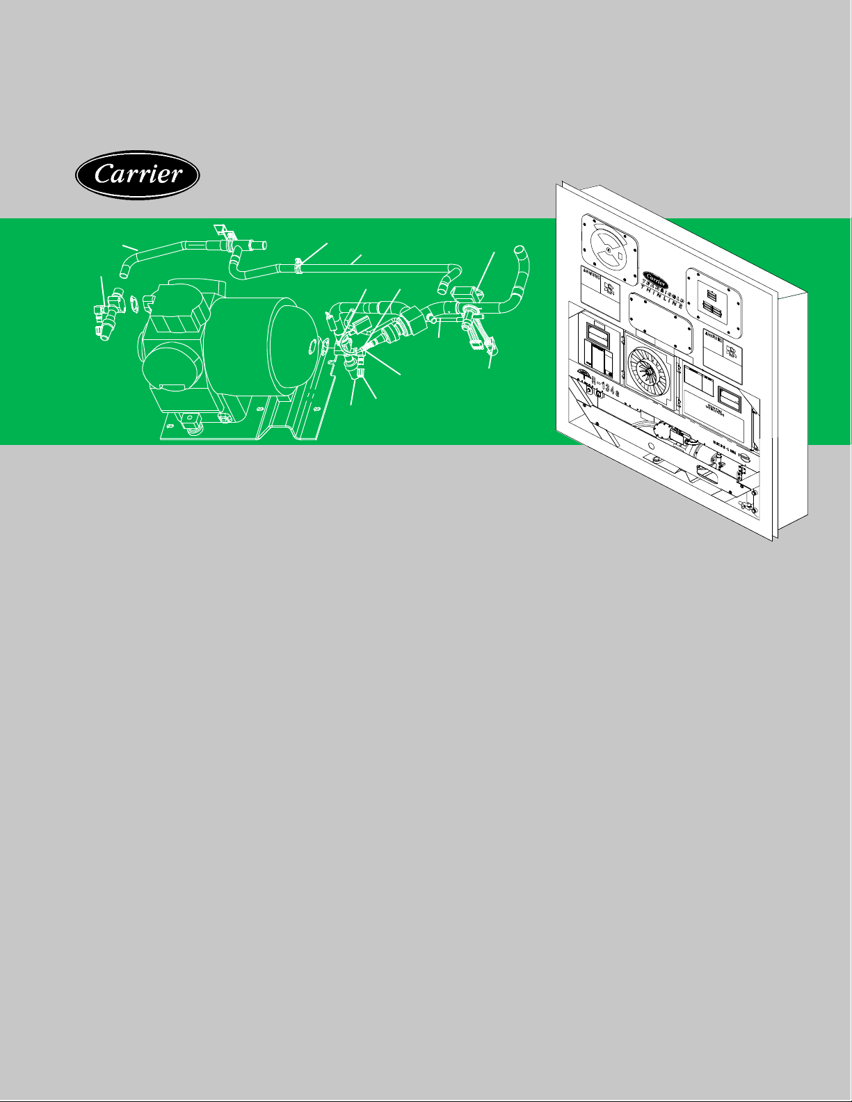
SERVICE PARTS LIST
69NT40--489--100 Series
EverFresh Controlled Atmosphere
Container Refrigeration Units
T--305PL Rev B Change 6/10
for
Page 2

SERVICE PARTS LIST
CONTAINER REFRIGERATION UNIT
EVERFRESH
CONTROLLED ATMOSPHERE
Model
69NT40-489-100 Series
Page 3

TABLE OF CONTENTS
PARAGRAPH NUMBER Page
1 QUICK LIST -- CLAMPS, FILTER--DRIER, FUSE, TY--RAPS, AND WIRE TERMINALS 1............
2 REFRIGERATION UNIT ASSEMBLY 2....................................................
2.1 REFRIGERATION UNIT -- AREA LOCATOR 2..........................................
2.2 RAIN GUTTERS 4..................................................................
2.3 HANDLES 5.......................................................................
2.4 CONTROL BOX DOOR 6............................................................
2.5 CONTROL BOX 8..................................................................
2.6 CONTROL BOX -- STD ELECTRICAL COMPONENTS, RM AND HOURMETER 10..........
2.7 CONTROL BOX -- EVAP FAN CAPABILITY, EBS and EDS, EBS ONLY and CFS 12..........
2.8 CONTROL BOX -- CONTROLLER MODULE SECTION AND SOFTWARE CARDS 14........
2.9 CONTROL BOX -- DISPLAY MODULE AND COMMUNICATIONS INTERFACE MODULE 17.
2.10 CONDENSER FAN MOTOR AND COIL 18..............................................
2.11 CONDENSER FAN GRILLE ASSEMBLY 20.............................................
2.12 COMPRESSOR TUBING 22..........................................................
2.13 RECEIVER 24.......................................................................
2.14 WATER--COOLED CONDENSER 26...................................................
2.15 SRS AND STS 28....................................................................
2.16 BACK PANEL ASSEMBLY -- OPTION 4, Aluminum HINGED 29...........................
2.17 UPPER FRESH AIR MAKE--UP AND ACCESS PANEL 30................................
2.18 EVAPORATOR FAN ASSEMBLY 32....................................................
2.19 EVAPORATOR COIL -- REAR PANELS REMOVED 34...................................
2.20 USDA OPTION 36...................................................................
2.21 COMPRESSOR MTG., GUARD, CRANKCASE AND DRAIN LINE HEATER COMPONENTS 38
2.22 COMPRESSOR GAUGES AND TRANSDUCERS 40.....................................
2.23 CABLE RESTRAINT COMPONENTS 42................................................
2.24 VOLTAGE CABLES 44...............................................................
2.25 AUTOTRANSFORMER KIT 46........................................................
2.26 LABELS AND DECALS 48..............................................................
3 INTERROGATOR AND ACCESSORIES 50
3.1 DATAREADER 50....................................................................
3.2 INTERROGATOR RECEPTACLE 52...................................................
4 COMPRESSOR ASSEMBLY 54...........................................................
5 CONTROLLED ATMOSPHERE EQUIPMENT ASSEMBLY 58.................................
5.1 CONTROLLED ATMOSPHERE EQUIPMENT -- AREA LOCATOR 58.......................
5.2 CONTROLLED ATMOSPHERE CONTROL BOX DOOR 60...............................
5.3 CONTROLLED ATMOSPHERE CONTROL BOX 62......................................
5.4 CONTROLLED ATMOSPHERE CONTROL BOX -- SHIELD REMOVED 64..................
5.5 CALIBRATION, GAS CHARGE AND PRESSURIZATION/GAUGE PORTS 66...............
5.6 EVAPORATOR FAN DECK 68.........................................................
5.7 EVAPORATOR -- BACK PANELS REMOVED 70.........................................
5.8 DRAIN SOLENOID VALVES 74........................................................
5.9 MEMBRANE AIR FILTER ASSEMBLY 76...............................................
5.10 AIR INTAKE FILTER 78...............................................................
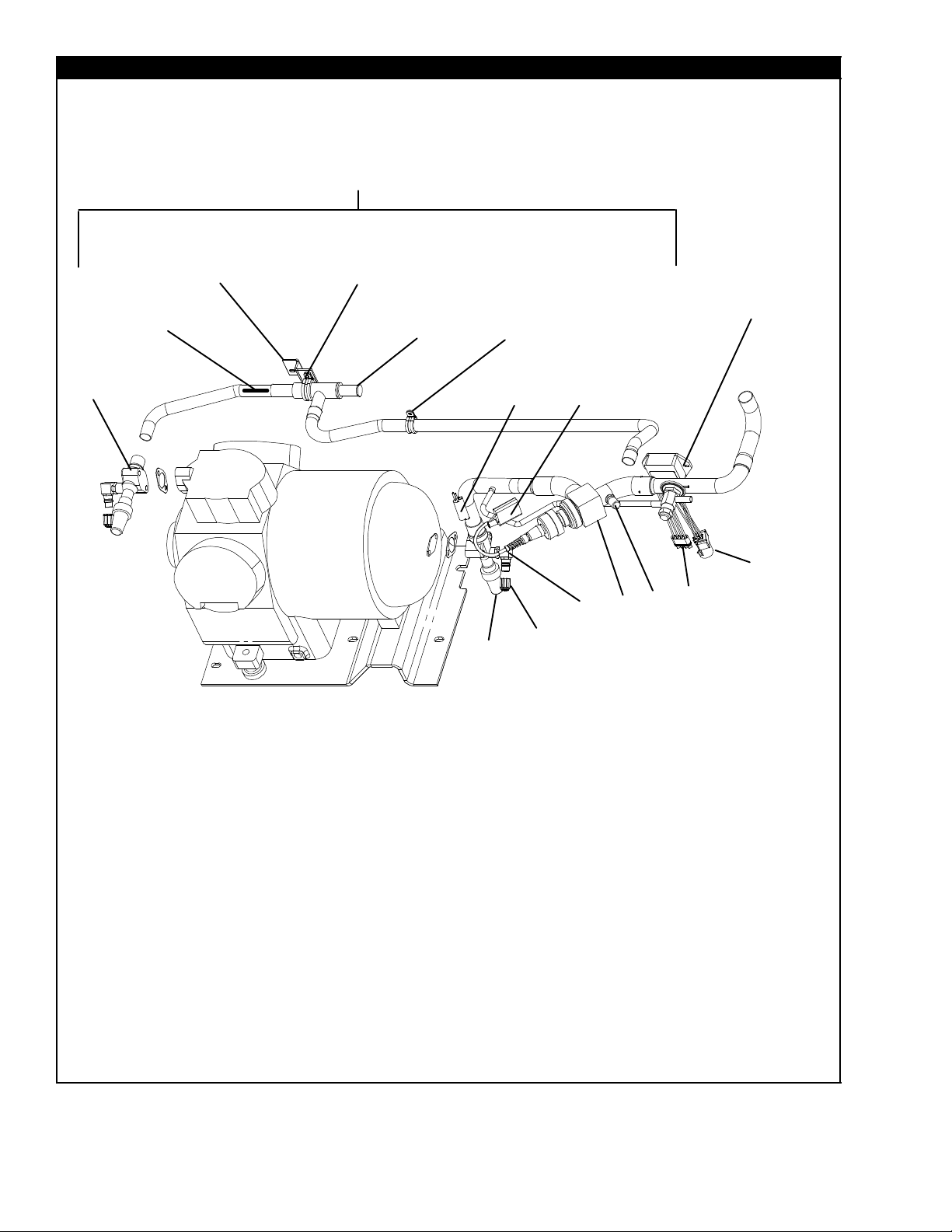
5.11 AIR COMPRESSOR Part Number 18--00052--03SV 80...................................
5.12 AIR COMPRESSOR Part Number 18--00099 82.........................................
.................................................
i T-305PL
Page 4

PARAGRAPH NUMBER
5.13 AIR COMPRESSOR MOUNTING 84...................................................
5.14 PRE--TRIP KIT AND DOOR INTERLOCK SYSTEM 86...................................
6 CONTROLLER CONFIGURATION 88......................................................
6.1 REFRIGERATION CONTROLLER/DATACORDER CONFIGURATION 88...................
7 TOOLS 89..............................................................................
Page
iiT-305PL
Page 5

INTRODUCTION
1 INTRODUCTION
The Carrier Transicold model 69NT40--489--100 series
units are of lightweight aluminum frame construction,
designed to fit in the front of a container and serve as the
container front wall.
2 CONFIGURATION IDENTIFICATION
Unit identification information is provided on a plate
located near the refrigeration compressor. The plate
provides the unit model number, the unit serial number
and the unit parts identification number (PID). The
model number identifies the overall unit configuration,
while the PID provides information on specific optional
equipment, factory provision to allow for field installation
of optional equipment, and differences in detailed parts.
Configuration identification for the models covered
herein are provided in the Carrier Transicold Container
Unit Matrix manual, publication T--300.
3 OPTION DESCRIPTIONS
Various options may be factory or field-fitted to the base
unit. These options are listed in the tables and described
in the following subparagraphs.
3.1 Battery
The refrigeration controller may be fitted with standard
replaceable batteries or rechargeable battery pack. The
unit is fitted with the EverFresh controlled atmosphere
option. The CA controller may be fitted with the same
battery option.
3.2 Dehumidification
The unit may be fitted with a humidity sensor. This
sensor allows setting of a humidity set point in the
controller. In the dehumidification mode, the controller
will operate to reduce internal container moisture level.
3.3 Control Box
The control box may be of aluminum or composite
material, and each type box may be fitted with a lockable
door.
3.4 Temperature Readout
The unit may be fitted with suction and discharge
temperature sensors. The sensor readings may be
viewed on the controller display.
3.5 Pressure Readout
The unit may be fitted with suction and discharge
pressure gauges, or suction and discharge transducers
or no pressure readout. The transducer readings may
be viewed on the controller display.
3.6 USDA
The unit may be supplied with fittings for additional
temperature probes, which allow recording of USDA
Cold Treatment data by the integral DataCORDER
function of the Micro--Link refrigeration controller.
3.7 Interrogator
Units that use the DataCORDER function are fitted with
interrogator receptacles for connection of equipment to
download the recorded data. Two receptacles may be
fitted; one accessible from the front of the container and
the other mounted inside the container (with the USDA
receptacles).
3.8 Remote Monitoring
The unit may be fitted with a remote monitoring
receptacle. This item allows connection of remote
indicators for COOL, DEFROST and IN RANGE.
Unless otherwise indicated, the receptacle is mounted
at the control box location.
3.9 Communications
The unit may be fitted with a communications interface
module. The communications interface module is a
slave module, which allows communication with a
master central monitoring station. The module will
respond to communication and return information over
the main power line. Refer to the ship master system
technical manual for further information.
3.10 Compressor, Refrigeration
The unit is fitted with a single-speed reciprocating
compressor.
3.11 Condenser Coil
The unit may be fitted with a 2-row or 4-row coil using
nominal 3/8 inch tubing, or a 3-row coil using 7mm
tubing. The required refrigerant charge is different for
each coil.
3.12 Autotransformer
An autotransformer may be provided to allow operation
on 190/230, 3-phase, 50/60 hertz power. The
autotransformer raises the supply voltage to the
nominal 380/460 volt power required by the base unit.
The autotransformer may also be fitted with an
individual circuit breaker for the 230 volt power.
If the unit is fitted with an autotransformer and
communications module, the autotransformer will be
fitted with a transformer bridge unit (TBU) to assist in
communications.
3.13 Gutters
Rain gutters may be fitted over the control box and
EverFresh control box to divert rain away from the
controls.
3.14 Handles
The unit may be fitted with handles to facilitate access to
stacked containers. These handles may include a fixed
handle (located at the right side of the unit) and/or
hinged handles at the left side and center (attached to
the condenser coil cover).
iii
T-305PL
Page 6

3.15 Water Cooling
The refrigeration system may be fitted with a watercooled condenser. The condenser is constructed using
copper--nickel tube for seawater applications. The
water-cooled condenser is in series with the air-cooled
condenser and replaces the standard unit receiver.
When operating on the water-cooled condenser, the
condenser fan is deactivated by either a water pressure
switch or condenser fan switch.
3.16 Back Panels
The refrigeration system may be fitted with either
aluminum or stainless steel back panels. Panels may be
fitted with access doors and/or hinge mounting.
3.17 460 Volt Cable
Various power cable and plug designs are available for
the main 460 volt supply. The plug options tailor the
cables to each customer’s requirements.
3.18 230 Volt Cable
Units equipped with an autotransformer require an
additional power cable for connection to the 230 volt
source. Various power cable and plug designs are
available. The plug options tailor the cables to each
customers requirements.
3.19 Cable Restraint
Various designs are available for storage of the power
cables. These options are variations of the compressor
section front cover.
3.20 Upper Air (Fresh Air Make Up)
The unit is fitted with an upper fresh air makeup
assembly. The openings may also be fitted with
screens.
3.21 Controlled Atmosphere
The controlled atmosphere system is of the two purity
type. This provides a second level of operation when
additional removal of carbon dioxide is required. All units
covered in this manual are fitted with the controlled
atmosphere option.
3.22 Arctic Mode
To improve operation in cold ambients, the unit may be
fitted with a crankcase heater and/or a condensate drain
line heater. The crankcase heater is operated before
start--up to warm the compressor oil and boil off any
liquid refrigerant that may be present in the crankcase.
The drain line heater is operated to prevent freezing of
the evaporator condensate drain system.
3.23 Humidification
The unit may be equipped with the Carrier Transicold
NatureFresh humidity management system. The
system includes a water tank, water pump, water
heater, and atomizer along with various control and
monitoring devices. It is designed to add additional
moisture into the supply air for control of cargo moisture
level. A separately bound manual covering operation
and parts for the CTD NatureFresh System is available
(see the following chart).
Manual
Number
T-297
Equipment
Covered
Humidity Management
System Option
Type of
Manual
Technical
Supplement
3.24 Power Correction
The unit may be fitted with a set of power factor
correction capacitors to assist in correction of
imbalance in current draw by the compressor.
3.25 Evaporator
Evaporator section options include a hermetic thermal
expansion valve with a choice of two sizes of heat
exchangers.
3.26 Evaporator Fan Operation
The units are fitted with Normal Evaporator Fan
Operation. Opening of an evaporator fan internal
protector will shut down the unit.
3.27 Labels
Operating Instruction and Function Code listing labels
will differ depending on the options installed. For
example, additional operating instructions are required
to describe start--up of a unit equipped with an
autotransformer. Where the labels are available with
additional languages, they are listed in the parts list.
3.28 Plate Set
Each unit is equipped with a tethered set of wiring
schematic and wiring diagram plates. The plate sets are
ordered using a seven digit base part number and a two
digit dash number. EverFresh controlled atmosphere
units have a second set of plates for the controlled
atmosphere system. These plate sets are numbered
and ordered in the same manner. (See Unit Matrix)
3.29 Controller
There are two controllers in the unit. The refrigeration
controller controls the temperature and the EverFresh
controller controls the Controlled Atmosphere
components. Replacement controllers may be ordered
as a universal unconfigured controller (without
configuration software) or configured.
3.30 Stepper Drive
All the units covered by this manual have suction
modulating valves, which act to control system capacity.
Units indicated as being fitted with “stepper drive” have
digital control motors fitted to the suction modulating
valve to open and close the valve in steps as required.
3.31 Condenser Grille
Two styles of condenser grilles are available -- direct
bolted grilles and hinged grilles.
3.32 Emergency Bypass
The unit may be equipped with switches to allow
emergency bypass of the controller. The EMERGENCY
BYPASS switch functions to bypass the controller in the
event of controller failure. The EMERGENCY
DEFROST switch functions to bypass the all controls
and place the unit in the defrost mode.
T-305PL
iv
Page 7

OPTION LEGEND
General
--
X Features that apply to model
P Factory Installation of Equipment to
Battery Codes
S Standard (throw away) Cells
R Rechargeable Cells
Control Box Codes
A Aluminum Box without Door Lock
AL Aluminum Box with Door Lock
C Composite Box without Door Lock
CL Composite Box with Door Lock
Pressure Readout Codes
G Factory Installed Pressure Gauges
T Factory Installed Pressure Transducers
SG Factory Installed Suction Pressure Gauge
USDA Codes
D Option D
V Option V
Interrogator Codes
1 Left Straight Mount
2 Right Mount
3 Box Mount
4 Left Mount
5 Left Angled Mount
6 Right Mount
Back Panel Codes
4 Hinged Panels
Communications Codes
1 Standard
2 HighDataRate
3 Chipset Modem
3l Chipset Modem Low Data Rate
3h Chipset Modem High Data Rate
Feature Not Applicable
Allow Field Installation
Compressor Codes
1R Single Speed Reciprocating
Condenser/Receiver Codes
2 Two Row Coil
3 Three Row (7mm) Coil
4 Four Row Coil
AutoTransformer Codes
1 Transformer Fitted
2 Transformer with CB2 Fitted
3 Transformer with CB2 and Receptacle
4 Transformer with CB2 and TBU
Gutter Codes
2 Standard Length Bolted Gutters
Handle Codes
1 Two Side and One Center
2 Two Side
3 One Center
4 One Right Side and Two Center
Thermometer Port Codes
1 Supply Air Port
2 Return Air Port
B Both Ports
Water Cooling Codes
W Water Pressure Switch
F Condenser Fan Switch
460 Volt Cable Codes
1 Option1
2 Option 2
3 Option 3
4 Option 4
5 Option 5
6 Option 6
7 Option 7
8 Option 8
9 Option 9
v
T-305PL
Page 8

230 Volt Cable Codes
1 Option 1
2 Option 2
3 Option 3
4 Option 4
5 Option 5
6 Option 6
7 Option 7
8 Option 8
9 Option 9
Cable Restraint Codes
1 Cable Door
2 Left Bungy Cord Only
3 J--Hook
4 Left and Right Bungy Cord
5 Left Bungy Cord with Left Extended Guard
6 Left and Right Bungy Cords with Extended
Guards
Upper Air Codes
2 Upper Fresh Air Installed
3 Upper Fresh Air Installed with Screen
Controlled Atmosphere
1 TransFresh
2 Carrier Transicold EverFresh System
Arctic Mode Codes
C Crankcase Heater
L Drain Line Heater
B Both Crankcase Heater and Drain Line Heater
Condenser Grille Codes
B Bolted Grille
H Hinged Grille
Evaporator Codes
1 Original Coil with Semi--Hermetic TXV and
Standard Heat Exchanger
Evaporator Fan Codes
1 Normal Evaporator Fan Operation
Label Codes
1 English
2 English / Spanish
Emergency Bypass Codes
B Emergency Bypass and Emergency Defrost
EB Emergency Bypass Only
Ordering Instructions
All orders and inquiries for parts must include: Parts Identification Number (PID), Model Number, Unit Serial Number,
Part Number, Description of part as shown on list, and Quantity required. Address all correspondence for parts to the
following address:
CARRIER TRANSICOLD DIVISION
Replacement Components Group, TR-20
P.O. Box 4805, Syracuse, New York 13221
or FAX to: (315) 432-3778
Letter Designations
The following letter designations are used to classify parts throughout this list:
A/R = As Required
N/A = Not Available
NS = Not shown in illustration
NSS = Not sold separately -- Order next higher assembly or kit
PID = Parts Identification Number -- essential to identify unit configuration.
PL = Purchase Locally
SST = Stainless Steel -- 300 Series unless otherwise specified.
SV = Suffix SV -- added to part number designates service replacement part.
T-305PL
vi
Page 9

1 QUICK LIST -- CLAMPS, FILTER--DRIER, FUSE, TY--RAPS, AND WIRE TERMINALS
PART NO. DESCRIPTION
34--00373--51 Clamp, Tube, 1/4, SST
34--00373--53 Clamp, Tube, 3/8, SST
34--00373--05 Clamp, Tube, 1/2, SST
34--00373--07 Clamp, Tube, 5/8, SST
34--00373--59 Clamp, Tube, 3/4, SST
34--00373--11 Clamp, Tube, 7/8, SST
34--00373--65 Clamp, Tube, 1--1/8, SST
34--00373--67 Clamp, Tube, 1--1/4, SST
34--00373--69 Clamp, Tube, 1--3/8, SST
34--00373--71 Clamp, Tube, 1--1/2, SST
22--00066--01 Connector, Butt End, Wire Range -- 22 to 16 AWG
22--00066--02 Connector, Butt End, Wire Range -- 16 to 14 AWG
22--00066--03 Connector, Butt End, Wire Range -- 12 to 10 AWG
22--00041--00 Connector, Closed End, Wire Range -- 22 to 14 AWG
22--00041--02 Connector, Closed End, Wire Range -- 18 to 10 AWG
66U1--7472--1 Filter--Drier
22--02336--02 Fuse, 5 Amp (F1 and F2)
22--02336--04 Fuse, 10 Amp (F3)
22--01140--01 Ring Terminal, #6, Wire Range -- 12 to 10 AWG
22--01140--02 Ring Terminal, #10, Wire Range -- 12 to 10 AWG
22--01140--04 Ring Terminal, 3/8, Wire Range -- 12 to 10 AWG
22--00119--04 Ring Terminal, 1/4, Wire Range -- 12 to 10 AWG
22--00120--04 Ring Terminal, #10, Wire Range -- 16 to 14 AWG
22--00120--07 Ring Terminal, 5/16, Wire Range -- 16 to 14 AWG
22--00121--07 Ring Terminal, #10, Wire Range -- 22 to 16 AWG
22--01139--04 Ring Terminal, 3/8, Wire Range -- 16 to 14 AWG
22--01141--01 Spade Terminal, 1/4 X 5/16, Wire Range -- 16 to 14 AWG
22--00595--01 Spade Terminal, 3/8, Wire Range -- 12 to 10 AWG
22--01106--00 Spiral Wrap, 1/4 Diameter X 25 Feet Long
22--01107--00 Spiral Wrap, 1/2 Diameter X 25 Feet Long
66U1--3803 Tube, Heat Shrink, 1/4 ID X 2--1/8 Long
66U1--3803--1 Tube, Heat Shrink, 1/2 ID X 2--3/4 Long
44--01043--05 Ty--Raps, 5--1/2 Inches Long
44--01043--07 Ty--Raps, 11.00 Inches Long
22--50007 Series Wire Markers
07--00345--00 Sealant, Pipe (Used to seal fittings on unit with R--134a)
07--00313--00 Cleaner, Coil
76--00397--00 Paint, Compressor Touch--Up, Blue
1
T-305PL
Page 10
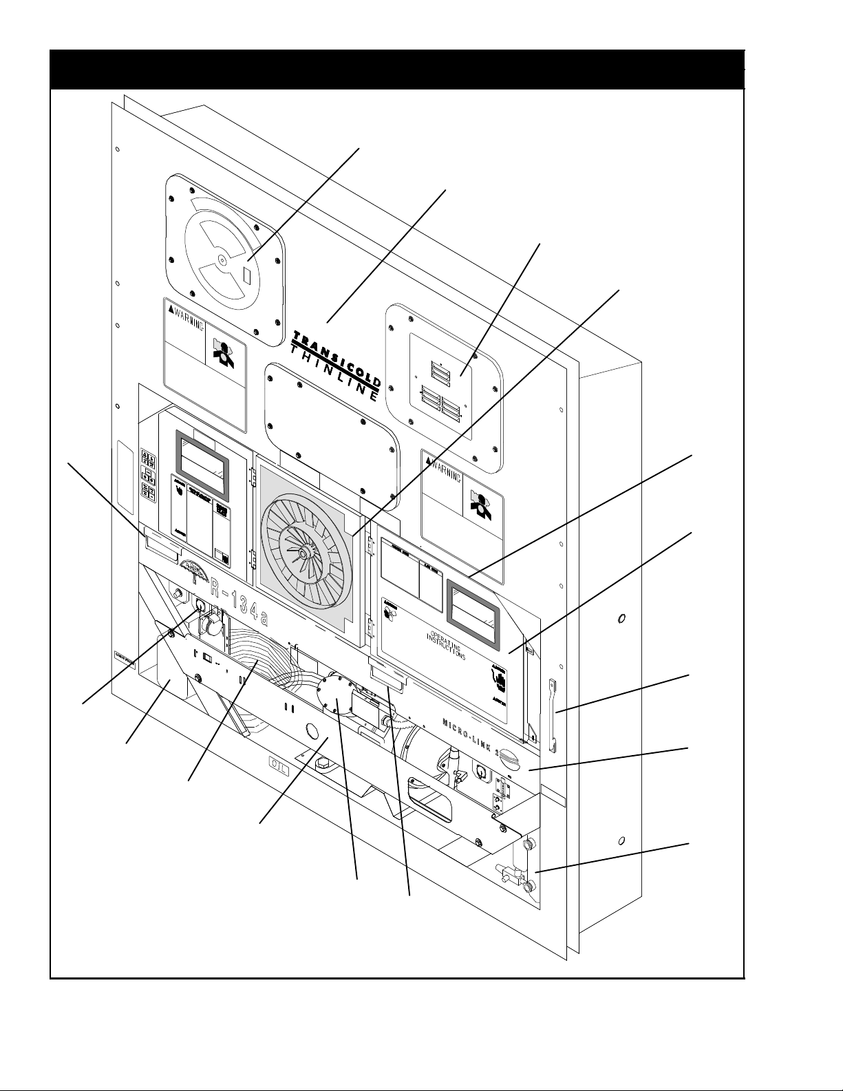
2 REFRIGERATION UNIT ASSEMBLY
2.1 REFRIGERATION UNIT -- AREA LOCATOR
2
Item 1, Controlled Atmosphere
Equipment, Refer to Section
3
4
5
5
9
17
16
14
15
13
7
8
9
10
11
12
9
2T-305PL
Page 11

2.1 REFRIGERATION UNIT -- AREA LOCATOR (Continued)
Item Section Number Area Description
1 Refer to Section 5 Controlled Atmosphere Equipment
2 Refer to Section 2.17 Upper Fresh Air Makeup and Access Panels
3 Refer to Section 2.26 Labels and Decals
4 Refer to Section 2.18 Evaporator Fan Assembly
5 Refer to Section 2.10 Condenser Fan Motor and Coils
6 Refer to Section 2.11 Condenser Fan Grille
7 Refer to Section 2.2 Rain Gutters
8 Refer to Section 2.4-- 2.9 Box, Control
9 Refer to Section 2.3 Handles
10 Refer to Section 2.10 Condenser Coil
11 Refer to Section 2.13 or 2.14 Receiver or Water-- Cooled Condenser
12 Refer to Sections 2.21 or 4 Compressor
13 Refer to Section 2.21 Guard, Compressor
14 Refer to Section 2.24 Power Cables
15 Refer to Section 2.24 Power Plugs
16 Refer to Section 2.25 Autotransformer
17 Refer to Section 3 Interrogator and Accessories
3
T-305PL
Page 12
2.2 RAIN GUTTERS
2
1
Item Part Number Description Qty
OPTION 2 -- STANDARD LENGTH
1 69NT35--3987 Gutter, Rain (Standard -- Right Side) 1
2 69NT35--7078 Angle, Rain Gutter (Left Side) 1
4T-305PL
Page 13
2.3 HANDLES
1
1
2
Item Part Number Description Qty
OPTION 1 -- TWO SIDE, ONE CENTER
1 69NT35--81 13 Handle, Fixed 2
2 69NT40--657-- 2 Handle, Hinged 1
OPTION 2 -- TWO SIDE
1 69NT35--81 13 Handle, Fixed 2
OPTION 3 -- ONE CENTER
2 69NT40--657-- 2 Handle, Hinged 1
OPTION 4 -- ONE RIGHT SIDE, TWO CENTER
1 69NT35--81 13 Handle, Fixed 1
2 69NT40--657-- 2 Handle, Hinged 2
5
T-305PL
Page 14
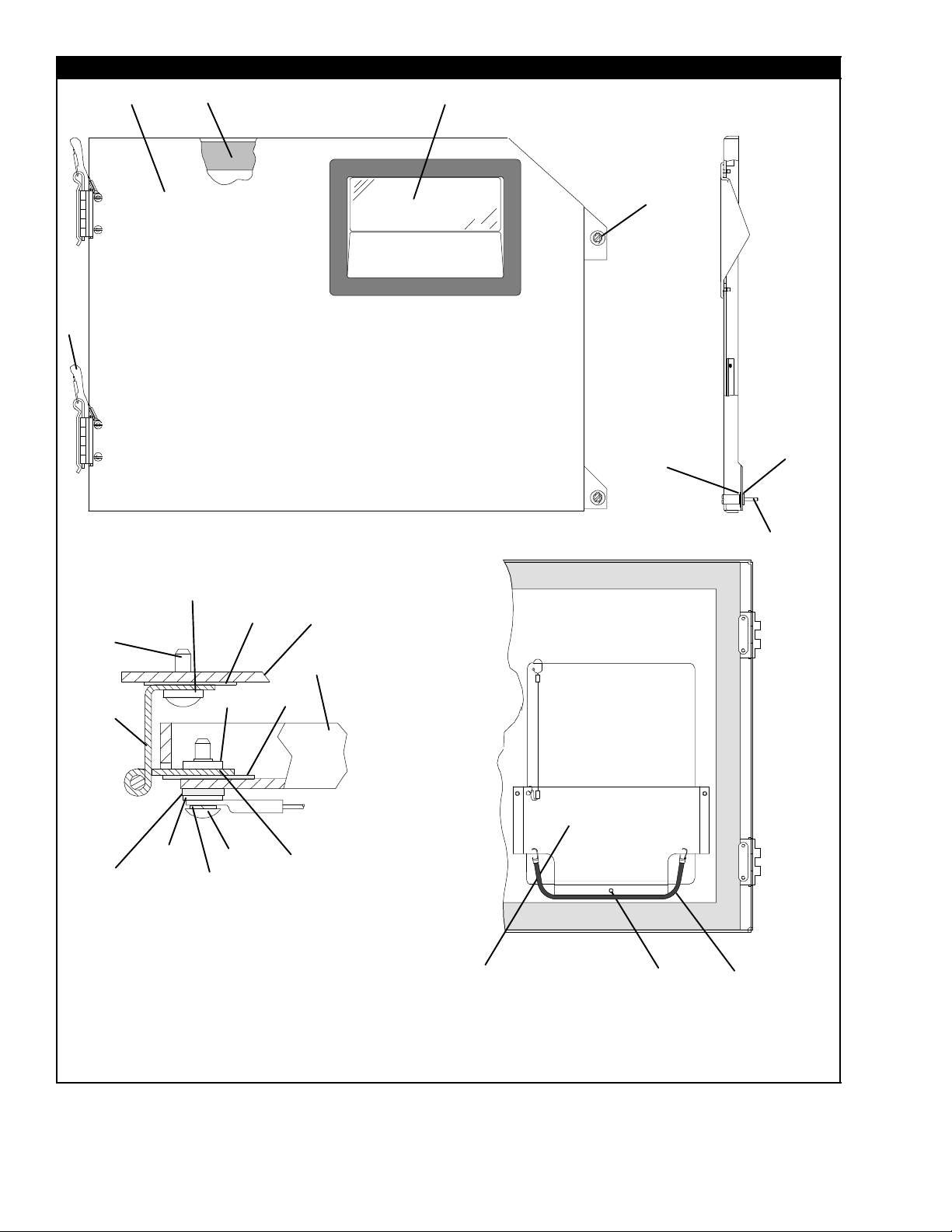
2.4 CONTROL BOX DOOR
12 4
10
6
5
7
18
16
7
19
13
9
11
12
14
15
Control Box
Control Box Door
17
8
6
5
Hinge Assembly -- Sectional View
17
Door Assembly -- Partial Back View
6T-305PL
18
15
11
19
22
Page 15

2.4 CONTROL BOX DOOR (Continued)
Item Part Number Description Qty
1 69NT42--688-- 7 Door Assembly -- Includes: 1
2 42--00270--02 Gasket, Door 1
3 58--04366--00SV Window and Gasket Assembly, Control Box Door, Lexan 1
4 34--06169--00 Washer, Retaining, SST 2
5 66U1--6811--8 Screw, Retaining, Panel, 0.300--0.625, SST 2
5 66U1--6811--15 Screw, Retaining, Wing, 0.300--0.625, SST 2
6 34--06053--00 Washer, Mylar, 0.25 ID X 0.80 OD 4
7 44--00300--01 Hinge, Half 1
8 44--00300--02 Hinge, Half 1
9 44--00300--03 Pin Assembly, with Tether 1
10 58--04101--01 Protector, Mylar (Hinge) (Not Needed with Composite Box) 2
11 34--01167--01 Retainer, Nut 2
12 58--04101--00 Protector, Mylar (Hinge) 2
13 66U1--2403--1 Screw, Truss Head, #10--24 X 3/4 Long, SST 4
14 66U1--5331--3 Washer, Lock, #10, SST 7
15 66U1--5321--8 Washer, Flat, #10, SST 7
16 34--06053--05 Washer, Mylar, 0.205 ID X 0.600 OD 4
17 68--13577--00 Pocket, Placard 1
18 34--00665--09 Locknut, Hex Head, #10--24, SST 3
19 34--06107--00 Rivet, Blind, 1/8 Diameter, Grip Range -- 0.188--0.250 3
20 66U1--5371--7 Screw, #10--24 X 1/2 Long, SST 4
21 66U1--5321--8 Washer, Flat, #10, SST 4
22 58--04346--00 Door Strap Kit 1
7
T-305PL
Page 16
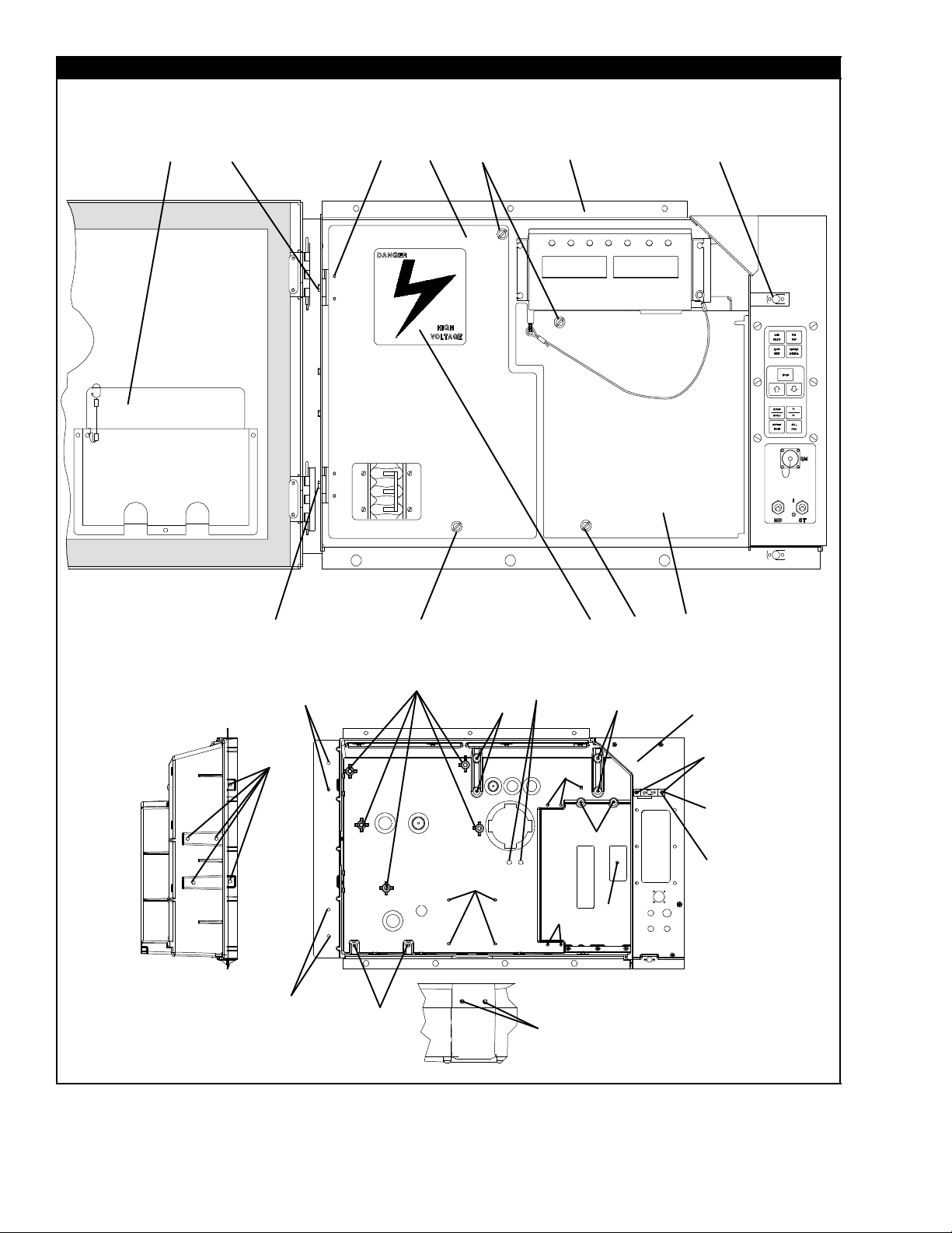
2.5 CONTROL BOX
1
3
4
6
22
7
8
5
9
12
13
14
15
2
24
26
5
9
21
26
23
22
22
OPTION C and CL -- COMPOSITE BOX
25
24
22
22
11
23
22
23
5
9
10
16
22
17
18
19
20
In Box
8T-305PL
Page 17
2.5 CONTROL BOX (Continued)
Item Part Number Description Qty
1 -- Plate, Schematic and Diagram (Refer to T--300, Container Unit Matrix) 1
2 66U1--2403 Screw, Truss Head, #10--24 X 1/2 Long, SST 2
3 69NT43--125-- 1 Shield, High Voltage (Plastic) -- Includes: 1
4 44--00343--00 Hinge 2
5 34--00928--02 Rivet, Blind, 1/8 Diameter, Grip Range -- 1/8--3/16, SST 4
6 34--50015--00 Stud and Retainer Package -- Includes: 4
7 NSS Stud, Fastener 1
8 NSS Retainer, Fastener Stud 1
9 34--06139--03 Receptacle 4
10 69NT43--124-- 4SV Shield, Low Voltage (Lexan) with Tether 1
11 62--03957--02 Label, Danger--High Voltage 1
OPTION A and AL, Aluminum CONTROL BOX
12 86--04237--03 Control Box, Standard Aluminum 1
13 68--12791--00 Bracket, Lock (See Note 1) 1
34--01142--01 Receptacle, Retaining 1
14
34--01152--02 Receptacle, Retaining (See Note 2) 1
34-- 00928--01 Rivet, Blind, 1/8 Diameter, Grip Range 1/16 -- 1/8 2
15
34-- 00928--03 Rivet, Blind, 1/8 Diameter, Grip Range 3/16 -- 1/4 (See Note 2) 2
NOTES
1. The bracket is welded to the control box -- order Item #11 for locking plate.
2. When Item #11 is used, 34--01152--02 and rivets, 34--00928--03 are to be used in the upper door location.
OPTION C and CL -- COMPOSITE CONTROL BOX
16 58--04668--01 Control Box, Standard Composite 1
69NT35--6272 Bracket, Non--Locking 1
17
69NT35--2287 Bracket, Locking (See Note 3) 1
18 34--01142--01 Receptacle, Retaining 1
34-- 00928--01 Rivet, Blind, 1/8 Diameter, Grip Range 1/16 -- 1/8 2
19
34-- 00928--02 Rivet, Blind, 1/8 Diameter, Grip Range 1/18 -- 3/16 (See Note 4) 2
20 66U1--2403 Screw, Truss Head, #10--24 X 1/2 Long, SST 2
NS 76--00724--00SV Crack, Chip and Hole Repair Kit 1
NS 76--50084--00SV Insert Repair Kit -- Includes: 1
21 34--06231--01 Insert -- 17.53 X 9.91 mm (0.690 X 0.390 in) 1/4--20 Threads -- NSS 10
22 34--06231--03 Insert -- 15.88 X 6.35 mm (0.625 X 0.250 in) 10--24 Threads -- NSS 10
23 34--06231--04 Insert -- 25.15 X 7.54 mm (0.990 X 0.297 in) 10--24 Threads -- NSS 10
24 34--06231--05 Insert -- 10.16 X 9.53 mm (0.400 X 0.375 in) 10--24 Threads -- NSS 10
25 34--06231--06 Insert -- 12.70 X 9.91 mm (0.500 X 0.390 in) 1/4--20 Threads -- NSS 10
26 34--06231--07 Insert -- 9.53 X 6.76 mm (0.375 X 0.266 in) 10--24Threads -- NSS 10
NS 02--00082--00 Durabond Epoxy -- NSS 1
NS 07--00390--00 Static Mixing Tube -- NSS 1
NS 07--00391--00 Application Gun -- Required for Insert Repair 1
NOTES
3. The bracket is bolted to the control box -- order 69NT35--2287 for locking bracket.
4. When 69NT35--2287 is used, 34--00928--02, rivet, is to be used in the upper door location.
9
T-305PL
Page 18
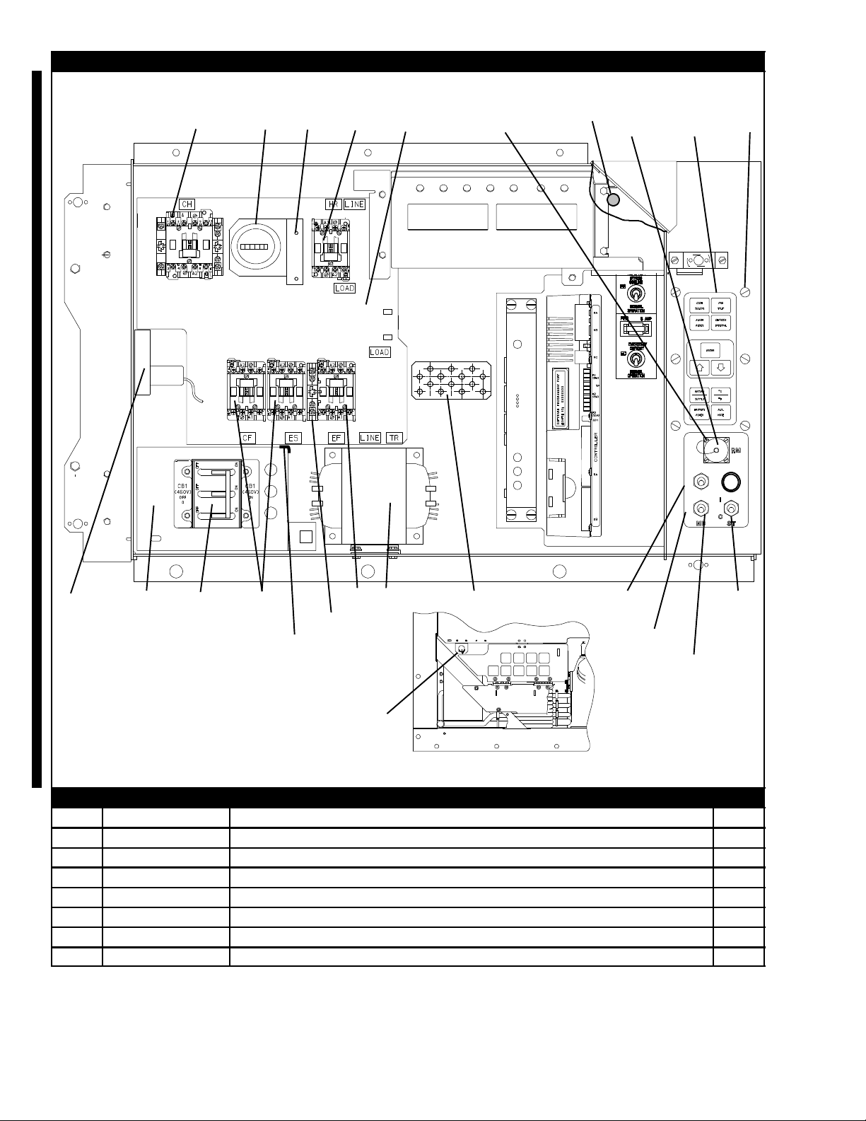
9.6 CONTROL BOX -- SHIELDS REMOVED, STD ELECTRICAL COMPONENTS, RM AND HOURMETER
3
6
1
2
4
6
7
9
10
8
40
41
42
31
36
37
38
39
30
13
32
33
34
35
5
20
26
27
28
19
20
25
22
23
24
6
7
21
18
7
19
20
17
29
16
or
43
11
12
6
14
15
44
45
Remote Monitoring ---
Lower/External Mounting
HOURMETER
Item Part Number Description Qty
1 66U1--3823
Hourmeter 1
2 66U1--6651--15 Screw, Pan Head, #4--40 X 3/4 Long, SST
68-- 12496--00 Bracket, Hourmeter 1
3
66U1-- 5381 Screw, Hex Head, #10--24 X .50 Long, SST 2
4
10-- 00431--07 Contactor, Compressor (CH) (30 Amp) 1
5
34-- 06243--00 Screw, Pan Head, (Thread Cutting) #8-- 32 X 3/4 Long, SST 10
6
10-- 00431--06 Contactors, (CF), (HR) and (EF and ES) (12 Amp) 4
7
13
14
3
10T-305PL
Page 19
9.6 CONTROL BOX -- SHIELDS REMOVED, STANDARD ELECTRICAL COMPONENTS (Continued)
Item Part Number Description Qty
68-- 13427--00SV Panel, Contactor -- Includes: 1
8
58-- 00967--00 Spacer (Used with Sheet Metal Control Box Only) 5
9
34-- 00655--08 Screw, Hex Head, 1/4-- 20 x 1.00 Long, SST 4
10
34-- 00928--01 Rivet, Blind, 1/8 Diameter, Grip Range -- 1/16 -- 1/8 6
11
34-- 01142--01 Receptacle 1
12
10-- 01129--07SV Switch, Toggle (On--Off) 1
13
66U1-- 9752 Seal, Bushing 1
14
10-- 01129--10 Switch, Toggle (MDS) 1
15
58-- 04145--01 Plate, Switch A/R
68-- 14796--00 Plate, Switch (Start Only) NT--1200 and Up A/R
16
68-- 14796--02 Plate, Switch (Start and Defrost LED), NT-- 1200 and Up A/R
68-- 14796--05 Plate, Switch (Start and MDS), NT--1200 and Up A/R
69NT41-- 982-- 3 Plate, Ground 1
17
10-- 00332--07 Transformer, Base Unit 1
18
10-- 00332--05 Transformer, Base Unit (Do NOT use with Composite Box) 1
66U1-- 5371-- 7 Screw, Hex Head, #10-- 24 X 1/2 Long, SST A/R
19
66U1-- 5321-- 8 Washer, Flat, #10, SST A/R
20
10-- 00431--02 Contact, Auxiliary 1
21
34-- 00663--07 Washer, Lock, #6, SST 4
22
66U1-- 7842-- 13 Circuit Breaker -- 460 VAC, 25 Amp, (CB1) 1
23
66U1-- 6651-- 4 Screw, Pan Head, #6-- 32 X 3/8 Long, SST 4
24
69NT35-- 6278 Bracket, Circuit Breaker 1
25
10-- 00439--00 Transformer, Current Sensing (CS) 1
26
66U1-- 5371-- 10 Screw, Hex Head, #10--24 X 1.00 Long, SST 2
27
66U1-- 5321-- 8 Washer, Flat, #10, SST 2
28
66CH1--1172-- 46 Trim, Flexible (85 Feet Long, Cut to Length) A/R
29
30 79--66669--00 Pad, Key -- Includes: 1
31 NSS Dot, Indicator (Green) -- See Note 1
32 NSS Gasket (Between Keypad and Keypad Plate Assembly 1
33 NSS Plate Assembly, Keypad Mounting 1
34 34--66629--05 Screw, Pan Head, #10--24 X 3/4 Long, SST (Use with Composite Box) 6
35 34--06212--10 Washer, Mylar, 0.205 ID X 0.600 OD 6
NOTE: If unit is not already fitted with green indicator dot (Item 31) on upper right corner of control box door,
install dot as illustrated after the replacement of this key pad.
REMOTE MONITORING (STANDARD LOCATION)
22-- 02341--00 Receptacle, Remote Monitoring (RM) 1
36
22-- 02368--00 Plug, Remote Monitoring 1
37
22-- 02341--01 Cap and Tether, Receptacle Assembly 1
38
66U1-- 6835 Gasket, Remote Monitoring Receptacle 1
39
34-- 00848--10 Screw, Round Head, #4--40 X 5/8 Long, SST 4
40
66U1-- 5321-- 6 Washer, Flat, 0.125 ID, SST 4
41
34-- 00667--05 Nut, Self Locking, #4--40, SST 4
42
58-- 04145--00 Plate, Switch, with RM A/R
68-- 14796--03 Plate, Switch, with RM NT--1200 and up A/R
43
68-- 14796--06 Plate, Switch with RM and MDS, NT-- 1200 and Up A/R
11
T-305PL
Page 20
REMOTE MONITORING (LOWER LEFT/EXTERNAL LOCATION)
22-- 01889--00 Receptacle, Remote Monitoring (RM) 1
44
69NT40-- 222 Bracket 1
45
9.7 CONTROL BOX -- SHIELDS REMOVED, EV AP FAN CAPABILITY, EBS and EDS, EBS ONLY and CFS
19
5
20
21
8
1
2
3
4
Bottom Right Corner of Unit
6
9
10
8
EBS and EDS
7
13
11
12
6
9
10
8
6
9
10
8
EBS Only
14
15
16
7
17
18
12T-305PL
Page 21

2.7 CONTROL BOX -- SHIELDS REMOVED, EVAP FAN CAPABILITY (Continued)
Item Part Number Description Qty
OPTION 1 -- NORMAL EVAPORATOR FAN OPERATION
See Section 2.6 Items 6 and 7 for correct contactor placement
OPTION B -- EMERGENCY BYPASS SWITCH AND EMERGENCY DEFROST SWITCH
1 10--00416--00 Module, Emergency Bypass 1
2 66U1--5371--6 Screw, Machine Hex Head, #10-- 24 X 0.75 Long, SST 2
3 34--06053--05 Washer, Mylar, 0.205 ID X 0.600 OD 2
4 66U1--5321--8 Washer, Flat, #10, SST 2
58-- 04145--09 Plate, Switch (With Light Location) 1
58-- 04145--07 Plate, Switch (With Light Location, with RM) 1
68-- 14796--01 Plate, Switch (With Light Location) NT--1200 and up A/R
5
68-- 14796--02 Plate, Switch (With Light Location) NT--1200 and up A/R
68-- 14796--04 Plate, Switch (With Light Location, with RM) NT-- 1200 and Up A/R
6 10--01129--07SV Switch, T oggle 2
7 68--12544--01 Bracket 1
8 34--06223--00 Screw, Captive Washer, #10--24 X .56 Long, SST 2
9 10--01129--20 Hex Nut 2
10 66U1--9752 Seal, Bushing 2
11 22--01455--02 Holder Assembly, Fuse 1
12 22--02336--02 Fuse, 5 Amp 1
13 62--02874--01 Label, EB and ED 1
14 22--00518--01 Base,PilotLight 1
15 22--00519--03 Light Assembly, Pilot 1
16 22--00049--01 Lamp, 24VDC 1
OPTION EB -- EMERGENCY BYPASS SWITCH ONLY
1 10--00416--00 Module, Emergency Bypass 1
2 66U1--5371--6 Screw, Machine, Hex Head, #10--24 X 0.75 Long, SST 2
3 34--06053--05 Washer, Mylar, 0.205 ID X 0.600 OD 2
4 66U1--5321--8 Washer, Flat, #10, SST 2
6 10--01129--07SV Switch, T oggle 1
7 68--12544--01 Bracket 1
8 34--06223--00 Screw, Captive Washer, #10--24 X .56 Long, SST 2
9 10--01129--20 Hex Nut 1
10 66U1--9752 Seal, Bushing 1
17 62--02874--00 Label, EB Upper 1
18 62--02874--02 Label, EB Lower 1
OPTION F -- CONDENSER FAN SWITCH
19 10--00298--01 Switch, Toggle (CFS) 1
20 66U1--9752 Seal, Bushing 1
58-- 04145--06 Plate, Switch (With Extra Switch Location) 1
21
13
T-305PL
Page 22
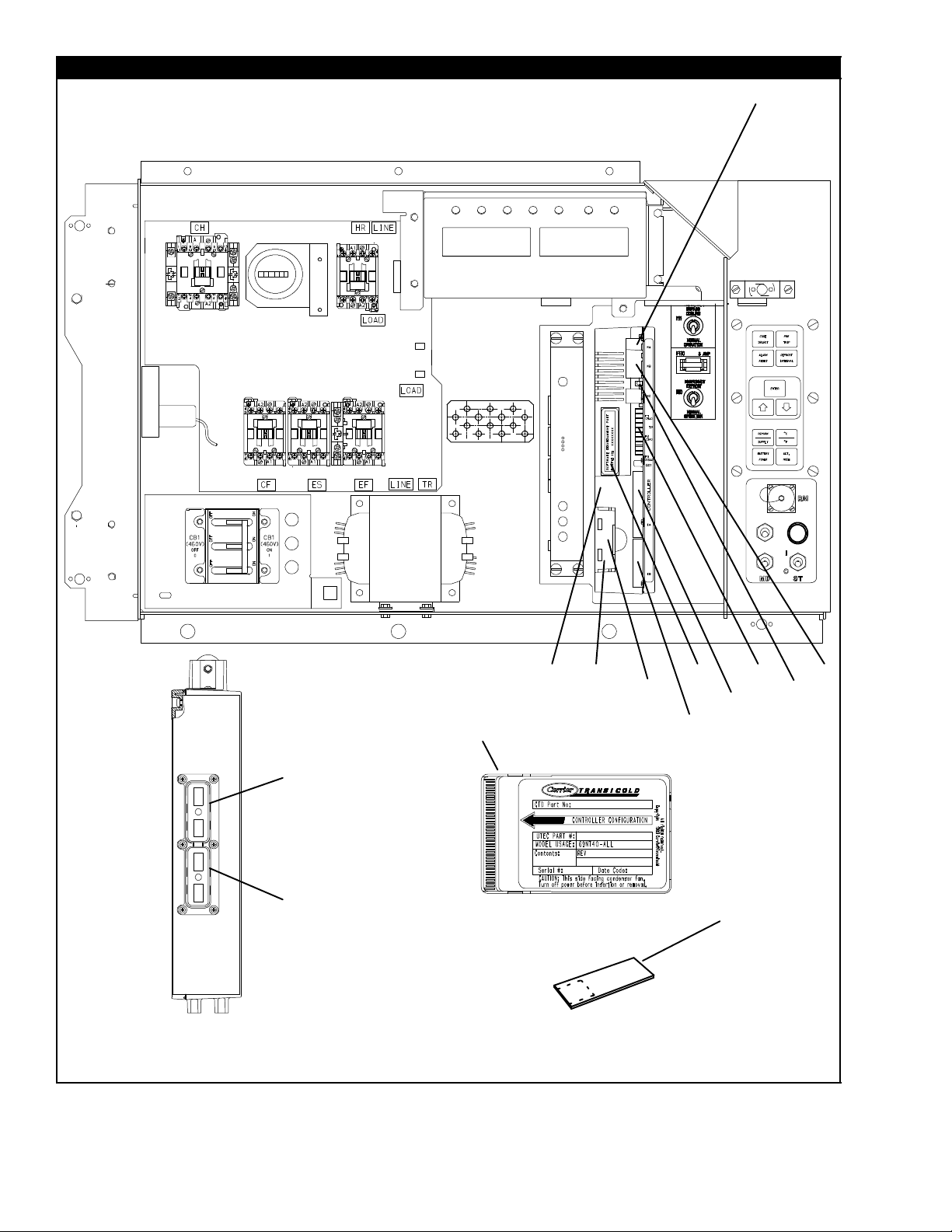
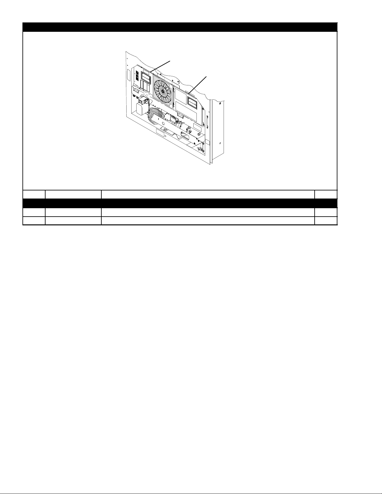
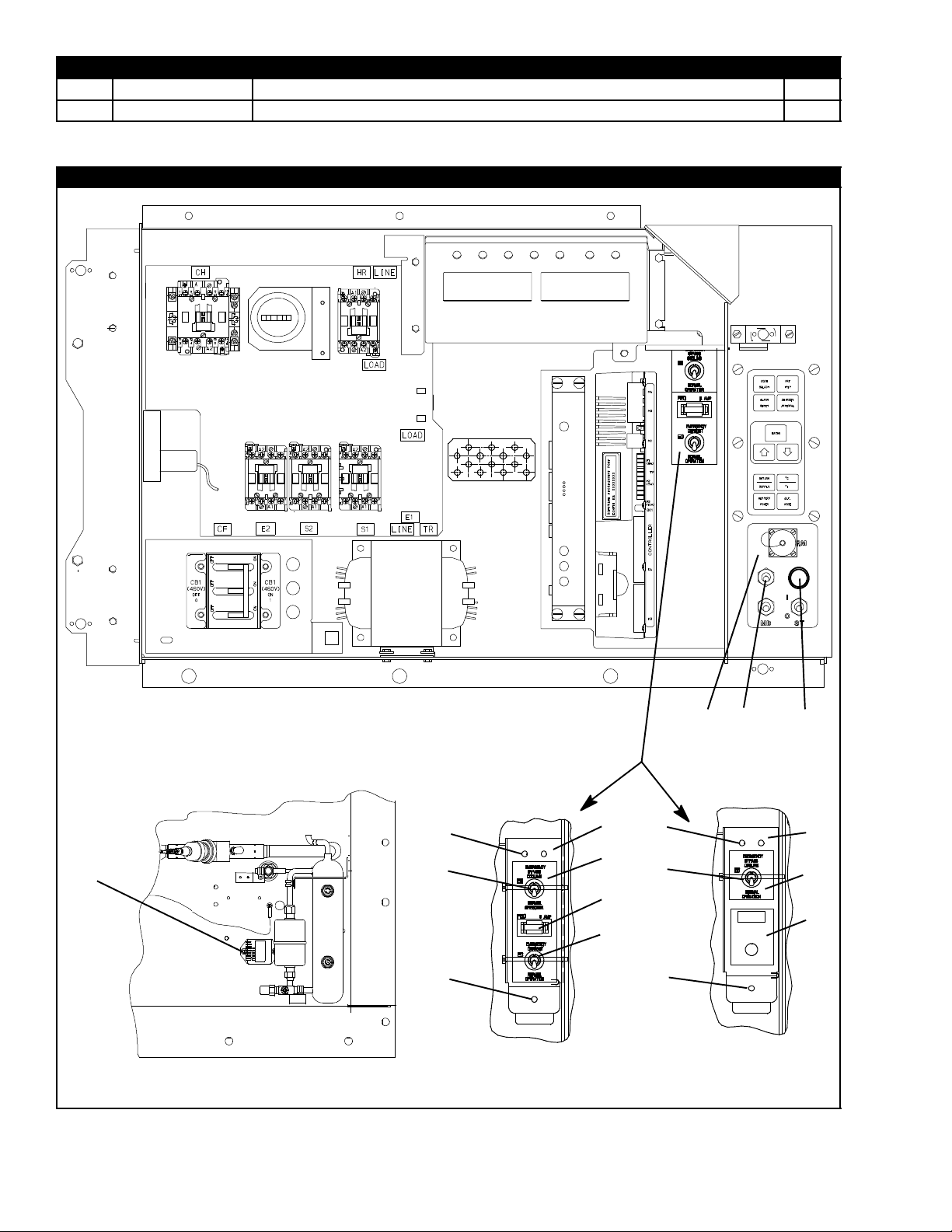
2.8 CONTROL BOX -- CONTROLLER MODULE SECTION AND SOFTWARE CARDS
16
9
10
11
12
13
10
12
View -- Back of Controller/DataCORDER Module
1
21
2
22
3
4
8
20
15
7
14
19
5
6
17
18
14T-305PL
Page 23

2.8 CONTROL BOX -- CONTROLLER MODULE SECTION AND SOFTWARE CARDS (Continued)
Item Part Number Description Qty
1 -- Module, Controller/DataCORDER -- RefertoSection6-- Includes: --
2 66U1--5371--7 Screw, Hex Head, #10--24 X 1/2 Long, SST 1
3 69NT35--2692 Washer, Fender, 0.063 Thick, SST 1
4 58--01184--00 Retainer, Screw, 0.141 ID 1
5 22--02336--04 Fuse, 10 Amp (F3) 3
6 22--02336--02 Fuse, 5 Amp (F1 and F2) 1
7 62--02719--00 Label, Controller/DataCORDER Port 1
8 12--00397- -00/5124 Card, Controller/DataCORDER Operation Software 1
NS 12--00402--xx Card, Configuration Software 1
9 22--01777--00SV Connector (EC A--K) -- 30-- Pin 1
10 22--01777--03 Socket, 20 AWG 35
11 22--50100--00 Socket, 18 AWG 4
12 22--01777--04 Plug, Sealing 21
13 22--01777--01SV Connector (EC L--Y) -- 30--Pin 1
14 22--01556--02 Connector (KA) -- 14--Pin 1
15 22--01556--01 Connector (KB) -- 10--Pin 1
NS 22--01621--23 Connector (KP) -- 9--Pin (Connects to Ribbon Cable) 1
16 22--01622--01 Connector (MA) -- 12--Pin 1
17 22--01622--02 Connector (MB) -- 16--Pin 1
18 22--01622--00 Connector (MC) -- 8--Pin 1
NS 09--00369--00SV Battery, Real Time Clock, (Within the Controller) 1
NS 22--50157--00 Wire Harness, Controller to Current Sensing Transformer) 1
NS 22--01713--06 Wire Harness, Display Module to Controller/DataCORDER Module 1
NS 62--02735--00 Label, Warning, Don’t use 12--00327 ! --(Located on Control Box Behind
the Controller/DataCORDER Module)
NS 62--02738--05 Label, Warning, 5108 Series -- (Located on the Bottom Panel of the Control
Box Between the Transformer and the Communications Interface Module)
19 76--50141--00 PC Card Adapter and Cover (For Use with 12--00594 series ML3 Cards) 1
OPTION R -- RECHARGEABLE BATTERY PACK
20 30--00407--02SV Battery Pack -- Controller/DataCORDER Module 1
OPTION S -- STANDARD CELLS
21 PL Battery (AA) 6
22 30--00407--00 Cover, Controller Battery 1
1
1
15
T-305PL
Page 24
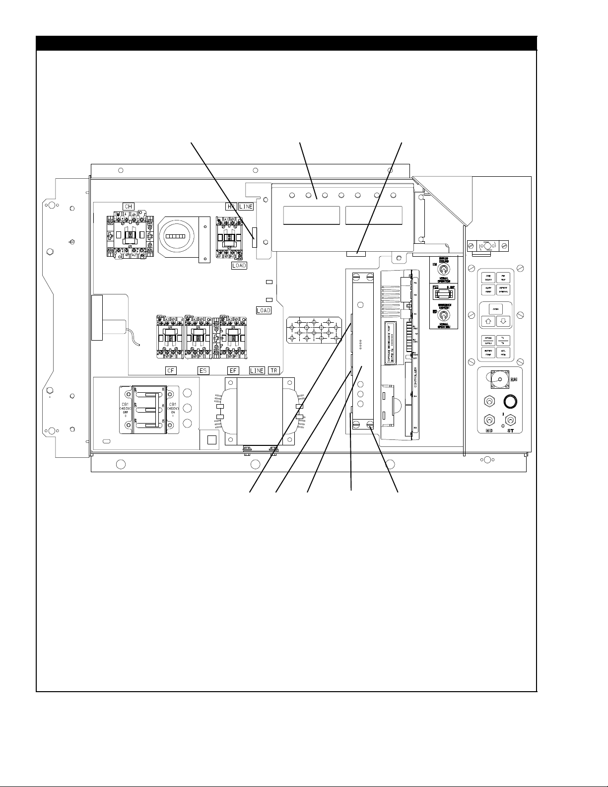
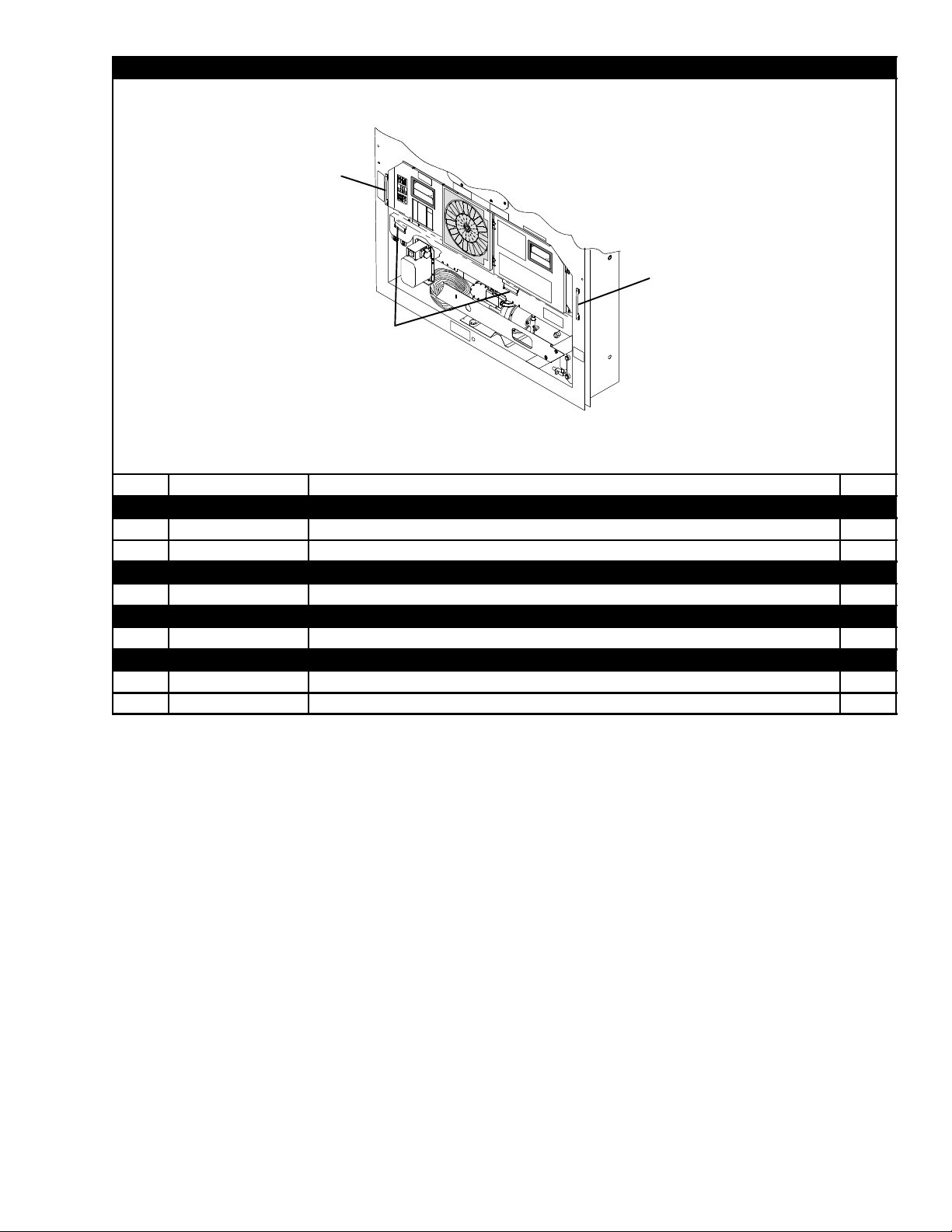
2.9 CONTROL BOX -- DISPLAY MODULE AND COMMUNICATIONS INTERFACE MODULE SECTION
1
45
2
3
6
7
9
10
11
16T-305PL
8
12
13
Page 25

2.9 CONTROL BOX -- DISPLAY MODULE AND COMMUNICATIONS INTERFACE MODULE SECTION
(Continued)
Item Part Number Description Qty
1 12--00433--00RP Module, Display 1
2 66U1--5371--7 Screw, Hex Head, #10--24 X 1/2 Long, SST 4
3 69NT35--2692-- 4 Washer, Fender, 0.063 Thick, SST 4
4 22--01621--03 Connector (MK), 9--Pin 1
5 22--01621--02 Connector (MB), 16--Pin 1
6 22--02396--03 Connector (CIC), 7--Pin 1
7 22--02396--02 Connector (CIB), 3--Pin 1
8 22--01556--00 Connector (CIA), 7--Pin 1
NS 22--01713--02 Wire Harness, Keypad to Display Module 1
OPTION 1 -- COMMUNICATIONS INTERFACE MODULE -- STANDARD
9 12--00573--00SV Module, Communications Interface -- Includes: 1
10 66U1--3442--2 Stud, Fastener, 1/4 Turn, 0.705 Long, SST 4
11 66U1--9212--1 Retainer, Push--on 4
12 34--06223--00 Screw, Captive Washer #10--24 X 0.56, SST 4
13 58--01184--00 Retainer, Screw 0.75 OD 4
OPTION 2 -- COMMUNICATIONS INTERFACE MODULE -- HIGH DATA RATE
9 12--00573--00SV Module, Communications Interface -- Includes: 1
10 66U1--3442--2 Stud, Fastener, 1/4 Turn, 0.705 Long, SST 4
11 66U1--9212--1 Retainer, Push--on 4
12 34--06223--00 Screw, Captive Washer #10--24 X 0.56, SST 4
13 58--01184--00 Retainer, Screw 0.75 OD 4
OPTION 3 -- COMMUNICATIONS I NTERFACE MODULE -- CHIPSET MODEM
9 12--00573--00SV Module, Communications Interface -- Includes: 1
10 66U1--3442--2 Stud, Fastener, 1/4 Turn, 0.705 Long, SST 4
11 66U1--9212--1 Retainer, Push--on 4
12 34--06223--00 Screw, Captive Washer #10--24 X 0.56, SST 4
13 58--01184--00 Retainer, Screw 0.75 OD 4
OPTION 4 -- COMMUNICATIONS INTERFACE MODULE -- LOW DATA RATE
9 12--00275--19SV Module, Communications Interface -- Includes: 1
10 66U1--3442--2 Stud, Fastener, 1/4 Turn, 0.705 Long, SST 4
11 66U1--9212--1 Retainer, Push--on 4
12 34--06223--00 Screw, Captive Washer #10--24 X 0.56, SST 4
13 58--01184--00 Retainer, Screw 0.75 OD 4
17
T-305PL
Page 26
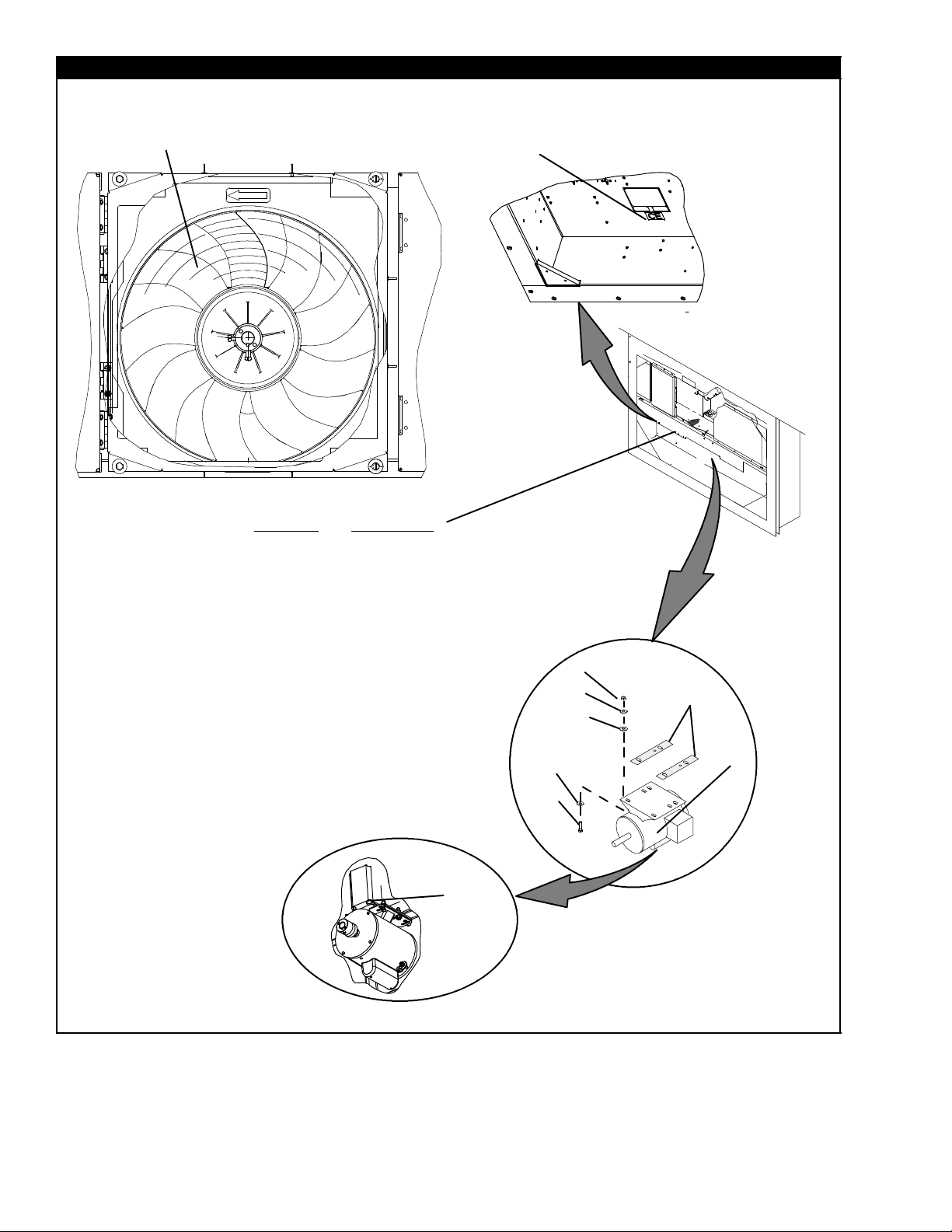
2.10 CONDENSER FAN MOTOR AND COIL
1
Option 3 or Option 2, 4
16
17
18
19
20
21
22
16
17
23
24
25
2
12
13
14
15
11
7
8
9
8
10
3
4
5
6
18T-305PL
Page 27

2.10 CONDENSER FAN MOTOR AND COIL (Continued)
Item Part Number Description Qty
1 38--00585--00 Fan, Condenser 1
2 62--02785--00 Label, CE 1
3 54--00586--20 Motor, Condenser -- Includes: 1
4 04--50029--00 Bearing 2
5 22--01997--05 Pin A/R
6 22--01997--10 Pin, Grounding A/R
7 34--00667--12 Nut, Self--Locking, 5/16--18 4
8 34--01181--01 Washer, Flat 8
9 34--06053--02 Washer, 0.375 ID X 1.000 OD 4
10 69NT35--6112 Protector, Condenser Fan Motor Mounting 2
11 66U1--5361 Screw, Cap HXHD, 5/16--18 X 1.25 4
12 69NT35--3452 Shim 1
13 69NT35--3452--1 Shim 1
14 69NT35--3452--2 Shim 1
15 69NT35--3452--3 Shim 1
OPTION 2 -- TWO ROW CONDENSER COIL
Use Option 4 for 2--Row Coil Replacement
OPTION 3 -- THREE ROW (7MM) CONDENSER COIL
68--13455--00 Cover, Condenser Coil, Blue Includes: 1
16
68--13455--03 Cover, Condenser Coil, White Includes: 1
58--04480--00 Bumper (For Use With Uncoated Center Handles) A/R
17
58--04481--00 Plug (For Use with Coated Handles or Units with no Center Handle) A/R
18 81--01575--00SV Coil, Condenser(Copper), 7MM 3--Row -- Includes Mylar Washers 1
19 66CH1--1172--16 Trim, Flexible 2
20 69NT35--8693--7 Protector (Apply Between Frame and Coil and Coil Cover) 4
21 69NT35--8693--10 Protector (Apply Between Frame and Coil and Coil Cover) 2
22 58--04026--41 Protector,Mylar (Apply Between Coil and Coil Cover, RH and LH Sides) 2
OPTION 4 -- FOUR ROW (3/8”) CONDENSER COIL
68--13201--01 Cover, Condenser Coil, Blue Includes: 1
16
69NT43--148--4 Cover, Condenser Coil, White Includes: 1
58--04480--00 Bumper (For Use with Uncoated Center Handles) A/R
17
58--04481--00 Plug (For Use with Coated Handles or Units with no Center Handle) A/R
23 69NT43--202-- 10SV Coil, Condenser (Copper), 4--Row -- Includes Mylar Washers 1
24 69NT35--8703 Protector (Apply Between Frame and Coil and Coil Cover) 4
25 58--04026--10 Protector,Mylar (Apply Between Coil and Coil Cover, RH and LH Sides) 2
19
T-305PL
Page 28
2.11 CONDENSER FAN GRILLE ASSEMBLY
234 51
234 5
1
9
13
16
9
14
15
17
1918 OR
8
7
10
11
6
12
8
1
2
3
BOLTED CONDENSER FAN GRILLE
Item Part Number Description Qty
OPTION B -- BOLTED CONDENSER FAN GRILLE, STANDARD PARTS
1 34--06051--36 Rivnut, 1/4--20 A/R
2 34--06053--03 Washer, 0.250 ID X 1.000 OD A/R
3 69NT35--2692-- 1 Washer, Fender, 1/4 A/R
4 34--00663--11 Washer, Lock, 1/4 Spring A/R
5 66U1--5361--25 Screw, Cap HXHD, 1/4--20 X 0.75 A/R
BLUE PANEL
-- 79--66635--00 Grille and Venturi Assembly, Blue -- Includes: 1
6 68--12635--05 Panel Venturi 1
7 86--04637--00 Grille Assembly 1
8 34--00928--07 Rivet, Blind 8
9 62--11273--00 Label, Rotation 1
WHITE PANEL
-- 79--66635--01 Grille and Venturi Assembly, White -- Includes 1
6 68--12635--22 Panel Venturi 1
7 86--04637--02 Grille Assembly 1
8 34--00928--07 Rivet, Blind 8
9 62--11273--00 Label, Rotation 1
ORANGE PANEL
-- 79--66635--02 Grille and Venturi Assembly, Orange -- Includes 1
6 68--12635--06 Panel Venturi 1
7 86--04637--01 Grille Assembly 1
8 34--00928--07 Rivet, Blind 8
9 62--11273--00 Label, Rotation 1
5
4
OPTION B
8
8
HINGED CONDENSER FAN GRILLE
OPTION H
8
18
OR
13
14
15
19
20T-305PL
Page 29

2.11 CONDENSER FAN GRILLE ASSEMBLY (Continu ed)
Item Part Number Description Qty
OPTION H -- HINGED CONDENSER FAN GRILLE, STANDARD PARTS
8 34--00928--07 Rivet, Blind 8
10 58--04101--07 Protector 4
11 44--00374--00 Hinge 2
12 34--06179--00 Screw, HXHD, Sems #10--24 x 7/16 4
13 34--06169--00 Washer, Retaining, SST 2
14 34--06053--03 Washer, Mylar, 1/4 ID X 1.00 OD 4
15 69NT35--2692--1 Washer, Fender, 1/4, SST 2
BLUE PANEL WITH SLOTTED SCREW
Use Standard Parts with Items Below:
-- 79--66635--03 Grille and Venturi Assembly, Blue, Slotted Screw -- Includes 1
16 68--12635--03 Panel, Venturi 1
17 86--04637--00 Grille Assembly 1
18 66U1--6811--8 Screw, Retaining, SST 2
WHITE PANEL WITH SLOTTED SCREW
Use Standard Parts with Items Below:
-- 79--66635--04 Grille and Venturi Assembly, White, Slotted Screw -- Includes 1
16 68--12635--21 Panel, Venturi 1
17 86--04637--02 Grille Assembly 1
18 66U1--6811--8 Screw, Retaining 2
ORANGE PANEL WITH SLOTTED SCREW
Use Standard Parts with Items Below:
-- 79--66635--05 Grille and Venturi Assembly, Orange, Slotted Screw -- Includes 1
16 68--12635--04 Panel, Venturi 1
17 86--04637--01 Grille Assembly 1
18 66U1--6811--8 Screw, Retaining 2
BLUE PANEL WITH PHILLIPS SCREW
Use Standard Parts with Items Below:
-- 79--66635--06 Grille and Venturi Assembly, Blue, Phillips Screw -- Includes 1
16 68--12635--03 Panel, Venturi 1
17 86--04637--00 Grille Assembly 1
19 66U1--6811--12 Screw, Retaining 2
WHITE PANEL WITH PHILLIPS SCREW
Use Standard Parts with Items Below:
-- 79--66635--07 Grille and Venturi Assembly, White, Phillips Screw -- Includes 1
16 68--12635--21 Panel, Venturi 1
17 86--04637--02 Grille Assembly 1
19 66U1--6811--12 Screw, Retaining 2
ORANGE PANEL WITH PHILLIPS SCREW
Use Standard Parts with Items Below:
-- 79--66635--08 Grille and Venturi Assembly, Orange, Phillips Screw -- Includes 1
16 68--12635--04 Panel, Venturi 1
17 86--04637--01 Grille Assembly 1
19 66U1--6811--12 Screw, Retaining 2
21
T-305PL
Page 30
2.12 COMPRESSOR TUBING
11
14
16
17
22
21
12
14
15
18
14
13
7
14
15
16
17
6
23
8
10
3
20
19
5
1
9
2
4
22T-305PL
Page 31

2.12 COMPRESSOR TUBING (Continued)
Item Part Number Description Qty
1 14--00263--00 Valve, Stepper Motor -- Includes: 1
2 14--00263--20 Piston and Motor Assembly -- Includes: 1
3 22--02392--03 Connector (To Power Pack) 1
NS 22--02393--01 Pin, 18--20 Gauge (Used on 22--02392--03) 4
NS 22--02394--03 Seal (Used on 22--02392--03) 4
4 14--00263--23 O--Ring 1
5 14--00263--22 Cap 1
6 Valve, Service (Discharge) -- See Section 4.3 1
7 14--00204--02 Valve, Discharge Pressure Regulator (DPRV) 1
8 -- Valve, Service (Suction) -- See Section 4.3 1
9 40--00542--00 Elbow, Adapter (R134a) 1
10 40--00520--02 Cap, M8 X 1.00, Nylon 1
11 69NT41--702 Bracket Assembly 1
12 66U1--3632--24 Clamp, Cushion, 1.18 Diameter 1
13 34--00373--11 Clamp, Cushion, 0.88 Diameter 1
14 66U1--5381--1 Screw, Hex Head, #10--24 X 0.75 Long, SST 4
15 34--06053--00 Washer, Mylar, 0.25 ID X 0.80 OD 3
16 66U1--5321--8 Washer , Flat, #10, SST 3
17 34--06053--05 Washer, Mylar, .205 ID X .60 OD 3
18 10--00388--00 Power Pack, Stepper Motor -- Includes: 1
19 22--01585--04 Connector (To Valve) 1
20 22--01836--00 Connector (To Harness) 1
21 81--01482--00 Tubing assembly 1
NS 22--01566--01 Socket (Used on 22--01585--04) 4
NS 22--02393--00 Pin (Used on 22--01830--00) 4
NS 22--02394--02 Seal (Used on 22--01835--00, 22--01585-- 04 and 22--01830--00) A/R
NS 22--01835--00 Connector (On Harness to Drive) 1
NS 22--01566--00 Pin (Used on 22--01835--00) 5
REFRIGERATION TEMPERATURE SENSORS
22 12--01105--02 Sensor, Thermistor (CPDS) 1
23 12--01104--05 Sensor, Thermistor (CPSS) 1
23
T-305PL
Page 32

2.13 RECEIVER
20
27
28
29
25
26
23
24
4
31
5
6
32
1
9
10
11
30
19
20
21
2
3
14
7
20
21
22
8
9
10
11
33
15
16
17
18
34
12
13
24T-305PL
Page 33

2.13 RECEIVER (Continued)
Item Part Number Description Qty
1 69NT43--403-- 2 Receiver, Electro--Coated Modular, Copper -- Includes: 1
2 14--00220--01 Glass, Sight, with Red Balls, 1/2--14 NPT 1
3 14--00221--01 Indicator, Moisture--Liquid 1
14--01032--14 Plug, Fusible, 3/8 NPT, Brass 1
4
14--00215--06 Disc, Rupture, 3/8 NPT, Alternate 1
NS 22--02448--00SV Connector, Female (Located on Wire Harness) 1
5 12--00352--00 Transducer, Condenser Pressure (CPT) 1
6 EC39DM062 Valve, Schrader 1
7 14--00341--02SV Filter--Drier with O--Rings 1
8 69NT43--277 Bracket, Liquid Line Valve 1
9 66U1--5361--25 Screw, Hex Head, 1/4--20 X 3/4 Long, SST A/R
10 66U1--5321--7 Washer, Flat, 1/4, SST 3
11 34--06053--00 Washer, Mylar, 0.25 ID X 0.80 OD 4
12 40--00520--01 Coupling, M15, Brass -- Includes: 1
13 40--00520--03 Cap, Service Port 1
14 14--00221--00 Valve, Liquid Line 1
15 66U1--5361--7 Bolt, Hex Head, 3/8--16 X 1.00 Long, SST 1
16 AU11JR241 Washer, Lock, 3/8, SST 1
17 66U1--5321--5 Washer, Flat, 3/8, SST 1
18 34--06053--02 Washer, Mylar, 0.375 ID X 1.00 OD 1
19 34--00373--05 Clamp, Cushion, 1/2 Diameter 1
20 66U1--5371--6 Screw, Machine, Hex Head, #10--24 X 0.75 Long, SST 3
21 34--06053--05 Washer, Mylar, .205 ID X .60 OD 4
22 34--00373--07 Clamp, Cushion, 5/8 Diameter 1
23 69NT43--420 Bracket Assembly, Quench Valve 1
24 34--00928--09 Rivet, Blind, 5/32 Diameter, Grip Range -- 1/8--1/4, SST 2
25 66U2--1132--1 Connector 1
26 66U1--3803 Heat Shrink 1
27 34--00373--54 Clamp, Cushion, 0.44 Diameter 1
28 34--06053--03 Washer, Mylar, 0.25 ID X 1.00 OD 1
29 14--00212--03SV Valve, Quench, Thermostatic Expansion -- Includes: 1
NS 14--00212--21 Kit, Repair -- Includes: 1
NS NSS Power Head 1
30 58--04026--23 Protector, Mylar 1
31 12--00495--02SV Sensor, Ambient Thermistor (AMBS) 1
32 DE40BA203 Tee, Reducing 1/2 X 1/2 X 3/8 1
33 -- See Section 5.9 for Sensor Assembly and Related Parts -34 40--00501--50 Cap, Service Valve 1
25
T-305PL
Page 34

2.14 WATER--COOLED CONDENSER
37
38
20
40
12
22
23
24
42
43
44
39
21
41
30
31
27
28
29
25
26
43
44
45
43
44
45
11
1
2
6
19
18
17
3
Item Part Number Description Qty
-- 69NT42--914 Kit, Condenser/Receiver (For Field Installation) -- See NOTE -- Includes: 1
1 69NT42--914-- 1 Condenser/Receiver -- Includes: 1
2 14--00220--00 Sight Glass with Red Balls, 1/2 NPT 1
3 58--00956--00 Protector, Mylar 2
4 58--00957--00 Protector, Mylar 1
5 66U1--2763--5 Coupling (Water--In) 1
6 66U2--1142 Cap, Dust 1
7 40--01129--00 Coupling, Self--Draining -- Includes: 1
7 66U1--2763--6 Coupling Assembly, Socket -- Includes: 1
8 42--50000--00 Seal, O--Ring 1
9 66U2--1152 Cap, Dust (Use with 40--01129--00) 1
10 79--01757--00 Cap Assembly (Use with 66U1--2763--6) 1
11 12--01071--01SV Switch,Water Pressure Option W 1
12 14--00215--05 Disc, Rupture, 3/8 NPT 1
7
8
9
5
14
16
32
33
34
35
36
13
15
4
26T-305PL
Page 35

2.14 WATER--COOLED CONDENSER (Continued)
Item Part Number Description Qty
13 66U1--5361--7 Bolt, Hex Head, 3/8--16 X 1.00 Long, SST 1
14 66U1--5321--5 Washer, Flat, 3/8, SST 1
15 AU11JR241 Washer, Lock, 3/8, SST 1
16 34--06053--02 Washer, Mylar, 3/8 ID X 1.00 OD 1
17 66U1--5361--25 Screw, Cap, Hex Head, 1/4--20 X 3/4 Long, SST 2
18 66U1--5321--7 Washer, Flat, 1/4, SST 2
19 34--06053--00 Washer, Mylar, 1/4 ID X 13/16 OD 2
20 -- See Section 2.15 for Sensor Assembly and Related Parts --
-- 76--00677--00 Accessory Kit, Water--Cooled Condenser Tubing -- Includes: --
21 06DA403--844 Valve, Schrader 1
22 12--00352--00 Transducer, Condenser Pressure (CPT) 1
23 69NT41--477 Tube Assembly -- Includes: 1
24 40--00555--06 Tee, 1/2 X 1/2 X 3/8 NPT , Brass 1
25 14--00341--02SV Filter--Drier with O--Rings 1
26 69NP20--1031 Clamp, Filter--Drier -- Includes: 1
NS 58--50014--00 Gasket (16 Feet, Cut to Length) 1
-- 69NT41--497 Tube Assembly -- Includes: 1
27 66U1--8552--2 Valve, Liquid Line -- Includes: 1
28 40--00086--04 Cap, Flare, 1/4 1
29 17--21002--01 Cap, Valve 1
30 40--00520--01 Coupling, M15, Brass -- Includes: 1
31 40--00520--03 Cap, Service Port 1
32 68--12368--00 Bracket 1
33 66U1--5371--6 Screw, Hex Head, #10--24 X 3/4 Long, SST 2
34 34--06053--05 Washer, Mylar, 0.205 ID X 0.600 OD 2
35 69NT41--487 Tube Assembly -- Includes: 1
36 14--01092--03 Indicator, Liquid--Moisture, Brass 1
37 69NT43--420 Bracket Assembly 1
38 34--00928--09 Rivet, Blind, 5/32 Diameter, Grip Range -- 1/8--1/4 2
39 14--00212--03SV Valve, Quench, Thermostatic Expansion -- Includes: 1
NS 14--00212--21 Kit, Repair -- Includes: 1
NS NSS Power Head 1
40 12--00495--02SV Sensor, Ambient Thermistor (AMBS) 1
41 DE40BA203 Tee, Reducing, 1/2 X 1/2 X 3/8 1
42 34--00373--54 Clamp, Cushion, 0.44 Diameter 1
43 34--06053--03 Washer, Mylar, 0.25 ID X 1.00 OD 3
44 66U1--5371--6 Screw, Machine Hex Head, #10--24 X 0.75 Long, SST 3
45 34--00373--07 Clamp, Cushion, 0.62 Diameter 2
NOTE
Must order tubing accessory kit 76--00677--00 when ordering P/N 69NT42--914 for field installation on units
provisioned for a water--cooled condenser.
27
T-305PL
Page 36

2.15 SRS AND STS
2
3
2
3
1
(STS)
1
(SRS)
45
Item Part Number Description Qty
1 12--00395--01SV Sensor Assembly (STS and SRS) 1
2 58--04277--00SV Cap, Probe -- Includes: 2
3 58--04278--00 Grommet NSS 2
4 58--04279--00 Cover, Probe 1
5 58--04276--00 Holder, Probe 1
6 66U1--5321--7 Washer , Flat, 1/4, SST 2
7 66U1--5371--7 Screw, Machine, Hex Head, #10--24 X 0.50 Long, SST 2
28T-305PL
6
7
Page 37

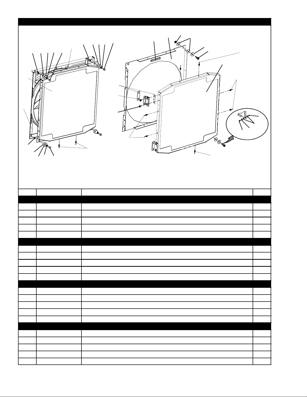
2.16 BACK PANEL ASSEMBLY -- OPTION 4, Aluminum HINGED
10
11
13
10
12
13
9
2
1
2
3
4
5
6
5
Item Part Number Description Qty
1 69NT43--1 16 Grille, Top 1
2 34--00928--09 Rivet, Blind, 5/32 Diameter, Grip Range -- 1/8--1/4 37
3 69NT41--942-- 4 Panel Assembly, Upper -- Includes: 1
NS NSS Drain Pan, Side 2
NS NSS Drain Pan, Center 1
4 42--00334--00 Gasket (Location -- Behind Upper Panel) 1
5 34--00928--02 Rivet, Blind, 1/8 Diameter, Grip Range -- 1/8--3/16 46
6 34--00928--03 Rivet, Blind, 1/8 Diameter, Grip Range -- 3/16--1/9 3
68--13475--00 Panel, Bottom, (Painted) 1
7
68--13475--08 Panel, Bottom, (Unpainted) 1
68--13475--01 Panel, Bottom (Provision for USDA Location), (Painted) 1
8
68--13475--09 Panel, Bottom (Provision for USDA Location), (Unpainted) 1
NS 66U1--8075 Gasket (25--foot, Cut to Length) A/R
9 69NT35--3282 Hinge 4
10 34--01150--30 Washer, Retaining 14
11 34--01150--06 Stud, 1/4 Turn, 1.03 Long 6
12 34--01150--03 Stud, 1/4 Turn, 0.97 Long 8
13 34--01150--31 Receptacle, Retaining 14
5
78
5
6
29
T-305PL
Page 38

2.17 UPPER FRESH AIR MAKE--UP AND ACCESS PANEL
Option 2 or 3
1
6
19
20
21
18
10
7
2
3
5
4
Back of Fresh Air Panel
8
15
14
9
16
17
11
13
12
See Section 5.10
5
4
6
30T-305PL
Page 39

2.17 UPPER FRESH AIR MAKE--UP AND ACCESS P ANEL (Continued)
Item Part Number Description Qty
OPTION 2 EVAPORATOR FAN ACCESS PANEL -- WITH FRESH AIR MAKEUP
79--01694--00 Panel, Fresh Air Make-- up with Retaining Washers -- Includes: A/R
1
79--01695--00 Panel with Fresh Air Makeup -- Includes: 1
2 42--00296--01 Gasket 1
3 42--00327--00 Gasket, -- 0.26 X 0.50 Half--Round 1
4 34--00662--1 1 Washer, Flat, 1/4, SST 8
5 34--06053--00 Washer, Mylar, 1/4 ID X 0.80 OD 8
6 34--06154--00 Screw, Hex Head, 1/4--20 X 1.00 Long -- TIR 8
7 66U1--2552--185 Gasket, 0.75 X 1.5 X 16.63 1
8 -- Label, Fresh Air (See Section 2.26 for Language Selection) 1
9 62--02783--00 Label, Fresh Air 1
OPTION 3 WITH FRESH AIR MAKEUP AND SCREENS -- USE ALL OF OPTION 2 AND ITEM BELOW
10 58--04251--00 Screen, Medfly 2
HEATER ACCESS PANEL
11 79--01697--07SV Panel, Access -- Includes: 1
12 42--00296--00 Gasket 1
13 66U1--8115 Gasket, Access Panel 1
5 34--00662--1 1 Washer, Flat, 1/4, SST 8
6 34--06053--00 Washer, Mylar, 1/4 ID X 0.80 OD 8
7 34--06154--00 Screw, Hex Head, 1/4--20 X 1.00 Long -- TIR 8
STUD ASSEMBLY KITS (REPLACEMENT)
14 74--00201--01 Kit, Gasket and Stud Assembly (See NOTE 2) -- Includes: 1
15 42--00407--00 Gasket (One Piece) 1
16 74--00201--02 Kit, Disc and Stud Assembly (See NOTE 1) -- Includes: 1
17 NSS Stud Assembly, 5/16--18 1
18 34--06185--01 Screw, Machine Pan Head, #8--32 X 1/2 Long, SST 1
19 34--06053--19 Washer, Mylar, 1.00 OD X 0.312 ID 1
20 66U1--5321--13 Washer, Flat, 5/16, SST 1
21 66U1--5362--2 Nut, Wing, 5/16--18, SST 1
NOTES
1. Disc and stud assembly kit, which will modify stud to 5/16- -18, also includes new disc and gasket.
2. Must order 74- -00201- -01 stud assembly kit, which will modify stud to 5/16- -18 and include 42--00407- -01
(one- -piece) gasket.
31
T-305PL
Page 40

2.18 EVAPORATOR FAN ASSEMBLY
EFM -- 2 (Location)
EFM-- 1 (Location)
12
11
4
3
2
1
2
3
4
5
7
8
9
6
10
32T-305PL
Page 41

2.18 EVAPORATOR FAN ASSEMBLY (Continued)
Item Part Number Description Qty
1 69NT40--476 Mounting Bracket, Evaporator Fan Assembly 4
2 66U1--5321--5 Washer , Flat, 3/8, SST 24
3 AU11JR241 Washer, Lock, 1/4, SST 24
4 66U1--5361--7 Bolt, Hex Head, 3/8--16 X 1.00 Long, SST 24
5 54--00513--00SV Motor, Evaporator Fan (Two Speed) -- Includes: 2
6 PL Key, 3/16 Square X 1--38 Long, SST 1
NS 54--00122--21 Bearing 2
NS 22--50087--00 Capacitor 1
NS 54--50044--00 Relay, Motor 1
NS 54--00521--22 Capacitor, Low Speed, 5 mF -- used ONL Y with 54--00513--00/74899 1
NS 22--50087--00 Capacitor, Low Speed, 15 mF-- used ONLY with 54--00513--00/51820 1
NS 22--50088--00 Capacitor (20 μF) High Speed (Microfarads) 1
7 34--01181--01 Washer, Flat, 5/16, SST 16
8 34--00792--10 Screw, Cap, Hex Head, 5/16--18 X 1--1/4 Long, SST 8
9 34--00667--12 Locknut, 5/16--18, SST 8
10 38--00126--00 Fan, Evaporator (EFM--1) -- Includes: 1
NS PL Setscrews, 5/16--24 X 5/8 Long, SST 2
10 38--00125--00 Fan, Evaporator (EFM--2) -- Includes: 1
NS PL Setscrews, 5/16--24 X 5/8 Long, SST 2
69NT35--1662 Shim, .063 Thick (If Required) 2
11
69NT35--1662--1 Shim, .090 Thick (If Required) 2
12 69NT35--1173 Bracket, Motor Mount 2
33
T-305PLChange
Page 42

2.19 EVAPORATOR COIL -- REAR PANELS REMOVED
(RRS and RTS)
1
20
21
22
23
2
3
8
9
6
7
8
17
10
11
18
5
6
3
4
16
15
12
13
14
19
34T-305PL
Page 43

2.19 EVAPORA T OR COIL -- REAR PANELS REMOVED (Continued)
Item Part Number Description Qty
1 12--00500--01SV Sensor Assembly (RRS and RTS) 1
2 12--00495--20SV Sensor, Thermistor, Defrost (DTS) 1
3 34--01178--22 Screw, Hex Head, #8--32 X 1/2 Long, SST (For Mounting DTS) 3
4 66U1--6912--16 Thermostat, Heat Termination (HTT) 1
5 AA06JA166 Screw, Cap, Hex Head, 1/4--20 X 1/2 Long 1
6 AU11JR171 Washer, Lock, 1/4, SST 10
7 66U1--5361--25 Screw, Cap, Hex Head, 1/4--20 X 3/4 Long, SST 9
8 69NT35--2692-- 1 Washer, Fender, 1/4, SST A/R
9 34--00655--10 Screw, Cap, Hex Head, 1/4--20 X 1--1/4 Long, SST 4
10 24--00006--02 Heater, Evaporator Coil 4
11 24--00003--00 Heater, Drain Pan 1
NS 66U1--3803--1 Tube, Heat Shrink, 1/2 X 2--3/4 Long A/R
12 -- USDA Option -- RefertoSection2.20 --
NS 69NT35--6522 Retainer (For Heaters) 3
13 56--07905--00 Tubing 1
14 69NT35--9674--1 Tubing 1
15 69NT35--4027--1 Tubing 1
16 56--07323--00 Tubing 1
OPTION 2 -- NEW COIL WITH HERMETIC TXV and STANDARD HEAT EXCHANGER
17 81--01549--00 Coil, Evaporator 1
18 14--00273--03 Valve, Thermostatic Expansion, Hermetic 1
19 65--00144--00 Exchanger, Heat 1
OPTION 3 -- NEW COIL WITH HERMETIC TXV and LARGE HEAT EXCHANGER
17 81--01549--00 Coil, Evaporator 1
18 14--00273--01 Valve, Thermostatic Expansion, Hermetic 1
19 65--00144--01 Exchanger, Heat 1
DEHUMIDIFICATION
-- 76--00675--01 Kit, Humidity Sensor (Field installation, Units Provisioned for -- Refer
to Container Unit Matrix) -- Includes:
20 10--00413--00 Sensor, Humidity (HS) 1
21 66U1--5371--10 Screw, Hex Head, #10--24 X 1.00 Long, SST 4
22 66U1--5321--8 Washer, Flat, #10, SST 2
23 68--13181--00 Bracket Assembly, Humidity Sensor 1
--
35
T-305PL
Page 44

2.20 USDA OPTION
1
2
4
6
3
5
6
Option -- D Option -- V
36T-305PL
1
2
4
6
7
8
9
Page 45

2.20 USDA OPTION (Continued)
Item Part Number Description Qty
OPTION D -- CONNECTOR
-- 76--00684--00 Kit, USDA (For field installation, units provisioned for rear--mounted
USDA -- See T--300) -- Includes:
-- 76--00760--00 Kit, USDA (For field installation, units provisioned for side--mounted
USDA -- See T--300) -- Includes:
1 22--00397--12 Plug, Sealing 4
2 22--01660--00 Receptacle (PR1, PR2, PR3, Cargo Probe 4) (3--Pin) 4
3 22--01660--03 Receptacle, Interrogator (ICR) (5--Pin) 1
NS 69NT41--992 Plate Assembly, USDA -- Includes: 1
4 69NT43--175 Cap, Dust, with Tether (3--Pin) 4
5 69NT43--176 Cap, Dust, with Chain (5--Pin) 1
6 22--01613--14 Contact, Pin, #16 (Used with 22--01660--00 and 22--01660--03) 13
NS 69NT40--507--1 Door Assembly (Included and Used with REAR-- Mount USDA only) 1
NS 22--01660--04 Plug, Interrogator Socket (ICR) (5--Pin) 1
OPTION V -- CONNECTOR
7 22--02412--00 Receptacle, Interrogator (5--Pin) 1
8 22--02413--00 Cap, Dust, with Tether (5--Pin) 1
22--02398--02 Socket, Contact (Silver Plated) A/R
9
22--02398--03 Socket, Contact (Gold Plated) A/R
USDA PROBE KITS
12--00342--03 Sensor Assembly, 15M Long (USDA Probe) -- Includes: A/R
12--00342--02 Sensor Assembly, 13.5M Long (USDA Probe) -- Includes: A/R
NS
12--00342--04 Sensor Assembly 15M Long(USDA Probe) -- Includes: A/R
NS 22--50127--00 Plug, Socket (PR1, PR2, PR3, Cargo Probe 4) 1
NS 22--01613--15 Contact, Socket, #16 (Used with 22--50127-- 00 and 22--01660--04) A/R
NOTE
Do not mix silver pins with gold pins and sockets.
--
--
37
T-305PL
Page 46

2.21 COMPRESSOR MOUNTING, GUARD, CRANKCASE AND DRAIN LINE HEATER COMPONENTS
6
See Section 2.22 for Gauge Components
26
32
27
7
28
29
25
30
31
33
34
35
Option C -- Compressor Crankcase Heater
1
8
12
9
10
13
11
14
17
15
16
Compressor Foot -- Section View
20
18
19
20
21
21
22
23 24
3
4
5
Guards -- Bottom Left Corner of Unit
2
Option L -- Drain Line Heater
OPTION L -- DRAIN LINE HEATER
Item Part Number Description Qty
1 22--01959--01 Hose Assembly 1
2 68--12960--00 Bracket, Drain 1
3 66U1--5371--6 Screw, Hex Head, #10--24 X 3/4 Long, SST 2
4 34--06053--05 Washer, Mylar, 0.205 ID X 0.600 OD 2
5 66U1--5321--8 Washer , Flat, 7/16, SST 2
38T-305PL
Page 47

2.21 COMPRESSOR MOUNTING, GUARD, CRANKCASE AND DRAIN LINE HEATER COMPONENTS
Item Part Number Description Qty
OPTION B -- CRANKCASE HEATER AND DRAIN LINE HEA TER
Use Option C and Option L for Both Crankcase Heater and Drain Line Heater
6 -- Compressor -- RefertoSection4 --
7 69NT35--6132 Protector (Compressor to Compressor Base) 1
8 AU11JR241 Washer, Lock, 3/8, SST 2
9 AA06JA232 Screw, Cap, Hex Head, 3/8--16 X 1--1/4 Long, SST 2
10 34--00829--13 Washer, Flat, 3/8, SST 2
11 34--06053--02 Washer, Mylar, 0.375 ID X 1.00 OD 2
12 69NT43--469 Base, Compressor 1
NS 66U1--5361--7 Bolt, Hex Head, 3/8--16 X 1.00 Long, SST 7
NS 66U1--5321--5 Washer, Flat, 3/8, SST 7
NS AU11JR241 Washer, Lock, 3/8, SST 7
NS 34--06053--02 Washer, Mylar, 0.375 ID X 1.00 OD 7
13 34--00849--22 Screw, Cap, 7/16--14 X 2--3/4 Long, SST 2
14 34--00667--14 Locknut, 7/16-- 14, SST 2
15 66U1--5321--8 Washer, Flat, 7/16, SST 4
16 34--06053--07 Washer, Mylar, 0.438 ID X 0.922 OD 2
17 34--06053--01 Washer, Mylar, 0.438 ID X 1.125 OD 2
68--12993--00 Panel, Guard 1
18
68--12523--00 Panel, Guard -- Large 1
19 66U1--5361--25 Screw, Hex Head, 1/4--20 X 3/4 Long, SST 1
20 66U1--5321--7 Washer, Flat, 1/4, SST 9
21 34--06053--00 Washer, Mylar, 1/4 ID X 3/4 OD 9
22 66U1--5361--11 Screw, Cap, Hex Head, 1/4--20 X 1--1/2 Long, SST 4
23 34--00667--11 Locknut, 1/4-- 20, SST 4
68--12432--00 Guard, Compressor, 0.125 Thick Aluminum (Blue) 1
68--12432--01 Guard, Compressor, 0.090 Thick Aluminum (Blue) 1
24
68--12432--02 Guard, Compressor, 0.090 Thick Aluminum (White) 1
68--12432--03 Guard, Compressor, 0.125 Thick Aluminum, for Right Extended Guard
(Blue)
OPTION C -- CRANKCASE HEATER ( for PID NT--0850 and Up Only) See Note 1
-- 76--00766--00 Crankcase Heater Installation Kit -- Includes: 1
25 24--02019--02 Heater, Compressor Crankcase (CCH) NSS 1
26 69NT--34--8248 Bracket, Heater NSS 1
27 44--00370--03 Clamp, Tube,Cushioned, 1/2 Diameter, SST 1
28 34--06053--03 Washer, Mylar, 1/4 ID X 1.00 OD 1
29 66U1--5371--6 Screw, Machine Hex Head, #10--24 X 0.75 Long, SST 1
30 58--04316--00 Wire Tie Base 1
31 66U1--3882 Wire Tie 1
NS 66U1--3803 Heat Shrink Tubing 3
NS 22--01292--00 Butt Splice 3
NS 22--00121--27 Terminal, Ring 1
NS 02--00010--01 Thermo Grease 1
32 34--00655--08 Screw, Hex Head, 1/4--20 X 1.00 Long, SST 2
33 34--06053--00 Washer, Mylar, 0.25 ID X 0.75 OD 4
34 34--00662--11 Washer, Flat, 1/4 X 0.05 Thick 4
35 34--00667--11 Locknut, 1/4-- 20 2
1
Note: Contact your local service representative for crankcase heater applications previous to PID number
NT--0850NKCA
39
T-305PL
Page 48

2.22 COMPRESSOR GAUGES AND TRANSDUCERS
10
11
6
1
2
3
4
5
OR
Option G
See Section 2.21 for Crankcase Heater
and Mounting Components
8
Option SG
16
17
18
19
23
21
7
Option G -- Center Cylinder Head View
with Both Gauges
Option -- Center Cylinder Head View
without Gauges
25
6
24
9
20
Option SG -- Center Cyl inder Head View
with Suction Gauge Only
15
13
12
14
Option T -- Center Cylinder Head View
with Pressure Transducers
13
12
22
40T-305PL
Page 49

2.22 COMPRESSOR GAUGES AND TRANSDUCERS (Continued)
Item Part Number Description Qty
OPTION G -- PRESSURE GAUGES
1 69NT41--106-- 2 Stiffener Assembly 1
NS 66U1--5321--8 Washer, Flat, #10, SST 2
NS 66U1--5371--6 Screw, Hex Head, #10--24 X 3/4 Long, SST 2
NS 34--06053--05 Washer, Mylar, 0.205 ID X 0.600 OD 2
2 68--13472--03SV Bracket Assembly, Gauge 1
3 12--01124--02 Gauge, Suction Pressure 1
4 12--01125--02 Gauge, Discharge Pressure 1
5 66U1--6651--19 Screw, Pan Head, #6--32 X 7/16 Long, SST 6
6 06DA403--844 Valve Assembly, Core, Check (Schrader Valve), Brass 2
7 12--00309--06 Switch, High Pressure (HPS) 1
NS 22--02392--00SV Connector, Female, 2--Pin, Used with 12--00309--03 (Includes Terminals
and Cable Seal)
8 69NT41--553 Tube Assembly, Low Pressure 1
9 69NT41--543 Tube Assembly, High Pressure 1
10 CA21JA051 Tee, 1/4 NPT 1
11 40--00060--02 Elbow, 90 Street, 1/4 FPT X 1/4 MPT, Brass 1
OPTION T -- PRESSURE TRANSDUCERS
12 12--00352--00 Transducer, Pressure 2
13 06DA403--844 Valve Assembly, Core, Check (Schrader Valve), Brass 2
14 12--00309--06 Switch, High Pressure (HPS) 1
NS 22--02392--00SV Connector, Female, 2--Pin, Used with 12--00309--03 (Includes Terminals
and Cable Seal)
15 40--00060--02 Elbow, 90 Street, 1/4 FPT X 1/4 MPT, Brass 1
OPTION SG -- SUCTION PRESSURE GAUGE ONLY
16 69NT41--106--2 Stiffener Assembly 1
NS 66U1--5321--8 Washer, Flat, #10, SST 2
NS 66U1--5371--6 Screw, Hex Head, #10--24 X 3/4 Long, SST 2
NS 34--06053--05 Washer, Mylar, 0.205 ID X 0.600 OD 2
17 68--13472--01 Bracket Assembly, Gauge 1
18 12--01124--01 Gauge, Suction Pressure 1
19 66U1--6651--19 Screw, Pan Head, #6--32 X 7/16 Long, SST 3
20 12--00309--06 Switch, High Pressure (HPS) 1
NS 22--02392--00SV Connector, Female, 2--Pin, Used with 12--00309--03 (Includes Terminals
and Cable Seal)
21 06DA403--844 Valve Assembly, Core, Check (Schrader Valve), Brass 2
22 69NT41--553 Tube Assembly, Low Pressure 1
23 40--00060--02 Elbow, 90 Street, 1/4 FPT X 1/4 MPT, Brass 1
OPTION -- NO GAUGES
24 40--00123--02 Plug, Pipe, 1/4--18 NPTF, Brass 1
25 12--00309--06 Switch, High Pressure (HPS) 1
NS 22--02392--00SV Connector, Female, 2--Pin, Used with 12--00309--03 (Includes Terminals
and Cable Seal)
1
1
1
1
41
T-305PL
Page 50

2.23 CABLE RESTRAINT COMPONENTS
2
2
3
4
5
1
6
3
4
8
9
10
19
13
14
15
16
17
18
7
8
9
10
11
12
29
30
31
32
33
Option 1 -- Cable Door
20
21
22
23
Options 2, 4, 5 and 6 -- Left
Side Bungy Cord
25
26
27
28
Option 3 -- J --Hook
24
Options 4 and 6 -- Right
Side Bungy Cord
35
36
37
38
Option 6 -- Right Side
Extended Guard
34
35
36
37
Options 5 and 6 -- Left Side Extended Guard
42T-305PL
Page 51

2.23 CABLE RESTRAINT COMPONENTS (Continued)
Item Part Number Description Qty
OPTION 1 -- CABLE DOOR
1 69NT41--724-- 4 Cover Assembly with Latch, Cable Storage -- Includes: 1
2 34--06126--08 Screw, Hex Head, #4--40 X 1/2 Long, SST 2
3 34--00662--05 Washer, Flat, #4 --SST 4
4 34--00667--05 Locknut, Hex Head, #4--40 2
5 34--06053--08 Washer, Mylar, 1/8 ID X 3/8 OD 2
6 44--00340--03 Latch 1
7 69NT35--8032 Hinge 2
8 66U1--2403 Screw, Truss Head, #10--24 X 1/2 Long, SST 4
9 66U1--5321--8 Washer, Flat, #10 4
10 34--00667--09 Locknut, Hex Head, #10--24, SST 4
11 34--06053--05 Washer, Mylar, 3/16 ID X 5/8 OD 4
12 58--04001--02 Protector, Mylar 2
13 58--04001--01 Protector, Mylar 1
14 34--06053--05 Washer, Mylar, 3/16 ID X 5/8 OD 2
15 34--01167--01 Retainer, Nut 1
16 66U1--2403 Screw, Truss Head, #10--24 X 1/2 Long, SST 2
17 66U1--5321--8 Washer, Flat, #10, SST 2
18 66U1--5331--3 Washer, Lock, #10, SST 4
19 44--00340--05 Latch, Catch 1
OPTION 2 -- LEFT BUNGY CORD ONLY
20 69NT35--5992 Cable Restraint 1
21 66U1--5321--7 Washer, Flat, 1/4, SST 2
22 66U1--5361--25 Screw, Cap, Hex, Head, 1/4--20 X 0.75 Long, SST 2
23 34--06053--03 Washer, Mylar, 0.25 ID X 1.00 OD 2
24 66U1--2603 Strap, Tie Down 1
OPTION 3 -- J--HOOK
25 69NT35--8382 Cable Restraint, J--Hook 1
26 58--04026--22 Protector, Mylar 1
27 66U1--5321--7 Washer, Flat, 1/4, SST 2
28 66U1--5361--25 Screw, Cap, Hex, Head, 1/4--20 X 0.75 Long, SST 2
OPTION 4 -- LEFT AND RIGHT BUNGY CORD
Use Option 2 Plus the Items Below
29 66U1--2603 Strap, Tie Down 1
30 69NT35--5992 Cable Restraint 1
31 66U1--5361--25 Screw, Cap, Hex, Head, 1/4--20 X 0.75 Long, SST 2
32 66U1--5321--7 Washer, Flat, 1/4, SST 2
33 34--06053--03 Washer, Mylar, 0.25 ID X 1.00 OD 2
OPTION 5 -- LEFT BUNGY CORD WITH LEFT EXTENDED GUARD
Use Option 2 Plus the Items Below
34 68--13310--00 Bracket, Left 1
35 66U1--2403 Screw, Truss Head, #10--24 X 1/2 Long, SST A/R
36 66U1--5321--8 Washer, Flat, #10, SST A/R
37 34--06053--05 Washer, Mylar, 3/16 ID X 5/8 OD A/R
OPTION 6 -- LEFT AND RIGHT BUNGY CORD WITH EXTENDED GUARDS
UseOption4and5PlustheItemsBelow
38 68--13310--01 Bracket, Right 1
43
T-305PL
Page 52

2.24 VOLTAGE CABLES
13
Item Part Number Description Qty
CLAMPS ON BACK WALL AND CABLE CUTTERS
34--00373--56 Clamp, Tube, Cushioned, 9/16 Diameter (Used with Transicord) A/R
1
34--00373--59 Clamp, Tube, Cushioned, 3/4 Diameter A/R
2 66U1--5381--1 Screw, Hex Head, #10--24 X 3/4 Long, SST A/R
3 34--06053--03 Washer, Mylar, 1/4 ID X 1.00 OD A/R
69NT35--6412--2 Clamp, Cable Cutter, 8 AWG cable 1
69NT35--6412 Clamp, Cable Cutter, 10 AWG cable 1
4
69NT35--6412--1 Clamp, Cable Cutter, 1 1 AWG cable 1
5 58--04026--07 Protector, Mylar A/R
6 66U1--5361--11 Screw, Machined Hex Head, 1/4--20 X 1--1/2 Long, SST A/R
7 34--00667--11 Locknut, Hex Head, 1/4--20, SST A/R
8 66U1--5321--7 Washer , Flat, 1/4, SST A/R
9 34--06053--03 Washer, Mylar, 0.25 ID X 1.00 OD A/R
STANDARD PARTS FOR ALL 460V CABLES
10 66U1--2583 Heat Shrink Tube (Coil Label) -- 460V 1
22--02324--01 Bushing (Used with Standard Cable) 4
11
22--02324--05 Bushing (Used with Transicord) 4
OPTION 1 -- STANDARD CABLE (10/4 Yellow SO) with Mennekes (3 Wire 4 Pole)
12 66U1--9782 Cable, Power -- Yellow, 10/4 (460 VAC) A/R
13 22--02378--00 Plug, Power -- Mennekes (460 VAC) 1
OPTION 2 -- TRANSICORD CABLE (11/4 Yellow) with Mennekes (3 Wire 4 Pole)
12 22- -01551--00 Cable, Power -- Yellow, 33 amp, 11 AWG (460 VAC) A/R
13 22--02378--00 Plug, Power -- Mennekes (460 VAC) 1
OPTION 3 -- STANDARD CABLE (10/4 Yellow SO) with Mipco
12 66U1--9782 Cable, Power -- Yellow, 10/4 (460 VAC) A/R
13 22--01731--00 Plug, Power -- Mipco (460 VAC) 1
OPTION 4 -- TRANSICORD CABLE (11/4 Yellow) with Mipco
12 22- -01551--00 Cable, Power -- Yellow, 33 amp, 11 AWG (460 VAC) A/R
13 22--01891--00 Plug, Power -- Mipco (460 VAC) 1
11
10
12
4
5
6
7
8
9
460V CABLES
1
2
3
44T-305PL
Page 53

2.24 VOLTAGE CABLES (Continued)
Item Part Number Description Qty
OPTION 5 -- TRANSICORD CABLE (11/4 Yellow) with KITAZAW A
12 22- -01551--00 Cable, Power -- Yellow, 33 amp, 11 AWG (460 VAC) A/R
13 22--01883--00 Plug, Power -- Kitazawa (460 VAC) 1
OPTION 6 -- TRANSICORD CABLE (11/4 Yellow) with DONG JOO
12 22- -01551--00 Cable, Power -- Yellow, 33 amp, 11 AWG (460 VAC) A/R
13 22--01891--00 Plug, Power -- Dong Joo (460 VAC) 1
OPTION 7 -- STANDARD CABLE (10/4 Yellow SO) with DONG JOO
12 66U1--9782 Cable, Power -- Yellow, 10/4 (460 VAC) A/R
13 22--01891--01 Plug, Power -- Dong Joo (460 VAC) 1
OPTION 8 -- STANDARD CABLE (10/4 Yellow SO) with KOKASHA
12 66U1--9782 Cable, Power -- Yellow, 10/4 (460 VAC) A/R
13 22--01932--00 Plug, Power -- Kokosha (460 V AC) 1
OPTION 9 -- STANDARD CABLE (10/4 Yellow SO) with MIPCO
12 66U1--9782 Cable, Power -- Yellow, 10/4 (460 VAC) A/R
13 22--02232--00 Plug, Power -- Mipco (460 VAC) 1
230V CABLES
STANDARD PARTS FOR ALL 230V CABLES
10 66U1--2583--1 Heat Shrink Tube (Coil Label) -- 230V 1
11 22--02324--02 Bushing (Used with 8 AWG) 4
12 66U1--9782--1 Cable, Power -- Black, 35 amps, 8 AWG (230 VAC) A/R
OPTION 1 -- KOKOSHA
13 22--02188--00 Plug, Power, Kokosha -- (230 VAC) 1
OPTION 2 -- KITAZAWA
13 22--02375--00 Plug, Power, Kitazawa -- (230 VAC) 1
OPTION 3 -- MIPCO
13 66U1--6782--3 Plug, Power, Mipco -- (230 VAC) 1
OPTION 4 -- ERO
13 22--01744--00 Plug, Power, ERO -- (230 VAC) 1
OPTION 5 -- MIPCO
13 22--02322--00 Plug, Power, Mipco -- (230 VAC) 1
OPTION 6 -- KITAZAWA
13 22--01884--00 Plug, Power, Kitazawa -- (230 VAC) 1
OPTION 7 -- MIPCO
13 66U1--6782 Plug, Power, Mipco -- (230 VAC) 1
OPTION 8 -- KOKOSHA
13 22--01931--00 Plug, Power, Kokosha -- (230 VAC) 1
OPTION 9 -- DONG JOO
13 22--01906--00 Plug, Power, Dong Joo -- (230 VAC) 1
45
T-305PL
Page 54

2.25 AUTOTRANSFORMER KIT
11
14
20
21
11
13
14
15
25
26
27
28
29
30
31
7
10
11
12
1
2
19
23
24
18
4
8
9
3
11
22
16
17
4
11
5
6
Item Part Number Description Qty
STANDARD PARTS INCLUDED IN EVERY 76--00670 SERVICE KIT
1 66U1--5371--7 Screw, Hex Head, #10--24 X 1/2 Long, SST 4
2 66U1--5321--8 Washer, Flat, #10, SST 4
3 34--06053--05 Washer, Mylar, 0.205 ID X 0.600 OD 4
4 34--06053--00 Washer, Mylar, 0.25 ID X 0.80 OD 5
5 AU11JR171 Washer , Lock, 1/4, SST 5
6 AA06JA170 Screw, Hex Head, 1/4--20 X 1.00 Long 5
7 66U1--2603 Strap, Tie Down 1
69NT35--6412--2 Clamp, Cable Cutter, 8 AWG cable 1
69NT35--6412 Clamp, Cable Cutter, 10 AWG cable 1
8
69NT35--6412--1 Clamp, Cable Cutter, 11 AWG cable 1
9 58--04026--07 Protector, Mylar 1
10 66U1--5361--11 Screw, Machined Hex Head, 1/4--20 X 1--1/2 Long, SST 2
11 66U1--5321--7 Washer , Flat, 1/4, SST A/R
12 34--00667--11 Locknut, Hex Head, 1/4--20, SST 2
13 69NT35--5992 Clamp, Tie Down Strap 1
14 66U1--5361--25 Bolt, Hex Head, 1/4--20 X 3/4 Long, SST A/R
15 34--06053--03 Washer, Mylar, 0.25 ID X 1.00 OD 2
16 69NT43--374 Bracket Assembly 1
17 58--04026--17 Protector, Mylar 1
46T-305PL
Page 55

2.25 AUTOTRANSFORMER KIT (Continued)
Item Part Number Description Qty
OPTION 1 -- AUTOTRANSFORMER
See Previous Page for Standard Parts Included in the Kit and Use with Items Below
-- 76--00670--02 Transformer Kit, Field Installation, without CB2 -- Includes: 1
18 10--01139--04 Transformer, Dual Voltage Modular 1
NS 22--01778--00 Terminal Block, Used only without CB2 1
19 69NT43--470--1 Box Assembly 1
20 69NT35--8382 Clamp, Tie Down Strap 1
21 58--04026--22 Protector, Mylar 1
OPTION 2 -- AUTOTRANSFORMER WITH CB2 AND MENNEKES RECEPTACLE
See Previous Page for Standard Parts Included in the Kit and use with Items Below
-- 76--00670--01 Transformer Kit, Field Installation, with CB2 -- Includes: 1
18 10--01139--04 Transformer, Dual Voltage Modular 1
19 69NT43--470 Box Assembly -- Used only with CB2 1
22--01679--00 Receptacle, Mennekes, 32 Amp 1
22
22--01679--01 Receptacle, Mennekes with Screw Cap, 32 Amp, Alternate, SOLD
SEPARATELY
20 69NT35--8382 Clamp, Tie Down Strap 1
21 58--04026--22 Protector, Mylar 1
-- 76--00667--05 Circuit Breaker Kit, Field Installation -- Includes: 1
23 10--00083--05 Circuit Breaker, 70 amp, 250 VAC, 50/60 hz 1
24 66U2--1531 Boot -- Includes: 1
NS NSS Frame 1
NS NSS Screw, Self--Sealing, #6--32 X 3/8 Long, SST 6
OPTION 3 -- AUTOTRANSFORMER WITH CB2 AND BRIDGING UNIT
See Previous Page for Standard Parts Included in the Kit and Use with Items Below
-- 76--00670--03 Transformer Kit, Field Installation, with CB2 and TBU -- Includes: 1
18 10--01139--04 Transformer, Dual Voltage Modular 1
19 69NT43--470--2 Box Assembly 1
20 69NT35--8382 Clamp, Tie Down Strap 1
21 58--04026--22 Protector, Mylar 1
-- 76--00667--05 Circuit Breaker Kit, Field Installation -- Includes: 1
23 10--00083--05 Circuit Breaker, 70 amp, 250 VAC, 50/60 hz 1
24 66U2--1531 Boot -- Includes: 1
NS NSS Frame 1
NS NSS Screw, Self--Sealing, #6--32 X 3/8 Long, SST 6
25 12--00474--00 Bridge Unit, Transformer 1
26 42--00470--00 Gasket, Transformer Bridge Unit 1
27 34--06221--00 Screw, Hex Head, #10--24 X 2.50 Long, SST 2
28 34--00667--09 Locknut, Hex Head, #10--24, SST 2
29 66U1--5321--8 Washer, Flat #10, SST 2
30 34--06053--05 Washer, Mylar 0.205 ID X 0.600 OD 2
31 22--02324--01 Bushing, 0.142 ID X 0.472 OD 3
OPTION 4 -- AUTOTRANSFORMER WITH CB2 AND MIPCO RECEPTACLE
See Previous Page for Standard Parts Included in the Kit and use with Items Below
-- 76--00670--04 Transformer Kit, Field Installation, with CB2 -- Includes:
Everything in kit 76--00670--01, except replace Item #22 with below
22 22--01734--01 Receptacle, Mipco, 32 Amp 1
1
1
47
T-305PL
Page 56

2.26 LABELS AND DECALS
21
18
14
16
15
20
13
1
2
3
4
5
19
12
11
10
6
7
9
8
17
22
23
CA Door Assembly -- Partial Back View
View -- Inside Control Box
48T-305PL
Page 57

2.26 LABELS AND DECALS (Continued)
Item Part Number Description Qty
STANDARD LABELS (All labels not applicable to all units)
1 62--10769--00 Decal, Carrier Transicold Thinline 1
2 69NT35--8172 Label, Danger, Asphyxiation (Location for all three labels is behind the
three access panels)
3 69NT35--3867 Label, Economy Mode 1
4 69NT35--3907 Label, Humidity Control Sensor 1
62--02721--00 Label, Function Code, English 1
5
62--02721--03 Label, Function Code, with Single Evaporator Fan Capability -- English 1
62--02562--00 Label, Micro--Link 2i with USDA 1
6
62--02562--01 Label, Micro--Link 2i 1
7 62--02444--01 Label, Charge with R--134a 1
8 62--10370--00 Label, Gas Calibration 1
9 62--02458--00 Label, POE Compressor Oil 1
10 69NT35--8218 Label, Equipped with Crankcase Heater (CCH) 1
11 62--02785--00 Label, CE 1
12 62--10117--00 Label, Carbon Dioxide (Location of the second label is on the evaporator
fan deck in front of the Nitrogen Membrane Separator)
62--10259--00 Label, R--134a -- Ozone Protection -- English 1
13
62--02530--01 Label, R--134a -- Ozone Protection, Umbrella Only -- English 1
14 69NT35--1618 Label, Danger Low Oxygen 2
15 62--10517--00 Label, Function Code 1
16 62--02837--00 Label, EverFresh 1
17 62--10104--00 Label, Box Preparation 1
18 62--02783--00 Label, Fresh Air Instruction 1
NS 69NT35--6118 Label, USDA (Location -- Back of Unit, top left side) 1
NS -- Label, Choke/Vent -- RefertoSection5.14 1
OPTION 1 -- ENGLISH
19 62--02743--10 Label, Operating Instructions, English/Spanish 1
20 69NT35--3538 Label, Operating Instructions, English 1
21 62--02723--00 Label, Fresh Air Makeup, English 1
21 62--02723--03 Label, Fresh Air Makeup (with Full CMH) -- English 1
21 62--02723--10 Label, Fresh Air Makeup (with Full CMH + CFM) -- English 1
22 62--10532--00 Label, Welding Precautions, English 1
23 62--10597--00 Label, Welding Precautions, English 1
OPTION 2 -- ENGLISH/SPANISH
19 62--02743--10 Label, Operating Instructions, English/Spanish 1
20 62--10107--00 Label, Operating Instructions, English/Spanish 1
21 62--02723--02 Label, Fresh Air Makeup, English/Spanish 1
21 62--02723--04 Label, Fresh Air Makeup (with Full CMH) -- English/Spanish 1
22 62--10532--02 Label, Welding Precautions, English/Spanish 1
23 62--10597--01 Label, Welding Precautions, English/Spanish 1
3
1
49
T-305PL
Page 58

3 INTERROGATOR AND ACCESSORIES
3.1 DA TAREADER
3
DataReader
4
5
1
2
Persona l Computer
DataReader
H. P.
PALMTO P
To Da t a R e a d e r o r P C
50T-305PL
Page 59

3.1 DATAREADER (Continued)
Item Part Number Description Qty
1 07--00321--07/2.4 Kit, DataReader -- Includes: 1
2 12--00377--01 DataReader NSS 1
3 22--01737--00 Cable, Download 1
4 22--01737--01 Cable, Adapter 1
5 22--01743--00 Cable, Upload 1
51
T-305PL
Page 60

3.2 INTERROGA T OR RECEPTACLE
Option 1 Option 4 and Option 5
1
2
3
4
9
10
11
12
13
14
15
16
Option
5
6
7
8
3
52T-305PL
Option 2
1
2
3
4
and Option 6
9
10
11
12
Page 61

3.2 INTERROGAT OR RECEPTACLE (Continued)
Item Part Number Description Qty
OPTION 1 -- LEFT STRAIGHT MOUNT and OPTION 2 -- DEUTSCH, RIGHT STRAIGHT MOUNT
1 22--01660--03 Receptacle, Interrogator (ICR) (5--Pin) -- Deutsch 1
2 22--01613--14 Contact, Pin, #16 5
3 69NT43--176 Cap, Dust, with Tether (5--Pin) 1
4 69NT41--192 Bracket, Interrogator Connector 1
OPTION 3 -- BOX MOUNT
5 22--01660--03 Receptacle, Interrogator (ICR) (5--Pin) -- Deutsch 1
6 22--01613--14 Contact, Pin, #16 5
7 68--12434--02 Bracket, Interrogator Connector 1
8 42--00174--38 Gasket, Interrogator Connector Bracket 1
OPTION 4 -- LEFT STRAIGHT MOUNT and OPTION 6 -- VEAM, RIGHT STRAIGHT MOUNT
9 22--02412--00 Receptacle, Interrogator (ICR) (5--Pin), Veam 1
10 22--02412--02 Contact, Pin, #16 5
11 22--02413--00 Cap, Dust, with Tether (5--Pin) 1
12 69NT40--222 Bracket, Interrogator Connector 1
OPTION 5 -- LEFT ANGLED MOUNT
13 22--01660--03 Receptacle, Interrogator (ICR) (5--Pin), Deutsch 1
14 22--01613--14 Contact, Pin, #16 5
15 69NT43--176 Cap, Dust, with Tether (5-- Pin) 1
16 68--12553--00 Bracket, Interrogator Connector 1
NOTE
Do not mix silver and gold pins and sockets.
53
T-305PL
Page 62

4 COMPRESSOR ASSEMBLY
1
59
26
57
58
53
54
70
25
56
69
67
24
68
58
55
22
71
23
19
72
28
21
50
20
77
76
74 75,83
82
80
81
83
52
61
63
62
47
60
36
43
78
79
64
37
29
49
38
65
66
82
45
46
18
7
11
75,83
16
74
22
41
13
14
15
23
17
39
40
12
2
3
5
4
10
27
6
31
30
32
73
48
35
33
43
42
49
Existing Parts on Compressor Terminal
Block not Available Separately
Wire Assembly
1/2 Inch Diameter
Heat Shrink Tubing
44
51
9
Terminal Block
Terminal Post
8
Compressor
Junction Block
1/4 Inch Diameter
Heat Shrink Tubing
54T-305PL
Page 63

4 COMPRESSOR ASSEMBLY (Continued)
4.1 OPTION 1R -- SERVICE REPLACEMENT COMPRESSOR
Item Part Number Description Qty
1 18--00055--20SV Compressor, 41 CFM, Single Speed, 460 VAC/3 ph/60 hz 1
NS 07--00292--00 SW20 Compressor Oil, Castrol Icematic (Quart) 4
NOTE
Replacement Compressor is sold without terminal box and cover, and without shut--off valves.
Customer should retain the original terminal box and valves for use on replacement compressor.
4.2 TERMINAL MOUNTING AND JUNCTION BOX GROUP
2 66U1--5371--7 Screw, Hex Head, #10--24 X 1/2 Long (Cover to Box), SST 2
3 66U1--5321--8 Washer , Flat, #10 (Cover to Box), SST 2
4 69NT20--513-- 1SV Box, Junction (Located on Front of Compressor) -- Includes: 1
4 69NT20--513SV Box, Junction (Located on Back of 230/460v Compressor) -- Includes: 1
5 69NT20--2083 Cover, Junction Box 1
6 AD61JA124 Screw, Pan Head, #10--32 X 3/8 Long (Box to Compressor) 4
7 17--40093--06 Terminal, Compressor (Five Terminals) 1
7 17--40093--05 Terminal, Compressor (Six Terminals) 1
8 76--00355--00 Kit, Compressor Terminal Wiring (Single Voltage) 1
NS 76--00384--00 Kit, Compressor Terminal Wiring (Dual Voltage or Single Voltage) 1
17--40075--05 Gasket, Terminal Plate, Fiber 1
9
17--44128--00 Gasket, Terminal Plate, Coated Steel 1
10 34--06053--05 Washer, Mylar, 0.205 ID X 0.600 OD 2
11 66U1--5562--7 Plug, 1--1/4 Diameter, Plastic A/R
12 22--02302--03 Connector, 3/4 Conduit A/R
4.3 SERVICE VALVE GROUP
13 40--00523--00 Elbow, M13 X M13, Brass 1
14 40--00520--00 Coupling, M13, Brass -- Includes: 1
15 40--00520--02 Cap, Service Port 1
16 14--00206--00 Valve, Suction Shut--Off, 1--1/8 ODS 1
17 17--10812--00 Cap, Seal 1
18 17--10811--05 Gasket, Suction Service Valve 1
19 14--00206--01 Valve, Discharge Shut--Off, 7/8 ODS 1
20 17--10812--00 Cap, Seal 1
21 17--10811--05 Gasket, Discharge Service Valve 1
22 66U1--5361--46 Bolt, Hex Head, 5/16--18 X 1--7/8 Long, SST 2
23 17--40013--00 Gasket, Bolt, 5/16 2
24 40--00523--01 Elbow, M15 X M15, Brass 1
25 40--00520--01 Coupling, M15, Brass -- Includes: 1
26 40--00520--03 Cap, Service Port 1
4.4 COMPRESSOR -- MOTOR BODY GROUP
NS -- Gasket Set (Refer to Section 4.8)
27 17--21040--00 Head, Cylinder, Side Bank (Shaved Head) 2
28 17--40016--01 Head, Cylinder, Center Bank 1
29 17--40018--05 Screw, Hex Head, Center Head, 3/8--16 X 3.00 Long, SAE Grade 5 8
30 17--44124--00 Gasket, Cylinder Head (Side Bank), Coated Steel 3
31 17--40034--05 Screw, Hex Head, 3/8--16 X 2.00 Long, SAE Grade 5 12
32 17--40037--05 Screw, Hex Head, 3/8--16 X 1.00 Long, SAE Grade 5 4
33 17--40020--00 Screen Assembly, Oil Filter 1
55
T-305PL
Page 64

4.4 COMPRESSOR -- MOTOR BODY GROUP (Continued)
Item Part Number Description Qty
34 17--40007--00 Gasket, Bolt, 1/2 4
35 17--21062--00 Tube, Oil Suction 1
36 17--44763--00 Orifice, Oil Relief 1
37 17--21201--00SV Sight Glass Package, Oil Level -- Includes: 1
38 17--44021--00 Gasket, Sight Glass, Coated Steel 1
39 17--20004--00 Cover, Motor End 1
40 17--40029--05 Gasket, Motor End Cover, Fiber 1
40 17--44136--00 Gasket, Motor End Cover, Coated Steel 1
41 PL Screw, Hex Head, 7/16--14 X 1--1/4 Long, SAE Grade 5 18
42 17--40032--00 Plate, Bottom 1
43 17--40033--05 Gasket, Bottom Plate -- Fiber 2
43 17--44129--00 Gasket, Bottom Plate -- Coated Steel 2
44 17--40034--05 Screw, Hex Head, 3/8--16 X 2.00 Long, SAE Grade 5 22
45 17--20005--00 Strainer Assembly, Suction 1
46 PL Plug, Pipe, Oil Fill, 1/4 1
47 17--40042--00 Check Valve Assembly, Oil Return 1
48 17--21063--00 Plate, Screen Hold--Down 1
49 PL Pipe Plug (High and Low Pressure Connection and Oil Drain), 1/4--18 NPT 3
50 17--44123--00 Gasket, Cylinder Head (Center Bank) 1
51 -- Heater, Crankcase -- See section 2.21 1
52 17--40025--00 Bushing, Motor End 2
4.5 PUMP END GROUP
53 17--40037--05 Screw, Hex Head, Bearing Head, 3/8--16 X 1.00 Long -- SAE Grade 5 8
54 17--40019--00 Gasket, Cap Screw, 3/8 8
55 17--44022--00 Gasket, Cover Plate, Coated Steel 1
56 17--55009--01 Washer, Thrust 1
57 17--44137--00 Bearing Head and Low Profile Oil Pump Package -- Includes: 1
58 17--44037--00 Plug, Oil Pump (Includes O--Ring) 2
59 17--44139--00 Seal, O--Ring 1
4.6 CRANKSHAFT, ROD AND PISTON GROUP
60 17--40413--00 Crankshaft 1
61 17--40050--00 Washer, Thrust 1
62 17--40048--00 Pin, Spiral, 5/32 Diameter X 5/8 Long 2
63 34--01110--00 Key, Rotor Drive 1
64 17--21075--00 Washer, Rotor 1
65 17--21076--00 Washer, Star, Rotor, 5/8 1
66 17--21077--00 Tube Assembly, Equalizer 1
67 17--44115--01 Piston and Pin Pkg (Standard) -- Includes: 6
67 17--44115--20 Piston and Pin Pkg (+0.020) -- Includes: A/R
68 NSS Piston 1
69 17--40052--00 Pin, Piston 1
70 17--40053--00 Retainer, Piston Pin 2
71 17--40055--00 Ring, Compression (Standard) 12
71 17--55025--00 Ring, Compression (+0.020) 12
17--40056--02 Connecting Rod and Cap Assembly (Standard) -- Includes: 6
72
17--55023--00 Connecting Rod and Cap Assembly (+0.010) -- Includes: 6
56T-305PL
Page 65

4.6 CRANKSHAFT , ROD AND PISTON GROUP (Continued)
Item Part Number Description Qty
NS 17--40057--00 Pin, Dowel 2
73 17--55008--00 Capscrew, Special (Epoxy Coated) 2
4.7 VALVE PLA TE GROUP
74 17--44109--00 Package, Valve Plate Assembly (All Banks -- Canted) -- Includes: 3
NS NSS Plate Assembly, Valve -- Includes: 1
75 NSS Plate, Valve 1
76 17--40086--00 Valve, Discharge 2
77 17--44160--00 Backer, Discharge Valve Stop 2
78 17--44113--00 Screw, Hex Head, 1/4--28 X 3/8 Long 4
79 17--10715--00 Washer, Lock, 1/4 4
80 17--40082--00 Valve, Suction 2
81 17--40083--00 Spring, Suction Valve Positioning 2
30 17--44124--00 Gasket, Cylinder Head (Side Bank), Coated Steel 1
50 17--44123- -00 Gasket, Cylinder Head (Center Bank), Coated Steel 1
82 17--55002--00 Gasket, Valve Plate 1
83 17--40057--00 Pin, Dowel (Valve Plate) 12
4.8 GASKET SET
1
Item Part Number Description Qty
-- 17--55020--21 Gasket Set -- Includes: 1
1 17--40005--05 Gasket, Suction Service Valve (Four--Bolt) 1
2 17--44124--00 Gasket, Cylinder Head -- Side Bank (Standard) 2
3 17--55002--00 Gasket, Valve Plate 3
4 17--44123--00 Gasket, Cylinder Head, Center Bank 1
5 17--44021--00 Gasket, Sight Glass 2
6 17--40075--05 Gasket, Oil Pump Cover 2
7 17--10811--05 Gasket, Service Valve (Two--Bolt) 2
8 17--40033--05 Gasket, Bottom Plate 2
9 17--44022--00 Gasket, Pump End Bearing Head 1
10 17--40029--05 Gasket, Motor End Cover 1
2
10
3
4567
9
8
57
T-305PL
Page 66

5 CONTROLLED ATMOSPHERE EQUIPMENT ASSEMBLY
5.1 CONTROLLED ATMOSPHERE EQUIPMENT -- AREA LOCATOR
1
2
11
3
10
8
7
9
4
5
6
Item 12 Pre--Trip Kit, Refer to Section 5.14
Item 13 Door Interlock System, Refer to Section 5.14
58T-305PL
Page 67

5.1 CONTROLLED ATMOSPHERE EQUIPMENT -- AREA LOCATOR (Continued)
Item Section Number Description
1 Refer to Section 5.7 Separator, Membrane Nitrogen (N2) (Location -- Evaporator Section)
2 Refer to Sections 5.11 or 5.13 Compressor, Air (Location -- Evaporator Section)
3 Refer to Section 5.10 Filter, Air Intake
4 Refer to Section 5.7 Valves, Calibration, Sample Air and N2Purity Solenoid
5 Refer to Section 5.5 Port, Gas Calibration
6 Refer to Section 5.5 Ports, Pressurization/Gauge
7 Refer to Section 5.5 Port, Carbon Dioxide
8 Refer to Section 5.2 -- 5.4 Box, Controlled Atmosphere
9 Refer to Section 5.8 Valves and Drain Solenoid (Location -- Behind Control Box)
10 Refer to Section 5.9 Filter Assembly, Membrane Air (Location -- Behind Control Box)
11 Refer to Section 5.7 Valves, CO2and O2Solenoid (Location -- Evaporator Section)
12 Refer to Section 5.14 Kit, Pre--Trip
13 Refer to Section 5.14 System, Door Interlock
(Location -- Evaporator Section)
59
T-305PL
Page 68

5.2 CONTROLLED ATMOSPHERE CONTROL BOX DOOR
12 3 4
5
6
7
6
5
7
Control Box
Control Box Door
18
17
13
Hinge Assembly -- Sectional View
12
8
14
15
11
10
19
9
16
60T-305PL
Page 69

5.2 CONTROLLED ATMOSPHERE CONTROL BOX DOOR (Continued)
Item Part Number Description Qty
1 69NT43--242-- 5 Door Assembly -- Includes: 1
2 42--00289--00 Gasket, Door 1
3 62--02837--00 Label, EverFresh 1
4 58--04366--00SV Window and Gasket Assembly, Control Box Door, Lexan 1
66U1--6811--8 Screw, Retaining, Panel, 0.300--0.625, SST 2
5
66U1--6811--15 Screw, Retaining, Wing, 0.300--0.625, SST 2
6 34--06169--00 Washer, Retaining, SST 2
7 34--06053--00 Washer, Mylar, 0.25 ID X 0.80 OD 4
8 44--00300--01 Hinge, Half 1
9 44--00300--02 Hinge, Half 1
10 44--00300--03 Pin Assembly, with Tether 1
11 66U1--5321--8 Washer , Flat, #10, SST 7
12 34--01167--01 Retainer, Nut 2
13 58--04101--00 Protector, Mylar (Hinge) 2
14 66U1--2403--1 Screw, Truss Head, #10--24 X 3/4 Long, SST 4
15 66U1--5331--3 Washer, Lock, #10, SST 7
16 34--06053--05 Washer, Mylar, 0.205 ID X 0.600 OD 4
17 58--04101--01 Protector, Mylar (Hinge) 2
18 66U1--5371--7 Screw, #10--24 X 1/2 Long, SST 4
19 66U1--5321--8 Washer, Flat, #10, SST 4
61
T-305PL
Page 70

5.3 CONTROLLED ATMOSPHERE CONTROL BOX
STANDBY SERVICE IN RANGE ALARM OXYGEN CARB DIOX
SETPOINT/Code G AS CONCENTRATION/Data
O
2CO2
2
3
4
5
6
1
7
62T-305PL
Page 71

5.3 CONTROLLED ATMOSPHERE CONTROL BOX (Continued)
Item Part Number Description Qty
1 66U1--2403 Screw, Truss Head, #10--24 X 1/2 Long, SST 2
2 69NT43--241-- 1 Panel Assembly, High Voltage Shield -- Includes: 1
3 44--00343--00 Hinge 2
4 34--00928--02 Rivet, Blind, 1/8 Diameter, Grip Range, 1/8--3/16, SST 4
5 34--50015--00 Stud and Retainer Package 1
6 62--10106--00 Label, S hoc k Hazard, English/S panish 1
7 34--06139--02 Receptacle 1
63
T-305PL
Page 72

5.4 CONTROLLED ATMOSPHERE CONTROL BOX -- SHIELD REMOVED
1
16
17
18
19
9
10
11
12
5
4
6
7
8
34
15
17
18
19
35
36
2
20
3
32
33
28
29
30
31
13
14
26
37
2527
22
23
24
36
21
64T-305PL
Page 73

5.4 CONTROLLED ATMOSPHERE CONTROL BOX -- SHIELD REMOVED (Continued)
Item Part Number Description Qty
1 91--66610--00 CA Control Box Assembly -- Includes: 1
2 68--04324--01 CA Control Box 1
3 58--04192--00 Plate, Switch 1
4 79--01706--01SV Keypad Assembly -- Includes: 1
5 12--00290--03 Keypad 1
6 58--04456--00 Back--Up Plate Assembly, Keypad Mounting 1
7 34--06227--00 Screw, #10--14 X 3/4 Long, SST 6
8 34--06053--05 Washer, Mylar, 0.205 ID X 0.600 OD 6
9 68--12791--01 Bracket, Locking Latch 1
10 34--01159--02 Receptacle 1
11 34--00928--03 Rivet 2
12 58--04026--32 Mylar Protector 1
13 34--01142--01 Receptacle 1
14 34--00928--01 Rivet, Blind, 1/8 Diameter, Grip Range -- 1/16--1/8, SST 2
15 -- Module, Controlled Atmosphere -- See Section 6 1
NS -- Card, Operations Software -- See Section 6 1
16 12--00433--01RP Module, Controlled Atmosphere Display 1
17 66U1--5371--7 Screw, Hex Head, #10--24 X 1/2 Long, SST 4
18 66U1--5321--8 Washer, Flat #10 4
19 69NT35--2692--4 Washer, Fender, 0.063 Thick, SST 2
20 69NT43--243--1 Suppressor Assembly, Voltage Surge (MOV) 1
21 10--00333--00 Contactor, Air Compressor (AC) and Air Heater (AH) 2
22 69NT35--3228--1 Panel, Contactor/Relay 1
23 58--00967--00 Spacer, Panel 3
24 34--00655--08 Screw, Hex Head, 1/4--20 X 1.00 Long, SST 3
25 62--02719--00 Label, Programing Port 1
26 22--02336--04 Fuse, 10 Amp (F3) 1
27 22--02336--02 Fuse, 5 Amp (F1 and F2) 2
28 44--00354--01 Hinge, Controlled Atmosphere Control Box Door 2
29 58--04101--05 Protector, Hinge -- Mylar 2
30 34--00655--04 Screw, Hex Head, 1/4--20 X 1/2 Long, SST A/R
31 66U1--5321--3 Washer, Flat, 1/4, SST A/R
32 10--01129--02SV Switch, Controlled Atmosphere Start--Stop (CAS) 1
33 66U1--9752 Seal, Bushing 1
34 68--13107--00 Bracket, Display 1
35 10--00343--00 Triac, Air Heater (AT) 1
36 66U1--5391--3 Screw, Pan Head (Thread Cutting) #8--32 X 3/4 Long, SST 6
37 12--00459--00 Module, Heater Interface 1
NS 62--02738--06
Label, Warning, 3xxx Series -- (Located on the bottom panel of the control
box near the controller module)
1
65
T-305PL
Page 74

5.5 CALIBRATION, GAS CHARGE AND PRESSURIZATION/GAUGE PORTS
3
4
5
6
1
2
3
4
12
18
19
20
8
22
2
3
4
21
9
10
7
11
12
8
12
14
15
16
17
66T-305PL
13
Page 75

5.5 CALIBRATION, GAS CHARGE AND PRESSURIZATION/GAUGE PORTS (Continued)
Item Part Number Description Qty
1 69NT35--6868 Bracket, Flowmeter 1
2 66U1--5371--7 Screw, Hex Head, #10--24 X 1/2 Long, SST 6
3 34--06053--05 Washer, Mylar, 0.600 OD X 0.205 ID 8
4 34--00662--09 Washer, Flat, #10, SST 8
5 12--00376--00 Gauge, Flowmeter 1
6 34--00658--03 Screw, Hex Head, #10--32 X 3/8 Long, SST 2
7 40--00617--00 Elbow, Male, 1/4 Tube X 1/8 MPT, Brass 1
8 58--00507--00 Tube, Black, 1/4 OD -- Nylon (50--foot, Cut to Length) A/R
9 69NT35--7892 Plate 1
10 34--00928--03 Rivet, Blind, 1/4 Diameter, Grip Range -- 3/16--1/4 4
11 DD10CA053 Elbow, 1/2 Union, 1/4 Male Flare X 1/8 MPT 1
12 DD19CA061 Cap, Flare Seal, Brass 4
13 PL Tube, Straight, 3/8 OD X 0.028 Wide, Copper A/R
14 EC39DM070 Valve, Core Check, Brass 2
15 40--00483--00 Fitting, 1/4 Flare X 3/8 ODS, Brass 2
16 34--06053--07 Washer, Mylar, 0.922 OD X 0.438 ID 4
17 34--00663--14 Washer, Lock, 7/16, SST 2
18 06DA403--844 Valve, Core Check, Brass 1
19 40--00531--00 Coupling, Anchor, Brass 1
20 34--06053--09 Washer, Mylar, 1.50 OD X 0.812 ID 4
21 68--13200--00 Bracket, Carbon Dioxide (CO2) and Sampling Connection 2
22 40--00616--01 Connector, Male, 1/4 X 1/4 MPT, Brass 1
67
T-305PL
Page 76

5.6 EVAPORATOR FAN DECK
To p Vi e w o n F a n D e c k
30
31
29
26
29
27
28
11
12
25
6
7
8
9
10
4
13
3
2
4
5
3
3
3
14
15
16
29
24
20
1
5
22
14
19
17
14
19
12
18
23
14
21
4
68T-305PL
29
Page 77

5.6 EVAPORATOR FAN DECK (Continued)
Item Part Number Description Qty
1 68--13156--00 Bracket Assembly, Sensor 1
2 14--00260--01SV Valve, Solenoid Manifold (SAV, ASV, GSV, NSV) -- Includes: 1
3 14--00260--02 Coil, Solenoid Valve 4
4 34--00662--09 Washer, Flat, #10, SST 9
5 66U1--5371--15 Screw, Hex Head, #10--24 X 1--1/4 Long, SST 2
6 79--01684--00 Filter Assembly, Sensor -- Includes: 1
7 30--00415--22 Filter Assembly NSS -- Includes: 1
8 -- Filter, Sensor -- RefertoSection5.14 --
9 30--00415--20 Bowl 1
10 30--00415--21 Gasket 1
11 40--00060--01 Elbow 1/8 MPT X 1/8 FPT, Brass 1
12 KA70PP048 Fitting, Hose 1/8 Barb X 1/8 NPT 3
13 10--00398--00 Sensor, Carbon Dioxide (COS) 1
14 66U1--5371--6 Screw, Hex Head, #10--24 X 3/4 Long, SST A/R
15 68--13177--00 Bracket, Carbon Dioxide Sensor 1
16 66U1--5371--7 Screw, Hex Head, #10--24 X 1/2 Long, SST 4
17 10--00344--00 Sensor, Oxygen (OS) 1
18 48--00297--00 Housing, Oxygen Sensor 1
19 44--01028--05 Clamp, Cushion, 0.88 Diameter Tube, Aluminum 2
20 12--00346--00 Module, Oxygen Sensor (OSM) 1
21 58--04152--01 Spacer, M6 ID X M14 OD X M8 Thick, Acrylic 2
22 44--01041--04 Clamp, Cushion, 1/4 -- Aluminium 1
23 40--00616--03 Connector, 3/8 Tube X 1/8 MPT, Brass 1
24 40--00616--00 Connector, 1/4 Tube X 1/8 MPT, Brass 3
25 40--00297--00 Coupling, 1/8 X 1/4 NPT, Brass 1
26 68--12967--00 Bracket, Filter 1
27 34--00373--07 Clamp, Cushion, 0.62 Diameter, SST 1
28 66U1--5371--6 Screw, Slotted Hex Head, #10--24 X 0.75 Long, SST 1
29 34--00928--09 Rivet, Blind, 0.156 Diameter, Grip Range 0.126 -- 0.250, SST A/R
30 69NT35--3036 Bracket 1
31 34--00928--03 Rivet, Blind, 0.156 Diameter, Grip Range 0.126 -- 0.250, SST 2
NOTE: Some units may have the Solenoid Manifold Valve (item 2) mounted on the sidewall, while other units will
be mounted as shown.
69
T-305PL
Page 78

5.7 EVAPORATOR -- BACK PANELS REMOVED
23
11
12
20
16
25
To Air Solenoid Valve (ASV)
15
A
5
6
5
6
A
14
23
9
10
11
12
21
22
4
7
6
8
9
10
11
12
2
17
18
13
View A--A
16
24
25
6
8
6
8
3
7
70T-305PL
1
7
6
8
3
7
6
8
Page 79

5.7 EVAPORATOR -- BACK PANELS REMOVED (Continued)
Item Part Number Description Qty
1 68--13179--00 Bracket, Tube 1
2 68--14052--00 Bracket, Solenoid V alve 1
3 68--13180--00 Bracket, Tube 2
4 68--13190--00 Bracket 1
5 44--01041--04 Clamp, Cushion, 1/4, SST 2
6 66U1--5381--1 Screw, Hex Head, #10--24 X 3/4 Long, SST 6
7 34--00928--09 Rivet, Blind, 5/32 Diameter, Grip Range -- 1/8--1/4, SST 6
8 66U1--3632--5 Clamp, Cushion 1/2, SST 6
9 14--00260--00 Valve, Solenoid (CSV, OSV) -- Includes: 2
10 14--00260--02 Coil, Solenoid Valve 2
11 34--00663--08 Washer, Lock, #8, SST 3
12 66U1--6651--7 Screw, Pan Head, #8--32 X 3/8 Long, SST 3
13 40--00616--00 Connector, 1/4 Tube X 1/8 MPT, Brass 1
14 40--00609--00 Tee, Union, 1/4 Tube, Brass 1
15 40--00618--00 Union, 1/4 Tube, Brass 1
16 40--00616--03 Connector, 3/8 tube X 1/8 NPTE, Brass 2
17 34--00662--09 Washer, Flat, #10, SST 2
18 66U1--5371--7 Screw, Hex Head, #10--24 X 1/2 Long, SST 2
19 40--00072--03 Elbow, Street, 3/8 ODF X 0.38 ODS, Copper 1
20 14--00260--03 Valve, Solenoid (NPV) 1
21 40--00108--03 Coupling, Half Union, Brass 1
22 40--00591--00 Cap, Seal 1
23 DD10CA--053 Elbow, Half Union, Brass 2
24 58--00507--00 Tube, Black 3/8 OD, Nylon A/R
25 58--00508--00 Tube, Black 1/4 OD, Nylon A/R
NOTE: Refer to following page for the continuation of this section.
71
T-305PL
Page 80

5.7 EVAPORATOR -- BACK PANELS REMOVED (Continued)
36
28
27
39
26
37
38
34
40
41
35
29
30
31
32
26
42
43
44
45
46
33
29
30
31
32
Side View
72T-305PL
Page 81

5.7 EVAPORATOR -- BACK PANELS REMOVED (Continued)
Item Part Number Description Qty
26 58--00508--00 Tube, 3/8 OD (50--foot, Cut to length) A/R
27 12--00360--00 Sensor, Membrane Temperature (MTS) 1
28 10--01120--00 Rectifier, 24 VAC to 12 VDC -- Used for Door Interlock System 2
29 69NT41--412 Bracket Assembly, Membrane Mounting 2
30 66U1--5371--7 Screw, Hex Head, #10--24 X 1/2 Long, SST 4
31 34--00662--09 Washer, Flat, #10, SST 4
32 34--00928--09 Rivet, Blind, 5/32 Diameter, Grip Range 1/8--1/4, SST 8
33 58--00507--00 Tube, Black, 1/4 OD -- Nylon (50--foot, Cut to length) A/R
34 65--00149--04SV Membrane Separator Assembly -- Includes: 1
35 65--00149--03 Separator, Nitrogen Membrane 1
36 40--00121--03 Bushing, 3/8 X 1/4 NPT 1
37 40--00243--01 Tee, Street, 1/4 NPT 1
38 40--00343--02 Connector, 1/4 NPT X 3/8 OD Tube 1
39 40--00121--01 Bushing, 1/4 X 1/8 1
40 40--00534--19 Fitting, Barb 1/2 NPTF X 3/4 1
41 40--00617--05 Elbow, Push--In Swivel, 3/8 X 3/8 1
42 DD19CA061 Cap, Flare Seal, Brass 1
43 06DA403844 Valve Assembly, Core Check (Schrader Valve), Brass 1
44 40--00531--00 Coupling, Anchor, Brass 1
45 34--06053--09 Washer, Mylar, 1.50 OD X 0.812 ID 2
46 40--00620--01 Tee Assembly 1
73
T-305PL
Page 82

5.8 DRAIN SOLENOID VALVES
5
6
2
3
4
2
1
7
8
9
10
11
12
13
14
23
22
20
24
15
24
Sidewall View
16
17
18
19
21
74T-305PL
Page 83

5.8 DRAIN SOLENOID VALVES (Continued)
Item Part Number Description Qty
1 -- Filter Assembly, Membrane Air -- RefertoSection5.9 --
2 40--00555--08 Tee, 1/2 X 1/2 X 1/4 NPT , Brass 3
3 06DA403844 Valve Assembly, Core Check (Schrader Valve), Brass 1
4 DD19CA061 Cap, Flare Seal 1
5 10--00342--00 Switch, High Air Temperature (HATS) 1
6 40--00580--00 Bushing, 7/8 X 3/8 FPT, Brass 1
7 44--01028--13 Clamp, Cushion, 1--3/8 OD, Aluminium 2
8 34--06053--00 Washer, Mylar, 0.25 ID X 0.80 OD 4
9 34--00662--09 Washer, Flat, #10, SST 4
10 58--04065--11 Protector, Mylar (Between Heater and Frame) 1
11 22--01680--01 Heater, Air 1
12 DE38BA--906 Bushing 1
13 12--00352--00 Transducer, Membrane Pressure (MPT) 1
14 40--00108--04 Coupling, 1/4 MPT X 1/4 MFL 1
15 58--04254--00 Screen Assembly, Brass 1
16 58--00507--00 Tube, Black, 1/4 OD -- Nylon (50--foot, Cut to Length) A/R
17 14--00211--00 Valve, Pressure Relief 1
18 40--00249--01 Tee, Male, 1/4 FPT X FPT X MPT, Brass 1
19 44--01028--13 Clamp, Cushioned, 1--1/4 Diameter Tube 1
20 40--00543--00 Regulator, Pressure 1
21 34--06053--00 Washer, Mylar, 0.25 ID X 0.80 OD 2
22 DD10CA052 Elbow, 90_ Street, 1/4 MPT X 1/4 FPT, Brass 1
23 40--00060--02 Elbow, 90_ Street, 1/4 MPT X 1/4 FPT, Brass 1
24 14--00260--05SV Drain Valve 2
75
T-305PL
Page 84

5.9 MEMBRANE AIR FILTER ASSEMBLY
16
3
4
5
14
14
15
7
9
To p Vi e w
6
17
7
9
20
18
19
12
13
11
8
10
1
11
8
10
2
Front View
76T-305PL
Page 85

5.9 MEMBRANE AIR FILTER ASSEMBLY (Continued)
Item Part Number Description Qty
-- 30--00438--00 Filter Assembly, Membrane Air -- Includes: 1
1 30--00438--14 Element, Filter (RED) (RB) 1
2 30--00438--31 Element, Filter (BLACK) (C) 1
3 30--00438--24 Head and Bowl Assembly, Filter (RB) -- Includes: (RED) 1
4 30--00438--23 Head Assembly, Filter (RB) -- Includes: 1
5 30--00438--01 Head, Filter 1
6 30--00438--05 O--Ring 1
7 30--00438--11 Plate, Blank 1
8 30--00438--12 O--Ring, Filter 2
9 30--00438--13 O--Ring 1
10 30--00438--02 Bowl, Filter 1
11 30--00438--18 Label (RB) 1
12 30--00438--26 Head and Bowl Assembly, Filter (C) -- Includes: (BLACK) 1
13 30--00438--25 Head Assembly, Filter (C) -- Includes: 1
5 30--00438--01 Head, Filter 1
6 30--00438--05 O--Ring 1
7 30--00438--11 Plate, Blank 1
8 30--00438--12 O--Ring, Filter 2
9 30--00438--13 O--Ring 1
10 30--00438--02 Bowl, Filter 1
11 30--00438--19 Label (C) 1
14 30--00438--06 Bracket, Mounting 2
15 30--00438--07 Screw, Hex Head, #10--32 X 3--1/2 Long, SST 4
16 30--00438--08 Screw, Hex Head 2
17 30--00438--09 Stand--Off 2
18 66U1--5371--8 Screw, Slotted Hex Head, 1/4--20 X 1.00 Long, SST 2
19 34--00663--11 Washer, Lock, 1/4, SST 2
20 34--00662--11 Washer, Flat, 1/4, SST 2
77
T-305PL
Page 86

5.10 AIR INTAKE FILTER
12
3
4
5
14
15
6
3
4
5
16
11
7
12
10
8
13
14
15
9
78T-305PL
Page 87

5.10 AIR INTAKE FILTER (Continued)
Item Part Number Description Qty
1 79--01697--10 Access Panel Assembly, Air Intake Filter -- Includes: 1
2 79--01771--00 Panel and Gasket Assembly, Louvered 1
3 34--00662--09 Washer, Flat, #10, SST 4
4 66U1--5371--7 Screw, Hex Head, #10--24 X 1/2 Long, SST 4
5 34--06053--05 Washer, Mylar, 0.205 ID X 0.600 OD 2
6 69NT35--7992 Bracket, Air Intake Filter 2
7 42--00296--01 Gasket 1
8 40--00540--02 Elbow, PVC, 1.00 FPT X 1.00 Socket 1
9 40--00541--00 Fitting, Hose, 1.00 NPTF X 1.00 Barb -- Plastic 1
10 14--00225--00 Valve, Pressure Relief 1
11 42--00327--00 Gasket, 0.26 X 0.50 Half--Round 1
12 66U1--8115 Gasket, Access Panel Seal, Pressure Sensitive Adhesive Backed 4 X 1/2
Thick (20--Foot, cut to length)
13 AA06JA170 Screw, Hex Head, 1/4--20 X 1.00 Long, SST A/R
14 34--06212--12 Washer, Flat, 1/4, SST 16
15 34--06053--13 Washer, Mylar, 0.25 ID X 0.50 OD 16
16 -- Filter, Air Intake -- RefertoSection5.14 --
A/R
79
T-305PL
Page 88

5.11 AIR COMPRESSOR Part Number 18--00052--03SV
1
21
11
20
16
29
12
17
22
23
10
11
18
28
27
26
8
25
15
16
19
24
12
3
4
3
14
7
2
13
5
6
9
80T-305PL
Page 89

5.11 AIR COMPRESSOR -- Part Number 18--00052--03SV (Continued)
Item Part Number Description Qty
1 18--00052--03SV Compressor, Air (AM), No Longer Offered 1
2 74--50130--00 Fitting Kit, Brass -- Includes: 2
3 NSS Nipple, 3/8 NPT, Brass 2
4 NSS Elbow, Female, 3/8 NPT, Brass 1
5 NSS Tee, Female, 3/8 NPT, Brass 1
6 NSS Adapter, 3/8 NPT X 3/8 JIC, Brass 1
7 PL Screw, Socket Head, #10--32 X 3/8 Long, SST 1
8 PL Clamp, Hose, 1/4 ID, SST 1
9 PL Elbow, Male, 90_ Street, 3/8 NPT X 3/8 JIC, Brass 1
10 PL Screw, Socket Head, 3/8 X 1.00 Long, SST 4
11 PL Screw, 1/4 inch Socket Head, 5/16--18 X 2.00 Long, SST 12
12 PL Elbow, 90_ Street, 1/8 MDT X 1/4 MDT, Brass 2
13 PL Nut, Compression, 1/4, Brass 4
14 PL Tubing (Black), 1/4 Diameter -- Nylon 2
15 PL Tee, 1/8 NPT X 1/4 MPT, Brass 2
16 PL Elbow, 3/8 NPT X 1/2 Barbed Hose, Brass 2
17 PL Screw, 1/4 inch Socket Head, 5/16--18 X 1.00 Long, SST 8
REBUILD KITS
-- 74--50124--00 Kit, Rebuild -- (Major) -- Includes: -18 NSS Piston and Rod Assembly 2
19 NSS Head, Cylinder (Right) 1
20 NSS Head, Cylinder (Left) 1
-- 74--50123--00 Kit, Rebuild -- (Minor) -- Includes: -21 NSS Skirt, Piston 4
22 NSS Ring, Piston 4
23 NSS Expander, Piston Ring 4
24 NSS Gasket, O--Ring 2
25 NSS Valve Assembly, Compressor 2
26 NSS O-- Ring 2
27 NSS Sleeve, Cylinder 2
28 NSS Gasket (Used between sleeve and crankcase) 2
29 NSS Gasket 1
81
T-305PL
Page 90

5.12 AIR COMPRESSOR Part Number 18--00099
1
7
6
34
19
33
32
31
20
21
22
23
24
26
26
25
26
15
18
27
9
8
16
17
5
3
5
13
4
4
10
14
5.12 AIR COMPRESSOR -- Part Number 18--00099--00
Item Part Number Description Qty
1 18--00099--00SV Compressor, Air (AM) 1
2 18--00099--12 Fitting, Tube 2
3 18--00099--30 Screws, Long 11
4 18--00099--31 Screws, Short 11
5 18--00099--32 Cover 1
6 18--00099--33 Bushing, Pipe 1
7 18--00099--34 Hose Barb 1
11
12
29
30
29
82T-305PL
Page 91

5.12 AIR COMPRESSOR -- Part Number 18--00099--00 (Continued)
8 18--00099--35 Bolts, Crankcase 4
9 18--00099--37 Tube, Manifold 2
10 18--00099--38 Fitting, Discharge 1
11 18--00099--39 Pipe Plug 1
12 18--00099--40 Compressor Rebuild Tool Kit A/R
REBUILD KITS
-- 18--00099--75 Kit, Rebuild -- (Major) -- Includes: -13 NSS Piston and Rod Assembly 2
14 NSS Sleeve, Manifold 4
15 NSS Seal, Shaft 1
16 NSS O--Ring 2
17 NSS Shim 2
18 NSS Cylinder 2
-- 18--00099--70 Kit, Rebuild -- (Head/Valve Assemblies) -- Includes: -19 NSS Reducing Bushing 1
20 NSS Elbow, Tube 4
21 NSS Head 2
22 NSS O--Ring, Head 2
23 NSS Valve, Outlet 2
24 NSS Valve Plate 2
25 NSS Valve, Intake 2
26 NSS O--Ring, Valve 4
27 NSS O--Ring, Cylinder 2
3 NSS Screws, Long 8
-- 18--00099--55 Kit, Rebuild -- (Valve) -- Includes 2
14 NSS Sleeve, Manifold 4
22 NSS O--Ring, Head 2
23 NSS Valve, Outlet 2
26 NSS O--Ring, Valve 4
25 NSS Valve, Intake 2
-- 18--00099--50 Kit, Rebuild -- (Ring) -- Includes 4
14 NSS Sleeve, Manifold 4
27 NSS O--Ring, Cylinder 2
28 NSS Piston Ring 4
29 NSS Piston Seal 4
30 NSS Rider Ring 2
FILTER KIT
-- 18--00099--60 Kit, Rebuild -- (Major) -- Includes: -31 NSS Tube, Filter 2
32 NSS Clamp 1
33 NSS Filter 1
34 NSS Elbow, Filter 1
83
T-305PL
Page 92

5.13 AIR COMPRESSOR MOUNTING
15
14
Units without Accumulator
Front of unit
14
1
2
3
4
5
6
7
8
9
25
22
19
20
21
24
Units with Accumulator
26
1
2
3
5
16
17
11
12
13
Top View of Unit
28
9
10
29
27
12
13
18
7
8
9
Top View of Unit
26
84T-305PL
Page 93

5.13 AIR COMPRESSOR MOUNTING (Continued)
Item Part Number Description Qty
1 69NT43--157 Plate Assembly, Compressor Mounting (See Note 1) 1
2 34--00662--11 Washer, Flat, 1/4, SST (See Note 1) 12
3 34--00665--10 Screw, Hex Head, 1/4--20 X 1--1/4 Long, SST (See Note 1) 12
4 69NT35--3978 Bracket, Compressor Mounting (See Note 2) 1
5 34--00807--08 Screw, Hex Head, 3/8--16 X 1.00 Long, SST (See Note 2) 4
6 66U1--5321--5 Washer , Flat, 3/8, SST (See Note 2) 4
7 34--00792--10 Screw, Hex Head, 5/16--18 X 1--1/4 Long, SST (See Note 3) 4
8 34--01181--01 Washer, Flat, 0.320/0.330 ID, SST (See Note 3) 8
9 34--00667--12 Locknut, 5/16--18, SST (See Note 3) 6
10 34--00662--12 Washer, Flat, 5/16, SST 2
11 68--12713--00 Plate, Compressor Head Baffle Mounting 1
12 34--00928--04 Rivet, Blind, 1/8 Diameter, Grip Range -- 1/4 -- 5/16, SST 8
13 42--00385--00 Gasket, Compressor Head Baffle 1
14 44--00045--29 Clamp, Hose, SST 2
15 58--04188--03 Tube, PVC, 1.00 ID X 24.00 Long, Clear 1
NS 58--04187--00 Hose Assembly, Discharge 1
16 68--14808--00 Bracket, Compressor Mounting 1
17 66U1--5321--7 Washer, Plain, 1/4 W TYPE A 4
18 68--14853--00 Plate, Compressor Head Baffle Mounting 1
19 AT39JA--171 Nut,Hex,1/4--20 5
20 34--00373--63 Clamp, Tube, 1 Inch diameter 3
21 34--00663--11 Washer, Lock, 1/4 Spring 2
22 56--8451--00 Tube, Condensing 2
23 58--04188--05 Tube, 1 Inch ID X 9.50 1
24 40--00541--01 Fitting, Hose, 3/4 Inch NPT X 1 inch Barb 2
25 42--00237--85 Insulation, Tube, 1.375 ID X 15.00 Long 1
26 65--00191--00 Accumulator 1
27 48--00403--00 Adapter, Drain and Nut 1
28 42--01134--01 O--Ring 1
29 34--06053--23 Washer, Mylar 1
NOTE 1: Used to mount Compressor Mounting Plate Assembly to Unit wall.
NOTE 2: Used to mount Compressor Mounting Bracket to Compressor Mounting Plate Assembly.
NOTE 3: Used to mount Compressor to Compressor Mounting Bracket.
85
T-305PL
Page 94

5.14 PRE--TRIP KIT AND DOOR INTERLOCK SYSTEM
1
2
3
4
5
6
7
8
18
17
16
Cross Sectional View -- Rear Doors
12
9
10
11
13
14
15
Cutaway View
86T-305PL
Page 95

5.14 PRE--TRIP KIT AND DOOR INTERLOCK SYSTEM (Continued)
Item Part Number Description Qty
-- 76--50040--00 Kit, Pre--Trip -- Includes: -1 76--50036--00 Ribbon Seal Package, Curtain -- Includes: 1
2 NSS Curtain, Polysheet 1
3 NSS Seal, Ribbon 1
4 69NT35--1628 Label, Choking/Vent 1
5 38--00554--00 Filter, Air Intake 1
6 79--01684--00 Filter Assembly, Sensor 1
7 68--11773--00 Extrusion, Curtain Track 4
8 06--00318--00 Bracket, Curtain Track 4
9 69NT43--249-- 2 Interlock System Assembly, Door -- Includes: 1
10 12--00355--02 Solenoid, Door Interlock 1
11 58--04065--12 Protector, Mylar 1
12 34--00795--09 Locknut, #10--32, UNC 2B 4
13 22--01613--08 Receptacle, 4--Pin 1
14 22--01613--09 Lock, Secondary, 4-- Pin 1
15 22--01613--14 Contact, Pin, #16 4
16 34--00928--09 Rivet, Blind, 5/32 Diameter, Grip Range -- 1/4 -- 3/8, SST 3
NS 22--01613--10 Connector (Mating part P/N for 22--01613--09) 1
17 79--66627--00 Catch, Door (CCW) 1
17 79--66627--01 Catch, Door (CCW) 1
18 69NT35--1628 Label, Choking/Vent 2
NS 30--50304--00 Absorber, Ethylene -- 7 X 18 X 2 (Used to remove ethylene gases in the
container air that are produced from certain container loads. Protects
ethylene sensitive loads)
NS -- Rectifier, 24 VAC to 12 VDC -- RefertoSection5.7 --
NS 07--00322--01 Gas, Calibration -- (17 Liter Cylinder) --
1
87
T-305PL
Page 96

6 CONTROLLER CONFIGURATION
6.1 REFRIGERATION CONTROLLER/DATACORDER CONFIGURATION
1
Item Part Number Description Qty
12--55004 Controller -- Un--Configured (See Note 1 and 2) 1
1
SeeNote1 Controller -- Configured (Refer to Container Unit Matrix) 1
NOTES
1. The last four digits of the Part Number is the operation software revision.
2. The Controller/DataCORDER module is shipped with the operational software already loaded,
however, when ordering this part number the end user must load the configuration software at
the time of installation.
6.2 CONTROLLED ATMOSPHERE CONTROLLER CONFIGURATION
2
1
Item Part Number Description Qty
1 12--55388--01/3110 Controlled Atmosphere Controller Module, Unconfigured, Remanufactured 1
2 12--00399--00/3110 Operation Software Card 1
88T-305PL
Page 97

7 TOOLS
PART NO. DESCRIPTION
07--00013--00 Temperature Tester (Simpson Meter)
07--00013--01 Temperature Test Lead (15--foot)
07--00013--02 Temperature Test Lead (50--foot)
07--00013--03 Adapter, Males (Both Ends) (Use with Temperature Tester)
07--00015--00 Case, Carrying (Used with 07--00013--00)
07--00177--00 Gauge, Magnehelic
07--00219--00 Wrench, Compressor Sight Glass
07--00221--00 Inspection Light with Mirror
07--00228--00 Volt--Ohmmeter, Digital
07--00229--00 Amprobe Clamp (Used with 07--00228-- 00)
07--00237--16 Hose Assembly, Calibration, 1/4” X 1/4”
07--00238--00 Wrench, Service Valve
07--00243--10 Multimeter, Digital (Fluke)
07--00263--00 Pliers, Crimping (Used for compressor terminal block replacement)
07--00264--00 Grip, Wire Vise (Used for compressor terminal block replacement)
07--00277--00 Kit, Static Dissipative (Used for working on electronic components)
07--00294--00 Gauge Set, Manifold -- Fahrenheit/PSI
07--00294--05 Gauge Set, Manifold -- Centigrade/KPa
07--00295--00 Detector, Leak
07--00304--00 Ground Strap, Wrist (Used for working on electronic components)
07--00326--00 Extractor, Pin (Used on Fan Motor Plugs and Interrogator Plugs)
07--00327--00 Crimper, Pin (Used on Fan Motor Plugs and Interrogator Plugs)
07--00329--00 Extractor, Pin (Used on Controller module connectors)
07--00330--00 Crimper, Pin (Used on Controller module connectors)
07--00370--00 Crimper, Pin (Used on Stepper Valve, HPS)
07--00371--00 Extractor, Pin (Used on Stepper Valve, HPS)
07--00375--00 Tester, Portable, Stepper Motor Drive
07--00391--00 Application Gun (Used with 07--00390--00)
07--00398--00 Software Card Programmer
07--00408--00 Stepper Jumper Assembly
07--00418--00 Torx Driver Bit
18--00099--40 CA Compressor Rebuild Tool Kit (for compressor P/N 18--00099)
For more information refer to Tool Manual 62--03212
89
T-305PL
Page 98

PART NUMBER INDEX
PART NO. PAGE NO. PART NO. PAGE NO. PART NO. PAGE NO.
02--00010--01 39
02--00082--00 9
04--50029--00 19
06--00318--00 87
06DA403--844 27, 41
06DA403844 73, 75
06DA403--844 67
07--00013--00 90
07--00013--01 90
07--00013--02 90
07--00013--03 90
07--00015--00 90
07--00177--00 90
07--00219--00 90
07--00221--00 90
07--00228--00 90
07--00229--00 90
07--00237--16 90
07--00238--00 90
07--00243--10 90
07--00263--00 90
07--00264--00 90
07--00277--00 90
07--00292--00 55
07--00294--00 90
07--00294--05 90
07--00295--00 90
07--00304--00 90
07--00313--00 1
07--00321--07/2.4 51
07--00326--00 90
07--00327--00 90
07--00329--00 90
07--00330--00 90
07--00345--00 1
07--00370--00 90
07--00371--00 90
07--00375--00 90
07--00390--00 9
07--00391--00 9, 90
07--00398--00 90
07--00408--00 90
07--00418--00 90
07--00322--01 87
09--00369--00SV 15
10--00083--05 47
10--00333--00 65
10--00342--00 75
10--00343--00 65
10--00344--00 69
10--00388--00 23
10--00398--00 69
10--00413--00 35
10--00416--00 13
10--00431--02 11
10--00431--06 10
10--00431--07 10
10--00439--00 11
10--01120--00 73
10--01129--02SV 65
10--01129--07SV 1 1, 13
10--01129--10 11
10--01129--20 13
10--01139--04 47
10--0298--01 13
10--00332--05 11
10--00332--07 11
12--00275--19SV 17
12--00290--03 65
12--00309--06 41
12--00342--02 37
12--00342--03 37
12--00342--04 37
12--00346--00 69
12--00352--00 25, 27, 41,
75
12--00355--02 87
12--00360--00 73
12--00376--00 67
12--00377--01 51
12--00395--01SV 28
12--00397--00/5124 15
12--00399--00/3110 89
12--00402--xx 15
12--00433--00RP 17
12--00433--01RP 65
12--00459--00 65
12--00474--00 47
12--00495--02SV 25, 27
12--00495--20SV 35
12--00500--01SV 35
12--00573--00SV 17
12--01071--01SV 26
12--01104--05 23
12--01105--02 23
12--01124--01 41
12--01124--02 41
12--01125--02 41
12--55004 88
12--55388--01/3110 89
14--00204--02 23
14--00206--00 55
14--00206--01 55
14--00211--00 75
14--00212--03SV 25, 27
14--00212--21 25, 27
14--00215--03 26
14--00215--06 25
14--00220--00 26
14--00220--01 25
14--00221--01 25
14--00222--01 25
14--00225--00 79
14--00260--00 71
14--00260--01SV 69
14--00260--03 71
Index--- 1 T-305PL
Page 99

PART NUMBER INDEX
PART NO. PAGE NO. PART NO. PAGE NO. PART NO. PAGE NO.
14--00260--05SV 75
14--00263--00 23
14--00263--20 23
14--00263--22 23
14--00263--23 23
14--00273--01 35
14--00273--03 35
14--00341--02SV 25, 27
14--01032--14 25
14--01092--03 27
14--00260--02 69, 71
17--10715--00 57
17--10811--05 55, 57
17--10812--00 55
17--20004--00 56
17--20005--00 56
17--21002--01 27
17--21040--00 55
17--21062--00 56
17--21063--00 56
17--21075--00 56
17--21076--00 56
17--21077--00 56
17--21201--00SV 56
17--40005--05 57
17--40007--00 56
17--40013--00 55
17--40016--01 55
17--40018--05 55
17--40019--00 56
17--40020--00 55
17--40029--05 56, 57
17--40032--00 56
17--40033--05 56, 57
17--40034--05 55, 56
17--40037--05 55, 56
17--40042--00 56
17--40048--00 56
17--40050--00 56
17--40052--00 56
17--40053--00 56
17--40055--00 56
17--40056--02 56
17--40057--00 57
17--40075--05 55, 57
17--40082--00 57
17--40083--00 57
17--40086--00 57
17--40093--05 55
17--40093--06 55
17--40413--00 56
17--44021--00 56, 57
17--44022--00 56, 57
17--44037--00 56
17--44109--00 57
17--44113--00 57
17--44115--01 56
17--44115--20 56
17--44123--00 56, 57
17--44124--00 55, 57
17--44128--00 55
17--44129--00 56
17--44136--00 56
17--44137--00 56
17--44139--00 56
17--44160--00 57
17--44763--00 56
17--55002--00 57
17--55008--00 57
17--55009--01 56
17--55020--21 57
17--55023--00 56
17--55025--00 56
18--00052--03SV 81
18--00055--20SV 55
18--00099--12 82
18--00099--30 82
18--00099--31 82
18--00099--32 82
18--00099--34 82
18--00099--35 83
18--00099--37 83
18--00099--38 83
18--00099--39 83
18--00099--40 83, 90
18--00099--50 83
18--00099--55 83
18--00099--60 83
18--00099--70 83
18--00099--75 83
18--00099--00SV 82
22--00041--00 1
22--00041--02 1
22--00049--01 13
22--00066--01 1
22--00066--02 1
22--00066--03 1
22--00119--04 1
22--00120--04 1
22--00120--07 1
22--00121--07 1
22--00121--27 39
22--00397--12 37
22--00518--01 13
22--00519--03 13
22--00595--01 1
22--01106--00, 1
22--01107--00 1
22--01139--04 1
22--01140--01 1
22--01140--02 1
22--01140--04 1
22--01141--01 1
22--01292--00 39
22--01455--02 13
22--01551--00 44, 45
22--01556--00 17
T-305PL
I n d e x --- 2
Page 100

PART NUMBER INDEX
PART NO. PAGE NO. PART NO. PAGE NO. PART NO. PAGE NO.
22--01556--01 15
22--01556--02 15
22--01566--00 23
22--01566--01 23
22--01585--04 23
22--01613--08 87
22--01613--09 87
22--01613--10 87
22--01613--14 37, 53, 87
22--01613--15 37
22--01621--02 17
22--01621--03 17
22--01621--23 15
22--01622--00 15
22--01622--01 15
22--01622--02 15
22--01660--00 37
22--01660--03 37, 53
22--01660--04 37
22--01679--00 47
22--01679--01 47
22--01680--01 75
22--01713--02 17
22--01713--06 15
22--01731--00 44
22--01734--01 47
22--01737--00 51
22--01737--01 51
22--01743--00 51
22--01744--00 45
22--01777--00SV 15
22--01777--01SV 15
22--01777--03 15
22--01777--04 15
22--01778--00 47
22--01835--00 23
22--01836--00 23
22--01883--00 45
22--01884--00 45
22--01889--00 11
22--01891--00 44, 45
22--01891--01 45
22--01906--00 45
22--01931--00 45
22--01932--00 45
22--01959--01 38
22--02188--00 45
22--02232--00 45
22--02302--03 55
22--02322--00 45
22--02324--01 44, 47
22--02324--02 45
22--02324--05 44
22--02336--02 1, 13, 15, 65
22--02336--04 1, 15, 65
22--02341--00 11
22--02341--01 11
22--02368--00 11
22--02375--00 45
22--02378--00 44
22--02392--00SV 41
22--02392--03 23
22--02393--00 23
22--02393--01 23
22--02394--02 23
22--02394--03 23
22--02396--02 17
22--02396--03 17
22--02398--02 37
22--02398--03 37
22--02412--00 37, 53
22--02412--02 53
22--02413--00 37, 53
22--02448--00SV 25
22--50007 Series 1
22--50087--00 33
22--50088--00 33
22--50100--00 15
22--50127--00 37
22--50157--00 15
22--01997--05 19
22--01997--10 19
24--00003--00 35
24--00006--02 35
24--02019--02 39
30--00407--02SV 15
30--00415--20 69
30--00415--21 69
30--00415--22 69
30--00438--18 77
30--00438--19 77
30--00438--31 77
30--50304--00 87
30--00438--00 77
30--00438--01 77
30--00438--02 77
30--00438--05 77
30--00438--06 77
30--00438--07 77
30--00438--08 77
30--00438--09 77
30--00438--11 77
30--00438--12 77
30--00438--13 77
30--00438--14 77
30--00438--23 77
30--00438--24 77
30--00438--25 77
30--00438--26 77
34--00373--05 1, 25
34--00373--07 1, 25, 27, 69
34--00373--11 1, 23
34--00373--51 1
34--00373--53 1
34--00373--54 25, 27
34--00373--56 44
34--00373--59 1, 44
Index--- 3 T-305PL
 Loading...