

Page 1
Carrier
Transicold
Container
Refrigeration
Model 69NT20-531-300
Streamline Scroll
T-309 Rev A
Operation
&Service
Page 2

OPERATION AND SERVICE MANUAL
CONTAINER REFRIGERATION UNIT
MODEL
69NT20-531-300
Streamline Scroll
Carrier Transicold. A member of the United Technologies Corporation family. Stock symbol UTX.
Carrier Transicold Divsion, Carrier Corporation, P .O. Box 4805, Syracuse, N.Y. 13221 U. S. A.
ã 2002 CarrierCorporation D Printed in U. S. A. 07/02
Page 3

SAFETY SUMMARY
GENERAL SAFETY NOTICES
The following general safety notices supplement the specific warnings and cautions appearing elsewhere in this
manual. They are recommendedprecautions that must be understood and applied during operationand maintenance
oftheequipmentcoveredherein.Thegeneralsafetynoticesarepresentedin thefollowingthreesectionslabeled:First
Aid, OperatingPrecautions and MaintenancePrecautions. A listing of thespecific warnings and cautions appearing
elsewhere in the manual follows the general safety notices.
FIRST AID
Aninjury,nomatterhowslight,shouldnevergounattended.Alwaysobtainfirstaidormedicalattentionimmediately.
OPERATING PRECAUTIONS
Always wear safety glasses.
Keep hands, clothing and tools clear of the evaporator and condenser fans.
Noworkshouldbeperformedontheunituntilallcircuitbreakers,start-stopswitchesareturnedoff,andpowersupply
is disconnected.
Always work in pairs. Never work on the equipment alone.
In case of severe vibration or unusual noise, stop the unit and investigate.
MAINTENANCE PRECAUTIONS
Beware of unannounced starting of the evaporator and condenser fans. Do not open the condenser fan grille or
evaporator access panels before turning power off, disconnecting and securing the power plug.
Besurepoweristurnedoffbeforeworkingonmotors,controllers,solenoidvalvesandelectricalcontrolswitches.Tag
circuit breaker and power supply to prevent accidental energizing of circuit.
Do not bypass any electrical safety devices, e.g. bridging an overload, or using any sort of jumper wires. Problems
with the system should be diagnosed, and any necessary repairs performed, by qualified service personnel.
Whenperforminganyarcweldingontheunitorcontainer,disconnectallwireharnessconnectorsfromthemodulesin
both control boxes. Do not remove wire harness from the modules unless you aregrounded to the unit frame with a
static safe wrist strap.
In case of electrical fire, open circuit switch and extinguish with CO
(never use water).
2
UNIT LABEL IDENTIFICATION
Tohelp identify the label hazards on the unit and explain the level of awareness each one carries, an explanation is
given with the appropriate consequences:
DANGER -- means an immediate hazard which WILL result in severe personal injury or death.
WARNING -- means to warn against hazards or unsafe conditions which COULD result in severe personal injury or
death.
CAUTION -- meansto warnagainst potential hazard or unsafe practicewhich could result in minor personal injury,
product or property damage.
SPECIFIC WARNING AND CAUTION STATEMENTS
The statements listed below are applicable to the refrigeration unit and appear elsewhere in t his manual. These
recommended precautions must be understood and applied during operation and maintenance of the equipment
covered herein.
WARNING
Beware of unannounced starting of the evaporator and condenser fans. The unit may cycle the fans
and compressor unexpectedly as control requirements dictate.
WARNING
Do not attempt to removepower plug(s)beforeturning OFFstart-stop switch (ST), unit circuit breaker(s) and external power source.
WARNING
Make sure the power plugs are clean and dry before connecting to any power receptacle.
Safety-1
T-309
Page 4

WARNING
Make surethatthe unitcircuit breaker(s)(CB-1 & CB-2)and theSTAR T-STOPswitch (ST)arein the
“O” (OFF) position before connecting to any electrical power source.
WARNING
Never useair for leak testing. It has been determined thatpressurized,mixturesofrefrigerant and air
can undergo combustion when exposed to an ignition source.
WARNING
Make sure power to the unit is OFF and power plug disconnected before replacing the compressor.
WARNING
Before disassembly of the compressor make sure to relieve the internal pressure very carefully by
slightly loosening the couplings to break the seal.
WARNING
Oakite No. 32 is an acid. Be sure that the acid is slowly added to the water. DO NOT PUT WATER
INTO THE ACID -- this will cause spattering and excessive heat.
WARNING
Wearrubberglovesand wash thesolution fromtheskin immediatelyif accidentalcontactoccurs.Do
not allow the solution to splash onto concrete.
WARNING
AlwaysturnOFF the unit circuit breakers(CB-1 & CB-2) and disconnectmain power supply before
working on moving parts.
WARNING
Make sure power to the unit is OFF and power plug disconnected before removing capacitor(s).
WARNING
With power OFF discharge the capacitor before disconnecting the circuit wiring.
WARNING
Do not use a nitrogencylinder without a pressureregulator. Do not use oxygen in or near a refrigeration system as an explosion may occur.
WARNING
Do not open the condenser fan grille beforeturning power OFF and disconnecting power plug.
WARNING
The Unit Power Plug Must Be Disconnected To Remove Power From Circuit Breaker Cb1
CAUTION
Donotremovewireharnessesfromcontrollermodulesunlessyouaregroundedtotheunit framewith
a static safe wrist strap.
CAUTION
Unplugallcontrollermodulewireharnessconnectorsbeforeperformingarcweldingon anypartofthe
container.
CAUTION
When condenser waterflow is below 11 lpm (3 gpm)or when water-cooled operation is notin use,the
CFS switch MUST be set to position ”1” or the unit will not operate properly.
CAUTION
Pre-trip inspection should not be performed with critical temperature cargoes in the container.
T-309
Safety-2
Page 5

CAUTION
When Pre-Tripkey is pressed, economy, dehumidification and bulb mode will be deactivated. At the
completion of Pre-Trip activity, economy, dehumidification and bulb mode must be reactivated.
CAUTION
When a failure occurs during automatic testing the unit will suspend operation awaiting operatorintervention.
CAUTION
When Pre--Triptest Auto 2 runs to completion without being interrupted, the unitwill terminatepretripanddisplay “Auto2”“end.”The unit will suspendoperationuntil the userdepressestheENTER
key!
CAUTION
Topreventtrappingliquid refrigerantin themanifoldgaugeset be suresetis broughtto suctionpressure beforedisconnecting.
CAUTION
The scroll compressor achieves lowsuction pressure very quickly.Do not use thecompressor to evacuate the system below zero psig. Never operate the compressor with the suction or discharge service
valvesclosed (frontseated).Internaldamagewillresultfromoperating the compressorina deep vacuum.
CAUTION
Use only Carrier Transicold approved Polyol Ester Oil (POE) -- Mobil ST32 compressor oil with
R-134a.Buyinquantitiesofonequartor smaller.When usingthishygroscopicoil, immediatelyreseal.
Do not leave container of oil open or contamination will occur.
CAUTION
Takenecessarysteps(placeplywoodover coil or useslingon motor)topreventmotorfromfallinginto
condenser coil.
CAUTION
DONOTdisassemblepiston fromNEWsuctionmodulatingvalvepowerheadassembly.Doing so may
result in damage to pi ston.
CAUTION
The unitmust be OFFwhenevera programming card is inserted or removed fromthe controllerprogramming port.
CAUTION
Do not allow moisture to enter wire splice area as this may affect the sensor resistance.
Safety-3
T-309
Page 6

TABLE OF CONTENTS
PARAGRAPH NUMBER Page
GENERAL SAFETY NOTICES Safety-1.....................................................
FIRST AID Safety-1......................................................................
OPERATING PRECAUTIONS Safety-1......................................................
MAINTENANCE PRECAUTIONS Safety-1..................................................
UNIT LABEL IDENTIFICATION Safety-1...................................................
SPECIFIC WARNING AND CAUTION STATEMENTS Safety-1.................................
INTRODUCTION 1-1..............................................................................
1.1 INTRODUCTION 1-1..............................................................
1.2 CONFIGURATIONIDENTIFICATION 1-1.............................................
1.3 OPTION DESCRIPTIONS 1-1.......................................................
1.3.1 Battery 1-1....................................................................
1.3.2 Dehumidification 1-1............................................................
1.3.3 Control Box 1-1................................................................
1.3.5 Pressure Readout 1-1............................................................
1.3.6 Interrogator 1-1................................................................
1.3.7 Remote Monitoring 1-1..........................................................
1.3.8 Communications 1-1............................................................
1.3.9 Compressor 1-1................................................................
1.3.10 Back Panels 1-1................................................................
1.3.11 460 Volt Cable 1-2.............................................................
1.3.12 Cable Restraint 1-2..............................................................
1.3.13 Upper Air (Fresh Air Make Up) 1-2................................................
1.3.14 Evaporator 1-2.................................................................
1.3.15 Evaporator Fan Operation 1-2.....................................................
1.3.16 Labels 1-2.....................................................................
1.3.17 Plate Set 1-2...................................................................
1.3.18 Controller 1-2..................................................................
1.3.19 Stepper Drive 1-2...............................................................
1.3.20 Condenser Grille 1-2............................................................
DESCRIPTION 2-1...............................................................................
2.1 GENERAL DESCRIPTION 2-1......................................................
2.1.1 Refrigeration Unit -- Front Section 2-1..............................................
2.1.2 Fresh Air Makeup Vent 2-1.......................................................
2.1.3 Evaporator Section 2-2...........................................................
2.1.4 Compressor Section 2-3..........................................................
2.1.5 Air Cooled Condenser Section 2-4.................................................
2.1.6 Control Box Section 2-5.........................................................
2.1.7 Communications InterfaceModule 2-5..............................................
2.2 REFRIGERATION SYSTEM DATA 2-6...............................................
2.3 ELECTRICAL DATA 2-7...........................................................
2.4 SAFETY AND PROTECTIVE DEVICES 2-8...........................................
2.5 REFRIGERATION CIRCUIT 2-9.....................................................
i
T309
Page 7

TABLE OF CONTENTS (cont)
2.5.1 Standard Operation 2-9..........................................................
2.5.2 Economized Operation 2-9.........................................................
2.5.3 Unloaded Operation 2-9...........................................................
MICROPROCESSOR 3-1..........................................................................
3.1 TEMPERATURE CONTROL MICROPROCESSOR SYSTEM 3-1..........................
3.1.1 Key Pad 3-2...................................................................
3.1.2 Display Module 3-2.............................................................
3.1.3 Controller 3-3..................................................................
3.2 CONTROLLER SOFTWARE 3-3.....................................................
3.2.1 Configuration Software (Configuration Variables) 3-3..................................
3.2.2 Operational Software(Function codes) 3-4...........................................
3.3 MODES OF OPERATION 3-4.......................................................
3.3.1 TemperatureControl -- Perishable Mode 3-4..........................................
3.3.2 Defrost Interval 3-4.............................................................
3.3.3 Failure Action 3-4..............................................................
3.3.4 GeneratorProtection 3-4.........................................................
3.3.5 Compressor High Temperature, Low Pressure Protection. 3-4............................
3.3.6 Perishable Mode -- Conventional 3-4................................................
3.3.7 Perishable Mode -- Economy 3-5...................................................
3.3.8 Perishable Mode -- Dehumidification 3-5............................................
3.3.9 Perishable, Dehumidification -- Bulb Mode 3-5.......................................
3.3.10 Temperature Control -- FrozenMode 3-6.............................................
3.3.11 Frozen Mode -- Conventional 3-6..................................................
3.4 CONTROLLER ALARMS 3-6.......................................................
3.5. UNIT PRE-TRIP DIAGNOSTICS 3-7.................................................
3.6 DataCORDER 3-7.................................................................
3.6.1 Description 3-7.................................................................
3.6.2 DataCORDER Software 3-7......................................................
3.6.3 Sensor Configuration (dCF02) 3-8.................................................
3.6.4 Logging Interval (dCF03) 3-10.....................................................
3.6.5 Thermistor Format (dCF04) 3-10...................................................
3.6.6 Sampling Type (dCF05 & dCF06) 3-10..............................................
3.6.7 Alarm Configuration (dCF07 -- dCF10) 3-10..........................................
3.6.8 DataCORDER Power-Up 3-10.....................................................
3.6.9 Pre-T rip Data Recording 3-10......................................................
3.6.10 DataCORDER Communications 3-10................................................
3.6.11 USDA Cold Treatment 3-11.......................................................
3.6.12 USDA Cold Treatment Procedure 3-11...............................................
3.6.13 DataCORDER Alarms 3-12........................................................
3.6.14 ISO Trip Header 3-12............................................................
T309
ii
Page 8

TABLE OF CONTENTS (cont)
OPERATION 4-1.................................................................................
4.1 INSPECTION (Before Starting) 4-1...................................................
4.2 CONNECT POWER 4-1............................................................
4.2.1 Connection To 380/460 vac Power 4-1..............................................
4.3 ADJUST FRESH AIR MAKEUP VENT 4-1............................................
4.3.1 Upper Fresh Air Makeup Vent 4-1..................................................
4.4 CONNECT REMOTE MONITORING
RECEPTACLE 4-2......................................................................
4.5 STARTINGAND STOPPING INSTRUCTIONS 4-2......................................
4.5.1 Starting the Unit 4-2.............................................................
4.5.2 Stopping the Unit 4-2............................................................
4.6 START--UP INSPECTION 4-2.......................................................
4.6.1 Physical Inspection 4-2..........................................................
4.6.2 Check Controller Function Codes 4-2...............................................
4.6.3 Complete Inspection 4-2.........................................................
4.7 PRE-TRIP DIAGNOSIS 4-2.........................................................
4.8 OBSERVEUNIT OPERATION 4-3...................................................
4.8.1 Probe Check 4-3................................................................
4.9 SEQUENCE OF OPERATION 4-4......................................................
4.9.1 Sequence Of operation -- Compressor Phase Sequence 4-5................................
4.9.2 Sequence Of Operation -- Perishable Mode Cooling 4-5..................................
4.9.3 Sequence Of Operation --
Perishable Mode Heating 4-6...........................................................
4.9.4 Sequence Of operation -- Frozen Mode Cooling 4-6.....................................
4.9.5 Sequence Of Operation -- Defrost 4-6...............................................
TROUBLESHOOTING 5-1.........................................................................
5.1 UNIT WILL NOT START OR STARTS THEN STOPS 5-1................................
5.2 UNIT OPERATES LONG OR CONTINUOUSL YIN COOLING 5-1.........................
5.3 UNIT RUNS BUT HAS INSUFFICIENT COOLING 5-2..................................
5.4 UNIT WILL NOT HEAT OR HAS INSUFFICIENT HEATING 5-2..........................
5.5 UNIT WILL NOT TERMINATE HEATING 5-2.........................................
5.6 UNIT WILL NOT DEFROST PROPERLY 5-2..........................................
5.7 ABNORMAL PRESSURES (COOLING) 5-3...........................................
5.8 ABNORMAL NOISE OR VIBRATIONS 5-3............................................
5.9 CONTROLLER MALFUNCTION 5-4.................................................
5.10 NO EVAPORATOR AIR FLOW OR RESTRICTED AIR FLOW 5-4.........................
5.11 THERMOSTATIC EXPANSION VALVE MALFUNCTION 5-4.............................
5.12 AUTOTRANSFORMER MALFUNCTION 5-4..........................................
5.13 WATER-COOLED CONDENSER OR WATER PRESSURE SWITCH 5-4....................
5.14 COMPRESSOR OPERATING IN REVERSE 5-5........................................
5.15 ABNORMAL TEMPERATURES 5-5..................................................
5.16 ABNORMAL CURRENTS 5-5.......................................................
iii
T309
Page 9

TABLE OF CONTENTS (cont)
SERVICE 6-1....................................................................................
6.1 SECTION LAYOUT 6-1............................................................
6.2 SERVICE VALVES 6-1.............................................................
6.3. MANIFOLD GAUGE SET 6-1.......................................................
6.4 PUMPING THE UNIT DOWN 6-2....................................................
6.5 REFRIGERANT LEAK CHECKING 6-3...............................................
6.6 EVACUATION AND DEHYDRATION 6-3.............................................
6.6.1 General 6-3....................................................................
6.6.2 Preparation 6-3.................................................................
6.6.3 Procedure - Complete system 6-3..................................................
6.6.4 Procedure - Partial System 6-4.....................................................
6.7 REFRIGERANT CHARGE 6-5.......................................................
6.7.1 Checking the Refrigerant Charge 6-5................................................
6.7.2 Adding Refrigerant to System (Full Charge) 6-5.......................................
6.7.3 Adding Refrigerant to System (Partial Charge) 6-5.....................................
6.8 COMPRESSOR -- Model RSH105 6-5.................................................
6.8.1 Removal and Replacement of Compressor 6-5........................................
6.9 COMPRESSOR OIL LEVEL 6-7.....................................................
6.10 HIGH PRESSURE SWITCH 6-7......................................................
6.10.1 Replacing High Pressure Switch 6-7................................................
6.10.2 Checking High Pressure Switch 6-8................................................
6.11 CONDENSER COIL 6-8............................................................
6.12 CONDENSER FAN AND MOTOR ASSEMBLY 6-8.....................................
6.13 FILTER-DRIER 6-8................................................................
6.14 EXPANSION VALVES 6-9..........................................................
6.14.1 Checking Superheat. 6-9.........................................................
6.14.2 V alve Replacement 6-9..........................................................
6.15 EVAPORATOR COIL AND HEATER
ASSEMBLY 6-10........................................................................
6.15.1 Evaporator Coil Replacement 6-10..................................................
6.15.2 Evaporator Heater Replacement 6-10................................................
6.16 ECONOMIZER, UNLOADER, LIQUID INJECTION AND OIL RETURN SOLENOID VALVE 6-11
6.17 EVAPORATOR FAN AND MOTOR ASSEMBLY 6-11....................................
6.17.1 Replacing The Evaporator Fan Assembly 6-12.........................................
6.18 EVAPORATOR FAN MOTOR CAPACITORS 6-12.......................................
6.18.1 When To Check For A Defective Capacitor 6-12.......................................
6.18.2 Removing The Capacitor 6-12......................................................
6.18.3 Checking The Capacitor 6-12......................................................
6.19 VALVEOVERRIDE CONTROLS 6-13.................................................
6.20 SUCTION MODULATIONVALVE 6-13................................................
6.20.1 Precheck Procedure 6-14..........................................................
6.20.2 Checking The Stepper valve 6-14...................................................
6.21 CONTROLLER AND EXPANSION MODULE 6-14......................................
T309
iv
Page 10

6.21.1 Handling Modules 6-14...........................................................
6.21.2 Controller Trouble-Shooting 6-15...................................................
6.21.3 Controller Programming Procedure 6-15..............................................
6.21.4 Removing and Installing a Module 6-16..............................................
6.22 TEMPERATURE SENSOR SERVICE 6-16..............................................
6.22.1 Sensor Checkout Procedure 6-16....................................................
6.22.2 Sensor Replacement 6-17..........................................................
6.22.3 Sensor Re--Installation 6-18........................................................
6.23 MAINTENANCE OF PAINTEDSURFACES 6-18........................................
6.24 COMPOSITE CONTROL BOX REPAIRS 6-18...........................................
6.24.1 Introduction 6-18................................................................
6.24.2 Cracks 6-19....................................................................
6.24.3 Chips And Holes 6-19............................................................
6.24.4 Inserts 6-19.....................................................................
6.24.5 Door Hinge Inserts 6-19...........................................................
6.25 COMMUNICATIONS INTERFACE MODULE INSTALLATION 6-22........................
ELECTRICAL WIRING SCHEMATIC 7-1............................................................
7.1 INTRODUCTION 7-1..............................................................
v
T309
Page 11

LIST OF ILLUSTRATIONS
FIGURE NUMBER Page
Figure 2-1 Refrigeration Unit -- Front Section 2-1...............................................
Figure 2-2 Evaporator Section 2-2............................................................
Figure 2-3 Compressor Section 2-3...........................................................
Figure 2-4 Condenser Section 2-4............................................................
Figure 2-5 Control Box Section 2-5...........................................................
Figure 2-6 RefrigerationCircuit Schematic -- Standard Operation 2-10................................
Figure 2-7 RefrigerationCircuit Schematic -- Economized Operation 2-11.............................
Figure 2-8 RefrigerationCircuit Schematic -- Unloaded Operation 2-11...............................
Figure 3- 1 TemperatureControl System 3-1...................................................
Figure 3- 2 Key Pad 3-2....................................................................
Figure 3- 3 Display Module 3-2..............................................................
Figure 3- 4 Control and Expansion Modules 3-3.................................................
Figure 3- 5 Standard Configuration Download Report 3-9.........................................
Figure 3- 6 Data Reader 3-11.................................................................
Figure 4-1 Make Up Air Flow Chart 4-1.......................................................
Figure 4-2 Controller Operation -- Perishable Mode 4-4...........................................
Figure 4-3 Controller Operation -- Frozen Mode 4-5..............................................
Figure 4-4 Perishable Mode 4-5..............................................................
Figure 4-5 Perishable Mode Heating 4-6.......................................................
Figure 4-6 Frozen Mode 4-6................................................................
Figure 4-7 Defrost 4-7.....................................................................
Figure 6-1 Service Valve 6-1................................................................
Figure 6-2 Suction ServiceValve 6-1.........................................................
Figure 6-3 Manifold Gauge Set 6-1...........................................................
Figure 6-4 R-134a Manifold Gauge/Hose Set 6-2................................................
Figure 6-5. Refrigeration System ServiceConnections 6-3.........................................
Figure 6-6. Compressor Service Connections 6-4................................................
Figure 6-7 Compressor Upper Mounting 6-6....................................................
Figure 6-8 Compressor Lower Mounting 6-6...................................................
Figure 6-9 High Pressure Switch Testing 6-8...................................................
Figure 6-10 Thermostatic Expansion Valve Bulb 6-9.............................................
Figure 6-11 Evaporator Expansion Valve 6-9...................................................
Figure 6-12 Hermetic Thermostatic Expansion Valve Brazing Procedure 6-10..........................
Figure 6-13 Economizer Expansion Valve 6-10..................................................
Figure 6-14. Unloader Solenoid Valve 6-11.....................................................
Figure 6-15. Oil Return Solenoid Valve(ORV), Economizer Solenoid Valve (ESV),
Liquid Injection Solenoid Valve (LIV) 6-11...........................................
Figure 6-16. Evaporator Fan Assembly 6-12.....................................................
Figure 6-17 Suction Modulation Valve (SMV) 6-13...............................................
Figure 6-18 Controller Section of the Control Box 6-15............................................
Figure 6-19 Sensor Types 6-16...............................................................
Figure 6-20 TypicalSensor and Cable Splice 6-17................................................
Figure 6-21 Supply Sensor Positioning 6-18.....................................................
T309
vi
Page 12

LIST OF ILLUSTRATIONS
FIGURE NUMBER Page
Figure 6-22 Return Sensor Positioning 6-18.....................................................
Figure 6-23 Door Hinge Repair 6-19...........................................................
Figure 6-24. Insert Location 6-21.............................................................
Figure 6-25. Communications Interface Installation 6-22...........................................
Figure 7-1 LEGEND 7-1...................................................................
Figure 7-2 SCHEMATIC DIAGRAM 7-2......................................................
Figure 7-3 WIRING DIAGRAM 7-3.........................................................
LIST OF TABLES
TABLE NUMBER Page
Table 2-1 Safety and Protective Devices 2-8.....................................................
Table 3-1 Key Pad Function 3-2..............................................................
Table 3-2 DataCORDER Configuration Variables 3-8.............................................
Table 3-3 DataCORDER Standard Configurations 3-8.............................................
Table 3-4 Controller Configuration Variables 3-13.................................................
Table 3-5 Controller Function Codes 3-14.......................................................
Table 3-6 Controller Alarm Indications 3-17.....................................................
Ta ble 3-7 Controller Pre-Trip Test Codes 3-21....................................................
Table 3-8 DataCORDER Function Code Assignments 3-25..........................................
Table 3-9 DataCORDER Pre-Trip Result Records 3-26.............................................
Table 3-10 DataCORDER Alarm Indications 3-27.................................................
Ta ble 6-1 Compressor Kit 6-6................................................................
Table 6-2 Sensor Temperature/ResistanceChart (+/--.002%) 6-17.....................................
Table 6-3 Crack, Chip & Hole Repair Kit 6-20....................................................
T able 6-4 Insert Repair Kit 6-20...............................................................
T able 6-5 Drill Information 6-20...............................................................
Table 6-6 Recommended Bolt Torque Values 6-22.................................................
Table 6-7 R-134a Temperature - Pressure Chart 6-23...............................................
vii
T309
Page 13

SECTION 1
INTRODUCTION
1.1 INTRODUCTION
The Carrier Transicold model 69NT20--531-300 units
are of lightweight aluminum frame construction,
designedtofitinthefrontofa containerandserveasthe
container front wall.
They are one piece, self-contained, all electric units
which are fitted with cooling and heating systems to
provide precise temperaturecontrol.
The units are supplied with a complete charge of
refrigerant R-134a and compressor lubricating oil and
are ready for operation upon installation. Forklift
pockets are provided for unit installation and removal.
The base unit operates on nominal 380/460 volt, 3
phase, 50/60 hertz power. An optional autotransformer
maybefittedto allow operationon nominal190/230, 3
phase,50/60 hertz power.Power forthe control system
is provided by a transformer which steps the supply
power down to 18 and 24 volts, single phase.
The controller is a Carrier Transicold Micro-Link 2i
microprocessor. The controller will operate
automatically to select cooling, holding or heating as
required to maintain the desired set point temperature
within very close limits.
The controller is fitted with a keypad and display for
viewingor changing operatingparameters.Thedisplay
isalsoequippedwithlightstoindicatevariousmodesof
operation.
1.2 CONFIGURATION IDENTIFICATION
Unit identification informationis provided on a model
plate located to the left of the economizer. The plate
provides the unit model number and the unit parts
identification number (PID). The model number
identifies the overall unit configuration while the PID
provides information on specific optional equipment,
factory provision to allow for field installation of
optional equipment and differencesin detailed parts.
Configuration identification for the models covered
hereinareprovided in the Carrier Transicold Container
Unit Matrix manual, publicationT--300. Printedcopies
ofthe T--300may be obtainedfrom CarrierTransicold.
Also,aweeklyupdatedcopymaybefoundattheCarrier
Web site, www.carrier.refrigeration.com.
1.3 OPTION DESCRIPTIONS
Various options maybefactoryorfieldfittedto thebase
unit. Brief descriptions of the options are provided in
the following subparagraphs.
1.3.1 Battery
The controller may be fitted with standard replaceable
batteries or a rechargeable battery pack.
1.3.2 Dehumidification
The unit may be fitted with a humidity sensor. This
sensor allows setting of a humidity set point in the
controller. In the dehumidificationmode the controller
willoperatetoreduce internal container moisturelevel.
1.3.3 Control Box
The control box is constructed of composite material
and may be fitted with a lockable door.
1.3.4 Temperature Readout
The unit may be fitted with suction and discharge
temperature sensors. The sensor readings may be
viewed on the controller display.
1.3.5 Pressure Readout
Theunitmaybefittedwithfactoryinstalledsuction and
discharge pressure gauges. The unit is fitted with
suctionanddischargetransducers.Thereadingsmaybe
viewed on the controller display.
1.3.6 Interrogator
UnitsthatusetheDataCORDERfunctionarefittedwith
interrogator receptacles for connection of equipment to
download the recorded data. Two receptacles may be
fitted, one accessible from the front of the unit and the
other mounted inside the container (with the USDA
receptacles).
1.3.7 Remote Monitoring
The unit may be fitted with a remote monitoring
receptacle. This item allows connection of remote
indicators for COOL, DEFROST and IN RANGE.
1.3.8 Communications
Theunitmay be fittedwitha communications interface
module. The communications interface module is a
slave module which allows communication with a
master central monitoring station. The module will
respondto communicationand return informationover
the main power line. Refer to the ship master system
technical manual for further information.
1.3.9 Compressor
The unit is fitted with a scroll compressor.
1.3.10 Back Panels
Backpanel designs that maybe fittedinclude panels of
aluminumandstainlesssteel.Panels maybe fitted with
access doors and/or hinge mounting.
1-1 T-309
Page 14

1.3.11 460 Volt Cable
Various power cable and plug designs are available for
the main 460 volt supply. The plug options tailor the
cables to each customers requirements.
1.3.12 Cable Restraint
Various designs are available for storage of the power
cables. These options are variations of the compressor
section front cover.
1.3.13 Upper Air (Fresh Air Make Up)
The unit may be fitted with an upper fresh air makeup
assembly. These assemblies are supplied in two
designs, the standard design and the micro design. The
openings may also be fitted with screens.
1.3.14 Evaporator
Theunitis fittedwith anevaporatorcoiland a hermetic
thermal expansion valve.
1.3.15 Evaporator Fan Operation
The units are fitted with Normal Evaporator Fan
Operation, opening of an evaporator fan internal
protector will shut down the unit.
1.3.16 Labels
OperatingInstruction and Function Code listing labels
will differ depending on the options installed. For
example, additional operating instructions arerequired
to describe start--up of a unit equipped with an
autotransformer. Where the labels are available with
additional languages, they are listed in the parts list.
1.3.17 Plate Set
Each unit is equipped with a tethered set of wiring
schematic and wiring diagram plates.
The plate sets are ordered using a seven digit base part
numberandatwodigit dashnumber. (See UnitMatrix
Manual, T-300)
1.3.18 Controller
Replacement controllers may be ordered as a universal
un--configured controller (without configuration
software) or configured.
1.3.19 Stepper Drive
All the units covered by this manual have suction
modulatingvalveswhichacttocontrolsystemcapacity.
Unitsindicatedasbeingfittedwith“stepperdrive”have
digital control motors fitted to the suction modulating
valve to open and close the valve in steps as required.
1.3.20 Condenser Grille
Two styles of condenser grilles are available, direct
bolted grilles and hinged grilles.
T-309
1-2
Page 15
SECTION 2
DESCRIPTION
2.1 GENERAL DESCRIPTION
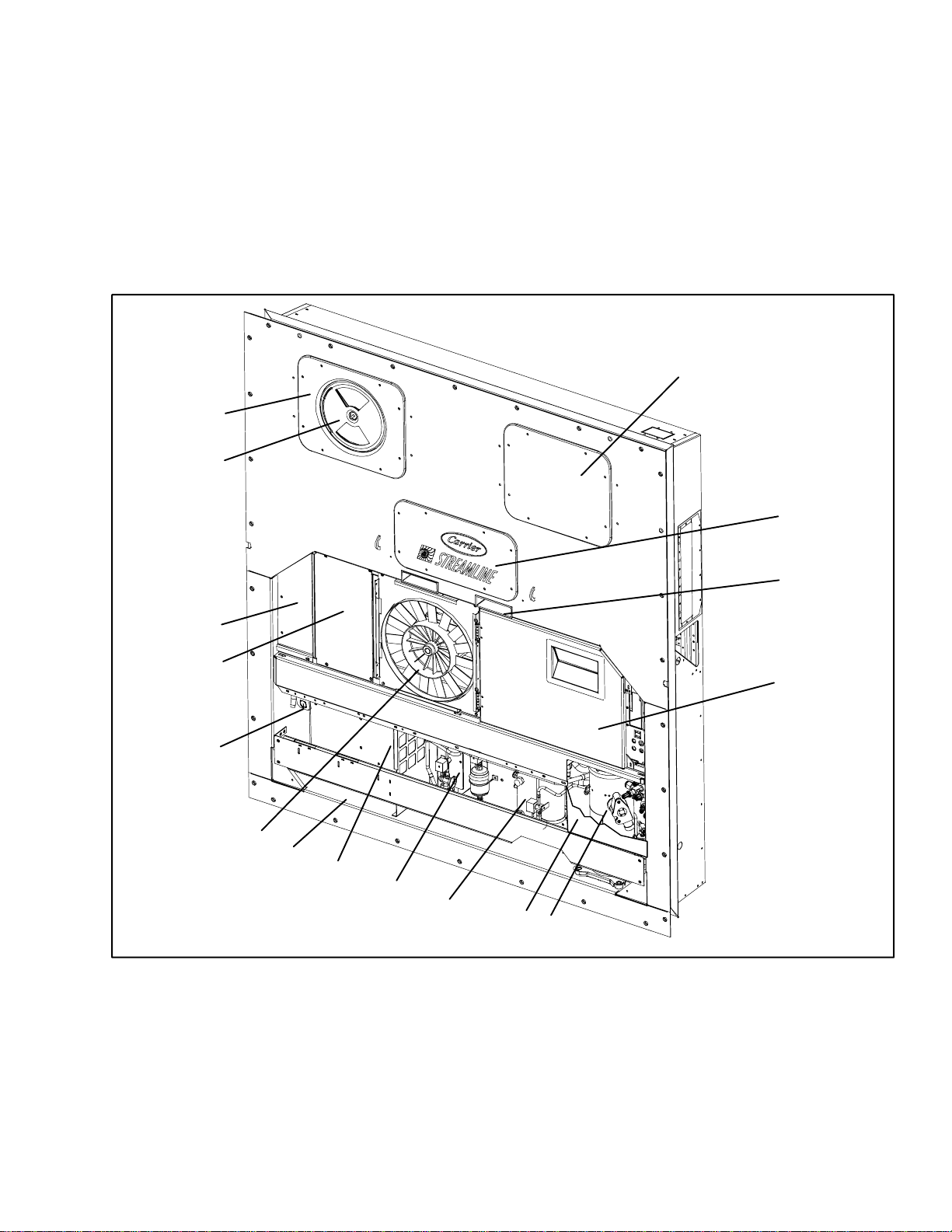
2.1.1 Refrigeration Unit -- Front Section
The unit is designed so that the majority of the
components are accessible from the front, see
Figure 2-1. Theupperaccesspanels allowentryintothe
evaporator section, and the center access panel allows
access to the evaporator expansion valve, unloader
15
14
valve, suction modulation valve and evaporator coil
heaters.Theunitmodelnumber,serialnumberandparts
identificationnumbercanbefoundon the serialplateto
the left of the economizer.
2.1.2 Fresh Air Makeup Vent
Thefunctionof the upperorlower makeup air vent isto
provide ventilation for commodities that require fresh
air circulation.
1
2
3
13
12
11
10
9
8
7
1. Access Panel (Evap. Fan #1)
2. Access Panel (Heaters, Suction Modulating
Valve, Unloader Valve & Evaporator
Expansion Valve)
3. Fork Lift Pockets
4. Control Box
5. Compressor
6. Receiver or Water Cooled Condenser
7. Economizer
8. Unit Serial Number, Model Number and
Figure 2-1 Refrigeration Unit -- Front Section
4
6
16
5
Parts Identification Number (PID) Plate
9. Power Cables and Plug
10. Condenser Fan
11. Interrogator Connector (Front left)
12. Blank Cover (Temperature Recorder Location)
13. Blank Cover (Lower Fresh Air Makeup Vent
Location)
14. Upper Fresh Air Makeup Vent
15. Access Panel (Evap. Fan #2)
16. Compressor Protection Panel (cutaway view)
2-1
T-309
Page 16
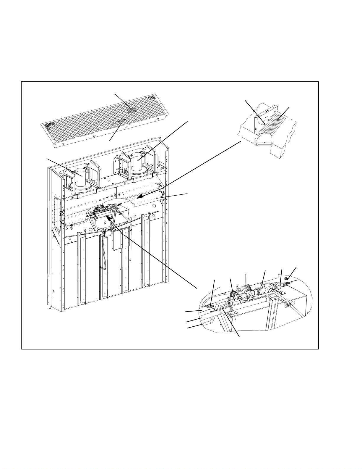
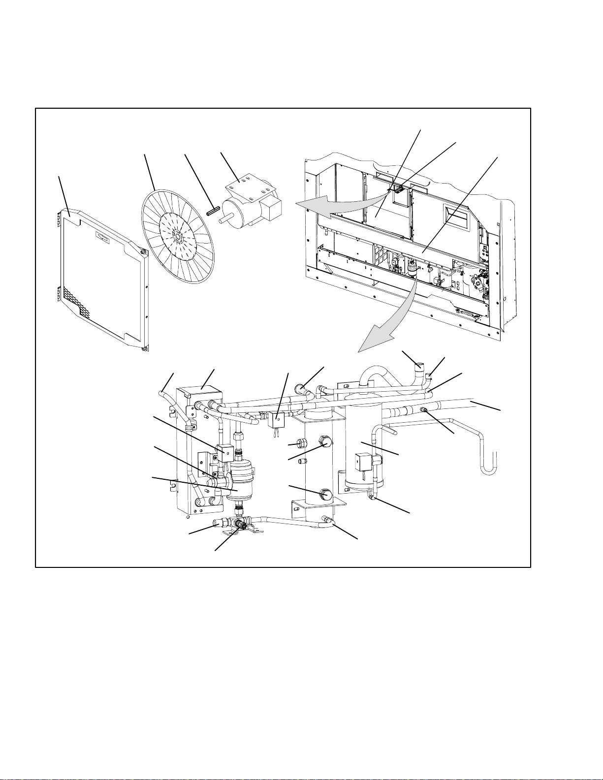
2.1.3 Evaporator Section
The evaporatorsection (Fi gure 2-2)contains the return
recorder sensor, return temperature sensor, evaporator
expansion valve, unloader valve, suction modulation
valve, dual-speed evaporator fans (EM1 and EM2),
evaporator coil and heater, defrost heaters, defrost
temperature sensor, heat termination thermostat and
suction temperature sensor.
The evaporator fans circulate air through the container
by pulling it in the top of the unit, directing it through
the evaporator coil, where it is heated or cooled, and
dischargingit at the bottom.
Theevaporatorcomponents are accessiblebyremoving
the upper rear panel (as shown in the illustration) or by
removing the front access panels.
3
4
2
1
8
9
10
5
17
11
12
7
6
1. Evaporator Fan Motor #1
2. Return Recorder/Temperature Sensor
3. Humidity Sensor
4. Evaporator Fan Motor #2
5. Defrost Temperature Sensor
6. Heater Termination Thermostat
7. Evaporator Coil
8. Evaporator Coil Heaters
9. Evaporator Expansion Valve Bulb
Figure 2-2 Evaporator Section
15
14
16
13
10. Evaporator Expansion Valve
11. Low Side Access Valve
12. Suction Modulating Valve
13. Suction Temperature Sensor
14. To Compressor
15. From Coil
16. To Coil
17. Unloader Solenoid Valve
2-2T -309
Page 17
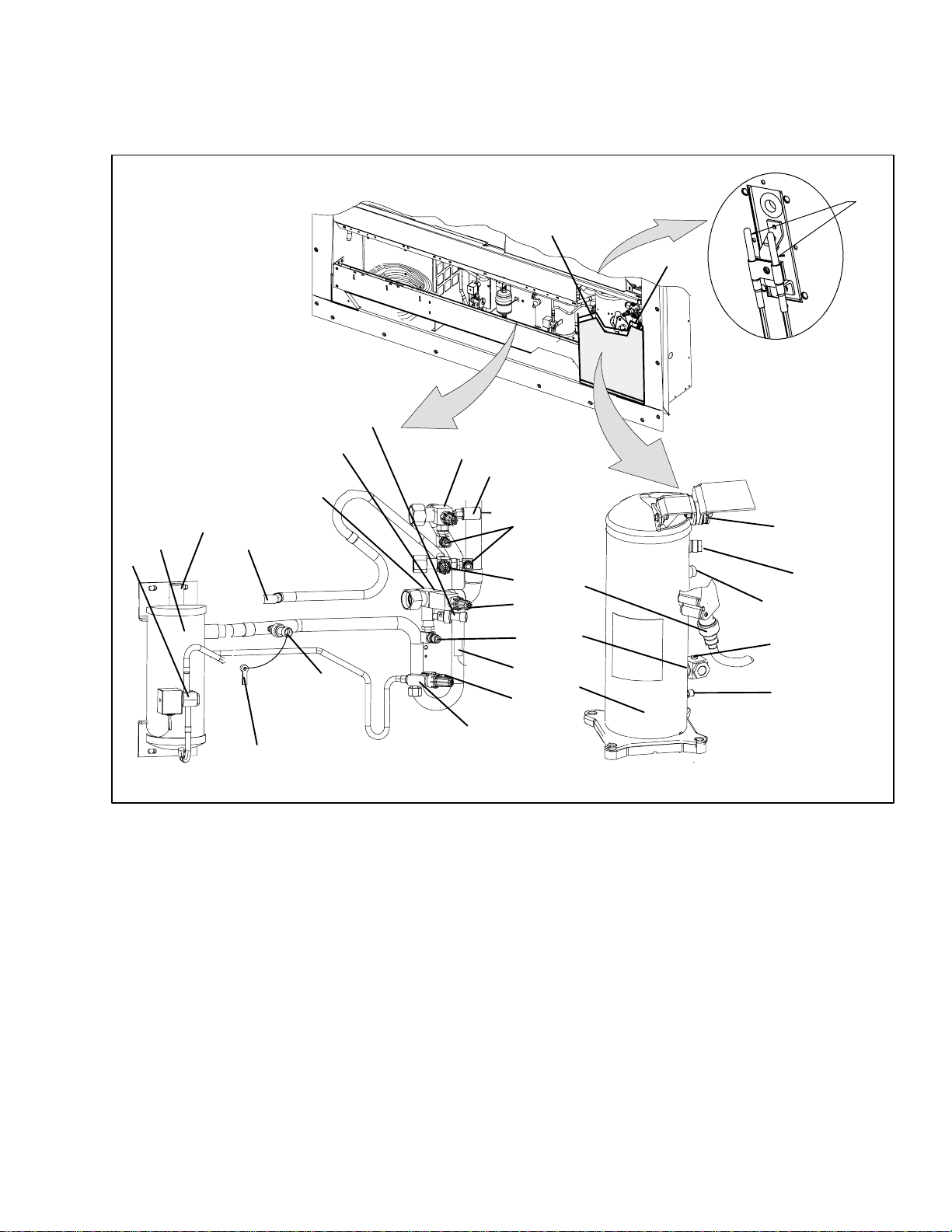
2.1.4 Compressor Section
The compressor section includes the compressor (with
high pressure switch) and the oil separator.
This section also contains the oil return solenoid,
compressor power plug, the discharge pressure
23
transducer, discharge temperature sensor and the
suction pressure transducers.
The supply temperature sensor, supply recordersensor
and ambient sensor are located at the left side of the
compressor.
2
1
4
22
21
20
18
19
17
16
3
1. Compressor Guard
2. Supply Temperature/Supply Recorder Sensor
Assembly
3. Ambient Sensor
4. Supply Air Thermometer Port (location)
5. Oil Drain
6. Compressor
7. Compressor Sight Glass
8 Compressor Power Plug
9. Discharge Service Valve
10. High Pressure Switch
11. Access Valve
Figure 2-3 Compressor Section
9
10
11
12
13
11
8
7
Discharge
Connection
(Hidden)
Economizer
Connection
Suction
Connection
Oil Return
Connection
14
11
6
5
15
12. Economizer Service Valve
13. Suction Service Valve
14. Discharge Temperature Sensor
15. Oil Return Service Valve
16. Discharge Pressure Transducer
17. Oil Return Solenoid Valve
18. Oil Separator
19. From Economizer
20. To Condenser
21. From Suction Modulating Valve
22. Suction Strainer
23. Suction Pressure Transducer
2-3
T-309
Page 18
2.1.5 Air Cooled Condenser Section
The air cooled condenser section (Figure 2-4) consists
of the condenser fan, condenser coil, receiver, sight
glass/moisture indicator, liquid line service valve,
filter-drier and fusible plug.
2
1
3
4
Thecondenserfanpullsair in thebottom ofthe coiland
it is discharged horizontally out through the condenser
fan grille.
This section also contains the economizer,economizer
solenoid valve, economizer expansion valve and the
liquid injection solenoid valve.
5
6
7
9
27
26
25
24
1. Grille and Venturi Assembly
2. Condenser Fan
3. Key
4. Condenser Fan Motor
5. Condenser Coil
6. Condenser Motor Mounting Bracket
7. Condenser Coil Cover
8. Economizer
9. To Evaporator Expansion Valve
10. Liquid Injection Solenoid Valve
11. From Condenser
12. To Condenser
13. To Compressor Economizer Connection
14. To Unloader Solenoid Valve
8
23
Figure 2-4 Condenser Section
12
10
22
21
20
14
17
19
15. From Compressor Discharge
16. Discharge Pressure Transducer
17. Oil Separator
18. To Oil Return Solenoid
19. Receiver
20. Sight Glass/Moisture Indicator
21. Sight Glass
22. Fusible Plug
23. Access Valve
24. Liquid Line Service Valve
25. Filter-Drier
26. Economizer Expansion Valve
27. Economizer Solenoid Valve
11
13
15
16
18
2-4T -309
Page 19
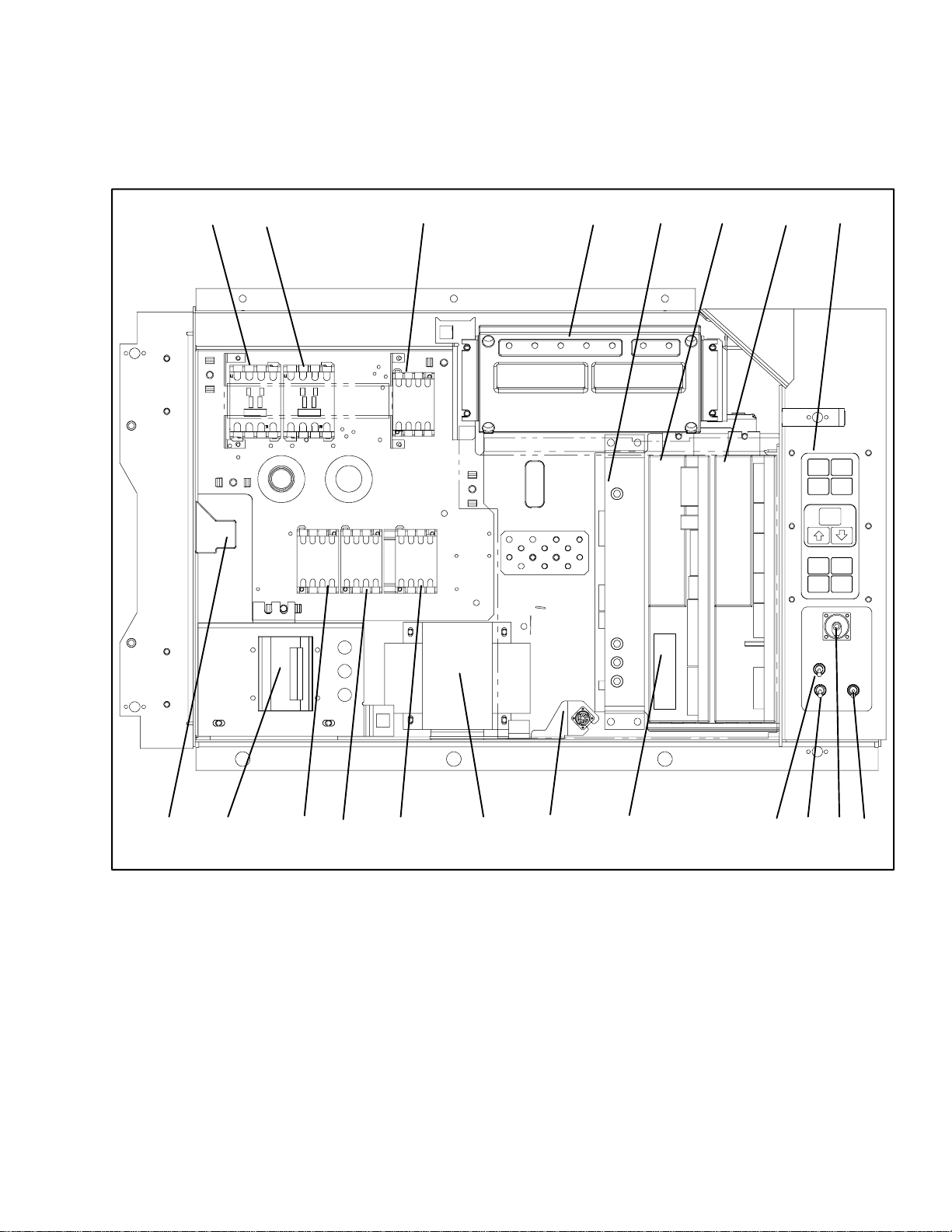
2.1.6 Control Box Section
The control box (Figure 2-5) includes the manual
operationswitches;circuitbreaker(CB-1);compressor,
fan and heater contactors; control power transformer;
fuses;key pad;display module; currentsensormodule;
controller module expansion module and the
communications interface module.
2.1.7 Communications Interface Module
The communications interface module is a slave
module which allow communication with a master
centralmonitoring station. The module will respond to
communication and return information over the main
powerline.Referto themastersystemtechnicalmanual
for further information.
12 3 4 5 6 7
8
1920 151718
1. Compressor Phase A Contactor
2. Compressor Phase B Contactor
3. Heater Contactor
4. Display Module
5. Communications Interface Module
6. Controller/DataCORDER Module (Controller)
7. Expansion Module
8. Key Pad
9. Start-Stop Switch
10. Remote Monitoring Receptacle
Figure 2-5 Control Box Section
14
1 1. Manual Defrost Switch
12. Condenser Fan Switch
13. Controller Battery Pack
14. Interrogator Connector (Box Location)
15. Control Transformer
16. Evaporator Fan Contactor - High
17. Evaporator Fan Contactor - Low
18. Condenser Fan Contactor
19. Circuit Breaker -- 460V
20. Current Sensor Module
2-5
121316
10 911
T-309
Page 20

2.2 REFRIGERATION SYSTEM DATA
a.Compressor/Moto
r
y
d.H
T
h
H
igh
P
h
ibleP
l
i.R
D
i
k.W
h
Assembly
b. Evaporator Expansion
Valve Superheat
c. Economizer Expansion
Valve Superheat
eaterTermination
e.
f. Refrigerant Charge
g.Fus
h. Sight Glass/Moisture Indicator
j. Unit Weight
ressureSwitc
ug
upture
aterPressureSwitc
sc
ermostat
Model RSH105
Weight (Dry) 46.5 kg (103 lb)
Approved Oil Mobil ST32
Oil Charge 2957 ml (100 ounces)
The oil level range, with the compressor off,
Oil Sight Glass
should be between the bottom and one-eighth
level of the sight glass.
Verify at --18 _C
(0 _F) container box
4.4to6.7_C(8to12_F)
temperature
4.4 to 11.1 _C(8to20_F)
Opens 54 (¦ 3) _C = 130 (¦ 5) _F
Closes 38 (¦ 4) _C = 100 (¦ 7) _F
Cutout 25 (¦ 1.0) kg/cm@ = 350 (¦ 10) psig
Cut-In 18 (¦ 0.7) kg/cm@ = 250 (¦ 10) psig
Unit Configuration Charge Requirements -- R-134a
4--RowCoil
Water-Cooled
Condenser
Receiver
5.33 kg
(11.75 lbs)
4.99kg
(11.0 lbs)
Melting point 99 _C = (210 _F)
Torque 6.2 to 6.9 mkg (45 to 50 ft-lbs)
Torque 8.9 to 9.7 mkg (65 to 70 ft-lbs)
Bursts at 35 ¦ 5% kg/cm@ = (500 ¦ 5% psig)
Torque 6.2 to 6.9 mkg (45 to 50 ft-lbs)
Refer t o unit model number plate.
Cut-In 0.5 ¦ 0.2 kg/cm@ (7 ¦ 3psig)
Cutout 1.6 ¦ 0.4 kg/cm@ (22 ¦ 5psig)
2-6T -309
Page 21
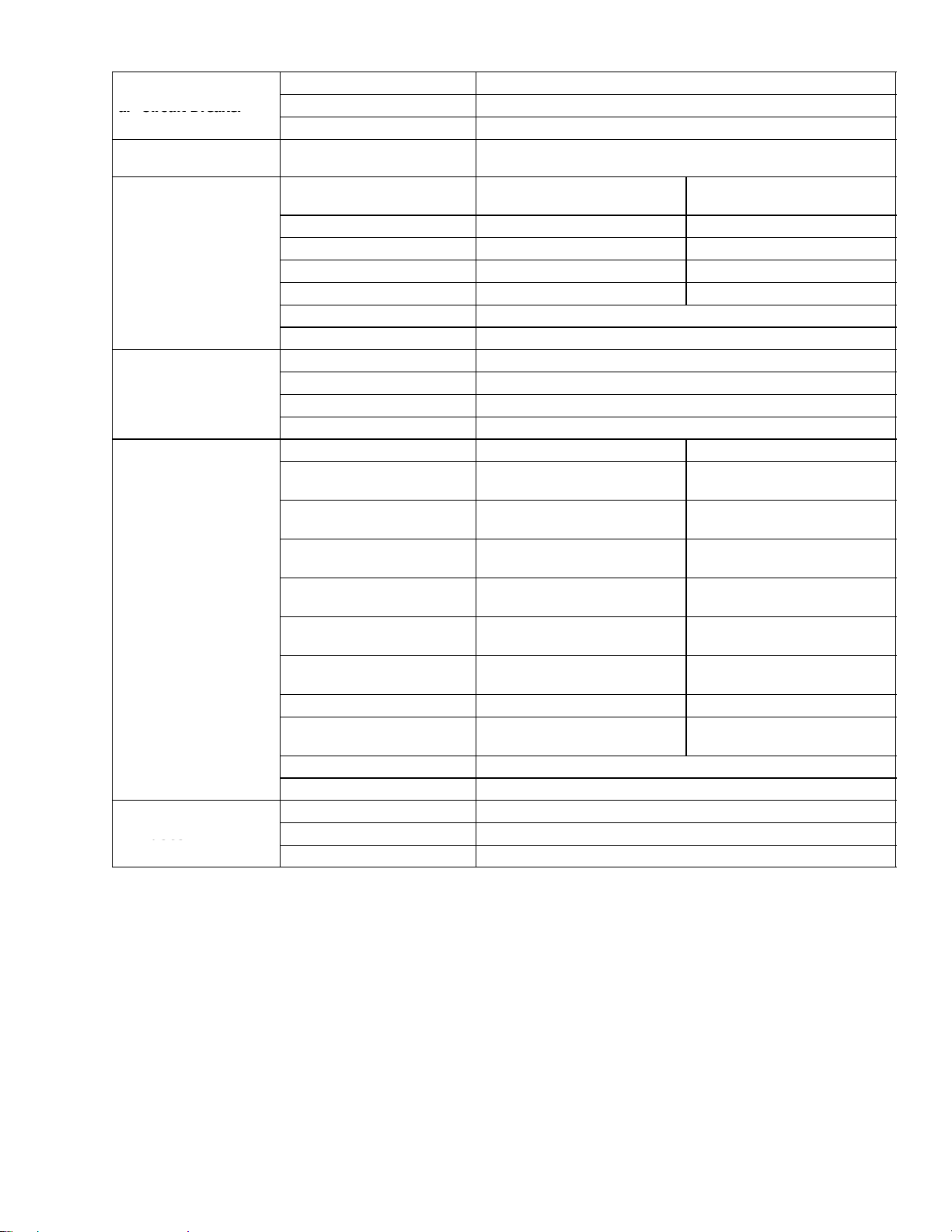
2.3 ELECTRICAL DAT A
a.CircuitBreake
r
c.CondenserFa
n
d.EvaporatorCoi
l
e.EvaporatorFan
f.Fuses
a. Circuit Breaker
b. Compressor
Motor
Motor
d. Evaporator Coil
Heaters
Motor(s)
f. Fuses
CB-1 Trips at 29 amps
CB-2 (50 amp) Trips at 62.5 amps
CB-2 (70 amp) Trips at 87.5 amps
Full Load Amps (FLA) 13 amps @ 460 vac
380 vac, Single Phase,
50 hz
Full Load Amps 1.3 amps 1.6 amps
Horsepower 0.43 hp 0.75 hp
Rotations Per Minute 1425 rpm 1725 rpm
Voltage and Frequency 360 -- 460 vac ¦ 2.5 hz 400 -- 500 vac ¦ 2.5 hz
Bearing Lubrication Factory lubricated, additional grease not required.
Rotation Counter-clockwise when viewed from shaft end.
Number of Heaters 4
Rating 750 watts +5/--10% each @ 230 vac
Resistance (cold) 66.8 to 77.2 ohms @ 20 _C(68_F)
Type Sheath
380 vac/50 hz 460 vac/60 hz
Full Load Amps
High Speed
Full Load Amps
Low Speed
Nominal Horsepower
High Speed
Nominal Horsepower
Low Speed
Rotations Per Minute
High Speed
Rotations Per Minute
Low Speed
Voltage and Frequency 360 -- 460 vac ± 1.25 hz 400 -- 500 vac ± 1.5 hz
Voltage & Frequency us-
ing power autotransformer
Bearing Lubrication Factory lubricated, additional grease not required
Rotation CW when viewed from shaft end
Control Circuit 10 amps (F3)
Controller/DataCORDER 5amps(F1&F2)
Expansion Module 10 amps (F4)
180 -- 230 vac ± 1.25hz 200 -- 250 vac ± 1.5 hz
1.6 2.0
0.8 1.0
0.70 0.84
0.09 0.11
2850 rpm 3450 rpm
1425 rpm 1750 rpm
460 vac, Single Phase,
60 hz
2-7
T-309
Page 22

PARAGRAPH 2.3 -- Continued
idityS
Orange wire Power
Red wire Output
Brown wire Ground
Input voltage 5vdc
g.Hum
ensor
Output voltage 0to3.3vdc
30% 0.99 V
50% 1.65 V
70% 2.31 V
90% 2.97 V
Output voltage readings verses relative humidity (RH) percentage:
2.4 SAFETY AND PROTECTIVE DEVICES
Unit components are protected from damage by safety
and protective devices listed in t he following table.
Thesedevicesmonitortheunitoperatingconditionsand
open a set of electrical contacts when an unsafe
condition occurs.
Open safetyswitch contacts oneitherorbothofdevices
Table 2-1 Safety and Protective Devices
UNSAFE CONDITION
IP-CP or HPS will shut down the compressor.
Opensafetyswitch contacts ondeviceIP-CM will shut
down the condenser fan motor.
Theentirerefrigerationunit willshutdown ifoneofthe
following safety devices open: (a) Circuit Breaker(s);
(b)Fuse(F3/15A);or(c)EvaporatorFanMotorInternal
Protector(s) -- (IP-EM).
DEVICE DEVICE SETTING
Circuit Breaker (CB-1) -- Manual Reset Tripsat 29 amps (460 vac)
Excessive current draw Circuit Breaker (CB-2, 50 amp) --Manual Reset Tripsat 62.5 amps (230 vac)
Circuit Breaker (CB-2, 70 amp) --Manual Reset Trips at 87.5 amps (230 vac)
Excessive current draw in the
control circuit
Excessive current draw by the
controller
Excessive current draw by the
expansion module
Excessive condenser fan motor winding temperature
Fuse (F3) 10 amp rating
Fuse (F1 & F2) 5 amp rating
Fuse (F4) 10 amp rating
Internal Protector (IP-CM) -- Automatic Reset N/A
Excessive compressor motor
winding temperature
Excessive evaporator fan motor(s) winding temperature
Abnormal pressures/temperatures in the high refrigerant
side
Abnormally high discharge
pressure
Internal Protector (IP-CP) -- Automatic Reset N/A
Internal Protector(s) (IP-EM) -- Automatic Reset N/A
Fusible Plug -- Used on the Receiver
Rupture Disc -- Used on the Water-Cooled Con-
93 _C = (200 _F)
35 kg/cm@ = (500 psig)
denser
High Pressure Switch (HPS)
2-8T -309
Opens at 25 kg/cm@
(350 psig)
Page 23

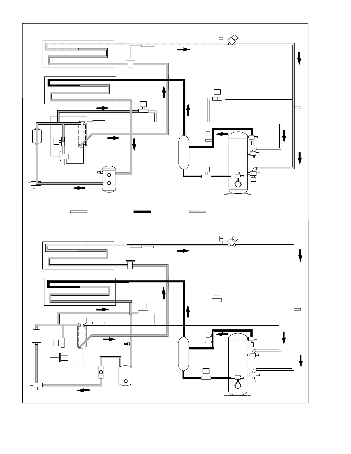
2.5 REFRIGERATION CIRCUIT
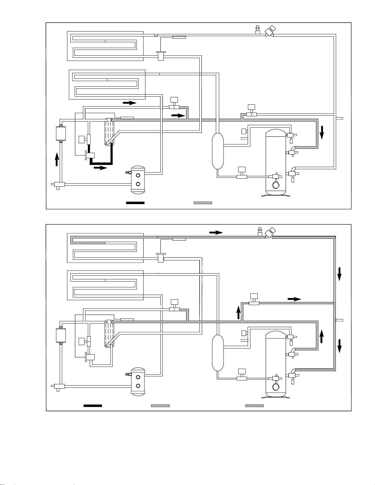
2.5.1 Standard Operation
Starting at the compressor, (see Figure 2-6, upper
schematic) the suction gas is compressed to a higher
pressure and temperature.
Inthestandardmode,boththeeconomizerandunloader
solenoid valves are closed. The gas flows through the
discharge service valve into the oil separator. In the
separator,oil is removed from the refrigerantand stored
forreturntothecompressorwhentheoil returnsolenoid
valveisopenedbythecontroller.Theoilreturnsolenoid
valveisanormallyopenvalvewhichallowsreturnofoil
during the off cycle.
The refrigerant gas continues into the air-cooled
condenser. When operating with the air-cooled
condenser active, air flowing across the coil fins and
tubes cools the gas to saturation temperature. By
removing latent heat, the gas condenses to a high
pressure/high temperature liquid and flows to the
receiver which stores the additional charge necessary
for low temperature operation.
Whenoperatingwiththewatercooledcondenseractive
(see Figure 2-6, lower schematic), the refrigerant gas
passes through the air cooled condenser and enters the
watercooled condenser shell. The waterflowinginside
thetubing coolsthe gasto saturationtemperatureinthe
same manner as the air passing over the air cooled
condenser. The refrigerant condenses on the outside of
the tubes and exits as a high temperature liquid. The
water cooled condenser also acts as a receiver, storing
excess refrigerant.
The liquid refrigerantcontinues through the liquid line
service valve, the filter-drier (which keeps refrigerant
clean and dry) and the economizer (which is not active
during standardoperation) to the evaporator expansion
valve. As the liquid refrigerant passes through the
variable orifice of the expansion valve, some of it
vaporizes into a gas (flash gas). Heat is absorbed from
the return air by the balance of the liquid, causing it to
vaporize in the evaporator coil. The vapor then flows
through the suction modulation valve to the
compressor.
Theevaporatorexpansionvalveisactivatedbythebulb
strapped to the suction line near the evaporator outlet.
The valve maintains a constant superheat at the coil
outlet regardless of load conditions.
On systems fitted with a water pressure switch, the
condenser fan will be off when there is sufficient
pressure to open the switch. If water pressure drops
belowthe switch cut out setting, thecondenser fanwill
be automatically started. When operating a system
fitted with a condenser fan switch, the condenser fan
willbeoffwhentheswitch isplaced in the“O”position.
The condenser fan will be on when theswitch is placed
in the “I” position.
2.5.2 Economized Operation
Intheeconomizedmodethefrozenrangeandpulldown
capacityoftheunitisincreasedbysubcoolingtheliquid
refrigerant entering the evaporator expansion valve.
Overall efficiency is increased because the gas leaving
the economizer enters the compressor at a higher
pressure, therefore requiring less energy to compress it
to the required condensing conditions.
During economized operation, flow of refrigerant
through the main refrigerant system is identical to the
standard mode. (The unloader solenoid valve is
de--energized [closed] by the controller.)
Liquid refrigerant for use in the economizer circuit is
taken from the main liquid line as it leaves the
filter--drier(seeFigure 2-7).Theflowis activatedwhen
thecontroller energizesthe economizer solenoid valve.
The liquid refrigerant flows through the economizer
expansion valve and the economizer internal passages
absorbingheatfromtheliquid refrigerantflowingtothe
evaporator expansion valve. The resultant “medium”
temperature/pressure gas enters the compressor at the
economizer service valve.
2.5.3 Unloaded Operation
The system will operate in the unloaded mode during
periods of low load, during periods of required
discharge pressure or current limiting, and during
start--up.
During unloaded operation, flow of refrigerantthrough
the main refrigerant system is identical to the standard
mode. (The economizersolenoid valve isde--energized
[closed] by the controller.)
In the unloaded mode, a portion of the mid--stage
compressed gas is bypassed to decrease compressor
capacity. The flow is activated when the controller
opens the unloader solenoid valve (see Figure 2-7.
Opening of the valve creates a bypass from the
economizerservicevalvethroughtheunloadersolenoid
valve and into the suction line on the outlet side of the
suction pressure modulation valve.
Asloadonthesystemdecreases,thesuctionmodulating
valve decreases flow of refrigerant to the compressor.
This action balances the compressor capacity with the
loadandpreventsoperation with low coiltemperatures.
In this mode of operation, the liquid injection solenoid
valve will open as required to provide sufficientliquid
refrigerant flow into the suction line for cooling of the
compressor motor.
2-9
T-309
Page 24
EVAPORATOR
STANDARD OPERATION WITH RECEIVER
LOW SIDE ACCESS VALVE
FILTER
DRIER
ECONOMIZER
TXV
LIQUID LINE
SERVICE
CONNECTION
CONDENSER
ESV
FUSIBLE PLUG
TXV BULB
TXV
USV
LIV
ECONOMIZER TXV BULB
ECONOMIZER
OIL SEPARATOR
RECEIVER
SIGHTGLASS
MOISTURE INDICATOR
DISCHARGE LIQUID SUCTION
DPT
CPDS
ORV
OIL RETURN
SERVICE VALVE
SMV
COMPRESSOR
DISCHARGE
SERVICE
CONNECTION
HPS
ECONOMIZER
SERVICE
CONNECTION
SUCTIONSERVICE
CONNECTION
SPT
STS
FILTER
DRIER
STANDARD OPERATION WITH WATER COOLED CONDENSER
ECONOMIZER
TXV
LIQUID LINE
SERVICE
CONNECTION
EVAPORATOR
CONDENSER
ECONOMIZER TXV BULB
ECONOMIZER
ESV
SIGHTGLASS/
MOISTURE INDICATOR
TXV
RUPTURE DISC
WATER COOLED
CONDENSER
TXV BULB
LIV
LOW SIDE ACCESS VALVE
USV
DPT
CPDS
ORV
OIL RETURN
SERVICE VALVE
SMV
COMPRESSOR
DISCHARGE
SERVICE
CONNECTION
HPS
SPT
QUENCH
TXV
BULB
ECONOMIZER
SERVICE
CONNECTION
SUCTIONSERVICE
CONNECTION
CPSS
Figure 2-6 Refrigeration Circuit Schematic -- Standard Operation
2-10T-309
Page 25
EVAPORATOR
LOW SIDE ACCESS VALVE
CONDENSER
ESV
ECONOMIZER
TXV
LIQUID LINE
SERVICE CONNECTION
ECONOMIZER TXV BULB
ECONOMIZER
RECEIVER
LIQUID ECONOMIZER PRESSURE
TXV BULB
TXV
LIV
OIL SEPARATOR
SMV
ECONOMIZER
SERVICE
CONNECTION
Figure 2-7 Refrigeration Circuit Schematic -- Economized Operation
TXV BULB
TXV
LIV
ECONOMIZER TXV BULB
OIL SEPARATOR
RECEIVER
SMV
USV
SUCTIONSERVICE
CONNECTION
LIQUID ECONOMIZER PRESSURE
SUCTION
Figure 2-8 Refrigeration Circuit Schematic -- Unloaded Operation
2-11
T-309
Page 26
SECTION 3
MICROPROCESSOR
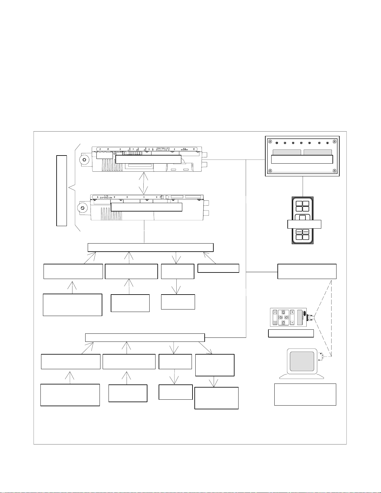
3.1 TEMPERATURE CONTROL MICROPROCESSOR SYSTEM
The temperature control Micro-Link 2i microprocessor
system (see Figure 3- 1) consists of a key pad, display
module, the control module & expansion module set
(controller)and interconnecting wiring. The controller
houses the temperature control software and the
DataCORDER Software. The temperature control
software functions to operate the unit components as
required to provide the desired cargo temperature and
humidity. The DataCORDER software functions to
record unitoperatingparameters and cargo temperature
parameters for future retrieval. Coverage of the
temperaturecontrolsoftwarebeginswithparagraph3.2.
Coverageof theDataCORDER software is providedin
paragraph 3.6.
The key pad and display module serve to provide user
accessand readoutsfor bothofthe controller functions,
temperaturecontrol and DataCORDER. The functions
are accessed by key pad selections and viewed on the
displaymodule.Thecomponentsaredesignedtopermit
ease of installation and removal.
C
O
N
T
R
O
L
L
E
R
TEMPERATURE CONTROL SOFTWARE
CONFIGURATION
SOFTWARE
CONFIGURATION
VARIABLE
(CnF##)
CONTROL MODULE DISPLAY MODULE
EXPANSION MODULE
KEY PAD
OPERATIONAL
SOFTWARE
FUNCTION
CODE (Cd)
DataCORDER SOFTWARE
ALARMS
(AL<70)
TO
DISPLAY
PRE--TRIP INTERROGATION
CONNECTOR
DATAREADER
CONFIGURATION
SOFTWARE
CONFIGURATION
VARIABLE
(dCF## read only)
OPERATIONAL
SOFTWARE
FUNCTION
CODE (dC)
Figure 3- 1 Temperature Control System
ALARMS
(AL>69)
TO
DISPLAY
STORAGE
MEMORY
(Scrollback)
3-1
DATA
TO
DISPLAY
Computer Device
With DataLine
Software
T-309
Page 27
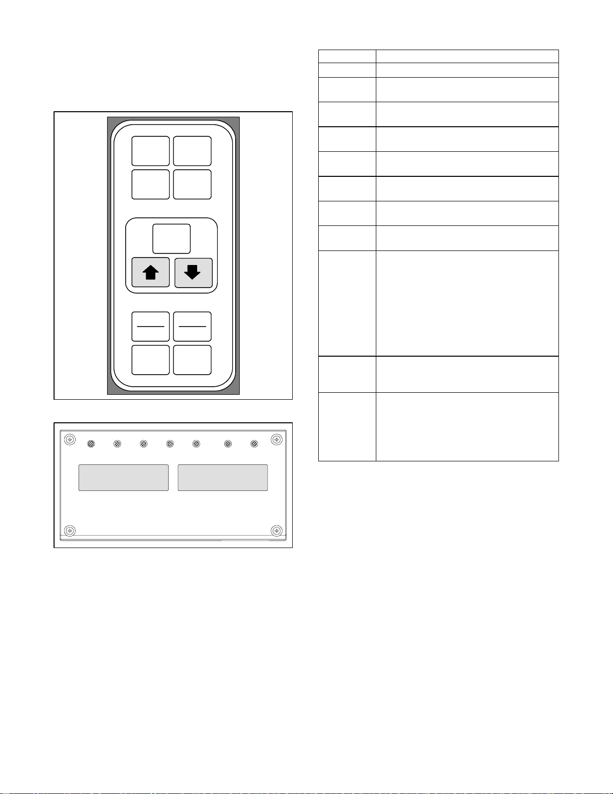
3.1.1 Key Pad
Thekey pad (Figure 3- 2)is mounted on the right-hand
side of the control box. The key pad consists of eleven
pushbuttonswitchesthatactas the user’sinterfacewith
the controller. Descriptions of the switch functions are
provided in Table 3-1.
CODE
SELECT
ALARM
LIST
RETURN
SUPPLY
BATTERY
POWER
Figure 3- 2 Key Pad
COOL HEAT DEFROST IN RANGEALARM SUPPLY RETURN
PRE
TRIP
DEFROST
INTERVAL
ENTER
_C
_F
ALT.
MODE
Table 3-1 Key Pad Function
KEY FUNCTION
Code Select Accesses function codes.
Pre-Trip
Alarm List
Defrost
Interval
Enter
Arrow Up
Arrow
Down
Return/
Supply
Displaysthe pre-trip selection menu. Discontinues pre-trip in progress.
Displaysalarm list and clears the alarm
queue.
Displaysselected defrost interval.
Confirmsa selection or saves a selection
to the controller.
Change or scroll a selection upward Pre-
trip advance or test interruption.
Change or scroll a selection downward.
Pre-trip repeat backward.
Displays non-controlling probe tempera-
ture (momentary display).
Displaysalternate English/Metricscale
(momentary display). When set to _F,
pressure is displayed in psig and vacuum
in “/hg. “P” appears after the value to in-
_C/_F
dicate psig and “i” appears for inches of
mercury.
When set to _C. pressure readings are in
bars. “b” appears after the value to indicate bars.
Battery
Power
Initiate battery backup mode to allow set
point and function code selection if AC
power is not connected.
This key is pressed to switch the functions
from the temperature software to the Da-
ALT Mode
taCORDERSoftware. The remaining keys
function the same as described above except the readings or changes are made to
the DataCORDER programming..
SETPOINT/Code AIR TEMPERATURE/Data
Figure 3- 3 Display Module
3.1.2 Display Module
The display module (Figure 3- 3) consists of two
backlightedfivedigit LCD displaysandsevenindicator
lights. The i ndicator lights include:
1. Cool -- White LED: Energized when the refrigerant
compressor is energized.
2. Heat-- OrangeLED:Energized toindicateheaterop-
eration in the heat or defrost mode.
3. Defrost-- OrangeLED: Energizedwhentheunit isin
the defrost mode.
4. In-Range -- Green LED: Energized whe n the con-
trolled temperature probe is within specified tolerance of set point.
NOTE
The controlling probe in the perishable range
will be the SUPPLY air probe and the controlling probe in the frozen range will be the
RETURN air probe.
5. Supply--YellowLED:Energizedwhenthesupplyair
probe is used for control. When this LED is illuminated,the temperaturedisplayed in the AIR TEMPERATURE display is the reading at the supply air probe.
ThisLED will flash if dehumidificationor humidification is enabled.
6. Return -- YellowLED:Energizedwhenthereturnair
probe is used for control. When this LED is illuminated, the temperature displayed in the AIR TEMPERA TUREdisplayis thereading atthe returnairprobe. This LED will flash if dehumidification or
humidification is enabled.
7. Alarm-- Red LED: Energizedwhenthereis anactive
or an inactive shutdown alarm in the alarm queue
3-2T -309
Page 28
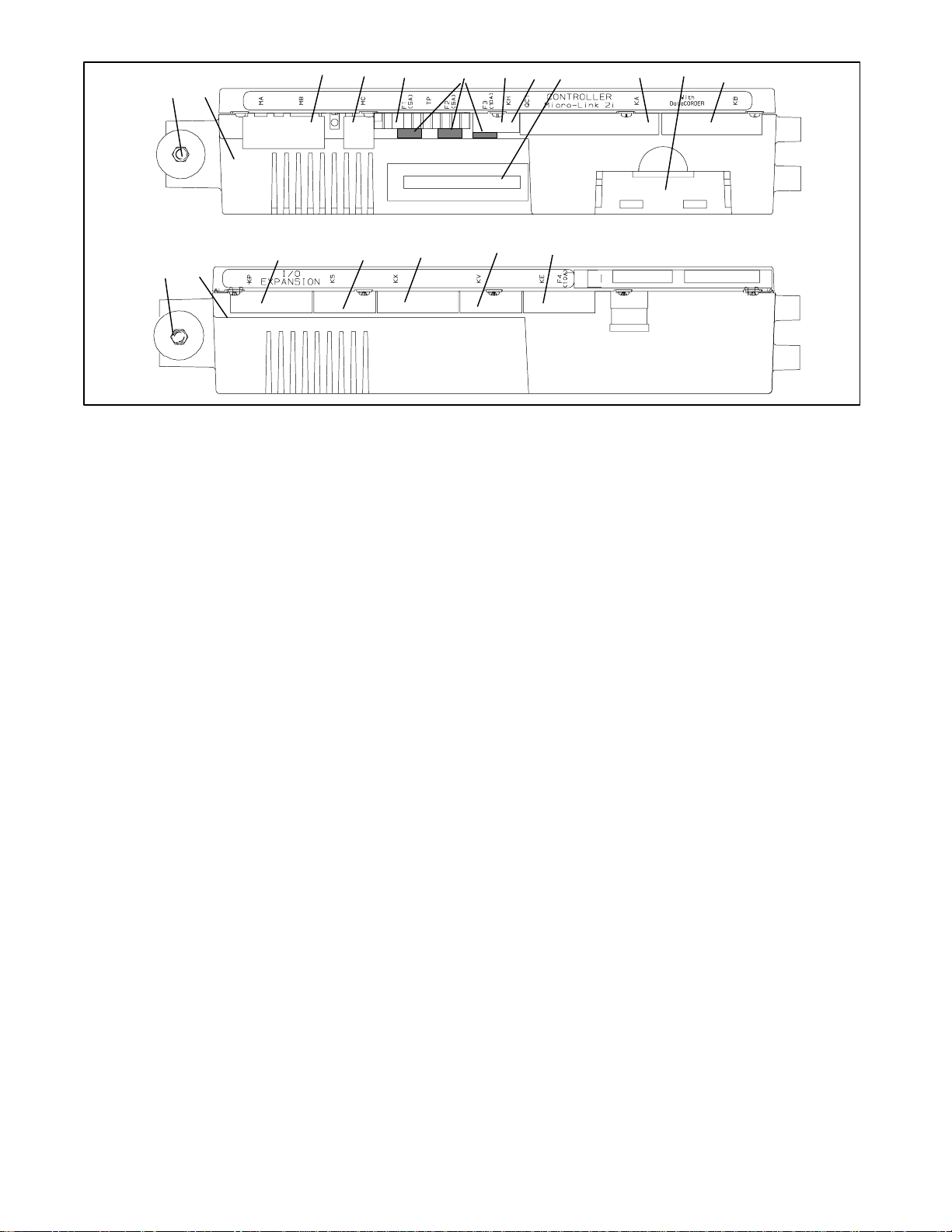
12
33 3 3 345 67
8
9
1
1. Mounting Screw
2. Micro-Link 2i Control/DataCORDER Module
3. Connectors
4. Test Points
5. Fuses
3.1.3 Controller
3
Figure 3- 4 Control and Expansion Modules
3
3 3 3
CAUTION
Do not remove wire harnesses from controller modules unless you are grounded to the
unit frame with a static safe wrist strap.
CAUTION
Unplug all controller module wire harness
connectors before performing arc welding
on any part of the container.
NOTE
Do not attempt to service the controller modules. Breaking the seal will void the warranty.
The Micro--Link 2i controller is a dual module
microprocessoras shown inFigure 3- 4. Itis fittedwith
test points, harness connectors and a software card
programming port.
3.2 CONTROLLER SOFTWARE
The controller software is a custom designed program
that is subdivided into the Configuration Software and
the Operational Software. The controller software
performs the following functions:
a. Control supply or return air temperature to required
limits, provide modulated refrigeration operation,
economized operation, unloaded operation, electric
heatcontrolanddefrost. Defrost isperformedtoclear
build up of frost and ice and ensure proper air flow
across the coil.
b. Providedefaultindependentreadoutsofsetpointand
supply or return air temperatures.
6. Control Circuit Power Connection
(Location: In back of controller)
7. Software Programming Port
8. Battery Pack
9. Expansion Module
c. Provide abilityto readand (ifapplicable)modifythe
Configuration Software Variables, Operating Software Function Codes and Alarm Code Indications.
d. ProvideaPre-Tripstep-by-stepcheckoutofrefrigera-
tion unit performance including: proper component
operation,electronicand refrigerationcontroloperation, heater operation, probe calibration, pressure
limiting and current limiting settings.
e. Provide battery powered ability to access or change
selected codes and set point without AC power connected
f. Providetheabilitytoreprogramthe softwarethrough
theuseofamemorycard. Thememorycardautomaticallydownloadsnewsoftwaretothecontrollerwhen
inserted.
3.2.1 Configuration Software (Configuration Variables)
The Configuration Software is a variable listing of the
components available for use by the Operational
Software. This software is factory installed in
accordance withthe equipmentfitted and options listed
on the original purchase order. Changes to the
Configuration Software are required only when a new
controller hase been installed or a physical change has
beenmadetothe unit suchasthe additionor removalof
an option. A Configuration Variable list is provided in
Table 3-4. Change to the factory installed
ConfigurationSoftwareis achievedvia a configuration
card or communications.
3-3
T-309
Page 29

3.2.2 Operational Software (Function codes)
The Operational Software is the actual operation
programming of the controller which activates or
deactivates components inaccordancewith currentunit
operating conditions and operator selected modes of
operation.
TheprogrammingisdividedintofunctionCodes.Some
of the codes are read only while the remaining codes
may be user configured. The value of the user
configurable codes can be assigned in accordance with
user desired mode of operation. A list of the function
codes is provided in Table3-5.
Toaccess the function codes, perform the following:
a. Press the CODE SELECT key, then press an arrow
key until the left window displays the desired code
number.
b. The right window will display the value of this item
for five seconds before returning to the normal display mode.
c. If a longer time is desired, press the ENTER key to
extend the time to 30 seconds.
3.3 MODES OF OPERATION
The Operational Software responds to various inputs.
These inputs come from the temperature and pressure
sensors,thetemperaturesetpoint,the settings of thethe
configuration variables and the function code
assignments. The action t aken by the Operational
Software will change if any one of the inputs changes.
Overall interaction of the inputs is described as a
“mode” of operation. The modes of operation include,
perishable (chill) mode and frozen mode. Descriptions
ofthe controllerinteractionand modesof operationare
provided in the following sub paragraphs.
3.3.1 Temperature Control -- Perishable Mode
With configuration variable CnF26 (Heat Lockout
Temperature) set to --10_C the perishable mode of
operation i s active with set points at or above --10_C
(+14_F). With the variable set to --5_C, the perishable
mode is active at or above --5_C(+23_F). Refer to
Table 3-4.
When in the perishable mode the controller maintains
the supply air temperature at set point, the SUPPLY
indicatorlightwillbeilluminatedonthedisplaymodule
and the default reading on the display window will be
the supply temperature sensor reading.
When the supply air temperature enters the in-range
temperature tolerance (as selected at function code
Cd30), the in-range light will energize.
3.3.2 Defrost Interval
Function code Cd27 may be operator set to initiate
defrostatintervalsof3, 6,9, 12or24hours. It mayalso
be set to OFF (no defrost). The factory default is 12
hours. (Refer to Table 3-5).
3.3.3 Failure Action
Function code Cd29 may be operator set to allow
continuedoperation in the event the control sensors are
readingout of range. The factory default is full system
shutdown. (Refer to Table 3-5).
3.3.4 Generator Protection
Function codes Cd31(Stagger Start, Offset Time) and
Cd32 (Current Limit) may be operator set to control
startupsequenceofmultipleunitsandoperatingcurrent
draw.Thefactorydefaultallowsondemandstarting(no
delay) of units and normal current draw. Refer to
Table 3-5.
3.3.5 Compressor High Temperature, Low Pressure Protection.
The controller monitors compressor suction and
discharge temperatures and pressures. If the discharge
temperature exceedsa certain limit, the liquidinjection
valve is opened to provide sufficient liquid refrigerant
flow into the economizer line to reduce the discharge
temperature. If the liquid injection is unable to reduce
the discharge temperature sufficiently and the
temperature exceeds the allowed limit, the compressor
willcycle off on a 3 minute timer. The compressorwill
alsocycleoffinasimilarmannerifthe suction pressure
fallsbelowtheallowedlimit.Condenserandevaporator
fans continue to operate during t he compressor off
cycle.
3.3.6 Perishable Mode -- Conventional
The unit is capable of maintaining supply air
temperaturet o within ¦0.25_C(¦0.5_F)of set point.
Supply air temperature is controlled by positioning of
the suction modulation valve (SMV), cycling of the
compressor and cycling of the heaters.
When cooling from a temperature that is more than
2.5_C (4.5_F)abovesetpoint, t he systemwill bein the
perishable pull down mode. It will be in economized
operation with a target S MV position of 100% open.
However, pressure and current limit functions may
restrict the valve, if either exceeds the preset value.
Once set point is reached, the unit will transition to the
perishable steady state mode. This results in unloaded
operationwith some restriction of the SMV. The SMV
will continue to close and restrict refrigerant flow until
the capacity of the unit and the load are balanced.
If the SMV is at minimum modulation, the controller
has determined that cooling is not required, or the
controllerlogicdeterminessuctionpressureisatthelow
pressure limit, the unit will transition to the perishable
idle mode. The compressor is turned off and the
evaporator fans continue to run to circulate air
throughout the container.If temperaturerises above set
point +0.2_C, the unit will transition back to the
perishable steady state mode
If the temperature drops to 0.5_C (0.9_F) below set
point, t he unit will transition to the perishable heating
3-4T -309
Page 30

mode and the heaters will be energized . The unit will
transition back to the perishable idle mode when the
temperaturerises to 0.2_C (0.4_F) below the set point
and the heaters will de-energize
3.3.7 Perishable Mode -- Economy
Theeconomy mode is an extensionof the conventional
mode. The mode is activated when the setting of
function code Cd34 is “ON”. Economy mode is
provided for power saving purposes. Economy mode
could be utilized in the transportation of temperature
tolerant cargo or non-respiration items which do not
require high airflow for removing respiration heat.
Thereisno active display indicatorthateconomy mode
has been activated. To check for economy mode,
perform a manual display of code Cd34.
In order to achieve economy mode, a perishable set
point must be selected prior to activation. When
economy mode is active, the evaporator fans will be
controlled as follows:
At the start of each cooling or heating cycle, the
evaporator fans will be run in high speed for three
minutes. They will then be switched to low speed any
time the supply air temperature is within ¦ 0.25_C
(0.45_F)ofthesetpointandthereturnairtemperatureis
less than or equal to the supply air temperature + 3_C
(5.4_F). The fans will continue to run in low speed for
onehour.Attheendofthehour,theevaporatorfanswill
switchbackto highspeedandthecyclewillberepeated.
Ifbulb mode is active, theeconomy fanactivity will be
overwritten.
3.3.8 Perishable Mode -- Dehumidification
The dehumidification mode is provided to reduce the
humidity levels inside the container. The mode is
activated when a humidity value is set at at function
codeCd33. The display moduleSUPPLY led will flash
ON and OFF every second to indicate that the
dehumidification mode is active. Once the Mode is
active and the following conditions are satisfied, the
controller will activate the heat relay to begin
dehumidification.
1. The humidity sensor reading is above the set point.
2. The unit is in the perishable steady state mode and
supply air temperatureis less than 0.25_C aboveset
point.
3. Theheaterdebouncetimer(threeminutes)hastimed
out.
4. Heater termination thermostat (HTT) is closed.
Ifthe aboveconditions aretrue theevaporatorfanswill
switch from high to low speed operation. The
evaporatorfanspeedwillswitcheveryhourthereafteras
long as all conditions are met (see Bulb Mode section
for different evaporator fan speed options). If any
condition except for item (1) becomes false OR if the
relative humidity sensed is 2% below the
dehumidification set point, the high speed evaporator
fans will be energized.
In the dehumidification mode power is applied to the
defrost and drain pan heaters. This added heat load
causes the controller t o open the suction modulating
valve to match the increased heat load while still
holding the supply air temperature very close to the set
point.
Opening t he modulating valve reduces the temperature
oftheevaporatorcoil surface,whichincreasestherateat
which water is condensed from the passing air.
Removing water from the air reduces the relative
humidity. When the relative humidity sensed is 2%
belowtheset point , the controllerde-energizestheheat
relay. The controller will continue to cycle heating to
maintainrelativehumiditybelowtheselectedsetpoint.
If the mode is terminated by a condition other than the
humidity sensor, e.g., an out-of-range or compressor
shutdown condition, the heat relay is de-energized
immediately.
Two timers are activatedin the dehumidificationmode
toprevent rapid cycling and consequent contactorwear.
They are:
1. Heater debounce timer (three minutes).
2. Out-of-range timer (five minutes).
The heater debounce timer is started whenever the
heater contactor status is changed. The heat contactor
remains energized (or de-energized) for at least three
minutes even if the set point criteria are satisfied.
The out-of-range timer is started to maintain heater
operationduring atemporary out-of-rangecondition.If
the supply air temperature remains outside of the user
selectedin-rangesettingformorethanfiveminutes,the
heaters will be de-energized to allow the system to
recover. The out-of-range timer starts as soon as the
temperature exceeds thein-range tolerancevalue set by
function code Cd30.
3.3.9 Perishable, Dehumidification -- Bulb Mode
Bulb mode is an extension of the dehumidification
modewhichallows changes to theevaporatorfanspeed
and/or defrost termination set points.
Bulb mode is active when configuration code Cd35 is
set to “Bulb”. Once thebulbmode is activated, theuser
maythenchangethedehumidificationmodeevaporator
fan operation from the default (speed alternates from
low tohigh each hour) toconstant low or constant high
speed. This is done by toggling function code Cd36
fromitsdefaultof“alt”to“Lo”or“Hi”asdesired.Iflow
speedevaporatorfan operationis selected,thisgivesthe
user the additional capability of selecting
dehumidificationset points from 60 to 95% (instead of
the normal 65 to 95%).
In addition, if bulb mode is active, function codeCd37
may be set to override the previous defrost termination
thermostat settings. (Refer to paragraph 4.9.5.) The
temperatureatwhichthedefrostterminationthermostat
will be considered “open” may be changed [in 0.1_C
(0.2_F) increments] to any value between 25.6_C
(78_F)and4_C(39.2_F).Thetemperatureatwhichthe
defrosttermination thermostat is considered closed for
interval timer start or demand defrost is 10_Cfor
“open” values from 25.6_C(78_F) down to a 10_C
setting. For “open” values lower than 10_C, the
“closed” values will decrease to the same value as the
“open” setting. Bulb mode is terminated when:
3-5
T-309
Page 31

1. Bulb mode code Cd35 is set to “Nor.”
2. Dehumidification code Cd33 is set to “Off.”
3. The user changes the set point to one
that is in the frozen range.
When bulb m ode is disabled by any of the above, the
evaporatorfanoperationfordehumidificationrevertsto
“alt”andtheDTS terminationsettingresetstothevalue
determinedbycontrollerconfigurationvariableCnF41.
3.3.10 Temperature Control -- Frozen Mode
With configuration variable CnF26 (Heat Lockout
Temperature)setto--10_Cthefrozenmodeofoperation
is active with set points at or below --10_C(+14_F).
Withthe variableset to --5_C,the frozenmodeis active
at or below --5_C(+23_F).
When in the frozen mode the controller maintains the
return air temperature at set point, the RETURN
indicatorlightwillbeilluminatedonthedisplaymodule
and the default reading on the display window will be
the return air probe reading.
When the return air temperature enters the in-range
temperature tolerance as selected at function code
Cd30, the in-range light will energize.
3.3.11 Frozen Mode -- Conventional
Frozen range cargos are not sensitive to minor
temperature changes. The method of temperature
control employed in this range takes advantage of this
facttogreatlyimprovetheenergyefficiencyof the unit.
Temperaturecontrolinthefrozenrangeisaccomplished
bycyclingthecompressoronandoffastheloaddemand
requires.
When cooling from a temperature that is more than
2.5_C (4.5_F)abovesetpoint, t he systemwill bein the
frozenpull downmode. It will transition to economized
operation with a target S MV position of 100% open.
However, pressure and current limit functions may
restrict the valve, if either exceeds the preset value.
Once set point is reached, the unit will transition to the
frozen steady state mode. (Economized operation with
maximumallowed suctionmodulating valve opening.)
When temperaturedrops to set point minus 0.2_Cand
thecompressorhas run for at least fiveminutes,theunit
will transition to the frozenidle mode. The compressor
is turned off and the evaporator fans continue to run to
circulate air throughout the container. If temperature
rises above set point +0.2_C, the unit will transition
back to the frozen steady state mode.
If the temperature drops 10_Cbelow set point, the unit
will transition t o the frozen “heating” mode. In the
frozenheating mode the evaporator fans are brought to
high speed. The unit will transition back to the frozen
steadystatemodewhenthetemperaturerisesbacktothe
transition point.
3.3.12 Frozen Mode -- Economy
In order to activate economy frozen mode operation, a
frozen set point temperature must be selected. The
economymodeis activewhenfunctioncodeCd34isset
to “ON”. When economy mode frozen is active, the
system will perform normal frozen mode operations
except that the entire refrigeration system, excluding
the controller, will be turned off when the control
temperatureis less than or equal to the set point -- 2_C.
After an off-cycle period of 60 minutes, the unit will
turn on high speed evaporator fans for three minutes,
and then check the control temperature. If the control
temperature is greater than or equal to the set point +
0.2_C., theunit will restarttherefrigerationsystem and
continue to cool until the previously mentioned
off-cycle temperature criteria are met. If the control
temperatureis less than the set point + 0. 2_C, the unit
will turn off the evaporator fans and restart another 60
minute off-cycle.
3.4 CONTROLLER ALARMS
Alarm display is an independent controller software
function. If an operating parameter is outside of
expected range or a components does not return the
correct signals back to the controller an alarm is
generated. A listing of the alarms is provided in
Table 3-6.
The alarm philosophy balances the protection of the
refrigeration unit and that of the refrigerated cargo.The
action taken when an error isdetected alwaysconsiders
thesurvivalof the cargo.Rechecksare made to confirm
that an error actually exists.
Somealarmsrequiringcompressorshutdownhavetime
delaysbeforeand aftertotry t o keep the compressoron
line. An example is alarm code “LO”, (low main
voltage), when a voltage drop of over 25% occurs, an
indication is given on the display, but the unit will
continue to run.
When an Alarm Occurs:
a. The red alarm light will illuminate for alarm code
numbers 13, 17, 20, 21, 22, 23, 24, 25, 26, and 27.
b. If a detectable problem is found to exist, its alarm
code will be alternately displayed with the set point
on the left display.
c. The usershouldscroll through thealarmlist to deter-
minewhatalarmsexist or haveexisted. Alarms must
bediagnosedand correctedbeforetheAlarmListcan
be cleared.
To Display Alarm Codes :
a. While in the Default Display mode, press the
ALARMLISTkey.ThisaccessestheAlarm ListDis-
playMode,whichdisplaysanyalarmsarchivedinthe
Alarm Queue.
b. The alarm queue stores up to 16 alarms in the se-
quence in which they occurred. The user may scroll
through the list by depressing an ARROW key.
c. The left display will show “AL##,” where ## is the
alarm number sequentially in the queue.
d. The right display will show the actual alarm code.
“AA##”will display for an activealarm, where “##”
isthealarmcode. Or “IA##”willdisplay for aninac-
tive alarm. See Table3-6.
3-6T -309
Page 32

e. “END” is displayed to indicate the end of the alarm
list if any alarms are active.
f. “CLEAr” is displayed if all alarmsare inactive. The
alarmqueuemaythan be clearedbypressingtheENTER key. The alarm list will clear and “
-- -- -- -- -- ”
will be displayed.
3.5. UNIT PRE-TRIP DIAGNOSTICS
Pre--Trip Diagnostics is an independent controller
function which will suspend normal refrigeration
controller activities and provide preprogrammed test
routines. The test routines include Auto Mode testing,
which automatically preforms a pre programmed
sequenced of tests, or Manual Mode testing, which
allows the operator to select and run any of the
individual tests.
CAUTION
Pre-tripinspectionshould not be performed
with critical temperaturecargoes inthe container.
CAUTION
When Pre-Trip keyis pressed, economy, dehumidification and bulb mode will be deactivated.Atthecompletionof Pre-Tripactivity, economy, dehumidification and bulb
mode must be reactivated.
Testing may be initiated by use of the Key Pad or via
communication, but when initiated by communication
the controller will execute the entire battery of tests
(auto mode).
At the end of a pre-trip test, the message “P,” “rSLts”
(pretestresults)will be displayed. Pressingthe ENTER
keywillallowthe usertoseethe resultsforall subtests.
The results will be displayed as “PASS”or “FAIL”for
all the tests run to completion.
Adetaileddescriptionofthepre-triptestsandtestcodes
isprovidedinTable3-7.detailedoperatinginstructions
are provided in paragraph 4.7.
3.6 DataCORDER
3.6.1 Description
The Carrier Transicold “DataCORDER,” software is
integratedinto thecontrollerand servesto eliminatethe
temperature recorder and paper chart. The
DataCORDER functions may be accessed by key pad
selectionsandviewedonthedisplaymodule.Theunitis
also fitted with interrogation connections (see
Figure 3- 1) which may be used with the Carrier
Transicold Data Reader to down load data. A personal
computer with Carrier Transicold Data View software
may also be used to download data and configure
settings. The DataCORDER consists of:
Configuration Software
Operational Software
Data Storage Memory
Real Time Clock (with internal battery backup)
Six thermistor inputs
InterrogationConnections
Power supply (battery pack).
The DataCORDER performs the following functions:
a. Logs data at 15, 30, 60 or 120 minute intervals and
storestwoyears’ofdata(basedononehourinterval).
b. Records and displays alarms on the display module.
c. Records results of pre--trip testing.
d. RecordsDataCORDERandtemperaturecontrolsoft-
ware generated data and events as follows:
Container ID Change
Software Upgrades
Alarm Activity
BatteryLow (Battery Pack)
Data Retrieval
Defrost Start and End
DehumidificationStart and End
Power Loss (w/wo battery pack)
Power Up (w/wo battery pack)
Remote Probe Temperatures in the Container
(USDA Cold treatmentand Cargo probe recording)
Return Air Temperature
Set Point Change
Supply Air Temperature
RealTimeClockBattery(InternalBattery)Replace-
ment
Real TimeClock Modification
Trip Start
ISO Trip Header (When entered via Interrogation
program)
Economy Mode Start and End
“Auto 2” Pre-Trip Start and End
Bulb Mode Start
Bulb Mode changes
Bulb Mode End
USDA TripComment
HumidificationStart and End
USDA Probe Calibration
3.6.2 DataCORDER Software
The DataCORDER Software is subdivided into the
Configuration Software, Operational Software and the
Data Memory.
a. Operational Software
The Operational Software reads and interprets inputs
for use by the Configuration Software. The inputs are
labeled Function Codes. There are 35 functions (see
Table 3-8) which the operator may access to examine
the current input data or stored data. To access these
codes, do the following:
1 Press the ALT. MODE & CODE SELECT keys.
2 Press an arrowkeyuntil the leftwindow displaysthe
desiredcode number.The right window will display
the value of this item for five seconds beforereturn-
ing to t he normal display mode.
3 If a longer time is desired, press the ENTER key to
extend the time to 30 seconds.
3-7
T-309
Page 33

Table 3-2 DataCORDER Configuration Variables
CONFIGURATION NO.
TITLE DEFAULT OPTION
dCF01 (Future Use) -- -- -- -dCF02 Sensor Configuration 2 2,5,6,9,54,64,94
dCF03 Logging Interval (Minutes) 60 15,30,60,120
dCF04 Thermistor Format Short Low, Normal
dCF05 Thermistor Sampling Type A A,b,C
dCF06 Controlled Atmosphere/Humidity Sampling Type A A,b
dCF07 Alarm Configuration USDA Sensor 1 A Auto, On, Off
dCF08 Alarm Configuration USDA Sensor 2 A Auto, On, Off
dCF09 Alarm Configuration USDA Sensor 3 A Auto, On, Off
dCF10 Alarm Configuration Cargo Sensor A Auto, On, Off
b. Configuration Software
The configuration software controls the recording and
alarmfunctionsoftheDataCORDER.Reprogramming
tothefactoryinstalledconfigurationisachievedviathe
same configuration card as the unit control module
software. Changes to the unit DataCORDER
configuration may be made made using the Data View
integration device. A listing of the configuration
variables is provided in Table3-2. Descriptions of
DataCORDER operation for each variable setting are
provided in the following paragraphs.
3.6.3 Sensor Configuration (dCF02)
Two modes of operation may be configured, the
Standard Mode and the Generic Mode.
a. Standard Mode
In the standard mode, the user may configure the
DataCORDER to record data using one of seven
standard configurations. Standard configuration
variables, with descriptions, are listed in Table 3-3.
Thesixthermistorinputs (supply,return,USDA#1,#2,
#3 and cargoprobe) andthe humidity sensor input will
be generated by the DataCORDER. An example of a
report using a standard configuration is shown in
Figure 3- 5.
NOTE
The DataCORDER software uses the supply
and return recorder
sensors (SRS,RRS). The
temperature control software uses the supply
and return temperature
b. Generic Mode
sensors (STS,RTS) .
Thegeneric recordingmode allowsuserselectionof the
network data points to be recorded. The user may select
up to a total of eight data points for recording. A list of
the data points available for recording follows.
Changing the configuration to generic and selecting
which data points to record may be done using the
CarrierTransicoldData Retrieval Program.
1. Control mode
2. Control temperature
3. Frequency
4. Humidity
5. Phase A current
6. Phase B current
7. Phase C current
8. Main voltage
9. Suction modulation valve percentage
10. Discrete outputs (Bit mapped -- require special
handling if used)
11. Discrete inputs (Bit mapped -- require special
handling if used)
12. Ambient sensor
13. Compressor suction sensor
14. Compressor discharge sensor
15. Return temperature sensor
16. Supply temperature sensor
17 Defrost temperature sensor
18. Discharge pressure transducer
19. Suction pressure transducer
20. Condenser pressure transducer
Table 3-3 DataCORDER Standard Configurations
Standard
Config.
2sensors
(dCF02=2)
5sensors
(dCF02=5)
6sensors
(dCF02=6)
9sensors
(dCF02=9)
6sensors
(dCF02=54)
2 thermistor inputs(supply & return)
2 thermistor inputs(supply & return)
3 USDA thermistor inputs
2 thermistor inputs(supply & return)
3 USDA thermistor inputs
1 humidity input
Not Applicable
2 thermistor inputs(supply & return)
3 USDA thermistor inputs
1 cargo probe (thermistor input)
Description
2 thermistor inputs(supply & return)
7sensors
(dCF02=64)
3 USDA thermistor inputs
1 humidity input
1 cargo probe (thermistor input)
2 thermistor inputs(supply & return)
10 sensors
(dCF02=94)
3 USDA thermistor inputs
1 humidity input
1 cargo probe (thermistor input)
3 C.A. inputs (NOT APPLICABLE)
3-8T -309
Page 34
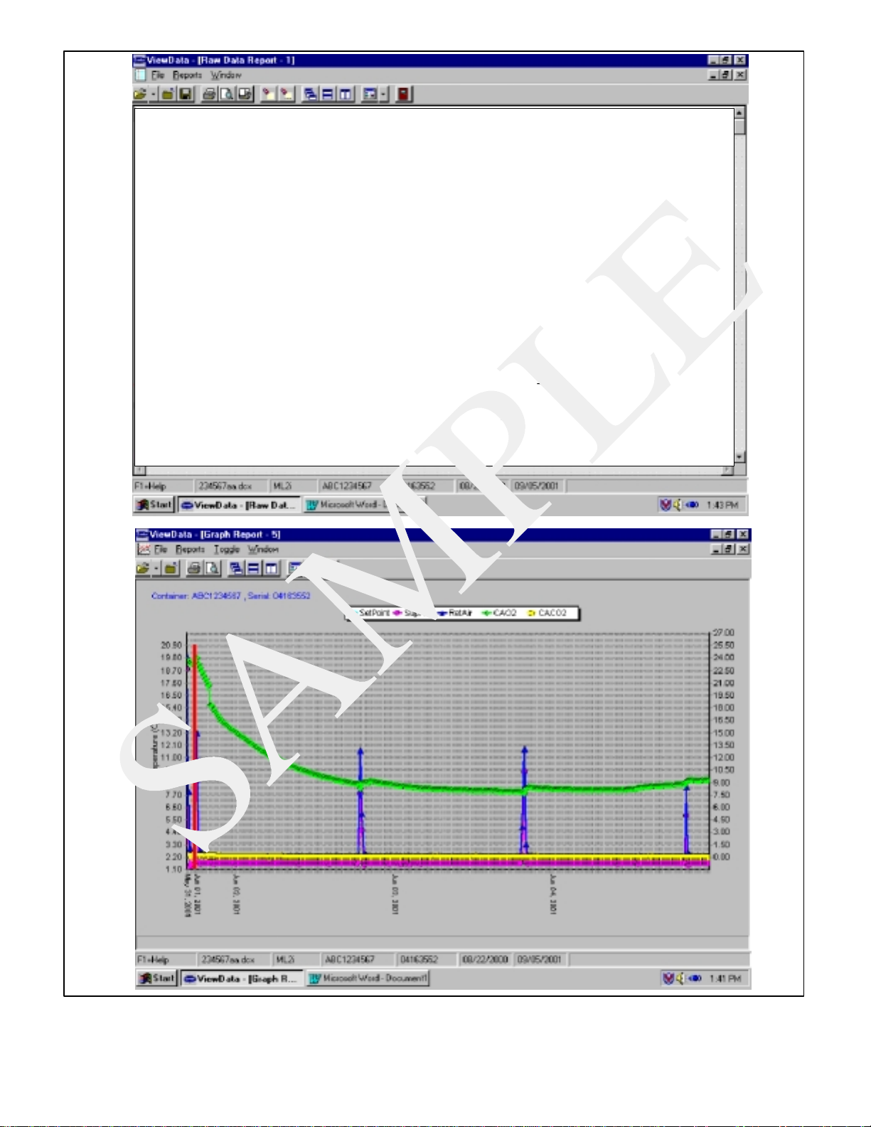
Raw Data Report for ABC1234567
May31, 2001 to Jun 04, 2001
SystemConfigurationat the TimeofInterrogation:
Interrogated On Sept 05, 2001
Extracted by DataLineRev 1.0.0
ControllerSoftware:5120
ControllerSerial#:04163552
Billof Lading#: 1
Origin: Origin Date:
Destination: Discharge Date:
Comment:DataLineTool
Probe Calibration Readings:USDA1: 0.0 USDA2: 0.0 USDA3: 0.0 Cargo: 0.0
Temperature Units: Centigrade
________________________________________________________________________________________
May31, 2001
Setpoint: 1.66,Container : Serial : 04189552
9 SensorsLogged at15 MinuteInterval
Sensor Format Resolution
Figure 3- 5 Standard Configuration Download Report
3-9
T-309
Page 35

3.6.4
Logging Interval (dCF03)
The user may select four different time intervals
between data recordings. Data is logged at exact
intervals in accordance with the real time clock. The
clock is factory set at Greenwich Mean Time (GMT).
3.6.5 Thermistor Format (dCF04)
The user may configure the format in which the
thermistorreadingsarerecorded. Theshortresolutionis
a1byteformatandthelongresolutionisa2byteformat.
Theshortrequireslessmemoryandrecordstemperature
in0.25°C(0.45°F)stepswhenintheperishablemodeor
0.5°C (0.9°F) steps when in the frozen mode. The long
records temperature in 0.01°C (0.02°F) steps for the
entire range.
3.6.6 Sampling Type (dCF05 & dCF06)
Three types of data sampling are available, average,
snapshot and USDA. When configured to average, the
average of readings taken every minute over the
recording period is recorded. When configured to
snapshot, the sensor reading at the log intervale time is
recorded. When USDA is configured the supply and
return temperature readings are averaged and the 3
USDA probe readings are snapshot.
3.6.7 Alarm Configuration (dCF07 -- dCF10)
The USDA and cargo probe alarms may be configured
to OFF, ON or AUTO.
Ifaprobealarm is configuredtoOFF,thenthealarmfor
this probe is always disabled.
Ifaprobealarm isconfiguredto ON, thentheassociated
alarm is always enabled.
If the probes are configured to AUTO, they act as a
group. This function is designed to assist users who
keep their DataCORDER configured for USDA
recording,but do not install the probes for everytrip. If
all theprobes aredisconnected, noalarms areactivated.
As soon as one of the probesis installed, then all of the
alarmsareenabledandtheremainingprobesthat arenot
installed will give active alarm indications.
The DataCORDER will record the initiation of a
pre-trip test (refer to paragraph 3.5) and the results of
each of the tests included in pre--trip. The data is
time-stamped and may be extracted via the Data
Retrievalprogram. Refer to Table 3-9 for a description
of the data stored in the DataCORDER for each
corresponding Pre-Trip test.
3.6.8
DataCORDER Power-Up
The DataCORDER may be powered up in any one of
four ways:
1. Normal AC power: The DataCORDER is powered
up when the unit is turned on via the stop-start switch.
2. ControllerDCbatterypackpower:Ifabatterypack
is installed, the DataCORDER will power up for
communicationwhenan interrogationcableis plugged
into an interrogation receptacle.
3. ExternalDC battery pack power: A 12 volt battery
pack may also be plugged into the back of the
interrogation cable, which is then plugged into an
interrogation port. No controller battery pack is
required with this method.
4. Real Time Clock demand: If the DataCORDER is
equipped with a charged battery pack and AC power is
not present, theDataCORDER will powerup whenthe
real time clock indicates that a data recording should
take place. When the DataCORDER is finished
recording, it will power down.
During DataCORDER power-up, while using
battery-pack power, the controller will perform a
hardware voltage check on the battery. If the hardware
checkpasses,theController willenergizeand performa
software battery voltage check before DataCORDER
logging. If either test fails, the real time clock battery
power-up will be disabled until the next AC power
cycle. FurtherDataCORDER temperaturelogging will
be prohibited until that time.
An alarm will be generated when the battery voltage
transitions from good to bad indicating that the battery
pack needs recharging. If the alarm condition persists
for more than 24 hours on continuous AC power, the
battery pack needs replacement.
3.6.9 Pre-Trip Data Recording
The DataCORDER will record the initiation of a
pre-trip test (refer to paragraph 3.5) and the results of
each of the tests included in pre--trip. The data is
time-stamped and may be extracted via the Data
Retrievalprogram. Refer to Table 3-9 for a description
of the data stored in the DataCORDER for each
corresponding Pre-Trip test.
3.6.10 DataCORDER Communications
Data retrieval from the DataCORDER can be
accomplished by using one of the following;
DataReader, DataLine/DataView or a communications
interfacemodule.
a. DataReader
The Carrier Transicold Data Reader (seeFigure 3- 6)is
asimpletooperatehandhelddevicedesignedtoextract
data from the DataCORDER and then upload it to a
personal computer. The Data Reader has the ability to
storemultipledatafiles.RefertoDataRetrievalmanual
62-02575 for a more detailed explanation of the
DataReader
3-10T-309
Page 36
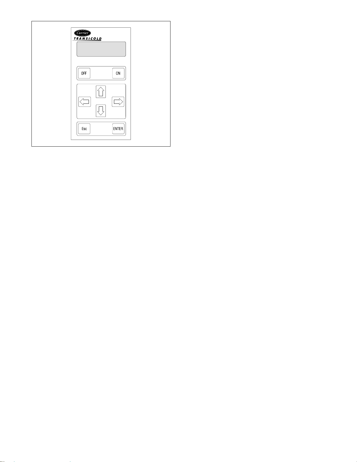
DataReader
Figure 3- 6 Data Reader
b. DataView
The DataView software for a personal computer is
supplied on a floppy disk. This software allows
interrogation, configuration variable assignment,
screen view of the data, hard copy report generation,
cold treatment probe calibration, cold treatment
initialization and file management. Refer to Data
Retrieval manual 62-02575 for a more detailed
explanation of the DataView interrogation software.
c. Communications Interface Module
The communications interface module is a slave
module which allows communication with a master
centralmonitoring station. The module will respond to
communication and return information over the main
power line.
With a remote monitoring unit installed, all functions
andselectablefeatures thatareaccessibleattheunitmay
be performed at the master station. Retrieval of all
DataCORDERreportsmayalso beperformed. Referto
the master system technical manual for further
information.
d. DataLine
The DataLINE software for a personal computer is
supplied on both floppy disks and CD. This software
allows interrogation, configuration variable
assignment, screen view of the data, hard copy report
generation, cold treatment probe calibration and file
management.RefertoDataRetrievalmanual62-10629
for a more detailed explanation of the DataLINE
interrogation software. The DataLine manual may be
found on the net at www.contaner.carrier.com
3.6.11 USDA Cold Treatment
Exposing infested fruit to temperatures of 2.2 degrees
Celsius (36_F) or below for specific periods results in
the mortality of the various stages of this group of
insects.
In response to the demand to replace fumigation with
this environmentally sound process, Carrier has
integrated Cold Treatment capability into its
microprocessorsystem. These units have the ability to
maintain supply air temperature within one-quarter
degreeCelsius ofsetpoint and recordminutechangesin
product temperature within the DataCORDER
memory, thus meeting USDA criteria. Information on
USDA is provided in the following subparagraphs
a. USDA Recording
A special type of recording is used for USDA cold
treatment purposes. Cold treatment recording requires
threeremotetemperatureprobes beplaced atprescribed
locations in the cargo. Provision is made to connect
these probes to the DataCORDER via receptacles
located at therearleft-handside ofthe unit.Four orfive
receptacles areprovided. Thefour three-pinreceptacles
are for the probes. The five pin receptacle is the rear
connection for the Interrogator. The probe receptacles
are sized to accept plugs with tricam coupling locking
devices. A label on the back panel of the unit shows
which receptacle is used for each probe.
Thestandard DataCORDER report displays the supply
and return air temperatures. The cold treatment report
displaysUSDA #1, #2, #3 andthe supplyand returnair
temperatures.Coldtreatment recordingis backed upby
abattery so recordingcan continue if AC power is lost.
b. USDA/ Message Trip Comment
Aspecialfeature is incorporatedin DataLine/DataView
which allows the user to enter a USDA (or other)
message in the header of a data report. The maximum
messagelengthis78 characters.Onlyone messagewill
be recorded per day.
3.6.12 USDA Cold Treatment Procedure
The following is a summary of the steps required to
initiate a USDA Cold Treatment.
a. Calibrate the three USDA probes by ice bathing the
probes and performing the calibration function with
the DataReader,DataVieworDataLine. Thiscalibration procedure determines the probe offsets and
storesthem in the controllerforuse in generatingthe
cold treatment report. Refer to the Data Retrieval
manual 62-02575 for more details.
b. Pre-coolthecontainertothetreatmenttemperatureor
below.
c..InstalltheDataCORDERmodulebatterypack(ifnot
already installed).
Sustained cold temperature has been employed as an
effective postharvest method for the control of
Mediterranean and certain other tropical fruit flies.
d. Place the threeprobes. The probes are placedinto the
pulpoftheproduct(atthelocationsdefinedinthefollowing table) as the product is loaded.
3-11
T-309
Page 37

Sensor 1
Place in pulp of the product located next
to the return air intake.
Place in pulp of the product five feet
from the end of the load for 40 foot con-
Sensor 2
tainers, or three feet from the end of the
load for 20 foot containers. This probe
should be placed in a center carton at
one-half the height of the load.
Place in pulp of product five feet from
the end of the load for 40 foot containers
Sensor 3
or three feet from the end of the load for
20 foot containers. This probe should be
placed in a carton at a side wall at onehalf the height of the load.
e. To initiate USDA Recording, connect the personal
computer and perform the configuration as follows,
using either the Data Viewor Data Line software:
1. Enter ISO header information
2. Enter a trip comment if desired
3. Configure the DataCORDER for five probes (s, r,
P1, P2, P3) (dcf02=5)
4. Configure the logging interval for one hour.
5. Set the sensor configuration to “USDA”.
6. Configure for two byte memory storage format
(dcf04=LONG).
7. Perform a “trip start”
3.6.13 DataCORDER Alarms
The alarm display i s an independent DataCORDER
function. If an operating parameter is outside of the
expected range or a component does not return the
correct values back to the DataCORDER an alarm is
generated.The DataCORDER contains a bufferofupto
eight alarms. A listing of the DataCORDER alarms is
provided in Table3-10, page 3-27. Refer to paragraph
3.6.7 for configuration information.
To display alarm codes:
a. While in the Default Display mode, press the ALT.
MODE&ALARMLISTkeys. Thisaccesses the DataCORDER Alarm List Display Mode, which displays any alarms stored in the Alarm Queue.
b. ToscrolltotheendofthealarmlistpresstheUP AR-
ROW. Depressing the DOWN ARROW key will
scroll the list backward.
c. The left display will show “AL#” where # is the
alarms number in the queue. The right display will
show “AA##,” ifthealarm is active, where ## is the
alarmnumber.“IA##,”willshowifthealarmisinactive
d. “END” is displayed to indicate the end of the alarm
list if any alarms are active. “CLEAr” is displayedif
all the alarms in the list are inactive.
e. If no alarms are active, the Alarm Queue may be
cleared. The exception to thisrule is the DataCORDERAlarm QueueFull alarm(AL91),whichdoesnot
haveto be inactive in order to clear thealarm list. To
Clear the Alarm List:
1. Press the ALT. MODE & ALARM LIST keys.
2. PresstheUP/DOWNARROWkeyuntil “CLEAr”is
displayed.
3. Press the ENTER key. The alarm list will clear and
-- -- -- -- -- ” will be displayed.
“
4. Pressthe ALARM LIST key.“AL” will show on the
leftdisplayand“
-- -- -- -- -- ”ontheright displaywhen
there are no alarms in the list.
5. Upon clearing of the Alarm Queue, the Alarm light
will be turned off.
3.6.14 ISO Trip Header
DataLine provides the user with an interface to
view/modify current settings of the ISO trip header
through the ISO TripHeader screen.
TheISO TripHeaderscreen is displayed when the user
clicks on the “ISO Trip Header” button in the “Trip
Functions” Group Box on the System Toolsscreen.
F9 function -- Provides the user with a shortcut for
manually triggering the refresh operation.Before
sending modified parameter values, the user must
ensure that a successful connection is established with
the Controller.
IftheconnectionisestablishedwiththeDataCorder,the
current contents of the ISO Trip Header from the
DataCorder will be displayed in each field. If the
connection is not established with the DataCorder, all
fields on the screenwill be displayed as “X’s”.Ifat any
time during the display of the ISO Trip Header screen
the connection is not established or is lost, the user is
alerted to the status of the connection.
After modifying the values and ensuring a successful
connectionhas been madewiththeDataCorder,clickon
the “Send” button to send the modified parameter
values.
Themaximumallowed lengthof theISOTrip Header is
128 characters.If the user tries to refresh the screen or
close the utility without sending the changes made on
the screen to the DataCorder, the user is alerted with a
message.
3-12T-309
Page 38

Table 3-4 Controller Configuration Variables
NOTES
1. Configuration numbers not listed are not used in this application. These items may appear when loading
configurationsoftware to the controllerbut changes will not be recognized by the controller programming.
CONFIGURATION
NUMBER
TITLE DEFAULT OPTION
CnF02 Evaporator Fan Speed dS (Dual) SS (Single)
CnF04 Dehumidification Mode On OFF
CnF11 Defrost “Off” Selection noOFF OFF
CnF16 DataCORDER Present On (Yes) OFF (No)
CnF22 Economy Mode Option OFF Std, Full
CnF23 Defrost Interval Timer Save Option noSAv SAv
CnF24 Long Pre Trip Test Sequence Enabled On Off
CnF25 Pre-T rip Te st Points/Results Recording Option rSLtS dAtA
CnF26 Heat Lockout Change Option Set to --10_C Set to --5_C
CnF28 Bulb Mode Option NOr bULb
CnF31 Probe Check Option Std SPEC
CnF33 Snap Freeze Option OFF SnAP
CnF34 Degree Celsius Lockout Option bOth _F
CnF37 Electronic Temperature Recorder rEtUR (Return) suPPl, BOth
3-13
T-309
Page 39

Table 3-5 Controller Function Codes (Sheet 1 of 3)
Code
No.
TITLE DESCRIPTION
Note: If the function is not applicable, the display will read “-- -- -- -- --”
Display Only Functions
Cd01
Suction Modulation
Valve Opening (%)
Cd02 Not Applicable Not used
Cd03
Cd04
Compressor Motor
Current
Line Current,
PhaseA
Cd05
Line Current,
PhaseB
Cd06
Line Current,
PhaseC
Cd07 Main Power Voltage The main supply voltage is displayed.
Cd08
Cd09
Cd10
Cd11
Cd12
Main Power Fre-
quency
Ambient Tempera-
ture
Compressor Suction
Temperature
Compressor Dis-
charge Temperature
Compressor Suction
Pressure
Cd13 Not Applicable Not used
Cd14
Compressor Dis-
charge Pressure
Cd15 Unloader Valve The status of the valve is displayed (Open - Closed).
Cd16
Cd17
Compressor Motor
Hour Meter
Relative Humidity
(%)
Cd18 Software Revision # Thesoftware revision number is displayed.
Cd19 Battery Check
Cd20 Config/Model #
Cd21 Economizer Valve The status of the valve is displayed (Open - Closed).
Displays the SMV percent open. The right display reads 100% when the valve is
fully open. The valve will usually be at 10% on start up of the unit except in very
high ambient temperatures.
The current sensor measures current draw in lines L1 & L2 by all of the high
voltage components. It also measures current draw in compressor motor leg T3.
The compressor leg T3 current is displayed.
The current sensor measures current on two legs. The third unmeasured leg is calculated based on a current algorithm. The current measured is used for control
and diagnostic purposes. For control processing, the highest of the Phase A and B
current values is used for current limiting purposes. For diagnostic processing,
the current draws are used to monitor component energization.. Whenever a heater or a motor is turned ON or OFF, the current draw increase/reduction for that
activity is measured. The current draw is then tested to determine if it falls within
the expected range of values for the component. Failure of this test will result in a
pre-trip failure or a control alarm indication.
The value of the main power frequency is displayed in Hertz. The frequency displayed will be halved if either fuse F1 or F2 is bad (alarm code AL21).
The ambient sensor reading is displayed.
Compressor suction temperature sensor reading i s displayed.
Compressor discharge temperature sensor reading is displayed.
Compressor suction pressure transducer reading is displayed.
Compressor discharge pressure transducer reading is displayed.
Records total hours of compressor run time. Totalhours are recordedin increments of 10 hours (i.e., 3000 hours is displayed as 300).
Humidity sensor reading is displayed. This code displays the relative humidity, as
a percent value.
This code checks the Controller/DataCORDER battery pack. While the t est is
running, “btest” will flash on the right display, followed by the result. “PASS”
will be displayed for battery voltages greater than 7.0 volts. “FAIL” will be displayed for battery voltages between 4.5 and 7.0 volts, and “-- -- -- -- --” will be
displayed for battery voltages less than 4.5 volts. After the result is displayed for
four seconds, “btest” will again be displayed, and the user may continue to scroll
through the various codes.
This code indicates the dash number of the model for which the Controller is configured (i.e., if the unit is a 69NT40-531-100, the display will show “31100”).
3-14T-309
Page 40

Table 3-5 Controller Function Codes (Sheet 2 of 3)ff
Cd22 Compressor State The status of the compressor is displayed (Off, On).
Cd23 Evaporator Fan Displays the current evaporator fan state (high, low or off).
Cd24
Cd25
Cd26
Controlled
Atmosphere State
Compressor Run
TimeRemaining
Until Defrost
Defrost Temperature
Sensor Reading
Not used in this application
This code displays the time remaining until the unit goes into defrost (in tenths of
an hour). This value is based on the actual accumulated compressor running time.
Defrost temperature sensor reading is displayed.
Configurable Functions
NOTE
Function codes Cd27 through Cd37 are user-selectable functions. The operator can change the value of
these functions to meet the operational needs of the container.
The defrost interval is the time between defrost cycles. Five selectablevalues are
available: 3, 6, 9, 12 or 24 hours. The factory default value is 12 hours. Following a start--up or after termination of a defrost, the time will not begin counting
down until the defrost temperaturesensor (DTS) reading falls below set point. If
the reading of DTS rises above set point any time during the timer count down,
the interval is reset and the countdown begins over. If DTS fails, alarm code
AL60 is activated and control switches over to the the return temperature sensor.
The controller will act in the same manner as with the DTS except the return temperaturesensor reading will be used.
DefrostInterval Timer Value(Configuration variable CnF23): If the softwareis
configured to “SAv” (save) for this option, then the value of the defrost interval
timer will be saved at power down and restored at power up. This option prevents
short power interruptions from resetting an almost expired defrost interval, and
possibly delaying a needed defrost cycle.
Cd27
Defrost Interval
(Hours)
Cd28
Cd29
TemperatureUnits
(_Cor_F)
Failure Action
(Mode)
Cd30 In-Range Tolerance
NOTE
The defrost interval timer counts only during compressor run time.
This code determines the temperature units (_Cor_F) which will be used for all
temperature displays. The user selects _Cor_F by selecting function code Cd28
and pushing the ENTER key. The factory default value is Celsius units.
NOTE
This function code will display “--- --- --- --- --- “ if Configuration Variable
CnF34 is set to _F.
If all of the control sensors are out of range (alarm code AL26) or there is a probe
circuit calibration failure (alarm code AL27), the unit will enter the shutdown
state defined by this setting. The user selects one of four possible actions as follows:
A-- FullCooling(compressorison,economizedoperation.SMVsubjecttopressure
and current limit.)
B -- PartialCooling(Compressoris on,standardoperation.SMVsubjecttopressure
and current limit.)
C -- EvaporatorFanOnly (Compressor is off,evaporator fans on high speed, not ap-
plicable with frozen set points.
D -- Full System Shutdown -- Factory Default (shut down every component in the
unit)
The in-range tolerance will determine the band of temperaturesaround the set
point which will be designated as in-range. If the control temperature is in-range,
the in-range light will be illuminated. There are four possible values:
1=¦ 0.5_C(¦ 0.9_F)
2=¦ 1.0_C(¦ 1.8_F)
3=¦ 1.5_C(¦ 2.7_F)
4=¦ 2.0_C(¦ 3.6_F) -- Factory Default
3-15
T-309
Page 41

Table 3-5 Controller Function Codes (Sheet 3 of 3)
The stagger start offset time is the amount of time that the unit will delay at start-
Cd31
Stagger Start Offset
Time(Seconds)
up, thus allowing multiple units to stagger their control initiation when all units
are powered up together.The eight possible offset values are:
0 (Factory Default), 3, 6, 9, 12, 15, 18 or 21 seconds
The current limit is the maximum current draw allowed on any phase at any time.
Limiting the unit’s current reduces the load on the main power supply. This is
Cd32
Current Limit
(Amperes)
accomplished by reducing the SMV position until current draw is reduced to the
set point. When desirable, the limit can be lowered. Note, however, that capacity
is also reduced. The five values for 460vac operation are: 15, 17, 19, 21 (Factory
Default), 23
Relative humidity set point is available only on units configured for dehumidification. When the mode is activated, the control probe LED flashes on and off every second to alert the user. If not configured, the mode is permanently deactivated and “-- -- -- -- --”willdisplay.Thevaluecanbesetto“OFF.”“TEST,”ora
range of 65 to 95% relative humidity in increments of 1%. [If bulb mode is active
(code Cd35) and “Lo” speed evaporator motors are selected(code Cd36) then set
point ranges from 60 to 95%.] When “TEST” is selected or test set point is
Cd33
Perishable Mode
Dehumidification
Control (% RH)
entered, the heat LED should illuminate, indicating that dehumidification mode is
activated. After a period of five minutes in the “TEST” mode has elapsed, the
previously selected mode is reinstated.
Cd34
Economy Mode
(On--Off)
Economy mode is a user selectable mode of operation provided for power saving
purposes.
Bulb mode is a user selectable mode of operation that is an extension of dehumidification control (Cd33). If dehumidification is set to “Off,” code Cd35 will
Cd35 Bulb Mode
display “Nor” and the user will be unable to change it. After a dehumidification
set point has been selected and entered for code Cd33, the user may then change
code Cd35 to “bulb.” After bulb has been selected and entered, the user may then
utilize function codes Cd36 and Cd37 to make the desired changes.
This code is enabled only if in the dehumidification mode (code Cd33) and bulb
mode (Cd35) has been set to “bulb”. If these conditions are not met, “alt” will be
displayed (indicating that the evaporator fans will alternate their speed) and the
Cd36
Evaporator Speed
Select
display cannot be changed. If a dehumidification set point has been selected along
with bulb mode then “alt” may be selected for alternating speed, “Lo” for low
speed evaporator fan only, or “Hi” for high speed evaporator fan only. If a setting
other than “alt” has been selected and bulb mode is deactivated in any manner,
then selection reverts back to “alt.”
This code, as with function code Cd36, is used with bulb mode and dehumidification. If bulb mode is active, this code allows the user to change the temperature
defrost will terminate. It allows the user to change the setting within a range of
4_C to 25.6_Cin0.1_C (0.2_F) increments. This value is changed using the UP/
DOWN ARROW keys, followed by the ENTER key when the desired value is
Cd37
Defrost Termination
TemperatureSetting
(Bulb Mode)
displayed. If bulb mode is deactivated, the DTS setting returns to the default.
Display Only Functions -- Continued
Code Cd38 will display the current secondary supply temperature sensor reading
Cd38
Cd39
Cd40
Secondary Supply
Temperature Sensor
Secondary Return
Temperature Sensor
Container Identifica-
tion Number
Cd41 ValveOverride
Cd42 Oil Return Valve The status of the valve is displayed (Open - Closed).
for units configured for four probes. If the unit is configured with a DataCORDER, Cd38 will display “-- -- -- -- -- .” If the DataCORDER suffers a failure,
(AL55) Cd38 will display the supply recorder sensor reading.
Code Cd39 will display the current secondary return temperature sensor reading
for units configured for four probes. If the unit is configured with a DataCORDER, Cd39 will display “-- -- -- -- -- .” If the DataCORDER suffers a failure,
(AL55) Cd39 will display the return recorder sensor reading.
Code Cd40 is configured at commissioning to read a valid container identification number. The reading will not display alpha characters,only the numeric portion of the number will display.
SERVICE FUNCTION: This code is used for troubleshooting and allows manual positioning of the economizer, unloader, suction modulation and oil return
valves. Refer to paragraph 6.19 for operating instructions.
3-16T-309
Page 42

Table 3-6 Controller Alarm Indications (Sheet 1 of 4)
Code
No.
TITLE DESCRIPTION
Alarm 13 is triggered if the control module has lost communication with the expansion module for more than five minutes or communication fails within the
AL13 Expansion Module
first 15 seconds on power up. This alarm triggers failure action C (evaporator fan
only) or D (all machinery off) of Function Code Cd29 if the unit has a perishable
set point. Failureaction D (all machinery off) is triggered i f the unit has a frozen
set point
Alarm 14 is triggered if the electronic phase detection system is unable to determine the correct phase relationship. DIRCHECK will be displayed while the
relationship i s determined. If the system is unable to determine the proper relationship alarm 14 will remain active. Additiotnal information on phase detection
may be displayed at Function C ode Cd41. If the right most digit of Code Cd41 is
AL14
Phase Sequence
Failure -- Electronic
3 or 4, this indicates incorrect motor or sensor wiring. If the right most digit is 5,
this indicates a failed current sensor assembly.
AL15 Loss Cooling Future Expansion
Alarm 16 is triggered if compressor current draw is 15% over calculated maximum for 10 minutes out of the last hour. The alarm is display only and will trigger off when the compressor operates for one hour without over current.
AL16
Compressor Current
High
Alarm 17 is triggered if a compressor start in both directions fails to generate
sufficient pressure differential. The controller will attempt restart every twenty
AL17
Phase Sequence
Failure -- Pressure
minutes and deactivate the alarm if successful. This alarm triggers failure action
C (evaporator fan only) or D (all machinery off) of Function Code Cd29 if the
unit has a perishable set point. Failure action D (all machinery off) is triggered if
the unit has a frozen set point
Alarm 18 is triggered if discharge pressure is 10% over calculated maximum for
10 minutes within the last hour. The alarm is display only and will trigger off
when the compressor operates for one hour without overpressure.
Alarm 19 is triggered if discharge temperature exceeds 135_C (275_F) for 10
minutes within the last hour. The alarm is display only and will trigger off when
the compressor operates for one hour without over temperature.
Alarm 20 is triggered by control power fuse (F3) opening and will cause the software shutdown of all control units. This alarm will remain active until the fuse is
replaced.
AL18
AL19
AL20
DischargePressure
High
DischargeTempera-
ture High
Control Circuit Fuse
Open (24 vac)
Alarm 21 is triggered by one of the fuses (F 1/F2) being opened on 18 volts AC
AL21
Micro Circuit Fuse
Open (18 vac)
power supply to the Controller.The suction modulation valve (SMV) will be
opened and current limiting is halted. Temperature control will be maintained by
cycling the compressor.
Alarm 22 responds to the evaporator motor internal protectors. The alarm is triggered by opening of either internal protector. It will disable all control units until
the motor protector resets and the unit is power cycled.
AL22
Evaporator Fan Mo-
tor Safety
Alarm 23 is triggered if low current draw is detected on phase B and IPCP, HPS
or IPEM is not tripped. If the compressor should be running, the controller will
initiate a start up every five minutes and trigger off if current reappears. If the
AL23 Loss of Phase B
evaporator fan motors only should be running, the alarm will trigger off is current reappears. This alarm triggers failure action C (evaporator fan only) or D
(all machinery off) of Function Code Cd29 if the unit has a perishable set point.
Failure action D (all machinery off) is triggered if t he unit has a frozen set point
Alarm 24 is triggered when compressor is not drawing any current. It also trig-
AL24
Compressor Motor
Safety
gers failure action ”C” or ”D” set by function Code 29 for perishable setpoint, or
”D” for frozen setpoint. This alarm will remain active until compressor draws
current.
3-17
T-309
Page 43

AL25
Condenser Fan Mo-
tor Safety
All Supply and Re-
AL26
turn temperature
Control Sensors
Failure
AL27
AL28
A/D Accuracy Fail-
ure
Low Suction Pres-
sure
AL51 AlarmList Failure
AL52 AlarmListFull
AL53 Battery Pack Failure
Primary Supply
AL54
Temperature Sensor
Failure (STS)
Table 3-6 Controller Alarm Indications (Sheet 2 of 4)
Alarm 25 is triggered by the opening of the condenser motor internal protector
and will disable all control units except for the evaporator fans. This alarm will
remain active until the motor protector resets. This alarm triggers failure action
C (evaporator fan only) or D (all machinery off) of Function Code Cd29 if the
unit has a perishable set point. Failure action D (all machinery off) is triggered if
the unit has a frozen set point
Alarm 26 is triggered if the Controller determines that all of the control sensors
are out-of-range. This can occur for box temperatures outside the range of --50_C
to +70_C(--58_F to +158_F). This alarm triggers the failure action code set by
Function Code Cd29.
The Controller has a built-in Analog to Digital (A-D) converter, used to convert
analog readings (i.e. temperature sensors, current sensors, etc.) to digital readings. The Controller continuously performs calibration tests on the A-D converter. If the A-D converter fails to calibrate for 30 consecutive seconds, this
alarm is activated.This alarm will be inactivated as soon as the A-D converter
calibrates.
Alarm 28 is triggered i f suction pressure is below 2 psia and alarm 66 (Suction
Pressure Transducer Failure) is not active. This alarm will be inactivated when
suction pressure rises above 2 psia for three continuous minutes. This alarm triggers failure action C (evaporator fan only) or D (all machinery off) as determined
by User Selectable Failure Response if the unit has a perishable set point; Failure
action D (all machinery off) if the unit has a frozen set point. Reset SMV.
During start-up diagnostics, the EEP ROM is examined to determine validity of
its contents. This is done by testing the set point and the alarm list. If the contents are invalid, Alarm 51 is activated. During control processing, any operation
involving alarm list activity that results in an error will cause Alarm 51 to be activated. Alarm 51 is a “display only” alarm and is not written i nto the alarm list.
Pressing the ENTER key when “CLEAr” is displayed will result in an attempt to
clear the alarm list. If that action is successful (all alarms are inactive), Alarm 51
will be reset.
Alarm 52 is activated whenever the alarm list is determined to be full; at start-up
or after recording an alarm in the list. Alarm 52 is displayed, but is not recorded
in the alarm list. This alarm can be reset by clearing the alarm list. This can be
done only if all alarms written in the list are inactive.
Alarm 53 is caused by the battery pack charge being too low to provide sufficient
power for battery-backed recording. Renew replaceable batteries. If this alarm
occurs on start up, allow a unit fitted with rechargeable batteries to operate for up
to 24 hours to charge rechargeable batteries sufficiently to deactivate the alarm
Alarm 54 is activated by an invalid primary supply temperature sensor reading
that is sensed outside the range of --50 to +70_C(--58_F to +158_F) or if the
probe check logic has determined there is a fault with this sensor. If Alarm 54 is
activated and the primary supply is the control sensor, the secondary supply sensor will be used for control if the unit is so equipped. If the unit does not have a
secondary supply temperature sensor, and AL54 is activated, the primary return
sensor reading, minus 2_C will be used for control.
NOTE
AL55
DataCORDER
Failure
The P5 Pre-Trip test must be run to inactivate the alarm
This alarm activates to indicate the DataCORDER has a software failure. To
clear this alarm, reconfigure the unit to the current model number. This failure
may be the result of a voltage dip in access of 25%.
3-18T-309
Page 44

Primary Return
AL56
Temperature Sensor
Failure (RTS)
AL57
AL58
AL59
AL60
Ambient Tempera-
ture Sensor Failure
Compressor High
Pressure Safety
Heat Termination
Thermostat
Defrost Temperature
Sensor Failure
AL61 Heaters Failure
AL62
Compressor C ircuit
Failure
AL63 CurrentOver Limit
AL64
AL65
AL66
AL67
AL69
DischargeTempera-
ture Over Limit
DischargePressure
Transducer Failure
Suction Pressure
Transducer Failure
Humidity Sensor
Failure
Suction Temperature
Sensor Failure
Table 3-6 Controller Alarm Indications (Sheet 3 of 4)
Alarm 56 is activated by an invalid primary return temperature sensor reading
that is outside the range of --50 to +70_C(--58_F to +158_F). If Alarm 56 is acti-
vated and the primary return is the control sensor, the secondary return sensor
will be used for control if the unit is so equipped. If the unit is not equipped with
a secondary return temperaturesensor or it fails, the primary supply sensor will
be used for control.
NOTE
The P5 Pre-Trip test must be run to inactivate the alarm.
Alarm 57 is triggered by an ambient temperature reading outside the valid range
from --50_C(--58_F) to +70_C (+158_F).
Alarm 58 is triggered when the compressor high discharge pressure safety switch
remains open for at least one minute. This alarm will remain active until the pressure switch resets, at which time the compressor will restart.
Alarm 59 is triggered by the opening of the heat termination thermostat and will
result in the disabling of the heater. This alarm will remain active until the thermostat resets.
Alarm 60 is an indication of a probable failure of the defrost temperature sensor
(DTS). It is triggered by the opening of the heat termination thermostat(HTT) or
the failure of the DTS to go above set point within two hours of defrost initiation. After one-half hour with a frozen range set point, or one-half hour of continuous compressor run time, if the return air falls below 7_C(45_F), the Controller
checks to ensure the DTS reading has dropped to 10_C or below. If not, a DTS
failure alarm is given and the defrost mode is operated using the return temperature sensor. The defrost mode will be terminated after one hour by the C ontroller.
Alarm 61 is triggered by detection of improper amperage resulting from heater
activation or deactivation. Each phase of the power source is checked for proper
amperage.Thisalarm is a display alarm with no resulting failure action, and will
be reset by a proper amp draw of the heater.
Alarm 62 is triggered by improper current draw increase (or decrease) resulting
from compressor turn on (or off). The compressor is expected to draw a minimum of 2 amps; failure to do so will activate the alarm. This is a display alarm
with no associated failure action and will be reset by a proper amp draw of the
compressor.
Alarm 63 is triggered by the current limiting system. If the compressor is ON
and current limiting procedures cannot maintain a current level below the user
selectedlimit, the current limit alarm is activated. This alarm is a display alarm
and is inactivated by power cycling the unit, changing the current limit via the
code select Cd32, or if the current decreases below the activation level.
Alarm 64 is triggered if the discharge temperature sensed is outside the range of
-- 6 0 _C(--76_F) to 175_C (347_F), or if the sensor is out of range. This is a dis-
play alarm and has no associated failure action.
Alarm 65 is triggered if a compressor discharge transducer is out of range. This is
a display alarm and has no associated failure action.
Alarm 66 is triggered if a suction pressure transducer is out of range. This is a
display alarm and has no associated failure action.
Alarm 67 is triggered by a humidity sensor reading outside the valid range of 0%
to 100% relative humidity. If alarm AL67 is triggered when the dehumidification
mode is activated, then the dehumidification mode will be deactivated.
Alarm 69 is triggered by a suction temperaturesensor reading outside the valid
range of --60_C(--76_F) to 150_C (302_F). This is a display alarm and has no
associated failure action.
3-19
T-309
Page 45

Table 3-6 Controller Alarm Indications (Sheet 4 of 4)
ERR#M
i
NOTE
If the Controlleris configured for four probes without a DataCORDER, the DataCORDER alarms AL70
and AL71 will be processed as Controller alarms AL70 and AL71. Referto Table 3-10.
The Controller performs self-check routines. if an internal failure occurs, an
“ERR” alarm will appear on the display. This is an indication the Controller
needs to be replaced.
ERROR DESCRIPTION
Indicates that the Controller working memory has
failed.
Indicates a problem with the Controller program.
The Controller program has entered a mode whereby
the Controller program has stopped executing.
The on board timers are no longer operational.
Timed items such as; defrost, etc. may not work.
Internal multi-purpose counters have failed. These
counters are used for timers and other items.
The Controller’s Analog to Digital (A-D) converter
has failed.
ERR
Entr
StPt
Internal
croprocessor
Failure
Enter Setpoint
(Press Arrow &
Enter)
ERR 0 -- RAM failure
EER 1 -- Program
Memory failure
EER 2 -- Wa tchdog
time--out
EER 3 -- On board timer
failure
EER 4 -- Internal counter
failure
EER 5 -- A-D failure
The Controller is prompting the operator to enter a set point.
Low Main Voltage
(Function Codes
LO
Cd27--38 disabled
and NO alarm
This message will be alternately displayed with the set point whenever the supply voltage is less than 75% of its proper value.
stored.)
3-20T-309
Page 46

Table 3-7 Controller Pre-Trip Test Codes (Sheet 1 of 4)
Code
No.
TITLE DESCRIPTION
“Auto” or “Auto1” menu includes the: P0, P1, P 2, P3, P4, P5, P6 and rSLts. “Auto2” menu
includes P0, P1, P2, P3, P4, P5, P6, P7, P8, P9, P10 and rSLts.
P0--0 Pre-TripInitiated
P1-0 Heaters Turned On
P1-1 Heaters Turned Off
P2-0 Condenser Fan On
P2-1 CondenserFan Off
Low Speed Evapora-
P3
P3-0
P3-1
P4-0
P4-1
P5-0
tor Fans
Low Speed Evapora-
tor Fan Motors On
Low Speed Evapora-
tor Fan Motors Off
High Speed Evapo-
rator Fan Motors On
High Speed Evapo-
rator Fan Motors Off
Supply/Return Probe
Test
NOTE
All lights and display segments will be energized for five seconds at the start of
the pre-trip. Since the unit cannot recognize lights and display failures, there are
no test codes or results associated with this phase of pre-trip.
Setup: Heater must start in t he OFF condition, and then be turned on. A current
draw test is done after 15 seconds.
Pass/Fail Criteria: Passes if current draw change is within the range specified.
Setup: Heater must start in the ON condition, and then be turned off. A current
draw test is done after 10 seconds.
Pass/Fail Criteria: Passes if current draw change is within the range specified.
Requirements: Waterpressure switch or condenser fan switch input must be
closed.
Setup: Condenser fan is turned ON, a current draw test is done after 15 seconds.
Pass/Fail Criteria: Passes if current draw change is within the range specified.
Setup: Condenser fan i s turned OFF, a current draw test is done after 10 sec-
onds.
Pass/Fail Criteria: Passes if current draw change is within the range specified.
Requirements: The unit must be equipped with a low speed evaporator fan, as
determined by the Evaporator Fan speed select configuration variable.
Setup: The high speed evaporator fans will be turned on for 10 seconds, then off
for two seconds, then the low speed evaporator fans are turned on. A current
draw test is done after 60 seconds.
Pass/Fail Criteria: Passes if change in current draw is within the range specified. Fails if AL11 or AL12 activates during test.
Setup: The low speed Evaporator Fan is turned off, a current draw test is done
after 10 seconds.
Pass/Fail Criteria: Passes if change in current draw is within the range specified. Fails if AL11 or AL12 activates during test.
Setup: The high speed Evaporator Fan is turned on, a current draw test is done
after 60 seconds.
Pass/Fail Criteria: Passes if change in current draw is within the range specified. Fails if AL11 or AL12 activates during test.
Setup: The high speed Evaporator Fan is turned off, a current draw test is done
after 10 seconds.
Pass/Fail Criteria: Passes if change in current draw is within the range specified. Fails if AL11 or AL12 activates during test.
Setup: The High Speed Evaporator Fan is turned on and run for eight minutes,
with all other outputs de-energized.
Pass/Fail Criteria: A temperature comparison is made between the return and
supply probes.
NOTE
If this test fails, “P5-0” and “FAIL” will be displayed. If both Probe tests
(this test and the PRIMARY/ SECONDARY) pass, the display will read
“P5” “PASS.”
3-21
T-309
Page 47

Table 3-7 Controller Pre-Trip Test Codes (Sheet 2 of 4)
Requirements: For units equipped with secondary supply probe only.
Pass/Fail Criteria: The temperature difference between primary and secondary probe
(supply) is compared.
P5-1 Supply P robe Test
P5-2 Return Probe Test
Refrigerant Probes,
P6
Compressor
and
Refrigeration valves
P6-0
P6-1
P6-2
P6-3
P6-4
P6-5
P6-6
Discharge
Thermistor Test
Suction
Thermistor Test
DischargePressure
Sensor Test
Suction Pressure
Sensor Test
Compressor Current
Draw Test
Suction Modulation
Valve Test
Economizer
Valve Test
P6-7 Unloader Valve Test
NOTE
Ifthistestfails,“P5-1”andFAILwill be displayed. If both Probetests(this
andtheSUPPLY/RETURN TEST) pass, becauseof themultiple tests,the
display will read ’P 5’ ’PASS’.
Requirements: For units equipped with secondary return probe only.
Pass/Fail Criteria: The temperature differenc e between primary and secondary
probe (return) is compared.
NOTES
1. If this test fails, “P5-2”and “FAIL” will be displayed. If bothProbetests
(this test and the SUPPLY/ RETURN) pass, because of the multiple
tests, the display will read “P 5,” “PASS.”
2. The results of Pre-Trip tests 5-0, 5-1 and 5-2 will be used to activate or
clear control probe alarms.
Setup: The system is operated through a sequence of events to test the components. The sequence is: Step 1, de--energize all outputs; Step 2, start unit with
unloader valve open. Open then close the suction modulation valve. Monitor
suction pressure; Step 3, open suction modulation valve to a known position;
Step 4, close suction modulation valve to a know position; Step 5, open economizer valve; Step 6, close unloader valve; Step 7, open unloader valve; Step 8,
close economizer valve; Step 9, de--energize all outputs.
If alarm 64 is activated any time during the first 45 second period of Step 1, the
test fails.
If alarm 69 is activated any time during the first 45 second period of Step 1, the
test fails.
If alarm 65 is activated any time during the first 45 second period of Step 1, the
test fails.
If alarm 66 is activated any time during the first 45 second period of Step 1, the
test fails.
Compressor current is tested before and after start up. If current does not increase, the test fails.
Suction pressure is measured before and after the valve opens. If suction pressure does not increase, the test fails.
Suction pressure is measured during Steps 4 and 5. If suction pressure does not
increase, the test fails.
Suction pressure is measured during Steps 6 and 7. If suction pressure does not
increase, the test fails.
3-22T-309
Page 48

Table 3-7 Temperature Controller Pre-Trip Test Codes (Sheet 3 of 4)
g
P7-0
P7-1
P8-0
P8-1
High Pressure
Switch Closed
High Pressure
Switch Open
Perishable Mode
Heat Test
Perishable Mode
Pull Down Test
Perishable Mode
P8-2
Maintain Tempera-
ture Test
P9-0 Defrost Test
NOTE
P7-0 through P10 are included with the “Auto2” only.
NOTE
This test is skipped if the sensed ambient temperature is less than 7_C
(45_F), the return air temperature is less than --17.8_C(0_F), the water
pressure switch is open or the condenser fan switch is open.
Setup: With the unit running, the condenser fan is de-energized, and a 15 minute
timer is started.
Pass/Fail Criteria: The t est fails if high pressure switch fails to open in 15 minutes.
Requirements: Test P7-0 must pass for this test to execute. Setup: The condenser fan is started and a 60 second timer is started.
Pass/Fail Criteria: Passes the test if the high pressure switch (HPS) closes
within the 60 second time limit, otherwise, it fails.
Setup: If the container temperature is below 15.6°C(60_F), the set point is
changed to 15.6°C, and a 180 minute timer is started. The left display will read
“P8-0.” The control will then heat the container until 15.6°C is reached. If the
container t emperature is above 15.6°C at the start of the test, then the test proceeds immediately to test P8-1 and the left display will change to “P8-1.”
Pass/Fail Criteria: The test fails if the 180 minute timer expires before the control temperature reaches set point. The display will read “P8-0,” “FAIL.”
Requirements: Control temperature must be at least 15.6°C(60_F).
Setup: The set point is changed to 0°C(32_F), and a 180 minute timer is
started. The left display will read “P8-1,” the right display will show the supply
air temperature. The unit will then start to pull down the temperature to the 0°C
set point.
Pass/Fail Criteria: The test passes if the container temperature reaches set point
before the 180 minute timer expires.
Requirements: Test P8-1 must pass for this test to execute. This test is skipped
if the DATAcorder is not configured or available.
Setup: The left display will read “P8-2,” and the right display will show the supply air temperature. A two hour timer is started. The unit will be required to
maintain the temperatureto within + or -- 0.5_C (0.9_F) of set point until a DataCORDER recording is executed. The recordersupply probe temperature running total (and its associated readings counter) will be zeroed out for the remainder of the recording period at the start of this test, so that the actual value
recorded in the DataCORDER will be an average of only this test’s results. Once
a recording interval is complete, the average recorder supply temperature will be
recorded in the DataCORDER, as well as stored in memory for use in applying
the test pass/fail criteria.
Pass/Fail Criteria: If the recorded temperature is within +/-- 0.5_C. of set point
from test start to DataCORDERrecording, the test passes. If the average temperature is outside of the tolerance range at the recording, the test fails and will
auto--repeat by starting P8--0 over.
Setup: The defrost temperature sensor (DTS) reading will be displayed on the
left display. The right display will show the supply air temperature.The unit will
run FULL COOL for 30 minutes maximum until the DTT is considered closed.
Once the DTT is considered closed, the unit simulates defrost by running the
heaters for up to two hours, or until the DTT is considered open.
Pass/Fail Criteria: The test fails if: the DTT is not considered closed after the
30 minutes of full cooling, HTT opens when DTT is considered closed or if return air temperature rises above 49/50_C (120/122_F).
3-23
T-309
Page 49

P10-0
P10-1
P10-2
Frozen Mode
Heat Test
Frozen Mode Pull
Down Test
Frozen Mode
Maintain
Temperature Test
Table 3-7 Controller Pre-Trip Test Codes (Sheet 4 of 4)
Setup: If the container temperature is below 7.2_C(45_F), the set point is
changedto7.2_C and a 180 minute timer is started. The control will then be
placed in the equivalent of normal heating. If the container temperature is above
7.2_C at the start of the test, then the test proceeds immediately to test 10 --1.
During this test, the control temperature will be shown in the right display.
Pass/Fail Criteria: The test fails if the 180 minute timer expires before the control temperate reaches set point --0.3_C (0.17_F). If the test fails it will not auto-repeat. There is no pass display for this test, once the control temperature reaches
set point, the test proceeds to test 10--1
Requirements: Control temperature must be at least 7.2_C(45_F)
Setup: The set point is changed to -- 17.8_C(0_F). The system will then attempt
to pull don the Control temperatureto set point using normal frozen mode cooling. During this test, the control temperate will be shown on the right display
Pass/Fail Criteria: If the control temperature does not reach set point --0.3_C
(0.17_F) before the 180 minute timer expires the test fails and will auto--repeat
by starting P10--0 over..
Requirements: Test P10-1 must pass for this test to execute. This test is skipped
if the DATAcorder is not configured or available.
Setup: During this test, the left display will read “P10-2,” and the right display
will show the supply air temperature. A two hour timer is started. The unit will
be required to maintain the temperatureto within + 0.5_C (0.9_F)/-- 1.3_C
(2.3_F) of set point until a DataCORDER recording is executed. The recorder
supply probe temperature running total (and its associated readings counter) will
be zeroed out for the remainder of the recording period at the start of this test, so
that the actual value recorded in the DataCORDER will be an average of only
this test’sresults. Once a recording interval is complete, the average recorder
supply temperature will be recordedin the DataCORDER, as well as stored in
memory for use in applying the test pass/fail criteria.
Pass/Fail Criteria: If the recorded temperature is within +0.5_C (0.9_F)/--1.3_C
(2.3_F) of set point from test start to DataCORDER recording, the test passes. If
the average temperatureis outside of the tolerancerange at the recording, the test
fails and will auto--repeat by starting P10--0 over.
3-24T-309
Page 50

Table 3-8 DataCORDER Function Code Assignments
NOTE
Inapplicable Functions Display “-- -- -- -- --”
To Access: Press ALT. MODE key
Code
No.
dC1
dC2
dC3-5
dC6-13
dC14
Recorder Supply
Temperature
Recorder Return
Temperature
USDA 1,2,3 Temperatures
Network Data
Points 1-8
CargoProbe4Temperature
TITLE DESCRIPTION
Current reading of the supply recorder sensor.
Current reading of the return recorder sensor .
Current readings of the three USDA probes.
Current values of the network data points (as configured). Data point 1 (Code
6) is generally the humidity sensor and its value is obtained from the Controller once every minute.
Current reading of the cargo probe #4.
dC15-19 Future Expansion These codes are for future expansion, and are not in use at this time.
Current calibration offset values for each of the five probes: supply, return,
USDA #1, #2, and #3. These values are entered via the interrogation program.
dC20-24
Temperature Sensors
1-5 Calibration
dC25 Future Expansion This code is for future expansion, and is not in use at this time..
The DataCORDER serial number consists of eight characters. Function code
dC26,27 S/N, Left 4, Right 4
dC26 contains the first four characters. Function code dC27 contains the last
four characters. (This serial number is the same as the Controller serial number)
dC28 Minimum Days Left
An approximation of the number of logging days remaining until the DataCORDER starts to overwrite the existing data.
dC29 Days Stored Number of days of data that are currently stored in the DataCORDER.
The date when a Trip Start was initiated by the user. In addition, if the system
goes without power for seven continuous days or longer, a trip start will automatically be generated on the next AC power up.
dC30
Date of last Trip
start
Shows the current status of the optional battery pack.
dC31 Battery Test
PASS: Battery pack is fully charged.
FAIL: B attery pack voltage is low.
dC32 Time: Hour, Minute Current time on the real time clock (RTC)in the DataCORDER.
dC33 Date: Month, Day Current date (month and day) on the RTC in the DataCORDER.
dC34 Date: Year Current year on the RTC in the DataCORDER.
dC35
Cargo Probe 4
Calibration
Current calibration value for the Cargo Probe. This value is an input via the
interrogation program.
3-25
T-309
Page 51

Table 3-9 DataCORDER Pre-Trip Result Records
Test
No.
TITLE DA TA
1-0 Heater On Pass/Fail/SkipResult, Change in current for Phase A, B and C
1-1 Heater Off Pass/Fail/Skip R esult, Change in currents for Phase A, B and C
2-0 Condenser Fan On
Pass/Fail/Skip Result, Waterpressure switch (WPS) -- Open/Closed,
Change in currents for Phase A, B and C
2-1 Condenser Fan Off Pass/Fail/Skip Result, Change in currentsfor Phase A, B and C
3-0
3-1
4-0
4-1
Low Speed Evaporator Fan
On
Low Speed Evaporator Fan
On
High Speed Evaporator Fan
On
High Speed Evaporator Fan
On
Pass/Fail/Skip Result, Change in currents for Phase A, B and C
Pass/Fail/Skip Result, Change in currents for Phase A, B and C
Pass/Fail/Skip Result, Change in currents for Phase A, B and C
Pass/Fail/Skip Result, Change in currents for Phase A, B and C
5-0 Supply/Return Probe Test Pass/Fail/SkipResult, STS, RTS, SRS and RRS
5-1 Secondary Supply Probe Test Pass/Fail/Skip
5-2 Secondary Return Probe Test Pass/Fail/Skip
6-0 DischargeThermistor Test Pass/Fail/Skip
6-1 Suction Thermistor Test Pass/Fail/Skip
6-2
DischargePressure Sensor
Test
Pass/Fail/Skip
6-3 Suction Pressure Sensor Test Pass/Fail/Skip
6-4
Compressor Current Draw
Test
Pass/Fail/Skip
6-5 Suction Modulation valve Test Pass/Fail/Skip
6-6 Economizer Valve Test Pass/Fail/Skip
6-7 Unloader Valve Test Pass/Fail/Skip
7-0 High Pressure Switch Closed
7-1 High Pressure Switch Open
Pass/Fail/Skip Result, AMBS, DPT or CPT (if equipped)
Input values that component opens
Pass/Fail/Skip R esult, STS, DPT or CPT (if equipped)
Input values that component closes
8-0 Perishable Mode Heat Test Pass/Fail/Skip R esult, STS, time it takes to heat to 16_C(60_F)
8-1
8-2
9-0 Defrost Test
Perishable Mode Pull Down
Test
PerishableMode Maintain
Test
Pass/Fail/Skip Result, STS, time it takes to pull down to 0_C(32_F)
Pass/Fail/Skip Result, Averaged DataCORDER supply temperature
(SRS) over last recording interval.
Pass/Fail/Skip Result, DTS reading at end of test, line voltage, line
frequency, time in defrost.
10-0 Frozen Mode Heat Test Pass/Fail/Skip Result, STS, time unit is in heat.
10-1 Frozen Mode Pull Down Test Pass/Fail/Skip Result, STS, time to pull down unit to --17.8_C(0_F).
10-2 Frozen Mode Maintain Test
Pass/Fail/Skip R esult, AveragedDataCORDER return temperature
(RRS) over last recording interval.
3-26T-309
Page 52

Table 3-10 DataCORDER Alarm Indications
To Access: Press ALT. MODE key
Code No. TITLE DESCRIPTION
The supply recorder sensor reading is outside of the range of --50_Cto
70_C(--58_F to +158_F) or, the probe check logic has determined there is
a fault with this sensor.
NOTE
dAL70
Recorder Supply
TemperatureOut of
Range
The P5 Pre-Trip test must be run to inactivate the alarm.
The return recorder sensor reading is outside of the range of --50_Cto
70_C(--58_F to +158_F) or, the probe check logic has determined there is
dAL71
Recorder Return Temperature Out of Range
a fault with this sensor.
NOTE
The P5 Pre-Trip test must be run to inactivate the alarm.
dAL72-74
dAL75
USDA Temperatures
1, 2, 3 Out of Range
Cargo Probe 4 Out of
Range
The USDA probe temperature reading is sensed outside of --50 to 70°C
(--58to158°F) range.
The cargo probe temperature reading is outside of -- 50 to 70°C(--58to
158°F) range.
dAL76, 77 Future Expansion These alarms are for future expansion, and are not in use at this time.
The network data point is outside of its specified range. The DataCORDER is configured by default to record the supply and return recorder sensors. The DataCORDER may be configured to record up to 8 additional
network data points. An alarm number (AL78 to AL85) is assigned to
each configured point. When an alarm occurs, the DataCORDER must be
dAL78-85
Network Data Point
1 -- 8 Out of Range
interrogatedto identify the data point assigned. When a humidity sensor is
installed, it is usually assigned to AL78.
dAL86 R TC Battery Low
The Real Time Clock (RTC) backup battery is too low to adequately
maintain the RTC reading.
An invalid date or time has been detected. This situation may be corrected
dAL87 RTC Failure
by changing the Real Time Clock (RTC) to a valid value using the DataView.
dAL88
dAL89 Flash Memory Error
DataCORDER
EEPROM Failure
A write of critical DataCORDER information to the EEPROM has failed.
An error has been detected in the process of writing daily data to the non-
volatile FLASH memory.
dAL90 Future Expansion This alarm is for future expansion, and is not in use at this time.
dAL91 AlarmListFull The DataCORDER alarm queue is determined to be full (eight alarms).
3-27
T-309
Page 53
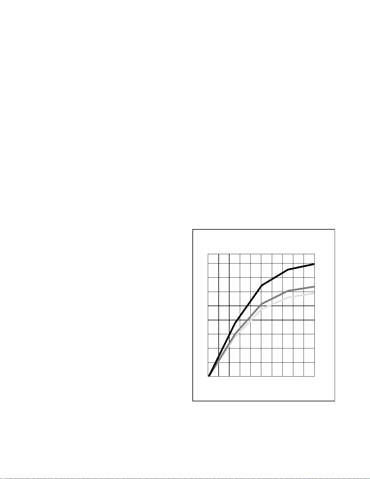
SECTION 4
OPERATION
4.1 INSPECTION (Before Starting)
WARNING
Beware of unannounced starting of the
evaporator and condenser fans. The unit
may cycle the fans and compressor unexpectedly as control requirements dictate.
a. If containeris empty,check inside for the following:
1. Check channels or “T” bar floor for cleanliness.
Channels must be free of debris for proper air circulation.
2. Checkcontainerpanels,insulationanddoorsealsfor
damage. Effect permanent or temporary repairs.
3. Visuallycheckevaporatorfanmotormountingbolts
for proper securement (refer to paragraph 6.17).
4. Checkfordirtorgreaseonevaporatorfan or fandeck
and clean if necessary.
5. Check evaporator coil for cleanliness or obstructions. Wash with fresh water.
6. Check defrostdrain pansand drain lines forobstructions and clear if necessary. Wash with fresh water.
7. Checkpanelsonrefrigerationunitforlooseboltsand
condition of panels. Make sure T.I.R.devices arein
place on access panels.
b. Check condenser coil for cleanliness. Wash with
fresh water.
c. Open control box door. Check for loose electrical
connections or hardware.
d. Checkcolor of moisture-liquid indicator.
e. Check oil level in compressor sight glass.
4.2 CONNECT POWER
WARNING
Do not attemptto removepower plug(s)before turning OFF start-stop switch (ST),
unit circuit breaker(s) and external power
source.
4.3 ADJUST FRESH AIR MAKEUP VENT
The purpose of the fresh air makeup vent is to provide
ventilation for commodities that require fresh air
circulation. The vent must be closed whentransporting
frozen foods.
Air exchange depends on static pressure differential,
whichwillvarydependingon the containerandhowthe
container is loaded.
4.3.1 Upper Fresh Air Makeup Vent
Two slots and a stop are designed into the disc for air
flowadjustments.The firstslot allowsfora0to30%air
flow, and the second slot allows for a 30 to 100% air
flow. To adjust the percentage of air flow, loosen the
wingnut and rotatethediscuntil the desiredpercentage
of air flow matches with the arrow. Tighten the wing
nut. Toclearthe gap between the slots, loosenthe wing
nut until the disc clears the stop. F igure 4-1 gives air
exchangevalues for an empty container. Higher values
can be expected for a fully loaded container.
AIR
FLOW
(CMH)
240
210
180
150
120
90
69NT FRESH AIR M AKEUP
ZERO EXTERNAL STATIC50HZ
For 60HZ operation multiply curves by 1.2
T-BAR
1-!/2”
T-BAR
2-%/8”
T-BAR
3”
WARNING
Makesurethepowerplugs arecleananddry
before connecting to any power receptacle.
4.2.1 Connection To 380/460 vac Power
1. Make sure start-stop switch (ST, on control panel)
and circuit breaker (CB-1, in the control box) are in
position “0” (OFF).
2. Plug the 460 vac (yellow) cable into a de-energized
380/460 vac, 3-phase power source. Energize the
power source. Place circuit breaker (CB-1) in posi-
tion “I” (ON). Close and secure control box door.
4-1
60
30
0
0 102030405060708090100
PERCENT OPEN
Figure 4-1 Make Up Air Flow Chart
T-309
Page 54

4.4 CONNECT REMOTE MONITORING
RECEPTACLE
If remote monitoring is required, connect remote
monitorplugat unitreceptacle.(Seeitem 9,Figure 2-5.)
When the remote monitor plug is connected to the
remote monitoring receptacle, the following remote
circuits are energized:
CIRCUIT FUNCTION
Sockets B to A Energizes remote cool light
Sockets C to A Energizes remote defrost light
Sockets D to A Energizes remote in-range light
1. Depress the ALT MODE key and scroll to Code
dC30.
2. Depress and hold the ENTER key for five seconds.
3. The “Trip Start” event will be entered in the DataCORDER.
4.6.3 Complete Inspection
Allow unit to run for 5 minutes to stabilize conditions
andperform apre--tripdiagnosis inaccordance withthe
following paragraph.
4.7 PRE-TRIP DIAGNOSIS
4.5 STARTING AND STOPPING INSTRUCTIONS
WARNING
Make sure that the unit circuit breaker(s)
(CB-1 & CB-2) and the START-STOP
switch(ST) arein the“O”(OFF)positionbefore connecting to any electrical power
source.
4.5.1 Starting the Unit
1. Withpowerproperlyapplied, the freshair damperset
and (if required) the water cooled condenser connected, (refer to paragraphs 4.2 & 4.3) place the
START-STOP switch to “I” (ON).
NOTE
Withinthe first30seconds the electronicphase
detection system will check for proper compressor rotation. If rotation is not correct, the
compressorwillbe stopped andrestartedin the
oppositedirection.If thecompressorisproducing unusually loud and continuous noise after
the first 30 seconds of operation, stop the unit
and investigate.
2. Continue with Start Up Inspection, paragraph 4.6.
4.5.2 Stopping the Unit
To stop the unit, place the START-STOP switch in
position “0” (OFF).
4.6 START--UP INSPECTION
4.6.1 Physical Inspection
a. Check rotation of condenser and evaporator fans.
b. Check compressoroil level. (Refer to paragraph 6.9.)
4.6.2 Check Controller Function Codes
Checkand, if required, resetcontrollerFunction Codes
(Cd27 through Cd39) in accordance with desired
operating parameters. Refer to paragraph 3.2.2.
DataCORDER
a. Check and, if required, set the DataCORDER Con-
figuration in accordance with desired recording parameter. Refer to paragraph3.6.3.
b. Enter a “Trip Start”. To enter a “trip Start”, do the
following:
CAUTION
Pre-tripinspectionshould not be performed
with critical temperaturecargoes inthe container.
CAUTION
When Pre-Trip keyis pressed, economy, dehumidification and bulb mode will be deactivated.Atthecompletionof Pre-Tripactivity, economy, dehumidification and bulb
mode must be reactivated.
Pre-Trip diagnosis provides automatic testing of the
unit components using internal measurements and
comparisonlogic. The program will provide a “PASS”
or “FAIL” display to indicate test results.
The testing begins with access to a pre-trip selection
menu. The usermay have theoption ofselecting one of
two automatic tests. These tests will automatically
perform a series of individual pre--trip tests. The user
may also scroll down to select any of the individual
tests.Whenonlytheshortsequenceisconfigureditwill
appear as “AUtO” in the display, otherwise “AUtO1”
will indicate the short sequence and “AUtO2” will
indicatethelong sequence.The testshortsequencewill
runtestsP0 throughP6. Thelongtestsequencewillrun
tests P0 through P10.
Adetailed description of the pre-triptestcodes is listed
in Table 3-7, page 3-21. If no selection is made, the
pre-trip menu selection process will terminate
automatically. However, dehumidification and bulb
mode must be reactivatedmanually if required.
Scrolling down to the “rSLts” code and pressing
ENTER will allow the user to scrollthrough theresults
ofthelastpre--triptestingrun.Ifnopre--testinghasbeen
run(oranindividual t est has not beenrun)sincetheunit
was powered up “--------” will be displayed.
To start a pre--trip test, do the following:
NOTE
1. Prior to startingtests,verifythatunitvoltage
(Function Code Cd 07) is within tolerance
and unit amperage draw (Function Codes
Cd04, Cd05, Cd06) are within expected
limits. Otherwise, tests may fail incorrectly.
2. All alarms must be rectified and cleared
before starting tests.
T-309 4-2
Page 55

3. Pre-trip may also be i nitiated via
communications.Theoperationis the same
asforthekey pad initiationdescribedbelow
except that should a test fail, the pre-trip
mode will automatically terminate. When
initiatedviacommunications,atestmaynot
be interrupted with an arrow key, but the
pre-trip mode can be terminated with the
PRE-TRIP key.
a. Press the PRE-TRIP key. This accesses a test selec-
tion menu.
b. TO RUN AN AUTOMATIC TEST: Scroll through
the selections by pressing the UP ARROW or
DOWNARROWkeys to displayAUTO,AUTO1or
AUTO 2 as desired and then press the AUTO key.
1. The unit will execute the series of tests without any
need for direct user interface. These tests vary in
length, depending on the component under test.
2. Whiletestsarerunning,“P#-#”willappearontheleft
display, where the #’s indicate the test number and
sub-test. The right display will show a countdown
time in minutes and seconds, indicating how much
time there is left remaining in the test.
CAUTION
When a failure occurs during automatic
testing the unit will susp end operation
awaiting operator intervention.
Whenanautomatictestfails,itwillberepeatedonce.
Arepeated testfailurewillcause“FAIL”to be shown
ontherightdisplay,withthecorrespondingtestnumber to the left. The user may then press the DOWN
ARROWtorepeatthetest,theUPARROWtoskipto
the next test or the PRE--TRIP key to terminate testing. The unit will wait indefinitely, until the user
manually enters a command.
CAUTION
When Pre--Trip test Auto 2 runs to completionwithoutbeing interrupted,the unit will
terminate pre-trip and display “Auto 2”
“end.”The unit willsuspendoperationuntil
the user depresses the ENTER key!
Whenan Auto 1 runs to completionwithoutafailure,
theunit will exitthepre-tripmode, andreturn to normal control operation. However, dehumidification
and bulb mode must be reactivated manually if required.
c. TO RUN AN INDIVIDUAL TEST : Scroll through
the selections by pressing the UP ARROW or
DOWN ARROW keys to display an individual test
code. Pressing ENTER when the desiredtest codeis
displayed.
1. Individually selected tests, otherthan the LED/Display test, will perform the operations necessary to
verify the operation of the component. At t he conclusion, PASSor FAILwill bedisplayed. Thismessage will remain displayed for up to three minutes,
during which time a user may select another test. If
the three minute time period expires, the unit will
terminate pre-tripand return tocontrol mode operation.
2. While the tests are being executed, theuser may terminatethepre-tripdiagnosticsbypressingandholding the PRE-TRIP key. The unit will then resume
normal operation. If the user decides to terminate a
test but remain at the test selection menu, the user
may press the UP ARROW key. When this is done
all test outputs will be de-energized and the test
selection menu will be displayed.
3. Throughout the duration of any pre-trip test except
the P-7 high pressure switch tests, the current and
pressure limiting processes are active .
d. Pre-Trip Test Results
At the end of the pre-trip test selection menu, the
message “P,” “rSLts” (pre--trip results) will be
displayed.Pressing the ENTER key will allow the user
tosee the resultsfor all subtests(i.e., 1-0, 1-1, etc). The
resultswillbedisplayedas“PASS”or“FAIL”forallthe
testsrun to completion since power up. If a test has not
beenrunsincepowerup, “
-- -- -- -- -- ”willbedisplayed.
Once all pre--test activity is completed,
dehumidification and bulb mode must be reactivated
manually if required.
4.8 OBSERVE UNIT OPERATION
4.8.1 Probe Check
IftheDataCORDERisofforin alarmthecontrollerwill
revertto a four probe configuration which includes the
DataCORDER supply and return air probes as the
secondary controller probes. The controller
continuously performs probe diagnosis testing which
compares the four probes. If the probe diagnosis result
indicates a probe problem exists, the controller will
performa probe check to identify the probe(s) in error.
a. Probe Diagnostic Logic -- Standard
Iftheprobecheckoption(controllerconfigurationcode
CnF31) is configured for standard, the criteria used for
comparisonbetweentheprimaryandsecondarycontrol
probes is:
1_C(1.8_F)forperishableset points or2_C(3.6_F)
for frozen set points.
If25 ormoreof30readingstakenwithina 30minute
periodareoutsideof the limit, thena defrost isinitiated and a probe check is performed.
Inthis configuration, a probecheckwillbe runas a part
of every normal (time initiated) defrost.
b. Probe Diagnostic Logic -- Special
If the probe check option is configured for special the
abovecriteriaareapplicable.Adefrostwithprobecheck
will be initiated if 25 of 30 readings or 10 consecutive
readings are outside of the limits
Inthis configuration, a probe check will not be run asa
part of a normal defrost, but only as a part of a defrost
initiated due to a diagnostic reading outside of the
limits.
c.The30minutetimerwillberesetateachofthefollow-
ing conditions:
4-3
T-309
Page 56

1. At every power up.
2. At the end of every defrost.
3. After every diagnostic check that does not fall outside of the limits as outlined above.
d. Probe Check
A defrost cycle probe check is accomplished by
energizing just the evaporatormotors for eight minutes
at the end of the normal defrost. At the endof the eight
minute period the probes will be compared to a set of
predeterminedlimits. The defrostindicatorwillremain
on throughout this period.
Any probe(s) determined to be outside the limits will
cause the appropriate alarm code(s) to be displayed to
identify which probe(s) needs to be replaced. The P5
Pre-Trip test must be run to inactivate alarms.
4.9 SEQUENCE OF OPERATION
General operation sequences for cooling, heating and
defrost are provided in the following subparagraphs.
Schematic representation of controller action are
providedin
Figure 4-2 and Figure 4-3. RefertoSection3
for detailed descriptions of special events and timers
thatareincorporatedbythe controllerin specificmodes
of operation.
PULL DOWN
START UNLOADED,
TRANSITION TO
ECONOMIZED
OPERATION
UNLOADED OPERATION
AIR CIRCULATION
HEATING
+2.5_C
(4.5_F)
+.20_C
SET POINT
--0.20_C
-- 0 . 5 _C
(0.9_F)
FALLING
TEMPERA TURE
MODULATED
COOLING
UNLOADED
AIR CIRCULATION
HEATING
+2.5_C
(4.5_F)
+.20_C
SET POINT
--0.20_C
-- 0 . 5 _C
(0.9_F)
RISING
TEMPERA TURE
MODULATED
COOLING
UNLOADED
AIR CIRCULATION
HEATING
NOTE: TEMPERATURES INDICATIONS ARE ABOVE OR BELOW SET POINT
Figure 4-2 Controller Operation -- Perishable Mode
T-309 4-4
Page 57

FALLING
TEMPERA TURE
START UNLOADED,
TRANSITION TO
ECONOMIZED
OPERATION
RISING
TEMPERA TURE
COOLING
ECONOMIZED
+.20_C
SET POINT
--0.20_C
AIR CIRCULATION
AIR CIRCULATION
NOTE: TEMPERATURES INDICATIONS ARE ABOVE OR BELOW SET POINT
Figure 4-3 Controller Operation -- Frozen Mode
ENERGIZED
DE--ENERGIZED
FORFULL DIAGRAM AND
LEGEND,SEE SECTION7
POWER TO
CONTROLLER
TD
SIGNAL TO
CONTROLLER
NOTE:HIGH SPEED EVAPORATORFANSHOWN. FOR LOW SPEED
CONTACTTE IS DE--ENERGIZED AND CONTACT TV IS ENERGIZED
CONTROL TRANSFORMER
PB
T6
T6
TS
PA
TU
USV
PA
PB
ESV
Figure 4-4 Perishable Mode
4.9.1 Sequence Of operation -- Compressor Phase
Sequence
The controller logic will check for proper compressor
rotation. If the compressor is rotating in the wrong
direction, the controller will energize or de --energize
relay T6 as required (see Figure 4-4). Energizing relay
T6willswitchoperationfromcompressorcontactorPA
to compressor contactor PB. De--energizing relay T6
will switch operationfrom compressorcontactor PB to
compressorcontactorPA.Compressorcontactors PAis
wired to run the compressor on L1, L2, and L3.
Compressor contactor PB is wired to run the
compressor on L2, L1 and L3 thus providing reverse
rotation .
4.9.2 Sequence Of Operation -- Perishable Mode
Cooling
NOTE
IntheConventional PerishableMode of operationtheevaporatormotorsrun in highspeed.In
theEconomy PerishableMode thefan speed is
varied.
a. With supply air temperature above set point and de-
creasing,the unit will be cooling with the condenser
fanmotor(CF), compressormotor(PAor PB), evaporatorfanmotors(EF)energizedandtheCOOLlight
illuminated. (See Figure 4-4.) Also, if current or
pressurelimiting is not active, the controller will energize relay TS to open the economizer solenoid
valve(ESV) and placethe unitin economizedoperation.
b. When the air temperature decreases to a predeter-
minedtoleranceabove set point, the in-range light is
illuminated.
c. As the air temperature continues to fall, modulating
coolingstarts at approximately2.5_C (4.5_F) above
set point. (See Figure 4-2.) At set point, relay TS is
de--energized to close theeconomizer solenoid valve
and relay TU is energizedto open the unoladersole-
4-5
T-309
Page 58

noid valve changing from economized operation to
unloaded operation. (As shown in Figure 4-5)
d. The controllermonitors the supply air.Oncethesup-
plyairfallsbelowsetpointthecontrollerperiodically
recordsthesupplyairtemperature,setpointandtime.
Acalculationisthenperformedto determinetemperature drift from set point over time.
e. If the calculation determines cooling is no longer re-
quired,contactsTDandTNareopenedtode-energize
compressormotor andcondenserfanmotor.Thecool
light is also de-energized.
f. Theevaporatorfanmotorscontinuetoruntocirculate
air throughout the container. The in-range light remains illuminated as long as the supply air is within
toleranceof set point.
g. If the supply air temperature increases to 0.2_C
(0.4_F) above set point andthe threeminuteofftime
has elapsed, relays TD, TU and TN are energized to
restart the compressor and condenser fan motors in
unloaded operation. The cool light is also illuminated.
ENERGIZED
DE--ENERGIZED
FORFULL DIAGRAM AND
LEGEND,SEE SECTION7
CONTROL TRANSFORMER
rator fans continue to run to circulate air throughout
the container.
c. A safety heater termination thermostat (HTT), at-
tached to an evaporator coil support, will open the
heating circuit if overheating occurs.
4.9.4 Sequence Of operation -- Frozen Mode Cooling
a. With supply air temperature above set point and de-
creasing,theunit will transitionto economizedcooling with the condenser fan motor (CF), compressor
motor (CH), economizer solenoid valve (ESV), low
speed evaporator fan motors (ES) energized and the
COOL light illuminated. (See Figure 4-6.)
b.When the air temperature decreases to a predeter-
minedtoleranceabove set point, the in-range light is
illuminated.
ENERGIZED
DE--ENERGIZED
FORFULL DIAGRAM AND
LEGEND,SEE SECTION7
POWER TO
CONTROLLER
TD
CONTROL TRANSFORMER
PB
T6
T6
PA
PA
PB
POWER TO
CONTROLLER
PB
T6
TD
SIGNAL TO
CONTROLLER
NOTE:HIGH SPEED EVAPORATORFANSHOWN. FOR LOW SPEED
CONTACTTE IS DE--ENERGIZED AND CONTACT TV IS ENERGIZED
T6
TU
TS
PA
USV
PA
PB
ESV
Figure 4-5 Perishable Mode Heating
4.9.3 Sequence Of Operation -Perishable Mode Heating
a. Ifthe air temperaturedecreases 0.5_C(0.9_F) below
set point, the system enters the heating mode. (See
Figure 4-2). The controller closes contacts TH (see
Figure 4-5)to allowpowerflowthrough the heattermination t hermostat (HTT) to energize the heaters
(HR).TheHEATlightisalsoilluminated.Theevaporator fans continue to run to circulate air throughout
the container.
b. When the temperature rises to 0.2_C (0.4_F) above
set point, contact TH opens to de--energize the heaters.The HEAT lightis alsode--energized.Theevapo-
SIGNAL TO
CONTROLLER
TU
USV
TS
ESV
Figure 4-6 Frozen Mode
c. When the return air temperature decreases to 0.2_C
(0.4_F) below setpoint, contactsTD, TS and TN are
opened to de-energize the compressor, economizer
solenoid valve and condenser fan motors. The cool
light is also de-energized.
d. The evaporator fan motors continue to run in low
speed to circulate air throughout the container. The
in-range light remains illuminated as long as the return air is within tolerance of set point.
e. When return air temperatureis 10_C(18_F) ormore
below set point, the evaporator fans are brought to
high speed.
f. When the return air temperature increases to 0.2_C
(0.4_F) above set point andthe threeminuteofftime
has elapsed, relays TD, TS and TN are energizes to
restartthe compressorandcondenserfanmotors.The
cool light is illuminated.
4.9.5 Sequence Of Operation -- Defrost
The defrost cycle may consist of up to three distinct
operations.Thefirst is de-icingofthecoil,the secondis
a probe check cycle and the third is snap freeze.
T-309 4-6
Page 59

Defrost may be initiated by any one of the following
methods:
1. The manual defrost switch (MDS) is closed by the
user.
2. The user sends a defrost command by communica-
tions.
3. The defrost interval timer (controller function code
Cd27) reaches the defrost interval set by the user.
4. The controller probe diagnostic logic determines
thataprobecheckisnecessary basedonthetemperature values currently reported by the supply and return probes.
5. If the controller is programmed with the Demand
Defrostoption (Future) andthe option is set to “IN”
the unit will enterdefrost if it has been in operation
for over 2.5 hours without reaching set point.
ENERGIZED
DE--ENERGIZED
FORFULL DIAGRAM AND
LEGEND,SEE SECTION7
POWER TO
CONTROLLER
TD T6
CONTROL TRANSFORMER
PB
T6
PA
PA
PB
If the controller is programmed with the Lower DTT
setting option the defrost termination thermostat set
pointmaybeconfiguredtothedefaultof 25.6_C(78_F)
orloweredto18_C(64_F).Whenarequestfordefrostis
made by use of the manual defrost switch,
communications or probe check the unit will enter
defrost if the defrost temperature thermostat reading is
at or below the defrost termination thermostat setting.
Defrost will terminate with the defrost temperature
sensor reading rises above the defrost termination
thermostat setting. When a request for defrost is made
bythedefrostintermaletimeror bydemanddefrost,the
defrosttemperaturesetting setting mustbe below 10_C
(50_F).
Whenthe defrost mode is initiatedthe controlleropens
contacts TD, TN and TE (or TV) to de-energize the
compressor, condenser fan and evaporator fans. The
COOL light is also de--energized.
The controller then closes TH to supply power to the
heaters. The defrost light is illuminated.
Whenthedefrost temperaturesensorreadingrises tothe
defrost termination thermostat setting, the de--i cing
operation i s terminated.
If defrost does not terminate correctly and temperature
reaches the set point of theheat termination thermostat
(HTT) the thermostat will open to de--energize the
heaters.If termination does not occurwithin 2.0 hours,
the controller will terminate defrost. An alarm will be
given of a possible DTS failure.
SIGNAL TO
CONTROLLER
TU
USV
TS
ESV
Figure 4-7 Defrost
Defrost may be initiated any time the defrost
temperature sensor reading falls below the controller
defrost termination thermostat set point. Defrost will
terminate when the defrost temperature sensor reading
risesabovethedefrostterminationthermostat set point.
The defrost termination thermostat is not a physical
component. It is a controller setting that acts as a
thermostat, “closing” (allowing defrost) when the
defrosttemperaturesensorreadingisbelowthesetpoint
and“opening”(terminatingorpreventingdefrost)when
thesensortemperaturereadingis aboveset point. When
the unit is operating in bulb mode (refer to paragraph
3.3.9), special settings may be applicable.
If probe check (controller function code CnF31) is
configured to special, the unit will proceed to the next
operation (snapfreeze or terminatedefrost).If thecode
is configuredto standard, the unit will perform a probe
check. The purpose of the probe check is to detect
malfunctions or drift in the sensed temperature that is
too small to be detected by the normal sensor out of
rangetests. Thesystemwillrunforeightminutesinthis
condition.Attheend ofthe eight minutes, probealarms
will be set or cleared based on the conditions seen.
When the return air falls to 7_C(45_F), the controller
checks to ensure the defrost temperature sensor (DTS)
reading has dropped to 10_C or below. If it has not, a
DTS failure alarm is given and the defrost mode is
operated by the return temperature sensor (RTS).
Ifcontrollerfunction codeCnF33 is configured tosnap
freeze, the controller will sequence to this operation.
The snap freeze consists of running the compressor
without the evaporatorfans in operation for a periodof
four minutes with the suction modulation valve fully
open. When the snap freeze is completed, defrost is
formally terminated.
4-7
T-309
Page 60

SECTION 5
Nopowertounit
L
Component(s)NotOperatin
g
Compressorhum
s,butdoesno
t
TROUBLESHOOTING
CONDITION POSSIBLE CAUSE
5.1 UNIT WILL NOT START OR STARTS THEN STOPS
External power source OFF Turn on
No power to unit
oss of control power
Component(s) Not Operating
Compressor hums,but does not
start
Start-Stop switch OFF or defective Check
Circuit breaker tripped or OFF Check
Circuit breaker OFF or defective Check
Control transformer defective Replace
Fuse (F3) blown Check
Start-Stop switch OFF or defective Check
Evaporator fan motor internal protector open 6.17
Condenser fan motor internal protector open 6.12
Compressor internal protector open 6.8
High pressure switch open 5.7
Heat termination t hermostat open Replace
Loss of communication with expansion module Check Wiring
Malfunction of current sensor Replace
Low line voltage Check
Single phasing Check
Shorted or grounded motor windings 6.8
Compressor seized 6.8
REMEDY/
REFERENCE
SECTION
5.2 UNIT OPERATES LONG OR CONTINUOUSLY IN COOLING
Hot load Normal
Container
Defectivebox insulation or air leak Repair
Shortage of refrigerant 6.7.1
Evaporator coil covered with ice 5.6
Evaporator coil plugged with debris 6.15
Evaporator fan(s) rotating backwards 6.15/6.17
Defective evaporator fan motor/capacitor 6.18
Air bypass around evaporator coil Check
Controller set too low Reset
Refrigeration System
Compressor service valves or liquid line shutoff valve partially closed
Dirty condenser 6.11
Compressor worn 6.8
Current limit (function code Cd32) set to wrong value 3.5.5
Suction modulation valve lost track of step count Powercycle
Suction modulation valve malfunction 6.20
Economizer solenoid valve or TXV malfunction 6.14, 6.19
Unloader valve stuck open 6.19
Open valves
completely
5-1
T-309
Page 61

CONDITION POSSIBLE CAUSE
Nooperationofanykin
d
Nocontrolpowe
r
Unitwillnotheatorhasinsuffi
-
Unitfailstostopheatin
g
Willnotinitiatedefros
t
5.3 UNIT RUNS BUT HAS INSUFFICIENT COOLING
Abnormal pressures 5.7
Abnormal temperatures 5.15
Abnormal currents 5.16
Controller malfunction 5.9
Evaporator fan or motor defective 6.17
Shortage of refrigerant 6.7.1
Refrigeration System
Suction modulation valve lost track of step count Powercycle
Suction modulation valve malfunction 6.20
Compressor service valves or liquid line shutoff valve par-
tially closed
Economizer solenoid valve or TXV malfunction 6.14, 6.19
Unloader valve stuck open 6.19
Frost on coil 5.10
5.4 UNIT WILL NOT HEAT OR HAS INSUFFICIENT HEATING
Start-Stop switch OFF or defective Check
No operation of any kind
Circuit breaker OFF or defective Check
External power source OFF Turn ON
Circuit breaker or fuse defective Replace
Control Transformer defective Replace
No control power
Evaporator fan internal motor protector open 6.17
Heat relay defective Check
Heater termination thermostat open 6.15
Heater(s) defective 6.15
Heater contactor or coil defective Replace
Evaporator fan motor(s) defective or rotating backwards 6.15/6.17
Unitwill not heat or has i nsufficient heat
Evaporator fan motor contactor defective Replace
Controller malfunction 5.9
Defectivewiring Replace
Loose terminal connections Tighten
Low line voltage 2.3
REMEDY/
REFERENCE
SECTION
Open valves
completely
5.5 UNIT WILL NOT TERMINATE HEATING
Controller improperly set Reset
Controller malfunction 5.9
Heater termination thermostat remains closed along with
the heat relay
5.6 UNIT WILL NOT DEFROST PROPERLY
6.15
Defrost timer malfunction (Cd27) Table 3-5
Loose terminal connections Tighten/
Willnot initiate defrost
automatically
Defectivewiring Replace
Defrost temperature sensor defective or heat termination
thermostat open
Replace
Heater contactor or coil defective Replace
5-2T -309
Page 62

CONDITION POSSIBLE CAUSE
Willnotinitiatedefros
t
Lowsuctionpressur
e
l
izew
h
Compresso
r
CondenserorEvaporatorFa
n
5.6 UNIT WILL NOT DEFROST PROPERLY -- Continued
REMEDY/
REFERENCE
SECTION
Willnot initiate defrost
manually
Initiates but relay (DR) drops
out
Manual defrost switch defective Replace
Defrost temperature sensor open 4.9.5
Low line voltage 2.3
Heater contactor or coil defective Replace
Initiates but does not defrost
Heater(s) burned out 6.15
Frequent defrost Wet load Normal
5.7 ABNORMAL PRESSURES (COOLING)
Condenser coil dirty 6.11
Condenser fan rotating backwards 6.12
Condenser fan inoperative 6.12
High discharge pressure
Refrigerant overcharge or noncondensibles 6.7.1
Discharge service valve partially closed Open
Suction modulation valve malfunction 6.20
Faulty suction pressure transducer Replace
Suction service valve partially closed Open
Filter-drier partially plugged 6.13
Low refrigerant charge 6.7.1
Low suction pressure
Expansion valve defective 6.14
No evaporator air flow or restricted air flow 6.15
Excessive frost on evaporator coil 5.6
Evaporator fan(s) rotating backwards 2.3
Suction modulation valve malfunction 6.20
Suction and discharge pressures
tendto equa
en unitis
operating
Compressor operating in reverse 5.14
Compressor cycling/stopped Check
5.8 ABNORMAL NOISE OR VIBRATIONS
Compressor start up after an extended shutdown
Brief chattering when manually shut down
Compressor operating in reverse 5.14
Compressor
Loose mounting bolts or worn resilient mounts Tighten/Replace
Loose upper mounting 6.8.1 step r.
Liquid slugging 6.14
Insufficient oil 6.9
Bent, loose or striking venturi Check
Condenser or Evaporator Fan
Worn motor bearings 6.12/6.17
Bent motor shaft 6.12/6.17
5-3
Normal
T-309
Page 63

CONDITION POSSIBLE CAUSE
Willnotcontro
l
w
w
t
5.9 CONTROLLER MALFUNCTION
Defective Sensor 6.22
Defectivewiring Check
Willnot control
Fuse (F1, F2, F3) blown Replace
Stepper motor suction modulation valve circuit malfunction 6.20
Low refrigerant charge 6.7
5.10 NO EVAPORA T OR AIR FLOW OR RESTRICTED AIR FLOW
REMEDY/
REFERENCE
SECTION
Evaporator coil blocked
Dirty coil 6.15
Evaporator fan motor internal protector open 6.17
Evaporator fan motor(s) defective 6.17
Frost on coil 5.6
No or partial evaporator air flo
Evaporator fan(s) loose or defective 6.17
Evaporator fan contactor defective Replace
5.11 THERMOSTATIC EXPANSION VALVE MALFUNCTION
Low refrigerant charge 6.7.1
External equalizerline plugged Open
Wax, oil or dirt plugging valve or orifice Ice formation at
valve seat
Low suction pressure with high
superheat
Superheat not correct 6.7.1
Power assembly failure
Loss of element/bulb charge
Broken capillary
Foreign material in valve
Superheat setting too low 6.14
High suction pressurewith lo
superhea
External equalizerline plugged Ice holding valve open Open
Foreign material in valve 6.14
Liquid slugging in compressor
Pin and seat of expansion valve eroded or held open by for-
eign material
Improper bulb location or installation
Fluctuating suction pressure
Low superheat setting
6.14
6.14
6.14
5.12 AUTOTRANSFORMER MALFUNCTION
Circuit breaker (CB-1 or CB-2) tripped Check
Unitwill not start
5.13 WATER-COOLED CONDENSER OR WATER PRESSURE SWITCH
Power source not turned ON Check
Waterpressure switch malfunction Check
Condenser fan starts and stops
Watersupply interruption Check
5-4T -309
Page 64

CONDITION POSSIBLE CAUSE
Electrica
l
Check
Highdischargetemperatur
e
Low
5.14 COMPRESSOR OPERATING IN REVERSE
REFERENCE
CAUTION
Allowingthescrollcompressortooperatein reversefor morethan two minuteswill resultin internal
compressor damage. Turn the start--stop switch OFF immediately .
Incorrect wiring of compressor
Electrical
Incorrect wiring of compressor contactor(s)
Check
Incorrect wiring of current sensor
5.15 ABNORMAL TEMPERATURES
Dischargetemperature sensor drifting high Replace
Failed economizer, TXV or solenoid valve Replace
High discharge temperature
Plugged economizer,TXV or solenoid valve Replace
Loose or insufficiently clamped sensor Replace
Failed liquid injection solenoid valve Replace
Dischargetemperature sensor drifting low Replace
suction temperature
5.16 ABNORMAL CURRENTS
Loose or insufficiently clamped sensor Replace
REMEDY/
SECTION
Unit reads abnormal currents Current sensor wiring Check
5-5
T-309
Page 65
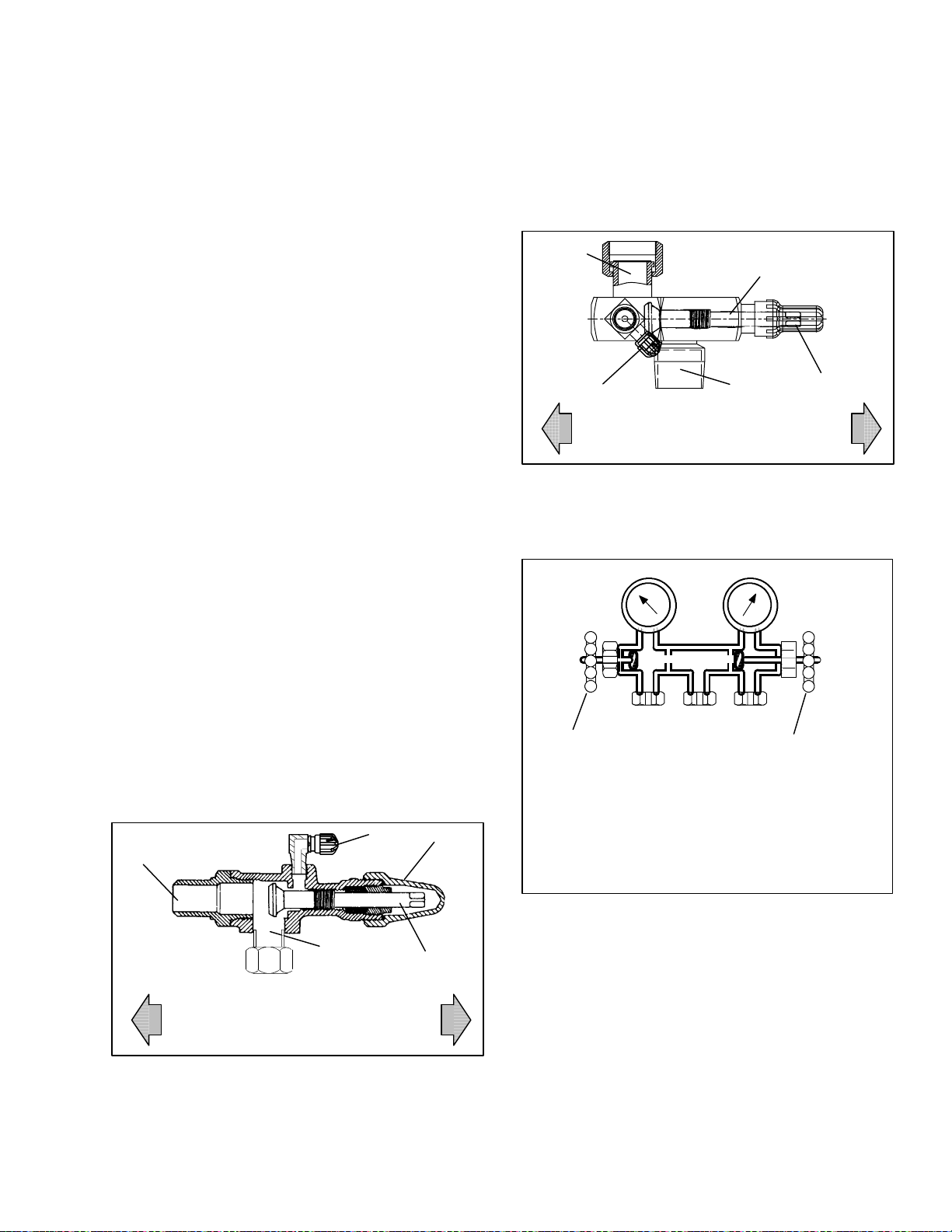
SECTION 6
SERVICE
NOTE
Toavoiddamageto theearth’sozonelayer,usearefrigerantrecoverysystemwheneverremovingrefrigerant.
When working with refrigerants you must comply with all local government environmental laws. In the
U.S.A., refer to EPA section 608.
WARNING
Neveruseair for leak testing.Ithas beendetermined that pressurized, mixtures of refrigerant and air can undergo combustion
when exposed to an ignition source.
6.1 SECTION LAYOUT
Serviceprocedures are provided herein beginning with
refrigeration system service, then refrigeration system
component service, electrical system service,
temperature recorder serviceand general service. Refer
to the TableOf Contents to locate specific topics.
6.2 SERVICE VALVES
The compressor suction, compressor discharge,
compressor economizer, oil return and the liquid line
service valves (see Figure 6-1) are provided with a
double seat and an access valve which enable servicing
of the compressor and refrigerant lines. Turning the
valve stem clockwise (all the way forward) will
frontseat the valve to close off the line connection and
open a path to the access valve. Turning the stem
counterclockwise (all the way out) will backseat the
valveto open the line connection and close offthe path
to the access valve.
With the valve stem midway between frontseat and
backseat,both of the servicevalveconnectionsareopen
to the access valve path.
For example, the valve stem is first fully backseated
whenconnectingamanifoldgaugetomeasurepressure.
Then,the valveis opened1/4 to 1/2 turnto measurethe
pressure.
2
1
3
5
2
VALVE
FRONTSEATED
(Clockwise)
1. Line Connection
2. Access Valve
3. Stem Cap
Figure 6-2 Suction Service Valve
SUCTION
PRESSURE
GAUGE
A
OPENED (Backseated )
HAND VALVE
A. CONNECTION TO LOW SIDE OF SYSTEM
B. CONNECTION TO EITHER:
REFRIGERANT CYLINDER OR
OIL CONTAINER
C. CONNECTION TO HIGH SIDE OF SYSTEM
VALVE
BACKSEATED
(Counterclockwise)
4. Valve stem
5. Compressor Inlet
BC
4
1
Connection
DISCHARGE
PRESSURE
GAUGE
CLOSED (Frontseated)
HAND VALVE
3
VALVE
FRONTSEATED
(Clockwise)
1. Line Connection
2. Access Valve
3. Stem Cap
Figure 6-1 Service Valve
5
VALVE
BACKSEATED
(Counterclockwise)
4. Valve stem
5. Compressor Or Filter
Drier Inlet Connection
4
Figure 6-3 Manifold Gauge Set
6.3. MANIFOLD GAUGE SET
The manifold gauge set (see Figure 6-3) is used to
determine system operating pressure, add refrigerant
charge, and to equalize or evacuate the system.
When the suction pressure hand valve is frontseated
(turnedall the wayin),thesuction(low)pressurecanbe
checked. When the discharge pressure hand valve is
frontseated, the discharge (high) pressure can be
checked. When both valves are open (turned
counter-clockwiseallthe way out),high pressurevapor
will flow into the low side. When the suction pressure
valveis open and the dischargepressurevalveshut, the
6-1
T-309
Page 66

system can be charged. Oil can also be added to the
system.
A R-134a manifold gauge/hose set with self-sealing
hoses (see Figure 6-4) is required for service of the
models covered within this manual. The manifold
gauge/hose set is available from Carrier Transicold.
(Carrier Transicold P/N 07-00294-00, which includes
items1through6,Figure 6-4.)Toperformserviceusing
the manifold gage/hose set, do the following:
2. Connect the field service coupling (see Figure 6-4)
to the access valve.
3. Turn the field service coupling knob clockwise,
which will open the system to the gauge set.
4. To read system pressures: slightly midseat the service valve.
5. Repeat the proceduretoconnecttheothersideofthe
gauge set.
a. Preparing Manifold Gauge/Hose Set For Use
1. Ifthemanifoldgauge/hosesetisneworwasexposed
to the atmosphere it will need to be evacuated to
remove contaminants and air as follows:
2. Back seat (turncounterclockwise)bothfieldservice
couplings (see Figure 6-4) and midseat both hand
valves.
3. Connect the yellow hose to a vacuum pump and refrigerant 134a cylinder.
SUCTION
PRESSURE
GAUGE
OPENED
(Backseated )
HAND VALVE
To Low Side
Access Valve
3
BLUE
6
Blue Knob
1. Manifold Gauge Set
2. Hose Fitting (0.5-16 Acme)
3. Refrigeration and/or Evacuation Hose
. (SAE J2196/R-134a)
4. Hose Fitting w/O-ring (M14 x 1.5)
5. High Side Field Service Coupling
6. Low Side Field Service Coupling
Figure 6-4 R-134a Manifold Gauge/Hose Set
4
1
2
3
YELLOW
2
DISCHARGE
PRESSURE
GAUGE
(Frontseated)
HAND VAL VE
To High Side
Access Valve
3
RED
4
CLOSED
5
Red Knob
7. Evacuate to 10 inches of vacuum and then charge
withR-134ato aslightlypositivepressureof0.1kg/
cm@ (1.0 psig).
8. Front seat both manifold gauge set valves and disconnect from cylinder. The gauge set is now ready
for use.
b. Connecting Manifold Gauge/Hose Set
To connect the manifold gauge/hose set for reading
pressures, do the following:
1. Remove service valve stem cap and check to make
sure it is backseated.Remove access valvecap.
Figure 6-1)
(See
CAUTION
Toprevent trapping liquid refrigerantinthe
manifold gauge set be sure set is brought to
suction pressure before disconnecting.
c. Removing the Manifold Gauge Set
1. While the compressor is still ON, backseatthe high
side service valve.
2. Midseat bothhand valveson themanifold gauge set
and allow the pressure in the manifold gauge set to
bedrawndowntolowsidepressure.Thisreturnsany
liquidthatmaybeinthehighsidehosetothesystem.
3. Backseat the low side service valve. Backseat both
field service couplings and frontseat both manifold
set valves. Remove the couplings from the access
valves.
4. Install both servicevalvestem capsand serviceport
caps (finger-tight only).
6.4 PUMPING THE UNIT DOWN
To service the filter-drier, economizer, expansion
valves, moisture-liquid indicator, suction modulation
valve, economizer solenoid valve, unloader solenoid
valve or evaporator coil, pump the refrigerant into the
high side as follows:
CAUTION
The scroll compressor achieves low suction
pressure very quickly. Do not operate the
compressor in a deepvacuum,internaldamage will result.
a. Attach manifoldgauge setto the compressorsuction
and discharge service valves. Referto paragraph 6.3.
b. Start the unit and run in the frozenmode (controller
set below --10°C)for10to15minutes.
c. Check functioncodeCd21 (refertoparagraph3.2.2).
The economizer solenoid valve should be open. If
not, continue to run until the valve opens.
d. Frontseat the oil return service valve then, frontseat
theliquidlineservicevalve.Placestart-stopswitchin
theOFFposition whenthe suctionreaches apositive
pressure of 0.1 kg/cm@ (1.0 psig).
e. Frontseat the economizer service valve and then
frontseat the suction and discharge service valves.
Therefrigerantwillbetrappedbetweenthecompressor suction service valve and the liquid line valve.
f. Before opening up any part of the system, a slight
positivepressure should be indicatedon thepressure
6-2T -309
Page 67

gauge. If a vacuum is indicated, emit refrigerant by
crackingtheliquidlinevalvemomentarilytobuildup
a slight positive pressure.
g. Whenopeningupthe refrigerantsystem, certainparts
mayfrost.Allowthe parttowarmtoambienttemperature before dismantling. This avoids internal condensation which puts moisture in the system.
h. After repairs have been made, be sure to perform a
refrigerant leak check (refer to paragraph 6.5), and
evacuate and dehydrate the low side (refer to paragraph 6.6).
i. Check refrigerant charge (refer to paragraph 6.7).
6.5 REFRIGERANT LEAK CHECKING
WARNING
Never use air for leak testing. It has been
determined that pressurized, air-rich mixtures of refrigerants and air can undergo
combustion when exposed to an ignition
source.
a. The recommended procedure for finding leaks in a
systemiswithaR-134aelectronicleakdetector.Testingjointswithsoapsudsissatisfactoryonlyforlocating large leaks.
b. If thesystemiswithoutrefrigerant,chargethesystem
with refrigerant 134a to build up pressure between
2.1to 3.5 kg/cm@(30to50 psig).Toensurecomplete
pressurization of the system, refrigerant should be
charged at the compressor suction and economizer
servicevalvesandtheliquid line servicevalve.Also,
the area between the suction modulating valve and
evaporatorexpansionvalvemaynot be open to these
chargingpoints. Pressurebetween these components
maybechecked at thelow sideaccess valve(item 11,
Figure 2-2) or by checking that the suction modulating valve is more than 10% open at controller function code Cd01. The suction modulating valve may
beopenedbyuseofthecontrollerfunctioncodeCd41
valve override control (refer to paragraph 6.19). Removerefrigerantcylinder and leak-checkallconnections.
6.6 EVACUATION AND DEHYDRATION
6.6.1 General
Moisture is the deadly enemy of refrigerationsystems.
The presence of moisture in a refrigerationsystem can
have many undesirable effects. The most common are
copper plating,acid sludge formation,“freezing-up” of
meteringdevicesby freewater,and formation of acids,
resulting in metal corrosion.
6.6.2 Preparation
a. Evacuate and dehydrate only afterpressure leaktest.
(Refer to paragraph 6.5.)
b. Essential tools to properly evacuate and dehydrate
anysystem include avacuum pump(8 m
3
/hr= 5cfm
volume displacement) and an electronic vacuum
gauge. (The pump is available from Carrier Transicold, P/N 07-00176-11.)
c. If possible, keep the ambient temperature above
15.6_C(60_F) to speed evaporation of moisture. If
the ambient temperature is lower than 15.6_C
(60_F), ice might form before moisture removal is
complete.Heatlampsoralternatesourcesofheatmay
be used to raise the system temperature.
d. Additional timemaybesavedduringacompletesys-
tem pump down by replaceing the filter-drier with a
sectionof coppertubing and the appropriatefittings.
Installation of a new drier may be performedduring
the charging procedure.
1
11
2
D
S
9
10
3
4
5
6
7
8
NOTE
Only refrigerant 134a should be used to pressurize the system. Any other gas or vapor will
contaminate the system, which will require
additional purging and evacuation of the system.
c. If required, remove refrigerant using a refrigerant
recovery system and repair any leaks.
d. Evacuate and dehydrate theunit. (Referto paragraph
6.6.)
e. Charge unit per paragraph 6.7.
1. Liquid Service Valve
2. Receiver or Water
Cooled Condenser
3. Compressor
4. Discharge Service
Valve
5. Economizer Service
Valve
Figure 6-5. Refrigeration System Service
Connections
6.6.3 Procedure - Complete system
6-3
10. Refrigerant Cylinder
1 1. Reclaimer
6. Suction Service Valve
7. Vacuum Pump
8. Electronic Vacuum
Gauge
9. Manifold Gauge Set
T-309
Page 68

a. Remove all refrigerant using a refrigerant recovery
system.
b. The recommendedmethodtoevacuateanddehydrate
the system isto connectevacuationhosesatthe compressor suction, compressor economizer and liquid
line service valve (see F igure 6-5). Be sure the service hoses are suited for evacuation purposes.
c. The area between the suction modulating valve and
evaporator expansion valve may not be open to the
access valves. To ensure evacuation of this area,
checkthat the suction modulatingvalveis morethan
10% open at controller function code Cd01. If required, the suction modulating valve may be opened
by use of the controller function code Cd41 valve
overridecontrol.Ifpoweris not availabletoopen the
valve, the area may be evacuated by connecting an
additional hoseat the lowside access valve (item 11,
Figure 2-2).
d. Testtheevacuationsetupfor leaksbybackseatingthe
unit service valves and drawing a deep vacuum with
thevacuumpumpandgaugevalvesopen.Shut offthe
pump and check to see if the vacuum holds. Repair
leaks if necessary.
e. Midseat the refrigerant system service valves.
f. Openthevacuumpumpandelectronicvacuumgauge
valves,if they arenotalreadyopen. Start the vacuum
pump. Evacuate unit until the electronic vacuum
gauge indicates 2000 microns. Close the electronic
vacuumgaugeand vacuumpump valves. Shut offthe
vacuumpump.Waitafewminutestobesurethevac-
uum holds.
g. Break the vacuum with clean dry refrigerant 134a
gas. Raise system pressure to approximately 0.2 kg/
cm@ (2 psig), monitoring it with the compound
gauge.
h. Removerefrigerant using a refrigerant recoverysys-
tem.
i. Repeat steps f.and g. one time.
j. Removethecoppertubing and changethefilter-drier.
Evacuate unit to 500 microns. Close the electronic
vacuumgaugeand vacuumpump valves. Shut offthe
vacuum pump. Wait five minutes to see if vacuum
holds. This procedure checks for residual moisture
and/or leaks.
k. With a vacuumstill inthe unit, the refrigerantcharge
may be drawn intothe system from arefrigerant con-
tainer on weight scales. Continue to paragraph 6.7
1
10
DS
9
1. Receiver or Water
Cooled Condenser
2. Compressor
3. Discharge Service
Valve
4. Economizer Service
Valve
Figure 6-6. Compressor Service Connections
6.6.4 Procedure - Partial System
2
8
7
5. Suction Service Valve
6. Vacuum Pump
7. Electronic Vacuum
Gauge
8. Manifold Gauge Set
9. Refrigerant Cylinder
10. Reclaimer
3
4
5
6
a. If the refrigerant charge has been removed from the
compressorforservice,evacuateonlythecompressor
by connecting the evacuation set--upat thecompressor servicevalves. (SeeFigure 6-6.) Follow evacuation procedures of the preceding paragraph except
leave compressor service valves frontseated until
evacuation is completed.
b. If refrigerantcharge has been removed from the low
side only, evacuate the low side by connecting the
evacuation set--up at the compressor suction and
economizer service valves and the liquid service
valveexceptleavethe servicevalvesfrontseateduntil
evacuation is completed.
c. Once evacuation has been completed and the pump
has been isolated, fullybackseatthe service valves to
isolate the service connections and then continue
with checking and, if required, adding refrigerant in
accordance with normal procedures
6-4T -309
Page 69

6.7 REFRIGERANT CHARGE
6.7.1 Checking the Refrigerant Charge
e. Start unit in cooling mode. Run approximately 10
minutes and check the refrigerant charge.
6.7.3 Adding Refrigerant to System (Partial
Charge)
NOTE
Toavoiddamageto the earth’sozone layer,use
arefrigerant recoverysystemwhenever removing refrigerant. When working with refrigerants you must comply with all l ocal government environmental laws. In the U.S. A., refer
to EPAsection 608.
a. Connect the gauge manifold to the compressor dis-
chargeandsuctionservicevalves.Forunitsoperating
on a water cooled condenser, change over to air
cooled operation.
b. Bring the container temperature to approximately
1.7_C(35_F)or--17.8_C(0_F). Thensetthecontrol-
lerset point to --25_C(--13_F) to ensurethat the suc-
tion modulation valve is fully open. (Position of the
suctionmodulatingvalvemay be checkedatcontroller function code Cd01.)
c. Partially block the condenser coil inlet air. Increase
theareablockeduntilthe compressordischargepressureisraisedtoapproximately12kg/cm@(175psig).
d. Onunitsequipped withareceiver,the levelshouldbe
betweenthe glasses. On units equipped with a water
cooledcondenser,the level should beat the center of
theglass.Iftherefrigerantlevelisnot correct,continuewiththefollowing paragraphstoaddorremoverefrigerant as required.
a. Examine the unit refrigerant systemfor any evidence
of leaks. Repair as necessary. (Refer to paragraph
6.5.)
b. Maintain the conditions outlined in paragraph 6.7.1
c. Fully backseat the suction servicevalve and remove
the service port cap.
d. Connect charginglinebetween suction servicevalve
port and cylinder of refrigerant R-134a. Open
VAPOR valve.
e. Partially frontseat (turn clockwise) the suction ser-
vicevalveandslowly add chargeuntil therefrigerant
appearsattheproperlevel. Be carefulnottofrontseat
the suction valve fully,if the compressor is operated
in a vacuum internal damage may result.
6.8 COMPRESSOR -- Model RSH105
WARNING
Make sure power to the unit is OFF and
power plug disconnected before replacing
the compressor.
WARNING
Beforedisassembly of the compressormake
sure to relieve the internal pressure very
carefullyby slightly loosening the couplings
to break the seal.
6.7.2 Adding Refrigerant to System (Full Charge)
a. Evacuate unit and leave in deep vacuum. (Refer to
paragraph 6.6.)
b. Placecylinder of R-134aon scale and connectcharg-
ing line from cylinder to liquid line valve. Purge
charginglineatliquidlinevalveandthennoteweight
of cylinder and refrigerant.
c. Open liquidvalveoncylinder.Open liquid linevalve
half-wayandallow theliquid refrigerantto flowinto
theunituntilthecorrectweightofrefrigerant(referto
paragraph
2.2) has been added as indicated byscales.
NOTE
It may be necessary to finish charging unit
through suction service valve in gas form, due
to pressure rise in high side of the system.
(Refer to section paragraph 6.7.3)
d. Backseatmanualliquid line valve(toclose offgauge
port). Close liquid valve on cylinder.
CAUTION
The scroll compressor achieves low suction
pressure very quickly. Do not use the compressor to evacuate the system below zero
psig. Neveroperate thecompressor with the
suction or discharge service valves closed
(frontseated). Internal damage will result
from operating the compressor in a deep
vacuum.
6.8.1 Removal and Replacement of Compressor
NOTE
Servicecompressorcontains anitrogencharge.
Due to the hygroscopic nature of the oil, time
the compressor is left open to the atmosphere
should be minimized as much as possible.
a. Procure areplacementcompressor kit.A listof items
contained in the compressor kit is provided in
Table 6-1.
b. If thecompressoris operational, pumpthe unitdown
(refer to paragraph 6.4).
6-5
T-309
Page 70

Table 6-1 Compressor Kit
Item
Component Qty
1 Compressor 1
2 Service Valve Seal 3
3 Mylar Washers 4
4 Wire Tie 2
5 Oil Sight Glass Plug 1
6 Resilient Mount 4
7 Upper Shock Mount Ring 1
8 Upper Shock Mount Bushing 1
9 Compressor Power Plug O--Ring 1
10 SST Washers 8
c. If the compressor is not operational, turn the unit
start--stop switch (ST) and unit circuit breaker
(CB--1)OFF.Disconnectpowertotheunitandfront-seatthedischarge,suction,economizer,andoilreturn
service valves.
Remove all remaining refrigerantfrom the compressor using a refrigerant recovery system. Connect
hoses to suction, economizer and discharge service
valves ports. Evacuate compressor to 500 microns
(75.9 cm Hg vacuum = 29.9 inches Hg vacuum).
d. Make sure power to the unit is OFF and unit power
plug disconnected. Disconnect the power plug from
the compressor.
e. Loosenandbreakthesealatfittings from thesuction,
discharge, economizer, and the oil return service
valves. Remove fittings and discard service valve
seals, retain oil return valve O--ring.
f. Remove the entire compressor upper mounting
bracket assembly,(see Figure 6-7) by removing the
fourcapscrewsattachingittotheunitandthe32--mm
bolt from the compressor m ounting bracket.
Upper Shock Mount
Bushing(KitItem8)
32mm Bolt
Figure 6-7 Compressor Upper Mounting
Upper Shock Mount
Ring (Kit Item 7)
Shoulder Bolt
SST Washer
(Kit Item 10)
Resilient Mount
(Kit Item 6)
SST Washer
(Kit Item 10)
Mylar Washer
(Kit Item 3)
Mylar Protector
(Retain)
Base Plate
(Retain)
Mylar Protector
(Retain)
Figure 6-8 Compressor Lower Mounting
g. Replace the upper mounting bracket shock mount
ring and bushing (kit items 7and 8). Reassemblethe
bracketinthesame manneras theoriginal and torque
the shoulder bolt to 2.8 mkg (20 ft--lbs.).
h. Remove the male coupling from the top of the sight
glassontheoldcompressorandhandassembletothe
oil return valve coupling for safe keeping. Plug the
top of the replacement compressor sight glass with
the plug (kit item 5) to prevent spilling oil.
i. Remove the lowermounting bolts and hardware(see
Figure 6-8). Using plugs from replacementcompressor,plug connectionsonoldcompressor.Removethe
old compressor. Refer to paragraph 2.2for compressor weight. Return plugsto replacementcompressor .
j. The replacement compressor is shipped with an oil
chargeof591ml (20 ounces). Before sliding the new
compressorintheunit, removetheoilsightglassplug
and (using a small funnel) charge the compressor
with an additional 1893ml (64 ounces) Castrol--IcematicSW20(POEoil).Reassembletheoilsightglass
plugtoavoidspillingoilwhenslidingthecompressor
in the unit.
k. Securethebaseplateandmylarprotectorstothecom-
pressorwithwireties(kititem 4), andplacethecompressor in the unit.
l. Cut and remove the wire ties that were used to hold
the base plate and protectors to the compressor. Using new resilient mounts, SST washers and mylar
washers(kititems3, 6& 10).Installthe fourmounting screws loosely.
m.Installthemalecoupling(removedinsteph.)intothe
sight glass port.
6-6T -309
Page 71

n. Place the new service seals (kit item 2) at the com-
pressorserviceports, connectthe four service valves
loosely.
o. Torquethefourresilientmountscrewsto6.2mkg(45
ft--lbs).
p. Torque the four service valves to:
Service Valve Torque
Suction or Discharge 11 to 13.8 mkg
(80 to 100 ft--lbs.)
Economizer 6.9to8.3mkg
(50to60ft--lbs.)
Oil Return 1.4to1.66mkg
(10to12ft--lbs.)
q. Reassemble the top mounting bracket (see
Figure 6-7) by hand tightening the 32--mm (1¼
--inch) bolt andtorquingthe fourmounting screwsto
0.9 mkg (6.5 ft--lbs). Align the mounting so that the
ringandbushing assemblyarefreewithnocompression.
r. Torquethe32mm bolt to 1. 5 mkg (11ft--lbs.).While
maintaining the free movement of the shock mount,
torque the four mounting screws to 0.9 mkg (6.5 ft-lbs.).
s. Replace the power plug O--Ring with new ring (kit
item9).Insertthe powerplugintothecompressorfitting. Be sure plug is fully seated into the fitting and
then thread the coupling nut a minimum of 5 turns.
t. Leakcheckandevacuatethe compressorto 1000 mi-
crons. Refer to paragraphs
6.5 and 6.6
u. Runthe unit for at least 15 minutes and check the oil
and refrigerant levels. Refer to paragraphs 6.7 and
6.9.
5 TurnStart/Stopswitch offandallowoilto draininto
compressor sump. Oil level must be visible in the
sightglass.Ifitisnotvisible,oilmustbeaddedtothe
compressor.
b. Adding Oil with Compressor in System
1. The recommendedmethod is to add oil using an oil
pump at the oil return service valve (see item
Figure 2-3
)
15,
2. In anemergencywhereanoil pumpis not available,
oilmaybedrawnintothecompressorthrough theoil
return service valve.
Connect the suction connection of t he gauge manifold to the compressor oil return valve port, and
immersethe common connectionofthe gaugemanifold in an open container of refrigeration oil.
Extreme care must be taken to ensure the manifold
common connection remains immersed in oil at all
times.Otherwiseairandmoisturewillbedrawninto
the compressor. Crack the oil return service valve
andgaugevalvetoventasmallamountofrefrigerant
throughthecommon connectionandtheoil to purge
the lines of air. Close the gauge manifold valve.
Withtheunit running,turn thesuction servicevalve
toward frontseat and induce a vacuum in the compressor crankcase. Do not allow the compressor to
pull below 127mm/hg (5 “/hg). SLOWLY crack the
suction gauge manifold valve and oil will flow
throughtheoilreturnservicevalveintothecompressor. Add oil as necessary .
3 Rununit for20 minutes in cooling mode. C heck oil
level at the compressor sight glass.
c. Removing Oil from the Compressor:
1 If the oil level is above the sight glass, oil must be
removed from the compressor.
6.9 COMPRESSOR OIL LEVEL
CAUTION
Use onl y Carrier Transicold approved
Polyol Ester Oil (POE) -- Mobil ST32 compressoroil with R-134a. Bu y in quantities of
onequartorsmaller. When using this hygroscopic oil, immediately reseal. Do not leave
container of oil open or contamination will
occur.
a. Checking the Oil Level in the Compressor
1 Ideally, ambient temperature should be between
40_F and 100_F.
2 Operatethe unit in cooling modeforat least 20 min-
utes.
3 Checkthe controller function code Cd1 for the suc-
tion modulation valve(SMV) position. It should be
at least 20% open.
4 Locate the oil sight glasson the sideof the compres-
sor (item
7, Figure 2-3).
2 Perform a compressor pump down, refer to section
6.4.
3 Removetheoilplug,anddrainoiluntil alevelcanbe
seen in the sight glass.
4 Rununit for20 minutes in cooling mode. C heck oil
level at the compressor sight glass.
6.10 HIGH PRESSURE SWITCH
6.10.1 Replacing High Pressure Switch
a. Turn unit start-stop switch OFF. Frontseat the suc-
tion, discharge, economizer and oil return service
valvesto isolatecompressor. Remove the refrigerant
from the compressor.
b. Disconnect wiring from defective switch. The high
pressure switch is located on the discharge service
valve and is removed by turning counterclockwise.
(See Figure 2-3.)
c. Install a new high pressure switch after verifying
switch settings. (Refer to paragraph 6.10.2.)
d. Evacuate and dehydrate the compressor per para-
graph 6.6.
6-7
T-309
Page 72
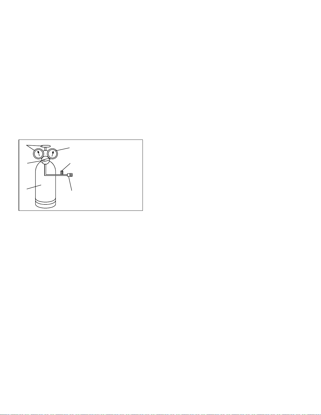
6.10.2 Checking High Pressure Switch
WARNING
Do not use a nitrogen cylinder without a
pressure regulator. Do not use oxygen in or
near a refrigeration system as an explosion
may occur.
NOTE
The high pressure switch is non-adjustable.
c. Unsolder discharge line and remove the line to the
receiver or water-cooled condenser.
d. Remove coil mounting hardware and remove the
coil.
e. Install replacement coil and solder connections.
f. Leak-check the coil connections per paragraphpara-
graph 6.5. Evacuate the unit per paragraph 6.6 then
chargethe unit with refrigerant per paragraph 6.7.
6.12 CONDENSER FAN AND MOTOR ASSEMBLY
a. Remove switch as outlined in paragraph6.10.1
b. C onnect ohmmeter or continuity light across switch
terminals. Ohm meter will indicate no resistance or
continuity light will be illuminated if the switch
closed after relieving compressor pressure.
c. Connect hose to a cylinder of dry nitrogen. (See
Figure 6-9.)
1
2
3
Figure 6-9 High Pressure Switch Testing
4
5
6
1. Cylinder Valve
and Gauge
2. Pressure Regulator
3. Nitrogen Cylinder
4. Pressure Gauge
(0 to 36 kg/cm@ =
0 to 400 psig)
5. Bleed-Off Valve
6. 1/4 inch Connection
d. Set nitrogen pressure regulator at 26.4 kg/cm@ (375
psig) with bleed-off valve closed.
e. Cl ose valve on cylinder and open bleed-off valve.
f. Open cylindervalve. Slowly closebleed-offvalveto
increasepressureon switch. The switch should open
at a static pressure up to 25 kg/cm@ (350 psig). If a
lightisused,lightwillgoout.Ifanohmmeterisused,
the meter will indicate open circuit.
g. Slowlyopenbleed-offvalvetodecreasethepressure.
The switch should close at 18 kg/cm@ (250 psig).
6.11 CONDENSER COIL
WARNING
Do not open condenser fan grille before
turning power OFF and disconnecting
power plug.
The condenser fan rotates counter-clockwise (viewed
from front of unit), pulls air through the the condenser
coil,anddischargeshorizontallythroughthefrontofthe
unit. To replace motor assembly:
a. Open condenser fan screen guard.
b. Loosen two square head set screws on fan. (Thread
sealer has been applied to set screws at installation.)
Disconnect wiring from motor junction box.
CAUTION
Take necessary steps (place plywood over
coil or use sling on motor) to prevent motor
from falling into condenser coil.
c. Remove motor mounting hardware and replace the
motor. It is recommendedthat new locknuts be used
when replacing motor. Connect wiring per wiring
diagram.
d. Install fan loosely on motor shaft (hub side in). DO
NOTUSEFORCE.If necessary,tapthehubonly,not
the hub nuts or bolts. Install venturi. Apply “Loctite
H”tofansetscrews.Adjust fan withinventurisothat
the outer edge of the fan is within 2.0 ± .07 mm
(0.08”¦ 0.03”)fromthe outside ofthe orificeopen-
ing. Spin fan by hand to check clearance.
e. Close and secure condenser fan screen guard.
f. Apply power to unit and check fan rotation. If fan
motor rotates backward, reverse wire numbers 5 and
8.
The condenser consists of a series of parallel copper
tubes expanded into copper fins. The condenser coil
mustbecleanedwithfreshwaterorsteamsotheairflow
is not restricted. To replacethe coil, do the following:
WARNING
Do not open the condenser fan grille before
turning power OFF and disconnecting
power plug.
a. Using a refrigerant reclaim system, remove the
refrigerant charge.
b. Remove the condenser coil guard.
6.13 FIL TER-DRIER
Onunitsequippedwitha water-cooledcondenser,ifthe
sight glass appears to be flashing or bubbles are
constantly moving through the sight glass when the
suction modulation valve is fully open, the unit may
havea low refrigerantchargeor thefilter-driercouldbe
partially plugged.
a. To Check Filter-Drier
1. Testforarestrictedorpluggedfilter-drierbyfeeling
the liquid line inlet and outlet connections of the
driercartridge.If theoutletside feels cooler than the
inlet side, then the filter-drier should be changed.
6-8T -309
Page 73
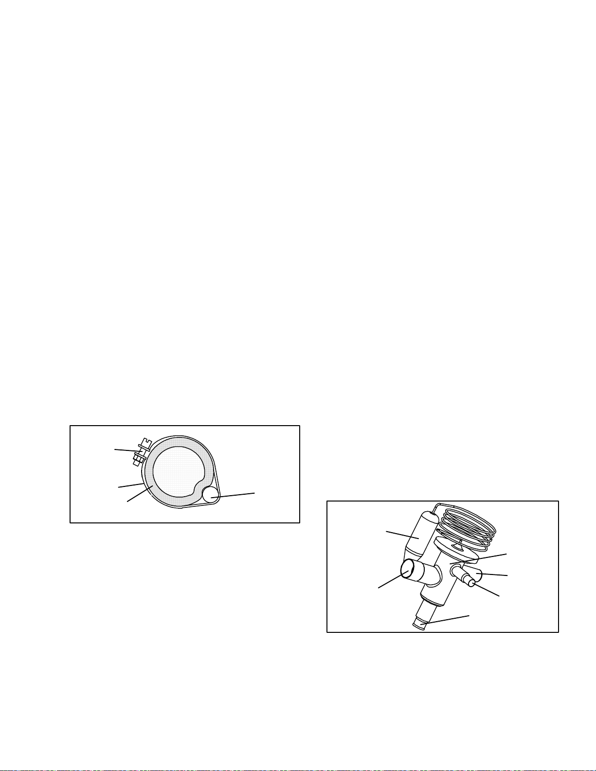
2. Check the moisture-liquid indicator if the indicator
showsahighlevelofmoisture,thefilter-driershould
be replaced.
b. To Replace Filter-Drier
1. Pump down the unit (refer to paragraph 6.4 and
replacefilter-drier.
2. Evacuate the low sidein accordancewith paragraph
6.6.
3. Afterunitisin operation,inspectformoistureinsystem and check charge.
6.14 EXPAN SION VALVES
Two expansion valves are used, the evaporator
expansion valve (item 9, Figure 2-2), and the
economizer expansion valve (item 26, Figure 2-4) .
The
expansionvalvesareautomaticdeviceswhichmaintain
constant superheat of the refrigerant gas leaving at the
pointof bulb attachmentregardlessof suctionpressure.
The valve functions are:
1. Automatic control of the refrigerant flow to match
the load.
2. Prevention of liquid refrigerant entering the com-
pressor.
a. Open the heater access panel (see Figure 2-1) to ex-
pose the evaporator expansion valve.
b. Attacha temperaturesensornearthe expansionvalve
bulb and insulate. Make surethe suctionline is clean
and that firm contact is made with the sensor.
c. Connect anaccurate gaugetothe serviceportdirectly
upstream of the suction m odulating valve.
d. Setthe temperaturesetpointto --18_C(0_F), andrun
unit until conditions stabilize.
e. The readingsmaycyclefromahigh toalowreading.
Take readings of temperature and pressure every
three to five minutes for a total of 5or 6 readings
f. From thetemperature/pressure chart (Table 6-7), de-
termine the saturation temperature corresponding to
the evaporator outlet test pressures at the suction
modulation valve.
g. Subtract the saturation temperatures determined in
stepf. fromthe temperaturesmeasuredinstep e.. The
difference is the superheat of the suction gas. Determinethe averagesuperheatIt should be 4.5 to 6.7°C
(8 to 12 °F)
6.14.2 Valve Replacement
a. Removing the Expansion Valve
Unless the valve is defective, it seldom requires
maintenance other than periodic inspection to ensure
thatthethermalbulbistightlysecuredtothesuctionline
and wrapped with insulating compound. (See
Figure 6-10.)
3
2
1
1. Suction Line
2. TXV Bulb Clamp
Figure 6-10 Thermostatic Expansion Valve Bulb
6.14.1 Checking Superheat.
3. Nut and Bolt
4. TXV Bulb
4
NOTE
Propersuperheatmeasurementfortheevaporator expansion valve should be completed at
-- 1 8 _C(0_F) container box temperature where
possible. If the economizer valve is suspect, it
should be replaced.
NOTES
1. TheTXV’sarehermeticvalvesanddonot
have adjustable superheat.
2. Allconnections on the evaporator TXV are
bi---metallic, copper on the inside and
stainless on the outside. When brazing,
bi---metallic connections heat up very
quickly.
6
1
2
5
3
4
1. Evaporator Expansion Valve
2. Non-adjustable Superheat Stem
3. Equalizer Connection
4. Inlet Connection
5. Outlet Connection
6. Expansion Valve Bulb
Figure 6-11 Evaporator Expansion Valve
6-9
T-309
Page 74

Copper Tube
(Apply heat for
10-15 seconds)
Braze Rod
(’Sil-Phos” = 5.5% Silver, 6% Phosphorus)
Bi-metallic Tube Connection
(Apply heat for 2-5 seconds)
Figure 6-12 Hermetic Thermostatic Expansion Valve Brazing Procedure
INLET
OUTLET
Figure 6-13 Economizer Expansion Valve
1. Pump down the unit per paragraph 6.4.
2. Removecushionclampslocatedon theinletandoutlet lines.
3. Unbrazetheequalizerconnection(ifapplicable),the
outlet connection and then the inlet connection.
4. Remove insulation (Presstite)fromexpansionvalve
bulb.
5. Unstrapthebulb,locatedbelowthecenterofthesuction line (4 o’clock position), andremovethe valve.
b. Installing the Expansion Valve
1. Clean the suction line with sandpaper before installing bulb to ensure properheat transfer. Apply thermal grease to the indentation in the suction line.
2. Strap the thermal bulb to the suction line, making
sure bulb is placed firmly into the suction line. See
Figure 6-10 for bulb placement.
3. Insulate the thermalbulb.
4. The economizer expansion valves should be
wrapped in a soaked cloth for brazing. See
Figure 6-12. Braze inlet connection to inlet line
5. Braze outlet connection to outlet line.
6. Reinstall the cushion clamps on inlet and outlet
lines.
Use of a wet cloth is not necessary due to rapid heat dissipation
of the bi--metallic connections
7. If applicable, braze the equalizer connection to the
equalizer line.
8. Check superheat (refer to step 6.14.1).
6.15 EVAPORATOR COIL AND HEATER
ASSEMBLY
The evaporator section, including the coil, should be
cleaned regularly. The preferred cleaning fluid is fresh
waterorsteam.AnotherrecommendedcleanerisOakite
202 or similar, following manufacturer’s instructions.
The two drain pan hoses are routed behind the
condenser fan motor and compressor. The drain pan
line(s) must be open to ensure adequate drainage.
6.15.1 Evaporator Coil Replacement
a. Pump unit down. (Refer to paragraph 6.4.)
b. With power OFF and power plug removed, remove
thescrews securingthepanel coveringtheevaporator
section (upper panel).
c. Disconnect the defrost heater wiring.
d. Disconnect the defrost temperature sensor (see Fig-
ure Figure 2-2 from the coil. .
e. Remove middle coil support.
f. Remove the mounting hardware from the coil.
g. Unsolder the twocoil connections, oneat thedistrib-
utor and the other at the coil header.
h. After defective coil is removed from unit, remove
defrost heaters and install on replacement coil.
i. Install coil assembly by reversing above steps.
j. Leak check connections perparagraph 6.5. Evacuate
the unit per paragraph6.6 and add refrigerant charge
per paragraph 6.7.
6.15.2 Evaporator Heater Replacement
a.Beforeservicingunit,makesuretheunitcircuitbreak-
ers(CB-1&CB-2)andthe start-stopswitch(ST)are
intheOFFposition,andthatthepowerplugandcable
are disconnected.
b. Remove the lower access panel (Figure 2-1) by
removing the T.I.R. locking device lockwire and
mounting screws.
6-10T-309
Page 75

c. Determine which heater(s) need replacing by check-
ing resistance on each heater. Refer to paragraph 2.3
for heater resistance values
d. Remove hold-down clamp securing heaters to coil.
e. Lift the bent end of the heater (with the opposite end
down and away from coil). Move heater to the side
enough to clear the heater end support and remove.
2 Be sure electrical power is removed from the unit.
Disconnect leads. Remove top screw and washer.
Lift off coil. (See Figure 6-14 or Figure 6-15)
3 Unbraze valve from unit and braze new valve in
place
4 Install coil. Evacuate low side and place unit back
in operation. Check charge.
6.16 ECONOMIZER, UNLOADER, LIQUID INJEC-
TION AND OIL RETURN SOLENOID VALVE
a. Replacing the Coil
NOTE
Thecoil maybereplaced withoutremovingthe
refrigerant.
1 Be sure electrical power is removed from the unit.
Disconnect leads. Remove top screw and washer.
Lift off coil. (See Figure 6-14 or Figure 6-15)
2 Verify coil type, voltage and frequency of old and
newcoil.This informationappearsonthecoilhousing.
Replacing Valve Internal Parts (Unloader
b.
Solenoid Only)
1 Pump down the unit. Refer to paragraph 6.4.
2 Be sure electrical power is removed from the unit.
Disconnect leads. Remove top screw and washer.
Lift off coil. (See Figure 6-14)
3 Remove the top screw (see Figure 6-14), washer ,
and coil assembly.
4 Loosen the enclosing tube locknut.
5 Remove enclosing tube and locknut assembly. The
gasket is inside the enclosing tube.
6 Removeseatdisc from inside of bodyand checkfor
obstructions and foreign material.
1
2
3
4
5
6
7
8
9
1. Top Screw
2. Washer
3. Coil
4. Locknut
5. Enclosing Tube
Figure 6-14. Unloader Solenoid Valve
1
2
3
6. Gasket
7. Stem and Plunger
8. Seat Disc
9. Body
7 Placetheseatdiscintothevalvebodywiththesmall-
er diameter end facing up.
8 Install stem and plunger.
9 Placethe enclosing tube locknut over the enclosing
tube. Install spacerover enclosingtubemakingsure
it is seated properly in the enclosing tube locknut.
Tightenenclosing tube locknut to a torque value of
2.78 mkg (20 ft-lb). Do not overtighten.
10 Install coil assembly, washer and top screw.
11 Evacuateanddehydratethesystem.(Refertosection
6.6.) Charge unit with refrigerant per section 6.7.
12 Start unit and check operation.
Replacing Valve
c.
1 To replace the unloader, liquid injection or econo-
mizervalve,pumpdowntheunit.Refertoparagraph
6.4. To replace the oil return valve, remove the re-
frigerant charge.
4
1. Slotted Screw
2. Washer
3. Coil
Figure 6-15. Oil Return Solenoid Valve (ORV),
Economizer Solenoid Valve (ESV), Liquid
Injection Solenoid Valve (LIV)
6.17 EVAPORATOR FAN AND MOTOR ASSEMBLY
4. Enclosing Tube and
Body
The evaporator fans circulate air throughout the
containerby pulling airin the top of the unit. The air is
forced through the evaporator coil where it is either
heatedor cooled and thendischarged out the bottom of
6-11
T-309
Page 76

the refrigeration unit into the container. The fan motor
bearings are factory lubricated and do not require
additional grease.
6.17.1 Replacing The Evaporator Fan Assembly
WARNING
Always turn OFF the unit circuit breakers
(CB-1 & CB-2) and disconnect main power
supply before working on moving parts.
a. Remove upper access panel (see Figure 2-2) by
removing mounting bolts and T.I.R. locking device.
Reach insideof unit and removetheTy-Rapsecuring
thewire harness loop. Then unplug the connectorby
twisting to unlock and pulling to separate.NOTE: It
maybeeasiertounplug theconnectorwiththemotor
assembly partially pulled out (after step b).
b. Removethe four mounting bolts that secure the mo-
tor--fan assembly to the unit.
c. Slide the fan assembly out from the unit and place it
on a sturdy work surface.
d. Remove the motor and fan from the assembly.
e. Replace the motor.
f. Lubricate the fan motor shaft with a graphite--oil
solution (Never--Seez) and apply thread sealer (Loc-
tite H, brown in color) to the two fan set screws.
Installfanonthemotorshaft,sothatthecouplingsur-
face will be even with the end of the m otor shaft.
g. Install the fan assembly in reverse order of removal.
Apply power momentarily to check for proper fan
rotation(refertoparagraph2.3).Ifthefanspinsback-
wards, than motor wiring or motor is defective.
Replace access panel making sure that panel does not
leak. Lock--wire the T.I.R. locking device(s).
4
5
6
1. Bracket
2. Flat washer, 3/8
3. Bolt, 3/8-16 x 1.00
4. Locknut, 5/16-18
5. Flat washer, 5/16
3
2
1
8
9
7
6. Cap Screw, Hxhd
5/16-18 x 1.25
7. Fan
8. Shim
9. Evaporator Motor
Figure 6-16. Evaporator Fan Assembly
6.18 EVAPORATOR FAN MOTOR CAPACITORS
The evaporator fan motors are of the permanent-split
capacitor type. The motor is equipped with one
capacitor used in the high speed circuit and another
capacitor used for the low speed circuit.
6.18.1 When To Check For A Defective Capacitor
a. Fan motor willnot changespeed.Forexample:in the
conventionalperishablemode,themotorsshouldrun
in high speed. In the economy perishable mode they
shouldswitchspeedsand in the frozenmode,themotors should run in low speed.
NOTE
The evaporator fan motors will always start in
high speed.
b. Motor running in wrong direction (after checking
for correct wiring application).
c. Motor will not start, and IP-EM’s are not open.
6.18.2 Removing The Capacitor
WARNING
Make sure power to the unit is OFF and
power plug disconnected before removing
capacitor(s).
The capacitors are located on the motor and above the
evaporator fan deck they may be removed by two
methods:
1 If container is empty, open upper rear panel of the
unit. Thecapacitormaybeservicedafterdisconnecting power plug.
2 If container is full, turn the unit power OFF anddis-
connect power plug. Remove the evaporator fan
motor access panel. (See see Figure 2-1). For
removal of theevaporator fanassembly,refer to section 6.17.
WARNING
WithpowerOFFdischargethecapacitorbeforedisconnectingthe circuitwiring.
6.18.3 Checking The Capacitor
If the capacitor is suspected of malfunction, you may
choosetosimplyreplaceit. Direct replacementrequires
a capacitor of the same value. Two methods for
checking capacitor function are:
1. Volt-ohmmeter set on RX 10,000 ohms.
Connect ohmmeter leads across the capacitorterminals
and observe the meter needle. If the capacitor is good,
the needle will make a rapid swing toward zero
resistance and thengradually swing back toward a very
high resistance reading.
If the capacitor has failed open, the ohmmeter needle
will not move when the meter probes touch the
terminals. If the capacitor is shorted, the needle will
swing to zero resistance position and stay there.
2. Capacitor analyzer:
The function of the analyzer is to read the microfarad
valueof acapacitorand to detect insulation breakdown
6-12T-309
Page 77

under load conditions. The important advantages of a
(py
)
(g)
(qg
,
analyzer are its ability to locate capacitors that have
failedto hold their microfaradratings, or those that are
breaking down internally during operation. It is also
useful in identifying capacitors when their microfarad
rating marks have become unreadable.
6.19 VAL VE OVERRIDE CONTROLS
CAUTION
DONOTdisassemblepiston fromNEWsuction modulating valve powerhead assembly.
Doing so may result in damage to piston.
Controller function code Cd41 is a configurable code
that allows timed operation of the automaticvalves for
troubleshooting.Threetestsequencesareprovided.The
first, capacity mode (CAP), allows alignment of the
unloader and economizer solenoid valves in the
standard, unloaded and economized operating
configurations. The second, SMV % Setting (SM)
allows opening of the suction modulating valve to
various percentages and the third, Oil Valve Setting
(OIL)andLiquidValveSetting(LIV)allowsopeningor
closing of the oil return solenoid valve and the liquid
injection solenoid valve. A fourth selection is also
provided to enter a time period of up to three minutes,
during which the override(s) are active. If the timer is
active, valve override selections will take place
immediately.If the timer is not active, changes willnot
take place for a few seconds after the timer is started.
When the timer times out, override function is
automatically terminated and the valves return to
normal machinery control. To operate the override, do
the following:
a. PresstheCODESELECTkeythenpressanARROW
key until Cd41 is displayed in the left window. The
right window will display a controller communications code.
b. Press the ENTER key. The left display will show a
test name alternating with the test setting or time remaining.UseanARROWkeyto scrollto thedesired
test. Press the ENTER key and SELCt will appearin
the left display.
c. Use an ARROW key to scroll to the desiredsetting,
and then press the ENTER key. Selectionsavailable
for each of the tests are provided in the following
table.
d. If the timer is not operating, follow theabove proce-
dure to display the timer. Use an ARROW key to
scrolltothedesiredtimeintervalandpressENTERto
start the timer.
e. The above described sequence maybe repeated dur-
ing the timer cycle to change to another override.
Right Display Available Selections
CAP
(Capacity Mode)
Economizer = Closed)
Economizer = closed)
SM
(SMV% Setting)
OIL
(Oil Valve Setting)
(Liquid Valve Setting, if
6.20 SUCTION MODULATION VALVE
LIV
applicable)
tIM
(Timer)
000(0 minutes/0 Seconds)
In 30 second increments to
300(3 minutes/ 0 seconds)
AUtO
(Normal Control)
UnLd
(Unloader = Open
Std
(Unloader = closed
ECOn
(Unloader = closed
Economizer = open)
AUtO
(Normal Control)
0
3
4
6
12
25
50
100
AUto
(Normal Control)
CLOSE
OPEn
AUto
(Normal Control)
CLOSE
OPEn
On start up of the unit, the valve will reset to a known
open position. This is accomplished by assuming the
valve was fully open, driving it fully closed, resetting
the percentage open to zero, then opening to a known
10% staging position.
FROM COIL
FROM UNLOADER
Figure 6-17 Suction Modulation Valve (SMV)
2-1/8 inch Nut
TO COMPRESSOR
6-13
T-309
Page 78

6.20.1 Precheck Procedure
a. Check unit for abnormal operation.
b. Check charge. If refrigerant is low repair as required
and again check operation.
c. If sufficient capacity cannot be maintained or unit is
tripping excessively on high pressure switch (HPS)
in high ambients, check coils and clean if required.
d. If capacity or control cannot be maintained turn unit
OFF, then back ON. This will reset the valve in the
event the controller lost communication with the
valve, and may correct the problem.
NOTE
Carefully listen to the valve. During reset, the
valve will make a ratcheting noise that may be
heard or felt as it is attempting to close. If this
canbeheard or felt, itindicates that thecontrolleranddrivemoduleareattemptingtoclosethe
valve, and may serve as aquick indication t hat
the drive is in working order.
e. Operation ofthe valvemaybechecked usingthecon-
troller valve override program, function code Cd41.
Refer to paragraph 6.19 for valve override test instructions.
6.20.2 Checking The Stepper valve
a. Checking with ohmmeter
Disconnect the four pin connector to the stepper SMV.
With a reliable digital ohmmeter, check the winding
resistance.In normalambient,the valveshould have72
to 84 ohms measured on the red/green (a-b terminals)
and on the white/black (c-d terminals) leads. If an
infinite or zero reading occurs, check connections and
replacethe m otor.
b. CheckingwithSMA-12 portablestepper drive tester
The SMA-12 portable s tepper drive tester (Carrier
Transicold P/N 07-00375-00) is a battery operated
stepperdrivewhichwillopenandclosetheSMV, which
allows a more thorough check of the operating
mechanism.
To check operation:
1. Stoptheunit,disconnectthefourpinconnectorfrom
thesteppermoduletothevalve(see
Figure 6-17)and
attachtheSMA-12stepperdrivetotheconnectorgoingtothevalve.
2. Set the SMA-12pulse per second(PPS)to onePPS
and either open or close valve. Each LED should
lightsequentiallyuntilallfourarelit.AnyLEDfail-
ing to light indicatesanopen on that legwhich indicatesa poor connectionoranopen coil. Repair or replace as required to achieve proper operation.
CAUTION
The scroll compressor achieves low suction
pressure very quickly. Do not operate the
compressor in a deepvacuum,internaldamage will result.
3. Restart unit, set the steprateto200PPS onSMA-12
forthevalve,andclosesteppervalvewhilewatching
the suction gauge. Within one minute t he suction
pressurewillgointo avacuum.This is anindication
that the valve is moving.
4. If no change in suction pressure is detected, check
for resistance (refer to step 6.20.2), and check connectionsforpropercontinuityandretest.Ifthevalve
is functioning and all connections and motor resistance are good, check the controller and expansion
module.
CAUTION
DONOTdisassemblepiston fromNEWsuction modulating valve powerhead assembly.
Doing so may result in damage to piston.
5. If the valve is determinedas faulty after completing
theabovesteps,performalowsidepump down. Removevalvepowerheadassembly,andreplacewith a
NEWvalvepowerheadassembly,torquenutto35ftlb, evacuate low side, and open all service valves.
6.21 CONTROLLER AND EXPANSION MODULE
6.21.1 Handling Modules
CAUTION
Do not remove wireharnesses from module
unless you are grounded to the unit frame
with a static safe wrist strap.
CAUTION
Unplug all module connectors before performingarc welding on any part of the container.
The guidelines and cautions provided herein should be
followed when handling the modules. These
precautions and procedures should be implemented
when replacinga module, when doing any arc welding
on the unit, or when service to the refrigeration unit
requires handling and removal of a module.
6-14T-309
Page 79

12
5
1. Controller Software
Programming Port
2. Mounting Screw
3. Controller
4. Expansion Module
5. Test Points
Figure 6-18 Controller Section of the Control Box
2
3
4
a. Obtain a grounding wrist strap (Carrier Transicold
part number 07--00--304-- 00)and a static dissipation
mat (Carrier Transicold part number 07--00304--00.
The wrist strap, when properly grounded, will dissipate any potential buildup on the body. The dissipation mat will provide a static-free work surface on
which to place and/or service the modules.
b. Disconnect and secure power to the unit.
c. Place strapon wrist andattach the ground endto any
exposed unpainted metal area on the refrigeration
unit frame (bolts, screws, etc.).
d. Carefullyremovethemodule.Donottouchanyofthe
electrical connections if possible. Place the module
on the static mat.
e. The strapshouldbe worn duringanyserviceworkon
a module, even when it is placed on the mat.
6.21.2 Controller Trouble-Shooting
Agroupoftestpoints(TP,seeFigure 6-18)areprovided
on the controllerfor trouble-shooting electricalcircuits
(seeschematicdiagram, section 7). Adescriptionofthe
test points follows:
NOTE
Use a digital voltmeter to measure ac voltage
between TP’s and ground (TP9), except for
TP8.
TP1
Thistestpoint enablesthe user to checkif thecontroller
unloader solenoid valve relay (TU) is open or closed.
TP2
This test point enables the user to check if the high
pressure switch (HPS) is open or closed.
TP3
This test point enables the user to check if the water
pressure switch (WP) contact is open or closed.
TP 4
This test point enables the user to check if the internal
protectorforthecondenserfanmotor(IP-CM)is openor
closed.
TP 5
This test point enables the user to check if the internal
protectors for the evaporator fan motors (IP-EM1 or
IP-EM2) are open or closed.
TP 6
This test point is not used in this application.
TP 7
Thistestpoint enablesthe user to checkif thecontroller
economizersolenoidvalve relay(TS) is open orclosed
TP 8
This test point enables the user to check power to the
suction modulator valve.
TP 9
This test point is the chassis (unit frame) ground
connection.
TP 10
This test point enables the user to check if the heat
terminationthermostat(HTT)contactis open or closed.
6.21.3 Controller Programming Procedure
Toloadnewsoftwareintothemodule,theprogramming
card is inserted into the programming/software port.
CAUTION
The unit mustbe OFF whenever aprogramming card is inserted or removed from the
controller programming port.
NOTE
Themetal door on the programmingcard must
be facing to the left when inserting.
a. Procedure for loading Operational Software
1. Turn unit OFF, via start-stop switch (ST).
2. Insert the programming card for Operational Software into the programming/software port. (See
Figure 6-18)
3. Turn unit ON, via start-stop switch (ST).
4. The Display module will alternate back and forth
between the messages “rEV XXXX” and “Press
EntR”. (If a defectivecard isbeingused the Display
willblink the message“bAdCArd”. Turnstart-stop
switch OFF and remove the card.)
6-15
T-309
Page 80
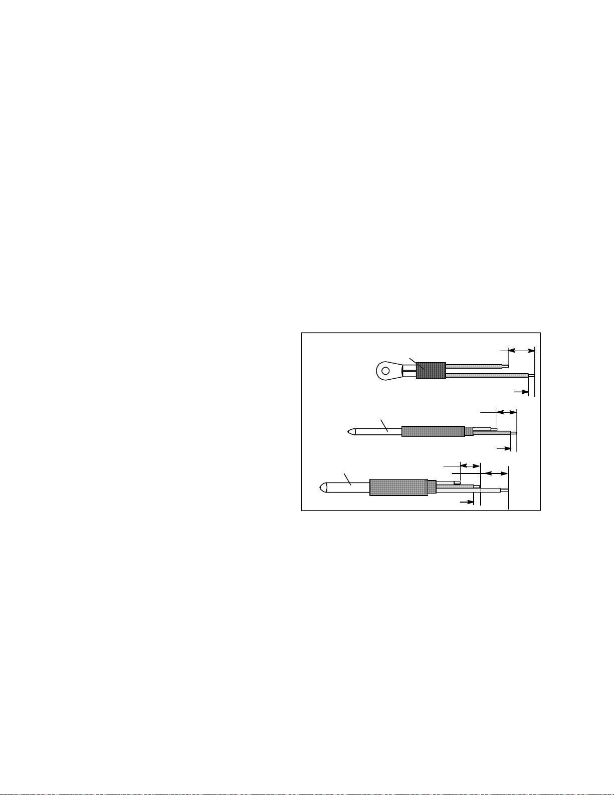
5. Press the ENTER key on the keypad.
3 Disconnectthebackconnectorsandremovemodule.
6. TheDisplaywillshowthemessage“ProSoFt.”This
message will last for up to one minute.
7. The Display module will read “Pro donE” when the
software loading has loaded. (If a problem occurs
while loading the software: the Display will blink
the message “Pro FAIL” or “bad 12V”. Turn startstop switch OFF and remove the card.)
8. Turn unit OFF, via start-stop switch (ST).
9. Remove the programming card from the programming/softwareportandreturnthe unit to normaloperation by placing the start-stop switch in the ON
position.
b. Procedurefor loading ConfigurationSoftware
1. Turn unit OFF using start-stop switch (ST).
2. Insert the programming card, for Configuration
Software,into the programming/softwareport. (See
Figure 6-18.)
3. Turn unit ON using start-stop switch (ST).
4. The Display module will show “nt40” on the left
LCD display and “531###” on the right LCD display.“###”willindicatethe dash numberforagiven
unit model number,usethe UP orDOWN ARROW
key to scroll through the list to obtain the proper
model dash number. For example, to program a
model number 69NT40-531-05, press the UP or
DOWN ARROW key until the right display shows
“nt40” on the right display and “53105” on the left.
(If a defective card is being used, the Display will
blink the message “bAd CArd”. Turn start-stop
switch OFF and remove the card.)
5. Press the ENTER key on the keypad.
4 When removing the replacement module from its
packaging, notehowitispackaged.Whenreturning
theold module for service,placeit in the packaging
in thesame manner as the replacement. Thepackaging has been designed to protect the module from
both physical and electrostatic discharge damage
during storage and transit.
b.Installation:
Install the module by reversing the removal steps.
Torque values for mounting screws (item 2, see
Figure 6-18) are 0.23 mkg (20 inch-pounds). Torque
value for the connectors is 0.12 mkg (10 inch-pounds).
6.22 TEMPERATURE SENSOR SERVICE
Procedures for service of the Return Recorder, Return
Temperature, Supply Recorder, Supply Temperature,
Ambient, Defrost Temperature, Compressor Discharge
and Compressor Suction temperature sensors are
provided in the following sub paragraphs.
6.22.1 Sensor Checkout Procedure
Mounting Stud Type
40 mm (1 1/2 inch)
6.3 mm (1/4 inch)
40 mm (1-1/2 inches)
6.3 mm (1/4 inch)
Bulb Type
Dual Sensor
Sensor
Sensor
40 mm (1-1/2 inches)
6. When the software loading has successfully completed, the Display will show the message “EEPrM
donE.” (If a problem occurs while loading the software,theDisplaywillblinkthemessage“ProFAIL”
or “bad 12V.” Turn start-stop switch OFF and
remove the card.)
7. Turn unit OFF using start-stop switch (ST).
8. Remove the programming card from the programming/softwareportandreturnthe unit to normaloperation by placing the start-stop switch in the ON
position.
6.21.4 Removing and Installing a Module
a. Removal:
1. Disconnect all front wire harness connectors and
move wiring out of way.
2 The lower controller mounting is slotted, loosen the
topmountingscrew(seeFigure 6-18) andliftupand
out.
6.3 mm (1/4 inch)
Figure 6-19 Sensor Types
Tocheck a sensor reading, do the following:
a. Removethesensorandplacein a0_C(32_F)ice-wa-
ter bath. The ice-water bath is preparedby filling an
insulated container (of sufficient size to completely
immersebulb)withicecubesor chippedice,thenfilling voids between ice with water and agitating until
mixture reaches 0_C(32_F) measured on a labora-
tory thermometer.
b. Start unit and check sensor reading on the control
panel.Thereadingshould be0_C(32_F).Ifthe read-
ing is correct, reinstall sensor; if it is not, continue
with the following.
c. Turn unit OF F and disconnect power supply.
d. Refertoparagraph6.21andremovecontrollertogain
access to the sensor plugs.
6-16T-309
Page 81

Table 6-2 Sensor Temperature/Resistance Chart
C
F
(+/--.002%)
Temperature
____C ____F
Resistance
(Ohms)
AMBS,
CPSS,
DTS, RTS,
RRS, STS,
SRS
CPDS
-- 3 0 -- 2 2 177,000 1,770,000
-- 2 5 -- 1 3 130,400 1,340,000
-- 2 0 -- 4 97,070 970,700
-- 1 5 5 72,900 729,000
-- 1 0 14 55,330 553,000
-- 5 23 43,200 423,300
0 32 32,650 326,500
5 41 25,390 253,900
10 50 19,900 199,000
15 59 15,700 157,100
20 68 12,490 124,900
25 77 10,000 100,000
30 86 8,060 80,600
35 95 6,530 65,300
40 104 5,330 53,300
45 113 4,370 43,700
50 122 3,600 36,000
55 131 2,900 29,000
60 140 2,490 24,900
65 149 2,080 20,800
65 158 1,750 17,500
e. Using the plug connector marked “EC”, that is con-
nectedto the back of the controller, locate the sensor
wires (RRS, RTS, SRS, STS, AMBS, DTS, CPDS
ORCPSSasrequired).Followthosewirestotheconnector and using the pins of the plug, measure the
resistance. V alues are provided in Table 6-2.
Dueto the variationsand inaccuracies in ohmmeters,
thermometers or other test equipment, a reading
within 2% of the chart value would indicate a good
sensor.If asensor is defective, theresistancereading
will usually be much higher or lower than the resistance values given.
6.22.2 Sensor Replacement
a. Turn unit power OFF, disconnect power supply and
remove sensor assembly from unit.
b. Cut wire(s) 5 cm (2 inches) from shoulder of defec-
tive sensor and discard the defective probe only.
c. Cut one wire of existing cable 40 mm (1-1/2 inch)
shorter than the other wire.
d. Cut one replacement sensor wire (opposite color)
back 40 mm (1-1/2 inch). (See Figure 6-19.)
e. Strip backinsulationon all wiring 6.3mm (1/4 inch).
f. Slide a large piece of heat shrink tubing over the
cable, and place the two small pieces of heat shrink
tubing, one over each wire, before adding crimp fit-
tings as shown in Figure 6-20.
Sensor (Typical)
Heat Shrink
Cable
Large Heat Shrink
Tubing (1)
Figure 6-20 Typical Sensor and Cable Splice
Tubing (3)
g. Slip crimp fittings over dressed wires (keeping wire
colors together). Make sure wires are pushed into
crimpfittingsasfaraspossibleandcrimpwithcrimp-
ing tool.
h. Solder spliced wires with a 60% tin and 40% lead
Rosincore solder.
i. Slide heat shrink tubing over splice so that ends of
tubing cover both ends of crimp as shown in
Figure 6-20.
j. Heattubingtoshrinkoversplice.Makesureallseams
are sealedtightly against thewiringto prevent mois-
ture.
k. Slide large heat shrink tubing over both splices and
shrink.
CAUTION
Do not allow moisture to enter wire splice
area as this may affect thesensorresistance.
l. Position sensor in unit as shown in m.Figure 6-21
Slip crimp fittings over dressed wires (keeping wire
colors together). Make sure wires are pushed into
crimp fittings as far as possible and crimp with
crimping tool. and re--check sensor resistance.
n. Reinstall sensor, refer to paragraph 6.22.3.
NOTE
The P5 Pre-Trip test must be run to inactivate
probe alarms (refer to paragraph 4.7).
6-17
T-309
Page 82

T.I.R. Bolts
Supply
Air
Stream
Insulation
STS probe
Back Panel
Supply Sensor
Mounting
Clamp
Sensor
Wires
Gasketed
Cover
Gasketed
Support
Plate
6.22.3 Sensor Re--Installation
a. Sensors STS and SRS
2.5” Drip Loop
Figure 6-21 Supply Sensor Positioning
Gasket
Mounting
Plate
Toproperlyposition asupplysensor,thesensormustbe
fully inserted into the probe holder. Do not allow heat
shrink covering to contact the probeholder. Forproper
placement ofthe sensor,besure topositiontheenlarged
positioning section of the sensor against the the side of
the mounting clamp. This positioning will give the
sensor the optimum amount of exposure to the supply
air stream, and will allow the Controller to operate
correctly. See Figure 6-21.
b Sensors RRS and RTS
Reinstallthereturnsensorasshownin Figure 6-22. For
proper placement of the return sensor, be sure to
position the enlarged positioning section of the sensor
against the the side of the mounting clamp.
SRS probe
c Sensor DTS
The DTS sensor must have insulating material placed
completely over the sensor to insure the coil metal
temperature is sensed.
6.23 MAINTENANCE OF PAINTED SURFACES
The refrigeration unit is protected by a special paint
system against the corrosive atmosphere in which it
normallyoperates.However,should thepaint systembe
damaged, thebase metalcancorrode. Inorder toprotect
the refrigeration unit from the highly corrosive sea
atmosphere, or if the protective paint system is
scratched or damaged, clean area to bare metal using a
wirebrush,emerypaperorequivalentcleaningmethod.
Immediately following cleaning, apply 2--part epoxy
paint to the area. and allow to dry. After the first coat
dries, apply a second coat.
Mounting
Clamp
Figure 6-22 Return Sensor Positioning
Return Sensor
1.50 in.
(38.1cm)
6.24 COMPOSITE CONTROL BOX REPAIRS
6.24.1 Introduction
This procedure provides instructions for repair of the
Carrier Transicold composite control box. Damage to
the control box may be in the form of a chip or hole, a
crack, a damaged thread insert or damage to the door
hingeinserts.Generally,theobjectoftherepairmustbe
to ensuresufficient strength is restoredto the damaged
area and t he repair must keep the box water tight.
Informationon repairkitsandrepairprocedures foreach
typeofdamageis providedin the followingparagraphs.
Ambient temperature must be above 7°C(45°F) for
proper curing of epoxy repairs.
6-18T-309
Page 83

6.24.2 Cracks
Cracks in thecontrol box arerepairedusing a fiberglass
patch over the damaged area. Materials required are
includedintheFiberglassPatchKitsuppliedwithCrack
Repair Kit, Carrier Transicold part number
76-00724-00SV (see Table6-3).
a. The surface must be cleanand dry.Roughen the sur-
face with sandpaper to ensure a good bond.
b. Cut the fiberglass cloth to allow a 25mm (1--inch)
overlap around the area to be repaired.
c. Stretch and position the cloth over the area to be re-
paired and secureit with masking tape.
d. Make up sufficient epoxy glue to cover the cloth by
mixingequalpartsofresin andhardener.Saturatethe
cloth with the epoxy glue, spreading evenly.
e. Remove the tape and overlap the edge of the cloth
approximately 6 to 12 mm (1/4” to 1/2”) with glue.
f. Epoxy will dry in 45--60 minutes. When completely
cured (12 hours), use sandpaper to smooth edges of
the patch.
6.24.3 Chips And Holes
Chips and holes in the control box are repaired using a
piece of aluminum or stainless steel to cover the
damagedarea.Thematerialcanbecuttosuitandriveted
in place. An adhesive sealant must be usedto make the
repairwatertight.Theadhesivesealant(Sikaflex221)is
included in Crack Repair Kit Carrier Transicold part
number76-00724-00SV(seeTable6-3).Do notusean
acetone based silicone sealant (Which can be
identified by a vinegar--like odor).
The damaged insert must be removed from the control
box. Table 6-5 identifiesthe drill size and drill depthto
beusedforeachinsert.Astopringshould beusedonthe
drill bit to limit the depth.
a. Center the drill bit on the insert and drill to the pre-
scribed depth.
b. Remove the chips from the drilled hole.
c. Mix t he two component epoxy and fill the hole 1/2
way to the top with epoxy.
d. Press the insert in until it is flush with the surface.
e. Wipe away any excess epoxy. The part is ready for
service after the bond material has hardened and is
tack free (approximately 20 minutes)
6.24.5 Door Hinge Inserts
Ifthedoorhinges havebeenpulledfromthecontrolbox
drillandreinstallthe hingeasshownin Figure 6-23and
described in the following steps.
a. To make up the patch, cut a piece of aluminum or
stainlesssteelso thatit will overlap thedamaged area
by at least 40 mm (1 1/2”) on all sides.
b. C hoose rivet locations and drillthe rivet holes in the
correspondinglocationsonthecontrolbox and patch
piece.
c. Apply theadhesive sealant around the damagedarea
to form a s eal between the control box and the patch
piece.
d. Rivet the patch piece in place.
e. File smooth any rough edges (including rivets) that
may come into contact with wires.
6.24.4 Inserts
The threaded brass inserts that are molded into the
control box will need to be replaced if the threads
become stripped, or if the insert becomes loose. The
inserts and epoxy are contained in repair kit, Carrier
Transicold part number 76-50084-00 (see Table 6-4).
There are 6 different inserts used in the control box.
Refer to Figure 6-24 for the locations of the various
inserts.
NOTE
Anepoxyapplicationgunisalsoneeded,Carri-
er Transicold part number 07 -- 00391 -- 00.
Figure 6-23 Door Hinge Repair
Materials needed:
1. Cut two square pieces of 3 mm thick (1/8 inch) aluminum or stainless steel approximately 40 mm (1
5/8”) square. These squares will serve as backing
plates.
2. Twonuts, bolts (10 -- 24 x 1”) and washers foreach
insert that needs repair.
a. Drill a 1/4” holein the center of each square backing
plate.
b. Pass the bolts through the bolts holes in the door
hinge, then through the control box at the location
where the hinge insert pulled out.
c. From inside the controlbox, slide the backing plates
over the bolts and secure in place with the washers
and nuts.
6-19
T-309
Page 84

Table 6-3 Crack, Chip & Hole Repair Kit
ITEM DESCRIPTION PART NUMBER Qty
1 Crack Repair Kit -- Includes 76--00724--00SV 1
2 Fiberglass Patch Kit (Loctite FK--98 or 80265)... 76--00724--00Z 10
3 Sikaflex 221 Adhesive Sealant (Sikaflex 232--361)... 02--00067--02Z 10
4 Instruction Sheet... 98--02339--00 10
Table 6-4 Insert Repair Kit
ITEM DESCRIPTION PART NUMBER Qty
1 Insert Repair Kit -- Includes 76--50084--00 1
2 Insert - 17.53 x 9.91 mm (..690 x .390 in) 1/4--20 Threads... 34--06231--01 10
3 Insert - 15.88 x 6.35 mm (.625 x .250 in) 10-24 Threads... 34--06231--03 10
4 Insert - 25.15 x 7.54 mm (.990 x .297 in) 10-24 Threads... 34--06231--04 10
5 Insert - 10.16 x 9.53 mm (.400 x .375 in) 10-24 Threads... 34--06231--05 10
6 Insert - 12.7 x 9.91 mm (.5 x .390 in) 1/4--20 Threads... 34--06231--06 10
7 Insert - 9.53 x 6.76 mm (.375 x .266 in) 10-24 Threads... 34--06231--07 10
8 Durabond Epoxy E20--HP (Loctite 29314)... 02--0082--00 1
9 Static Mixing Tube (Loctite 983440)... 07--00390--00 1
10 Instruction Sheet... 98--02338--00 1
Note: Insert repair procedures require use of an Application Gun, Carrier part number 07--00391--00
Table 6-5 Drill Information
Item
Insert part number Drill size and depth
1 34- 06231- 01 10.3 mm x 17.8 mm deep (.404 in. x .700 in. deep)
2 34- 06231- 03 6.8 mm x 16.3 mm deep (.266 in. x .640 in. deep)
3 34- 06231- 04 7.9 mm x 25.4 mm deep (.3125 in. x 1.0 in. deep)
4 34- 06231- 05 6.9 mm (.270 in.) Drill completely through.
5 34- 06231- 06 10.3 mm (.404 in.) Drill completely through.
6 34- 06231- 07 6.8 mm (.266 in.) Drill completely through.
6-20T-309
Page 85
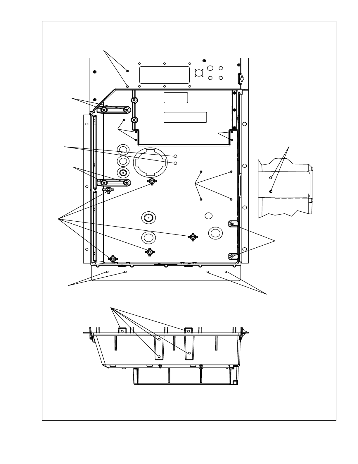
04
03
01
06
07
04
03
03
05
03
03
07
05
Figure 6-24. Insert Location
6-21
INSERT PART NUMBERS 34--06231--## WHERE THE ## IS AS INDICATED
T-309
Page 86

6.25 COMMUNICA TIONS INTERFACE MODULE
INSTALLATION
CB1
Communications
interface Module
c.. Remove the circuit breaker panel, with circuit
breaker, from the control box.
d.. Locate, wires CB21/CIA3, CB22/CIA5 and
CB23/CIA7 that have been tied back in the wire
harness.Removetheprotectiveheatshrinkfromthe
ends of the wires.
e.. Attach the three wires as addressed to the LOAD
side of the circuit breaker.
f.. Refit the circuit breaker panel.
g. Fit the new RMU into the unit.
h. Remove plugs CIA, CIB and CID from thewiring
harness and attach to the module.
.i. Replace the low voltage shield.
Table 6-6 Recommended Bolt Torque Values
Figure 6-25. Communications Interface
Installation
Units with communication interface module provision
havetherequiredwiringinstalled.Theprovisionwiring
kit (part number 76--00685--00), includes three
pre--addressed wires installed between the circuit
breakerandcommunicationinterfacemodulelocations.
These wires are to be connected to the module and
circuit breaker to allow the module to communicate
over the power system. To install the module, do the
following:
WARNING
The Unit Power Plug Must Be Disconnected
To Remove Power From Circuit Breaker
Cb1
a.. CB1 is connected to the power system, see wiring
schematic. Ensure that the unit power is off AND
that the unit power plug is disconnected.
b.. Open control box, see Figure 6-25 and remove low
voltage shield. Open high voltage shield.
BOLT DIA.
#4
#6
#8
#10
1/4
5/16
3/8
7/16
1/2
9/16
5/8
3/4
NONFREE SPINNING (LOCKNUTS ETC.)
1/4
5/16
3/8
7/16
1/2
9/16
5/8
3/4
THREADS TORQUE MKG
FREE SPINNING
40
32
32
24
20
18
16
14
13
12
11
10
20
18
16
14
13
12
11
10
5.2 in-lbs
9.6 in-lbs
20 in-lbs
23 in-lbs
75 in-lbs
11 ft-lbs
20 ft-lbs
31 ft-lbs
43 ft-lbs
57 ft-lbs
92 ft-lbs
124 ft-lbs
82.5 in-lbs
145.2 in-lbs
22.0 ft-lbs
34.1 ft-lbs
47.3 ft-lbs
62.7 ft-lbs
101.2 ft-lbs
136.4 ft-lbs
0.05
0.11
0.23
0.26
0.86
1.52
2.76
4.28
5.94
7.88
12.72
17.14
0.95
1.67
3.04
4.71
6.54
8.67
13.99
18.86
6-22T-309
Page 87
Table 6-7 R-134a Temperature - Pressure Chart
Temperature
____F ____C “/hg cm/hg kg/cm@@@@ bar
Vacuum
-- 4 0 -- 4 0 14.6 49.4 37.08 0.49
.35 .37 12.3 41.6 31.25 0.42
-- 3 0 -- 3 4 9.7 32.8 24.64 0.33
-- 2 5 -- 3 2 6.7 22.7 17.00 0.23
-- 2 0 -- 2 9 3.5 11.9 8.89 0.12
-- 1 8 -- 2 8 2.1 7.1 5.33 0.07
-- 1 6 -- 2 7 0.6 2.0 1.52 0.02
Temperature Pressure
____F ____C psig kPa kg/cm@@@@ bar
-- 1 4 -- 2 6 0.4 1.1 0.03 0.03
-- 1 2 -- 2 4 1.2 8.3 0.08 0.08
-- 1 0 -- 2 3 2.0 13.8 0.14 0.14
-- 8 -- 2 2 2.9 20.0 0.20 0.20
-- 6 -- 2 1 3.7 25.5 0.26 0.26
-- 4 -- 2 0 4.6 31.7 0.32 0.32
-- 2 -- 1 9 5.6 36.6 0.39 0.39
0 -- 1 8 6.5 44.8 0.46 0.45
2 -- 1 7 7.6 52.4 0.53 0.52
4 -- 1 6 8.6 59.3 0.60 0.59
6 -- 1 4 9.7 66.9 0.68 0.67
8 -- 1 3 10.8 74.5 0.76 0.74
10 -- 1 2 12.0 82.7 0.84 0.83
12 -- 11 13.2 91.0 0.93 0.91
14 -- 1 0 14.5 100.0 1.02 1.00
16 -- 9 15.8 108.9 1.11 1.09
18 -- 8 17.1 117.9 1.20 1.18
20 -- 7 18.5 127.6 1.30 1.28
22 -- 6 19.9 137.2 1.40 1.37
24 -- 4 21.4 147.6 1.50 1.48
26 -- 3 22.9 157.9 1.61 1.58
Temperature Pressure
____F ____C psig kPa kg/cm@@@@ bar
28 -- 2 24.5 168.9 1.72 1.69
30 -- 1 26.1 180.0 1.84 1.80
32 0 27.8 191.7 1.95 1.92
34 1 29.6 204.1 2.08 2.04
36 2 31.3 215.8 2.20 2.16
38 3 33.2 228.9 2.33 2.29
40 4 35.1 242.0 2.47 2.42
45 7 40.1 276.5 2.82 2.76
50 10 45.5 313.7 3.20 3.14
55 13 51.2 353.0 3.60 3.53
60 16 57.4 395.8 4.04 3.96
65 18 64.1 441.0 4.51 4.42
70 21 71.1 490.2 5.00 4.90
75 24 78.7 542.6 5.53 5.43
80 27 86.7 597.8 6.10 5.98
85 29 95.3 657.1 6.70 6.57
90 32 104.3 719.1 7.33 7.19
95 35 114.0 786.0 8.01 7.86
100 38 124.2 856.4 8.73 8.56
105 41 135.0 930.8 9.49 9.31
110 43 146.4 1009 10.29 10.09
115 46 158.4 1092 11.14 10.92
120 49 171.2 1180 12.04 11.80
125 52 184.6 1273 12.98 12.73
130 54 198.7 1370 13.97 13.70
135 57 213.6 1473 15.02 14.73
140 60 229.2 1580 16.11 15.80
145 63 245.6 1693 17.27 16.93
150 66 262.9 1813 18.48 18.13
155 68 281.1 1938 19.76 19.37
6-23
T-309
Page 88

SECTION 7
ELECTRICAL WIRING SCHEMATIC
7.1 INTRODUCTION
This section contains the Electrical Schematics and Wiring Diagrams. The diagrams are presented as follows:
Figure 7-1 Provides the legend for use with all figures.
Figure 7-2 Provides the basic schematic diagram.
Figure 7-3 Provides t he basic wiring diagram.
Sequence of operation descriptions for the various modes of operation are provided in paragraph 4.9
SYMBOL DESCRIPTION (Schematic Location)
LEGEND
AMBS AMBIENT SENSOR (C--21)
C CONTROLLERS (H-21, H-23)
CB1 CIRCUITBREAKER -- 460 VOLT (J--1)
CB2 CIRCUITBREAKER -- AUTOTRANSFORMER (C--1)
CF CONDENSER FAN CONTACTOR (M--12, N--5)
CI COMMUNICATIONS INTERFACEMODULE (A--3)
CL COOL LIGHT (J--7)
CM CONDENSER FANMOTOR (H--12, T-5)
CP COMPRESSOR MOTOR (T--1)
CPDS COMPRESSOR DISCHARGE SENSOR (A--22)
CPSS COMPRESSOR SUCTION SENSOR (D--21)
CR CHART RECORDER [TEMPERATURE RECORDER]
CS CURRENT SENSOR (M--1)
DHBL DEFROST HEATER -- BOTTOM LEFT (T--4)
DHBR DEFROST HEATER -- BOTTOM RIGHT (R--4)
DHTL DEFROST HEATER -- TOP LEFT (T--4)
DHTR DEFROST HEATER -- TOP RIGHT (R--4)
DL DEFROST LIGHT (J--6)
DPT DISCHARGE PRESSURE TRANSDUCER (J--22)
DTS DEFROST TEMPERATURESENSOR (B--22)
DVM DUAL VOLTAGE MODULE (D--1)
DVR DUAL VOLTAGE RECEPTACLE (F--1)
E1 EVAPORATOR FANCONTACTOR [HIGH]
EM EVAPORATOR FANMOTOR (E--13,G--13,T--8,T--11)
ES EVAPORATOR FAN CONTACTOR [LOW]
ESV ECONOMIZER SOLENOID VALVE (K--17)
F FUSE (C--6,D--20,E--20,H--4)
FLA FULL LOAD AMPS
HPS HIGH PRESSURE SWITCH (G--11)
HR HEATERCONTACTOR (L--15,N--3)
HS HUMIDITY SENSOR (F--21)
HTT HEAT TERMINATION THERMOSTAT (G--15)
IC INTERROGATOR CONNECTOR [FRONT/REAR]
IP INTERNAL PROTECTOR (E--13,G--13,H--12)
IRL IN RANGE LIGHT (J8)
LIV LIQUID INJECTION SOLENOID VALVE (K-18)
MDS MANUAL DEFROST SWITCH (E--19)
(K-16)
(L--13,L--14,P--7,P--10)
( M-- 1 4, P -- 7, P -- 11 )
(P--22,P--21)
SYMBOL DESCRIPTION (Schematic Location)
ORV OIL RETURN SOLENOID VALVE (N--24,H-9)
PA COMPRESSOR PHASE CONTACTOR (L--11,M--10,P1)
PB COMPRESSOR PHASE CONTACTOR (L--10,M--11,P2)
PR PROBE RECEPTACLE [USDA]
RM REMOTE MONITORING RECEPTACLE
RRS RETURN RECORDER SENSOR (K--21)
RTS RETURN TEMPERATURE SENSOR (B--21)
SMV SUCTION MODULATING VALVE (K--24)
SPT SUCTION PRESSURE TRANSDUCER (H--21)
SRS SUPPLY RECORDER SENSOR (K--22)
ST START -- STOP SWITCH (K--4)
STS SUPPLY TEMPERATURE SENSOR (A--21)
TCC TransFRESH COMMUNICATIONS
TD CONTROLLER RELAY -- COOLING (H11)
TE CONTROLLER RELAY -- HIGH
TFC TransFRESHCONTROLLER (G--5)
TH CONTROLLER RELAY -- HEATING(K--15)
TN CONTROLLER RELAY -- CONDENSER FAN (K--12)
TP TEST POINT (F--17,G--12,H--11,J--12,
TR TRANSFORMER (M--3)
TRANS AUTO TRANSFORMER 230/460 (D--1)
TRC TransFRESH REAR CONNECTOR (E--5)
TS CONTROLLER RELAY -- ECONOMIZER SOLENOID
TT CONTROLLER RELAY -- COOLING (C--11)
TU CONTROLLER RELAY -- UNLOADER SOLENOID
TV CONTROLLER RELAY -- LOW SPEED EVAPORATOR
T1 CONTROLLER RELAY -- RM COOL (G --7)
T2 CONTROLLER RELAY -- RM DEFROST (G--6)
T4 CONTROLLER RELAY -- RM INRANGE (G--8)
T6 CONTROLLER RELAY -- COMPRESSOR PHASE
USV UNLOADER SOLENOID VALVE(K--16)
WP WATER PRESSURE SWITCH (E--12)
D--21,L--22,M--22)
(J-6,J--7,K--6,K--7,K--8)
CONNECTOR (D-4)
SPEED EVAPORATOR FANS
(K--13)
J--13,J--15,M--19)
VALVE (E--17)
VALVE (E--16)
FANS (K--14)
SEQUENCING (K--10,K--11)
Figure 7-1 LEGEND
7-1
T-309
Page 89

Figure 7-2 SCHEMATIC DIAGRAM
7-2T -309
Page 90
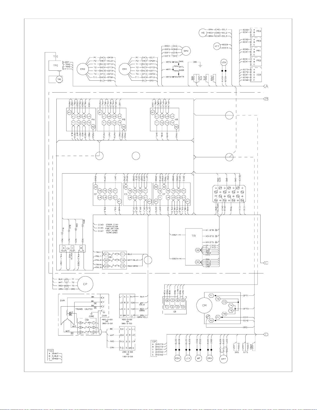
Figure 7-3 WIRING DIAGRAM (Sheet 1 of 2)
7-3
T-309
Page 91

Figure 7-3 WIRING DIAGRAM (Sheet 2 of 2)
7-4T -309
Page 92

INDEX
A
Air Cooled Condenser Section, 2-4
Alarm, 3-6, 3-10, 3-12, 3-17, 3-27
B
Battery, 1-1
C
Capacitors, 6-12
Checking Superheat, 6-9
Communications, 1-1
Communications InterfaceModule, 3-11, 6-21
Compressor, 1-1, 6-5
Compressor Phase Sequence, 4-5
Compressor Section, 2-3
Condenser Coil, 1-1, 6-8
Condenser Fan, 6-8
E
Evacuation, 6-3
Evaporator, 6-10
Evaporator Fan, 6-12
Evaporator Section, 2-2
Expansion Module, 3-1, 6-14
Expansion Valves, 6-10
F
Failure Action, 3-4
Filter--Drier, 6-8
Fresh Air Makeup, 2-1, 4-1
Frozen Mode, 4-6
Frozen Mode -- Conventional, 3-6
Frozen Mode -- Economy, 3-6
Function Code, 3-14, 3-25
Configuration Identification, 1-1
Configuration Software, 3-3, 3-8
Configuration Variables, 3-13
Control Box, 1-1, 2-5, 6-18
Controller, 3-3, 6-14
Controller Software, 3-3
D
DataCORDER, 3-7, 3-10, 4-2
DataCORDER Software, 3-7
DataReader, 3-11
DataView, 3-11
Defrost Interval, 3-4
Defrost Mode, 4-7
Dehumidification, 1-1
Display Module, 3-2
G
General Description, 2-1
Generator Protection, 3-4
H
Heat Lockout, 3-4, 3-6
Heater, 6-10
Heating Mode, 4-6
High Pressure Switch, 6-7
I
Inspection, 4-1, 4-2
Interrogator, 1-1
Introduction, 1-1
Index-1 T-309
Page 93

INDEX
K
Key Pad, 3-2
L
Leak Checking, 6-3
Logging Interval, 3-10
M
Manifold Gauge Set, 6-1
MicroporcessorSystem, 3-1
Modes Of Operation, 3-4
O
Oil, 6-7
Operational Software, 3-4, 3-7
Refrigeration Circuit, 2-10
RefrigerationSystem Data, 2-6
Refrigeration Unit -- Front Section, 2-1
Remote Monitoring, 1-1
S
Safety and Protective Devices, 2-8
Sampling Type, 3-10
Scroll Back , 3-10
Sensor Configuration, 3-8
Sequence Of Operation, 4-5
Service Valves, 6-1
Solenoid Valves, 6-10
Starting, 4-2
Stopping, 4-2
Suction Modulating Valve, 6-13
Option Descriptions, 1-1
P
Painted Surfaces, 6-17
Perishable Mode -- Bulb, 3-5
Perishable Mode -- Conventional, 3-4
Perishable Mode -- Dehumidification, 3-5
Perishable Mode -- Economy, 3-5
Power, 4-1
Pre--Trip, 3-7, 3-10, 3-21, 3-26, 4-2
Pressure Readout, 1-1
Probe Check, 4-3
Pumping Down, 6-2
R
Refrigerant Charge, 6-4
T
TemperatureControl, 3-4, 3-6
Temperature Sensor, 6-17
Thermistor F ormat, 3-10
Torque Values, 6-21
U
Upper Air, 1-2
V
Valve Override Controls, 6-12
W
Wiring Schematic, 7-1
T-309
Index-2
 Loading...