


50HC Series
Carrier 50HC Series, 50HC08, 50HC09, 50HC11, 50HC12 Service And Maintenance Instructions
...
50HC
Single Package Rooft op Electric Cooling Unit
with Puron (R---410A) Refrigerant
3 to 12.5 Nominal Tons (Sizes 04---14)
Service and Maintenance Instructions
TABLE OF CONTENTS
SAFETY CONSIDERATIONS 1....................
UNIT ARRANGEMENT AND ACCESS 2...........
SUPPLY FAN (BLOWER) SECTION 4..............
STAGED AIR VOLUME CONTROL --2 SPEED FAN
WITH VARIABLE FREQUENCY DRIVE (VFD) 7....
ADDITIONAL VARIABLE FREQUENCY DRIVE
(VFD) INSTALLATION AND TROUBLESHOOTING. 8
MOTOR 8......................................
COOLING 12...................................
THERMOSTATIC EXPANSION VALVE (TXV) 14....
PURONR (R--410A) REFRIGERANT 15.............
COOLING CHARGING CHARTS 17................
COMPRESSOR 21...............................
CONVENIENCE OUTLETS 24....................
SMOKE DETECTORS 25.........................
SENSOR AND CONTROLLER TESTS 29...........
PROTECTIVE DEVICES 32.......................
PREMIERLINK CONTROL 33...................
RTU--OPEN CONTROL SYSTEM 33................
SENSORY/ACCESSORY INSTALLATION 34........
ADDITIONAL RTU--OPEN INSTALLATION AND
TROUBLESHOOTING 34.........................
ECONOMIZER UNITS 36........................
PRE-- START --UP/START- -UP 44....................
START--UP, GENERAL 45........................
START--UP, PREMIERLINK CONTROLS 46.......
START--UP, RTU--OPEN CONTROLS 46............
FASTENER TORQUE VALUES 47.................
APPENDIX I. MODEL NUMBER SIGNIFICANCE 48.
APPENDIX II. PHYSICAL DATA 49................
APPENDIX III. FAN PERFORMANCE 52...........
APPENDIX IV WIRING DIAGRAMS 71............
APPENDIX V. MOTORMASTER SENSOR
LOCATIONS 121................................
UNIT STAR T-UP CHECKLIST 124.................
SAFETY CONSIDERATIONS
Installation and servicing of air-conditioning equipment
can be hazardous due to system pressure and electrical
components. Only trained and qualified service personnel
should install, repair, or service air-conditioning
equipment. Untrained personnel can perform the basic
maintenance functions of replacing filters. Trained service
personnel should perform all ot her operations.
When working on air-conditioning equipment, observe
precautions in the literature, tags and labels attached to
the unit, and other safety precautions that may apply.
Follow all safety codes. Wear safety glasses and work
gloves. Use quenching cloth for unbrazing operations.
Have fire extinguishers available for all brazing and
unbrazing operations.
Read these instructions thoroughly and follow all
warnings or cautions attached to t he unit. Consult local
building codes and National Electrical Code (NEC) for
special requirements.
Recognize safety information. This is the safety ALERT
symbol
instructions or manuals, be aware of the potential for
physical injury hazards.
Understand the signal words DANGER, WARNING,and
CAUTION. These words are used with the safety--ALERT
symbol. DANGER indicates a hazardous situation which,
if not avoided, will result in death or severe personal
injury. WARNING indicates a hazardous situation which,
if not avoided, could result in death or personal injury.
CAUTION indicates a hazardous situation which, if not
avoided, could result in minor to moderate injury or
product and propert y damage. NOTICE is used to address
practices not related to physical injury. NOTE is used to
highlight suggestions which will result in enhanced
installation, reliability, or operation.
. When you see this symbol on the unit and in
!
WARNING
!
WARNING
ELECTRICAL OPERATION HAZARD
Failure to follow this warning c ould re sult in personal
injury or death.
Before performing service or maintenance operati ons
on unit, LOCK--OUT/TAGOUT the main power
switch to unit. Electrical shock and rotating equipment
could cause severe injury.
!
WARNING
ELECTRICAL OPERATION HAZARD
Failure to follow this warning c ould re sult in personal
injury or death.
50HC
Units with convenience outlet circuits can use
multiple disconnects. Check convenience outlet for
power status before opening unit for service. Locate
the disconnect switch and lock it in the open position
it. LOCK--OUT/TAGOUT this switch to notify others.
!
WARNING
UNIT OPERATION AND SAFETY HAZARD
Failure to follow this warning could cause personal
injury, death and/or equipment damage.
Puron (R--410A) refrigerant systems operate at higher
pressures than standard R--22 systems. Do not use
R--22 service equipment or components on Puron
refrigerant equipment.
!
WARNING
FIRE, EXPLOSION HAZARD
Failure to follow this
warning could result in
death, serious personal
injury and/or property
damage.
Never use non--certified refrigerants in this product.
Non--certified refrigerants could contain contaminates
that could lea d to unsafe operating conditions. Use
ONLY refrigerants that conform to AHRI Standard
700.
!
CAUTION
UNIT DAMAGE HAZARD
Failure to follow this caution may result in reduced
unit performance or unit shutdown.
High velocity water from a pressure washer, garden
hose, or compressed air should never be used to
clean a coil. The force of the water or air jet will
bend the fin edges and increa se airside pressure drop.
NOTICE
OPERATIONAL TEST ALERT
Failure to follow this ALERT can result in an
unnecessary evacuation of the facility.
Pressing the controller’s test/reset switch for longer
than seven seconds will put the duct detector into the
alarm state and activate all automatic alarm responses.
FIRE, EXPLOSION HAZARD
Failure to follow this
warning could result in
death, serious personal
injury and/or property
damage.
Never use air or gases containing oxygen for leak testing
or for operating refrigerant compressors. Pressurized
mixtures of air or gases containing oxygen can lea d to an
explosion.
IMPORTANT: Lockout/Tagout is a term used when
electrical power switches are physically locked
preventing power to the unit. A placard is placed on
the power switch alerting service personnel that the
power is disconnected.
UNIT ARRANGEMENT AND
ACCESS
General
Fig. 1 and Fig. 2 show general unit arrangement and
access locations.
2
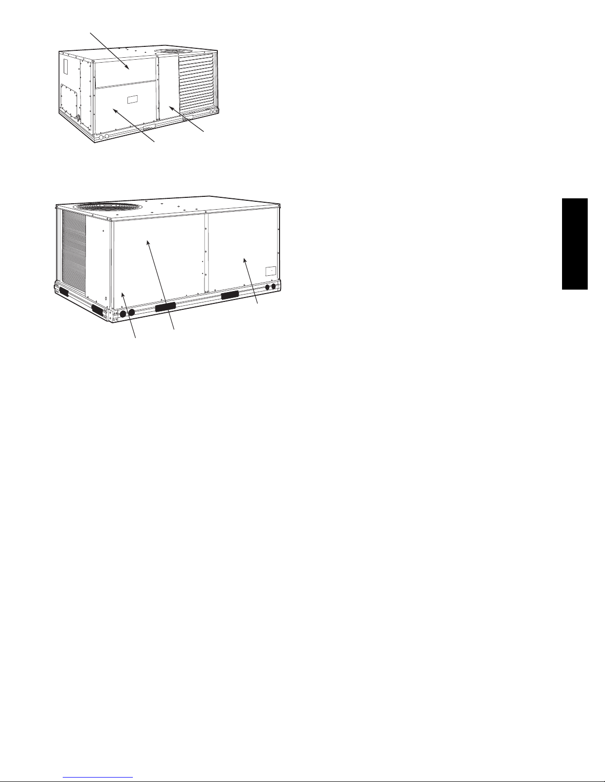
FILTER ACCESS PANEL
OUTDOOR-AIR OPENING AND
INDOOR COIL ACCESS PANEL
Fig. 1 -- Typical Access Panel Locations
COMPRESSOR
ACCESS PANEL (04-07 only)
C08449
Routine Maintenance
These items should be part of a routine maintenance
program, to be checked every month or two, until a
specific schedule for each can be identified for this
installation:
Quarterly Inspection (and 30 days after initial start)
S Return air filter replacement
S Outdoor hood inlet filters cleaned
S Belt tension and condition checked
S Pulley alignment checked
S Fan shaft bearing locking collar tightness checked
S Condenser coil cleanliness checke d
S Condensate drain checked
Seasonal Maintenance
50HC
These items should be checked at the beginning of each
season (or more often if local conditions and usage
patterns dictate):
COMPRESSOR
CONTROL BOX
(08-09 only)
Fig. 2 -- Blower Access Panel Location
BLOWER
ACCESS
PANEL
C160062
Air Conditioning
S Condenser fan motor mounting bolts tightness
S Compressor mounting bolts
S Condenser fan blade positioning
S Control box cleanliness and wiring condition
S Wire terminal tightness
S Refrigerant charge level using chart
S Evaporator coil cleaning
S Evaporator blower and condenser motor amperage
Economizer or Outside Air Damper
S Inlet filters condition
S Check damper travel (economizer)
S Check gear and dampers for debris and dirt
Air Filters and Screens
Each unit is equipped with return air filters. If the unit has
an economizer, it will also have an outside air screen. If a
manual outside air damper is added, an inlet air screen
will also be present.
Each of these filters and screens will need to be
periodically replaced or cleaned.
3
SUPPLY FAN (BLOWER) SECTION
!
WARNING
ELECTRICAL SHO CK HAZARD
Failure to follow this warning could cause personal
injury or death.
Before performing service or maintenance operations
on unit, LOCK--OUT/TAGOUT the main power
switch to unit. Electrical shock and rotating
equipment could cause severe injury.
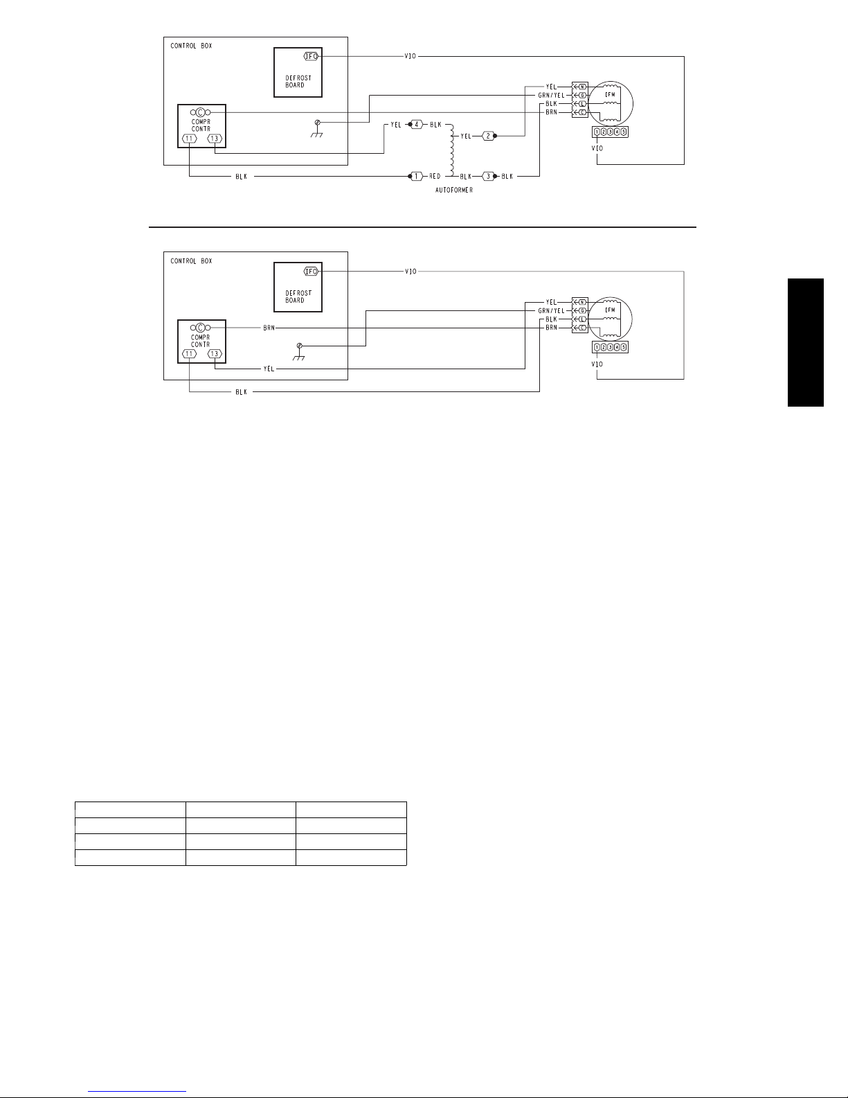
connected to motor terminals L and N (see Fig. 4 and
Fig. 5); ground is connected at terminal G. The motor
power voltage is ALWAYS present; it is not switched off
by a motor contactor.
L2
YEL
Com
BRN
L1
BLU
Gnd
GRN/YEL
C
LGN
Motor
Power
Connections
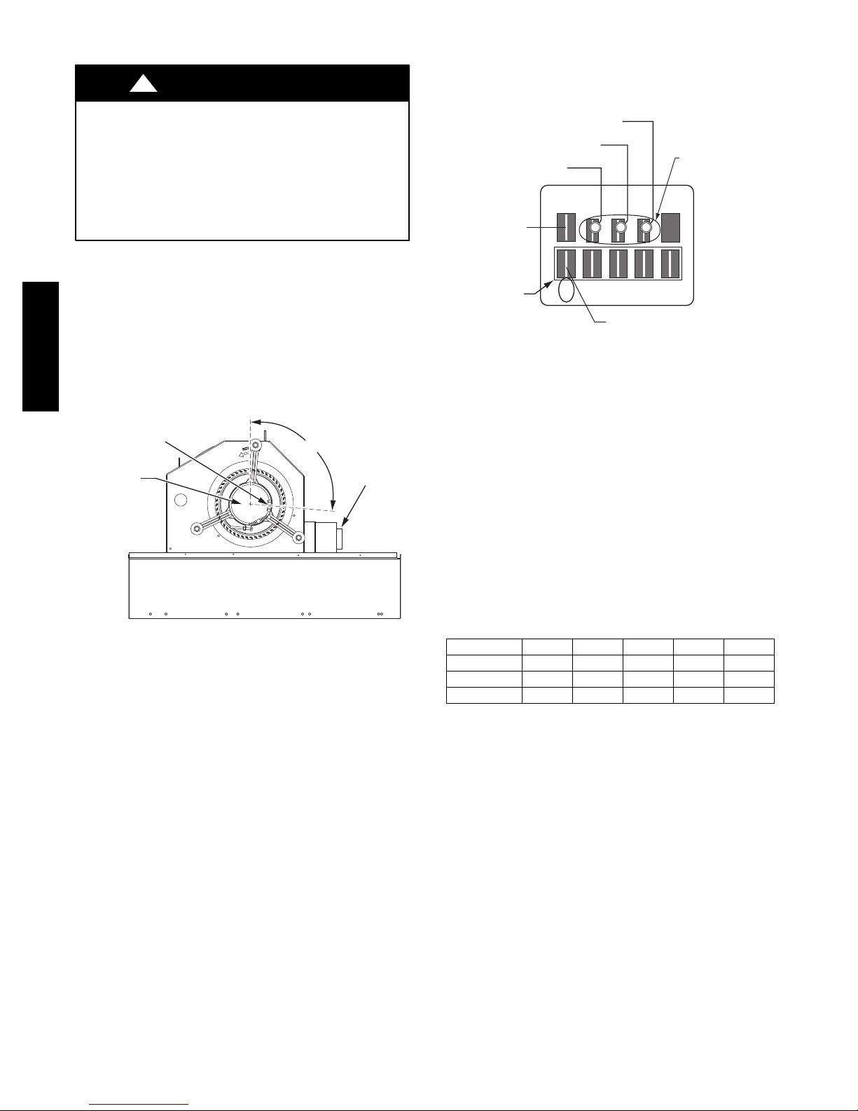
Supply Fan (Direct--Drive)
For unit sizes 04, 05 and 06, a direct--drive
forward-- curved centrifugal blower wheel is an available
option. The motor has taps to provide the servicer with the
selection of one of five motor torque/speed ranges to best
50HC
match wheel performance with attached duct system. See
Fig. 3 and Fig. 4 .
Motor Plug Position
(95° from vertical)
ECM Motor
Fig. 3 -- Direct-- Drive Supply Fan Assembly
ECM Motor — The direct--drive motor is an X13
Electronically Commutated Motor (ECM). An ECM
motor contains electronic circuitry used to convert
single--phase line AC voltage into 3--phase DC voltage to
power the motor circuit. The motor circuit is a DC
brushless design with a permanent ma gnet rot or. On the
X13 ECM Motor design, the electronic circuitry is
integral to the motor assembly and cannot be serviced or
replaced separately.
208/230V units use a 230V motor. 460V units use a 230V
motor with a stepdown transformer (mounted on the end
of the fan housing, see Fig. 3). 575V units use a 460V
motor with an autotransformer. Motor power voltage is
95°
ECM Power
Transformer
(460, 575v)
C09260
Speed
Taps
12345
VIO
Default Connection
C09261
Fig. 4 -- ECM Motor Connectors
Evaluating motor speed — The X13 ECM Motor uses a
constant torque motor design. The motor speed is adjusted
by the motor control circuitry to maintain the programmed
shaft torque. Consequently there is no specific speed value
assigned to each control tap setting. At the Position 5 tap,
the motor speed is approximately 1050 RPM (17.5 r/s) but
varies depending on fan wheel loading.
Selecting speed tap — The five communication terminals
are each programmed to provide a different motor torque
output. See Table 1. Factory default tap selection is
Position 1 for lowest torque/speed operation.
Table 1 – Motor Tap Programing
(percent of full--load torque)
Unit Size Ta p 1 Ta p 2 Ta p 3 Ta p 4 Ta p 5
04 32 38 45 50 100
05 46 58 61 69 100
06 73 82 85 90 100
Factory Default: Tap 1 (VIO)
Selecting another speed:
1. Disconnect main power to the unit. Apply
lockout/tagout procedures.
2. Remove the default motor signal lead (VIO) from
terminal 1 at the motor communications terminal.
3. Reconnect the motor signal lead to the desired speed
(terminals 1 through 5).
4. Connect main power to the unit.
4
460, 575-v Units
208/230-v Units
Fig. 5 -- Direct-- Drive Supply Fan Assembly
50HC
C09260
Motor “rocking” on start--up — When the motor first
starts, the rotor (and attached wheel) will “rock” back and
forth as the motor tests for rotational direction. Once the
correct rotational direction is determined by the motor
circuitry, the motor will ramp up to the specified speed.
The “rocking” is a normal operating characteristic of
ECM mot ors.
Troubleshooting the ECM motor — Troubleshooting the
X13 ECM requires a voltmeter.
1. Disconnect main power to the unit.
2. Remove the motor power plug (including the control
BRN lead) and VIO control signal lead at the motor
terminals.
3. Restore main unit power.
4. Check for proper line voltage at motor power leads
BLK (at L terminal) and YEL (at N terminal). See
Table 2.
Table 2 – Motor Test Volts
Unit Voltage Motor Voltage Min ---Max Volts
208/230 230 190---250
460 230 210--- 250
575 460 420--- 500
5. Using a jumper wire from unit control terminals R to
G, engage motor operation. Check for 24v output at
the defrost board terminal IFO.
6. Check for proper control signal voltages of 22V to
28V at motor signal leads VIO and BRN.
7. Disconnect unit main power. Apply lockout/tagout
procedures.
8. Reconnec t motor power and control signal leads at
the motor terminals.
9. Restore unit main power.
10. The motor should start and run. If the motor does not
start, remove the motor assembly. Replace the motor
with one having the same part number. Do not
substitute with an alternate design motor as the
torque/ speed programming will not be the same as
that on an original factory motor.
Replacing the X--13 ECM Motor — Before removing
the ECM belly--band mounting ring from old motor:
1. Measure the distance from base of the motor shaft to
the edge of the mounting ring.
2. Remove the motor mounti ng band and transfer it to
the replacement motor.
3. Position the mounting band at the same distance that
was measured in Step 1.
4. Hand--tighten mounting bolt only. Do not tighten
securely at this time.
5. Insert the m otor shaft into t he fan wheel hub.
6. Securely tighten the three motor mount arms to the
support cushions and torque the arm mounting screws
to 60 in--lbs (6.8 Nm).
7. Center the fan wheel in the fan housing. Tighten the
fan wheel hub setscrew and torque to 120 in--lbs (13.6
Nm).
8. Ensure the motor terminals are located at a position
below the 3 o’clock position (see Fig. 3). Tighten the
motor belly--band bolt and torque to 80 in--lbs (9.0
Nm).
Supply Fan (Belt--Drive)
The belt--drive supply fan system consists of a
forward--curved centrifugal blower wheel on a solid shaft
with two concentric type bearings, one on each side of the
5
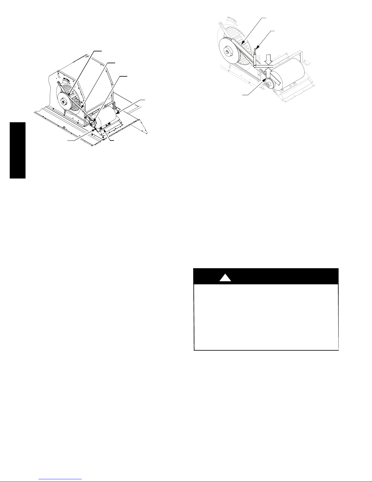
blower housing. A fixed--pitch driven pulley is attached to
the fan shaft and an adjustable--pitch driver pulley is on
the motor. The pulleys are connected using a V--belt. (See
Fig. 6.).
BLOWER PULLEY
V --- B E LT
MOTOR
PULLEY
MOTOR
MOUNTING
BOLTS (4)
MOTOR MOUNTING
PLATE
50HC
Fig. 6 -- Typical Belt Drive Motor Mounting
Belt
Check the belt condition and tension quarterly. Inspect the
belt for signs of cracki ng, fraying or glazing along the
inside surfaces. Check belt tension by using a spring--force
tool, such as Browning’s “Belt Tension Checker” (p/n:
1302546 or equivalent tool); tension should be 6--lbs at a
5
/8--in (1.6 cm). deflection when measured at the
centerline of the belt span. This point is at the center of
the belt when measuring the distance between the motor
shaft and the blower shaft.
NOTE: Without the spring--tension tool, place a straight
edge across the belt surface at the pulleys, then push down
on the belt at mid--span using one finger until a
(1.3 cm) deflection is reached. See Fig. 7.
Adjust belt tension by loosening the motor mounting plate
front and rear bolts and sliding the plate toward the fan (to
reduce tension) or away from fan (to increase tension).
Ensure the blower shaft and the motor shaft are parallel to
each other (pulleys aligned). When finished, tighten all
bolts and torque to 65--70 in--lb (7.4 to 7.9 Nm).
C11504
1
/2-- i n .
STRAIGHTEDGE
BROWNING BELT
TENSION CHECKER
1/2”
(1.3 cm)
BELT
DEFLECTION
C12025
Fig. 7 -- Checking Blower Motor Belt Tension
Replacing the Belt:
NOTE: Use a belt with same section type or similar size.
Do not substitute a FHP--type belt. When installing the
new belt, do not use a tool (screwdriver or pry--bar) to
force the belt over the pulley flanges, this will stress the
belt and cause a reduction in belt life. Damage to the
pulley can also occur.
Use the following steps to replace the V--belt. See Fig. 6.
1. Loosen the front and rear motor mounting plate bolts.
2. Push the motor and its mounting plate towards the
blower housing as c lose as possible to reduce the
center distance between fan shaft and motor shaft.
3. Remove the belt by gently lifting the old belt over
one of the pulleys.
4. Install the new belt by gently sliding the belt over
both pulleys and then sliding the motor and plate
away from the fan housing until proper tension is
achieved.
CAUTION
!
EQUIPMENT DAMAGE HAZARD
Failure to follow this CAUTION can result in
premature wear and damage to equipment.
Do not use a screwdriver or a pry bar to pl ace the new
V--belt in the pulley groove. This can cause stress on
the V--belt and the pulley resulting in premature wear
on the V--belt and damage to the pulley.
5. Check the alignment of the pulleys, adjust if necessary.
6. Tighten all bolts and torque to 65--70 in--lb (7.4 to 7.9
Nm).
7. Check the tension after a few hours of runtime and
re--adjust as required.
Adjustable--Pitch Pulley on Motor
The motor pulley is an adjustable--pitch type that allows a
servicer to implement changes in the fan wheel speed to
match as--installed ductwork systems. The pulley consists
of a fixed flange side that faces the motor (secured to the
motor shaft) and a movable flange side that can be rotated
6
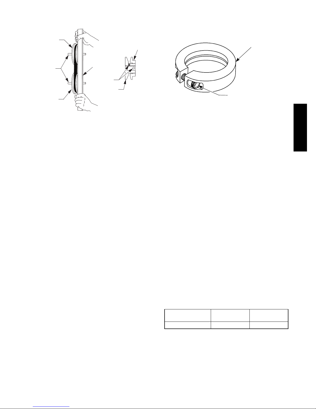
around the fixed flange side that increases or reduces the
pitch diameter of this driver pulley. (See Fig. 8.)
FAN PULLEY
MOTOR AND
FANSHAFTS
MUST BE
PARALLEL
MOTOR PULLEY
STRAIGHT EDGE
MUST BE PARALLEL
WITH BELT
SETSCREWS
FIXED FLANGE
SINGLE - GROOVE
MOVABLE
FLANGE
C07075
Fig. 8 -- Supply--Fan Pulley Adjustment
condition of the motor pulley for signs of wear. Glazing of
the belt contact surfaces and erosion on these surfaces are
signs of improper belt tension and/or belt slippage. Pulley
replacement can be necessary.
LOCKING COLLAR
T --- 2 5 T O R X S O C K E T
HEAD CAP SCREW
C11505
Fig. 9 -- Tightening Locking Collar
As the pitch diameter is changed by adjusting the position
of the movable flange , the centerline on this pulley shifts
laterally (along the motor shaft). This creates a
requirement for a re alignment of the pulleys after any
adjustment of the movable flange. Reset the belt tension
after each realignment.
Inspect the condition of the motor pulley for signs of
wear. Glazing of the belt contact surfaces and erosion on
these surfaces are signs of improper belt tension and/or
belt slippage. Replace pulley if wear is excessive.
Changing the Fan Speed:
1. Shut off unit power supply. Use proper lockout/tagout
procedures.
2. Loosen belt by l oosening fan motor mounting nuts.
(See Fig. 6.)
3. Loosen movable pulley fla nge setscrew. (See Fig. 8.)
4. Screw movable flange toward fixed flange to increase
speed and away from fixed flange to decrease speed.
Increasing fan speed increases load on motor. Do not
exceed the maximum specified speed.
5. Set movable flange at nearest keyway of pulley hub.
Tighten setscrew and torque to 65--70 in--lb (7.4 to 7.9
Nm).
Aligning Blower and Motor Pulleys:
1. Loosen blower pulley setscrews.
2. Slide blower pul ley along blower shaft. Make angular
alignment by loosening motor mounting plate front
and rear bolts.
3. Tighten blower pulley setscrews and motor mounting
bolts. Torque bolts to 65--70 in--lb (7.4 to 7.9 Nm).
4. Rechec k belt tension.
Bearings
The fan system uses bearings featuring concentric split
locking collars. A Torx T--25 socket head cap screw is
used to tighten the loc king collars. Tighten the locking
collar by holding it tightly against the inner race of the
bearing. Tighten the socket head cap screw. Torque cap
screw to 65--70 in--lb (7.4--7.9 Nm). See Fig. 9. Check the
STAGED AIR VOLUME CONTROL --
2 SPEED FAN WITH VARIABLE
FREQUENCY DRIVE (VFD)
Staged Air Volume (SAV) Indoor Fan Speed
System
The Staged Air Volume (SAV) system utilizes a Fan
Speed control board and Variable Frequency Drive (VFD)
to automatically adjust the indoor fan motor speed in
sequence with the unit’s ventilation, cooling and heating
operation. Per ASHRAE 90.1 2010 standard section
6.4.3.10.b, during the first stage of cooling operation the
SAV system will adjust the fan motor to provide
two--thirds (2/3) of the design airflow rate for the unit.
When the call for the second stage of cooling is required,
the SAV system will allow the design airflow rate for the
unit established (100%). During the heating mode, the
SAV system will allow total design airflow rate (100%)
operation. During ventilation mode, the SAV system will
operate the fan motor at 2/3 speed.
Identifying Factory Option
This supplement only applies to units that mee t the
criteria detailed in Table 3. If the unit does not meet that
criteria, discard this document.
Table 3 – Model--Size / VFD Option Indicator
Model / Sizes
50HC / 08 --- 28 17 G, J
Position in
Model Number
NOTE: See Fig. 57 for an example of Model Number
Nomenclature.
Unit Installation with SAV Option
50HC Rooftop — Refer to the base unit installation
instructions for standard required operating and service
clearances.
VFD FIOP
Indicator
50HC
7
NOTE: The Remote VFD Keypad is a field--installed
option. It is not included as part of the Factory installed
VFD option.
See “Variable Frequency Drive (VFD) Installation, Setup
and Troubleshooting Suppleme nt” for wiring schematics
and performance charts and configuration.
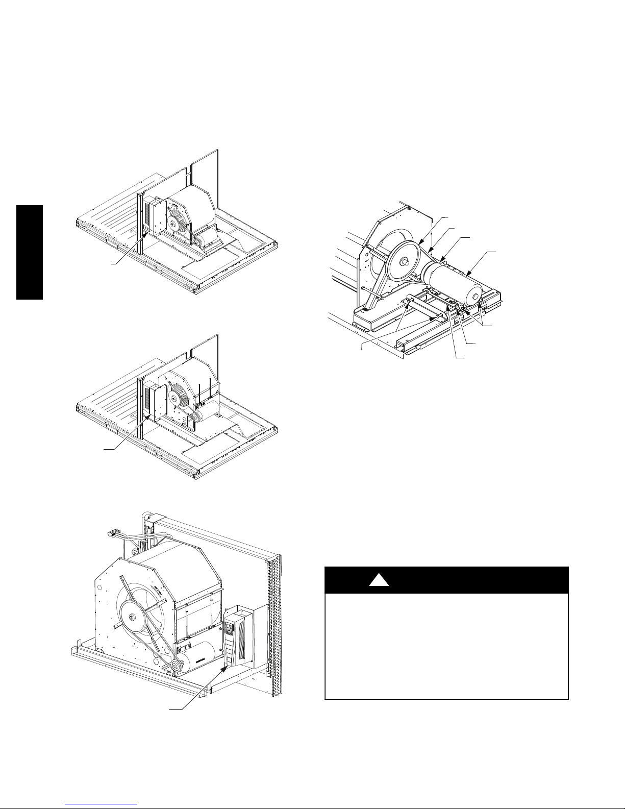
See Figs 10, 11 and 12 for locations of the Variable
Frequency Drive (VFD) as mounted on the various 50HC
models.
VARIABLE
50HC
FREQUENCY
DRIVE (VFD)
Fig. 10 -- VFD Location for size 08--09
VARIABLE
FREQUENCY
DRIVE (VFD)
Fig. 11 -- VFD Location for size 12
C11528
C11529
ADDITIONAL VARIABLE FREQUENCY
DRIVE (VFD) INSTALLATION AND
TROUBLESHOOTING
Additional installation, wiring and troubleshooting
information for the Variable Frequency Drive can be
found in the following manuals: “Variable Frequency
Drive (VFD) Installation, Setup and Troubleshooting
Supplement.”
MOTOR
When replacing the motor, use the following steps. See
Fig. 13.
BLOWER PULLEY
V-B ELT
MOTOR PULLEY
MOTOR
MOTOR MOUNTING
BRACKET BOLTS (4)
JACK BOLT JAM NUT (2)
JACK BOLT (2)
Fig. 13 -- Replacing Belt Driven Motor
Replacing the Motor
Use the following steps to replace the belt--driven motor.
1. Turn off all electrical power to the unit. Use approved
lockout/tagout procedures on all electrical power
sources.
2. Remove cover on motor connection box.
3. Disconnect all electrical leads to the motor.
4. Loosen the two jack bolt jamnuts on the motor
mounting bracket.
5. Turn two jack bolts counterclockwise until motor
assembly moves closer to blower pulley.
6. Remove V--belt from blower pulley and motor pulley.
MOTOR MOUNTING
BRACKET (2)
C12034
VARIABLE
FREQUENCY
DRIVE (VFD)
Fig. 12 -- VFD Location for size 14
C11530
!
CAUTION
EQUIPMENT DAMAGE HAZARD
Failure to follow this CAUTION can result in
premature wear and damage to equipment.
Do not use a screwdriver or a pry bar to pl ace the new
V--belt in the pulley groove. This can cause stress on
the V--belt and the pulley resulting in premature wear
on the V--belt and damage to the pulley.
7. Loosen the four mounting bracket bolts and lock
washers.
8. Remove four bolts, four flat washers, four lock
washers and four nuts attaching the motor mounting
8

plate to the unit. Discard all lock washers.
9. Remove motor and motor mounting bracket from
unit.
10. Remove four bolts, flat washers, lock washers and
single external--tooth lock washer attaching motor to
the motor mounting plate. Discard all lock washers
and external--tooth lock washer.
11. Lift motor from motor mounting plate and set aside.
12. Slide motor mounting band from old motor.
13. Slide motor mounting band onto new motor and set
motor onto the motor mounting plate.
14. Remove variable pitch pulley from old motor and
attach it to the new motor.
15. Inspect variable pitch pulley for cracks and wear.
Replace the pulley if necessary.
16. Secure the pulley to the motor by tightening the
pulley setscrew to the motor shaft.
17. Insert four bolts and flat washers through mounting
holes on the motor into holes on the motor mounting
plate.
18. On one bolt, place a new external--tooth lock washer
between the motor and motor mounting band.
19. Ensure the teeth of the external--tooth lock washer
make contact with the painted ba se of the motor.
This washer is essential for properly grounding motor.
20. Install four new lock washers and four nuts on the
bolts on the bottom of the motor mounting plate.
21. Do Not tighten the mounting bolts at this time.
22. Set new motor and motor mounting bracket back onto
the unit. See Fig. 13.
23. Install four bolts, four flat washers, four new lock
washers and four nuts attaching the motor assembly
to the unit.
24. Do Not tighten the mounting bolts at this time.
25. Install motor drive V--belt to motor pulley and blower
wheel pulley. See CAUTION.
26. Align the motor pulley and blower wheel pulley using
a straight edge. See Fig. 8.
27. Adjust the V--belt tension using adjustment tool.
28. Turn two jac k bolts cl ockwise, moving the motor
assembly away from the blower pulley, increasing the
V--belt tension.
29. Tighten the four bolts securing the motor mounting
brackets to the unit. Torque four bolts to 120 12
in--lbs (14 1.4 Nm).
30. Remove cover on motor c onnection box.
31. Re--connect all electrical leads to the motor and
replace the connection box cover.
32. Re--connect all electrical power to the unit. Remove
lockout tags on all electrical power sources.
33. Start unit and allow to run for a designated period.
34. Shut off unit and make any necessary adjustments to
the V--belt tension or the motor and blower wheel
pulley alignment.
When replacing the motor, also replace the external --tooth
lock washer (star washer) under t he motor mounting base;
this is part of the motor grounding system. Ensure the
teeth on the lock washer are in contact with the motor’s
painted base. Tighten motor mounting bolts to 120 12
in--lbs.
Changing Fan Wheel Speed
Changing fan wheel speed by changing pulleys: The
horsepower rating of the belt is primarily dictated by the
pitch diameter of the smaller pulley in the drive system
(typically the motor pulley in these units). Do not install a
replacement motor pulley with a smaller pitch diameter
than provided on the original factory pulley. Change fan
wheel speed by changing the fan pulley (larger pitch
diameter to reduce wheel speed, smaller pitch diameter to
increase wheel speed) or select a new system (both
pulleys and matching belt).
Before changing pulleys to increase fan wheel speed,
check the fan performance at the target speed and airflow
rate to determine new motor loading (bhp). Use the fa n
performance tables or use the Packaged Rooftop Builder
software program. Confirm that the motor in this unit is
capable of operating at the new operating condition. Fan
shaft loading increases dramatically as wheel speed is
increased.
To reduce vibration, replace the motor’s adjustable pitch
pulley with a fixed pitch pulley (after the final airflow
balance adjustment). This will reduce the amount of
vibration generated by the motor/belt--drive system.
50HC
9

Decel
(2203)
Accel
(2202)
Decel
Accel/
(2201)
Fcn
Stop
(2102)
Fcn
Start
(2101)
Freq
(2606)
Switch
Max
Freq
(2008)
Min
Freq
(2007)
REMOTE VFD KEYPAD REFERENCE
Table 4 – SRT Unit VFD Parameters — 50HC** 08--12
Motor
Max
Relay
Const
Const
Const
Const
Nom
Nom
Nom
Nom
Amps
Out 3
Speed 3
Speed 2
Speed 1
Speed Sel
HP
RPM
Freq
Amps
(2003)
(1403)
(1204)
(1203)
(1202)
(1201)
(9909)
(9908)
(9907)
(9906)
6.7 0Hz 60Hz 4kHz Auto Ramp Not Sel 30 sec 30 sec
3.3 0Hz 60Hz 4kHz Auto Ramp Not Sel 30 sec 30 sec
3.6 0Hz 60Hz 4kHz Auto Ramp Not Sel 30 sec 30 sec
9.1 0Hz 60Hz 4kHz Auto Ramp Not Sel 30 sec 30 sec
4.1 0Hz 60Hz 4kHz Auto Ramp Not Sel 30 sec 30 sec
4.4 0Hz 60Hz 4kHz Auto Ramp Not Sel 30 sec 30 sec
Alarm
Alarm
Alarm
Alarm
Alarm
16 FLT/
16 FLT/
16 FLT/
16 FLT/
Alarm
16 FLT/
16 FLT/
4.8 0Hz 60Hz 4kHz Auto Ramp Not Sel 30 sec 30 sec
10.6 0Hz 60Hz 4kHz Auto Ramp Not Sel 30 sec 30 sec
Alarm
Alarm
16 FLT/
16 FLT/
6.2 0Hz 60Hz 4kHz Auto Ramp Not Sel 30 sec 30 sec
13.5 0Hz 60Hz 4kHz Auto Ramp Not Sel 30 sec 30 sec
Alarm
16 FLT/
5.6 0Hz 60Hz 4kHz Auto Ramp Not Sel 30 sec 30 sec
Alarm
Alarm
16 FLT/
16 FLT/
7.4 0Hz 60Hz 4kHz Auto Ramp Not Sel 30 sec 30 sec
15.6 0Hz 60Hz 4kHz Auto Ramp Not Sel 30 sec 30 sec
Alarm
16 FLT/
6.9 0Hz 60Hz 4kHz Auto Ramp Not Sel 30 sec 30 sec
Alarm
Alarm
16 FLT/
16 FLT/
50HC
(9905)
Volt age
Par t
Motor
Number
ABB Part Number Description
Par t
VFD
Number
HK30WA352 ACH550--- U0--- 012A---2 1.7 HP 230V HD56FR233 230 5.8 60Hz 1725 1.7 DI 2 ,3 40Hz 60Hz 60Hz
HK30WA356 A CH 5 5 0 --- U 0 --- 0 6 A 9 --- 4 1.7 HP 460V HD56FR463 460 2.9 60Hz 1725 1.7 DI 2,3 40Hz 60Hz 60Hz
HK30WA360 A CH 5 5 0 --- U 0 --- 0 3 A 9 --- 6 1.7 HP 575V HD56F R 579 575 3.1 60Hz 1725 1.7 DI 2,3 40Hz 60Hz 60Hz
HK30WA352 ACH550--- U0--- 012A---2 2.4 HP 230V HD56FE653 230 7.9 60Hz 1725 2.4 DI 2,3 40Hz 60Hz 60Hz
HK30WA356 A CH 5 5 0 --- U 0 --- 0 6 A 9 --- 4 2.4 HP 460V HD56F E653 460 3.6 60Hz 1725 2.4 DI 2,3 40Hz 60Hz 60Hz
HK30WA360 A CH 5 5 0 --- U 0 --- 0 3 A 9 --- 6 2.4 HP 575V HD56F E577 575 3.8 60Hz 1725 2.4 DI 2,3 40Hz 60Hz 60Hz
HK30WA352 ACH550--- U0--- 012A---2 2.9 HP 230V HD58FE654 230 9.2 60Hz 1725 2.9 DI 2,3 40Hz 60Hz 60Hz
HK30WA356 A CH 5 5 0 --- U 0 --- 0 6 A 9 --- 4 2.9 HP 460V HD58F E654 460 4.2 60Hz 1725 2.9 DI 2,3 40Hz 60Hz 60Hz
HK30WA353 ACH550--- U0--- 017A---2 3.7 HP 230V HD60FE656 230 11.7 60Hz 1725 3.7 DI 2,3 40Hz 60Hz 60Hz
10
HK30WA357 A CH 5 5 0 --- U 0 --- 0 8 A 8 --- 4 3.7 HP 460V HD60F E656 460 5.4 60Hz 1725 3.7 DI 2,3 40Hz 60Hz 60Hz
HK30WA361 A CH 5 5 0 --- U 0 --- 0 6 A 1 --- 6 3.7 HP 575V HD58F E577 575 4.9 60Hz 1725 3.7 DI 2,3 40Hz 60Hz 60Hz
HK30WA354 ACH550--- U0--- 024A---2 5.3 HP 230V HD60FK658 230 13.6 60Hz 1740 5.3 DI 2,3 40Hz 60Hz 60Hz
HK30WA358 ACH550--- U0--- 012A---4 5.3 HP 460V HD60FK658 460 6.4 60Hz 1740 5.3 DI 2,3 40Hz 60Hz 60Hz
HK30WA362 A CH 5 5 0 --- U 0 --- 0 9 A 0 --- 6 5.3 HP 575V HD60F E576 575 6.0 60Hz 1725 5.3 DI 2,3 40Hz 60Hz 60Hz

Decel
(2203)
Accel
(2202)
Decel
Accel/
(2201)
Fcn
Stop
(2102)
Fcn
Start
(2101)
Freq
(2606)
Switch
Max
Freq
(2008)
Min
Freq
(2007)
50HC
REMOTE VFD KEYPAD REFERENCE (CONT)
Max
Relay
Const
Const
Const
Const
Nom
Nom
Motor
Table 5 – SRT Unit VFD Parameters — 50HC** 14
Nom
Nom
Amps
Out 3
Speed 3
Speed 2
Speed 1
Speed Sel
HP
RPM
Freq
Amps
(2003)
(1403)
(1204)
(1203)
(1202)
(1201)
(9909)
(9908)
(9907)
(9906)
9.1 0Hz 60Hz 4kHz Auto Ramp Not Sel 30 sec 30 sec
4.1 0Hz 60Hz 4kHz Auto Ramp Not Sel 30 sec 30 sec
4.4 0Hz 60Hz 4kHz Auto Ramp Not Sel 30 sec 30 sec
Alarm
Alarm
16 FLT/
Alarm
16 FLT/
16 FLT/
4.8 0Hz 60Hz 4kHz Auto Ramp Not Sel 30 sec 30 sec
10.6 0Hz 60Hz 4kHz Auto Ramp Not Sel 30 sec 30 sec
Alarm
Alarm
16 FLT/
16 FLT/
6.2 0Hz 60Hz 4kHz Auto Ramp Not Sel 30 sec 30 sec
13.5 0Hz 60Hz 4kHz Auto Ramp Not Sel 30 sec 30 sec
Alarm
16 FLT/
5.6 0Hz 60Hz 4kHz Auto Ramp Not Sel 30 sec 30 sec
Alarm
Alarm
16 FLT/
16 FLT/
9.9 0Hz 60Hz 4kHz Auto Ramp Not Sel 30 sec 30 sec
19.7 0Hz 60Hz 4kHz Auto Ramp Not Sel 30 sec 30 sec
Alarm
16 FLT/
8.7 0Hz 60Hz 4kHz Auto Ramp Not Sel 30 sec 30 sec
Alarm
Alarm
16 FLT/
16 FLT/
(9905)
Volt age
Par t
Motor
Number
ABB Part Number Description
Par t
VFD
Number
HK30WA352 ACH550--- U0--- 012A---2 2.4 HP 230V HD56FE653 230 7.9 60Hz 1725 2.4 DI 2,3 40Hz 60Hz 60Hz
HK30WA356 A CH 5 5 0 --- U 0 --- 0 6 A 9 --- 2 2.4 HP 460V HD56F E653 460 3.6 60Hz 1725 2.4 DI 2,3 40Hz 60Hz 60Hz
HK30WA360 A CH 5 5 0 --- U 0 --- 0 3 A 9 --- 6 2.4 HP 575V HD56F E577 575 3.8 60Hz 1725 2.4 DI 2,3 40Hz 60Hz 60Hz
HK30WA352 ACH550--- U0--- 012A---2 2.9 HP 230V HD58FE654 230 9.2 60Hz 1725 2.9 DI 2,3 40Hz 60Hz 60Hz
HK30WA356 A CH 5 5 0 --- U 0 --- 0 6 A 9 --- 4 2.9 HP 460V HD58F E654 460 4.2 60Hz 1725 2.9 DI 2,3 40Hz 60Hz 60Hz
HK30WA353 ACH550--- U0--- 017A---2 3.7 HP 230V HD60FE656 230 11.7 60Hz 1725 3.7 DI 2,3 40Hz 60Hz 60Hz
HK30WA357 A CH 5 5 0 --- U 0 --- 0 8 A 8 --- 4 3.7 HP 460V HD60F E656 460 5.4 60Hz 1725 3.7 DI 2,3 40Hz 60Hz 60Hz
HK30WA361 A CH 5 5 0 --- U 0 --- 0 6 A 1 --- 6 3.7 HP 575V HD58F E577 575 4.9 60Hz 1725 3.7 DI 2,3 40Hz 60Hz 60Hz
HK30WA354 ACH550--- U0--- 024A---2 5.0 HP 230V HD60FL 657 230 17.1 60Hz 1760 5 DI 2,3 40Hz 60Hz 60Hz
11
HK30WA358 ACH550--- U0--- 012A---4 5.0 HP 460V HD60FL 657 460 8.6 60Hz 1760 5 DI 2,3 40Hz 60Hz 60Hz
HK30WA362 A CH 5 5 0 --- U 0 --- 0 9 A 0 --- 6 5.0 HP 575V HD60F K577 575 7.6 60Hz 1745 5 DI 2,3 40Hz 60Hz 60Hz
COOLING
!
WARNING
UNIT OPERATION AND SAFETY HAZARD
Failure to follow this warning could cause personal
injury, death and/or equipment damage.
This system uses PuronR refrigerant which has
higher pressures than R--22 and other refrigerants. No
other refrigerant may be used in this system. Gauge
set, hoses, and recovery system must be designe d to
handle Puron refrigerant. If unsure about equipment,
consult the equipment manufacturer.
Condenser Coil
The condenser coil is fabricated with round tube coppe r
hairpins and plate fins of various materials and/or coatings
50HC
(see Model Number Format in the Appendix to identify
the materials provided in this unit). The coil may be
one--row or composite--type two--row. Composite t wo--row
coils are two single--row coils fabricated with a single
return bend end tubesheet.
Condenser Coil Maintenance and Cleaning
Recommendation
Routine cleaning of coil surfaces is essential to maintain
proper operation of the unit. Elimination of contamination
and removal of harmful residues will greatly increase the
life of the coil and extend the life of the unit. The
following maintenance and cleaning procedures are
recommended as part of the routine maintenance activities
to extend the life of the coil.
Routine Cleaning of Coil Surfaces
Periodic cleaning with TotalineR environmental ly sound
coil cleaner is essential to extend the life of coils. This
cleaner is available from Replacement Components
Division as part number P902--0301 for a one gallon
container, and part number P902--0305 for a 5 gallon
container. It is recommended that all coils, including
standard aluminum, pre--coated, copper/copper or
E--coated coils be cleaned with the Totaline
environmentally sound coil cleaner as described below.
Coil cleaning should be part of the unit’s regularly
scheduled maintenance proc edures to ensure long life of
the coil. Failure to clean the coils may result in reduced
durability in the environment.
Avoid use of:
S coil brighteners
S acid cleaning prior to painting
S high pressure washers
S poor quality water for cleaning
Totaline environmentally sound coil cleaner is
nonflammable, hypo allergenic, non bacterial, and a
USDA accepted biodegradable agent that will not harm
the coil or surrounding components such as electrical
wiring, painted metal surfaces, or insulation. Use of
non--recommended coil cleaners is strongly discouraged
since coil and unit durability could be affected.
One--Row Coil
Wash coil with commercial coil cleaner. It is not
necessary to remove top panel.
Two--Row Coils
Remove Surface Loaded Fibers
Surface loaded fibers or dirt should be removed with a
vacuum cleaner. If a vacuum cleaner is not available, a
soft non--metallic bristle brush may be used. In either
case, the tool should be applied in the direction of the fins.
Coil surfaces can be easily damaged (fin edges can be
easily bent over and damage to the coating of a protected
coil) if the tool is applied across the fins.
NOTE: Use of a water stream, such as a garden hose,
against a surface loaded coil will drive the fibers and dirt
into the coil. This will make cleaning efforts more
difficult. Surface loaded fibers must be completely
removed prior to using low velocity clean water rinse.
Periodic Clean Water Rinse
A periodic clean water rinse is very beneficial for coils
that are appli ed in coastal or industrial e nvironments.
However, it is very important that the water rinse is made
with a very low velocity water stream to avoid damaging
the fin edges. Monthly cleaning as described below is
recommended. Rinsing coils in the opposite direction of
airflow is recommende d.
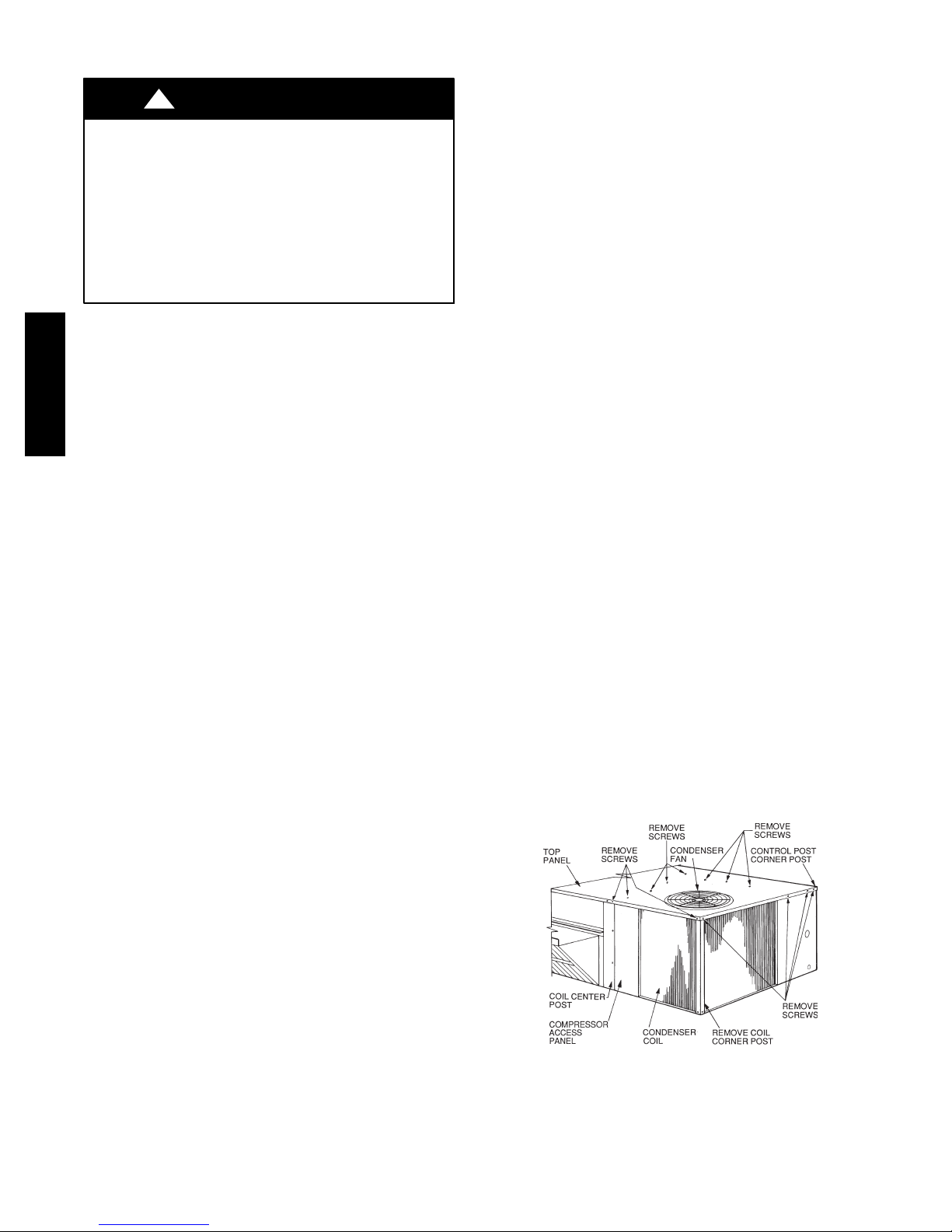
Clean coil as follows:
1. Turn off unit power, tag disconnect.
2. Remove top panel screws on condenser end of unit.
3. Remove condenser coil corner post. See Fig. 14. To
hold top panel open, place coil corner post between
top panel and center post. See Fig. 15.
C08205
Fig. 14 -- Cleaning Condenser Coil
12
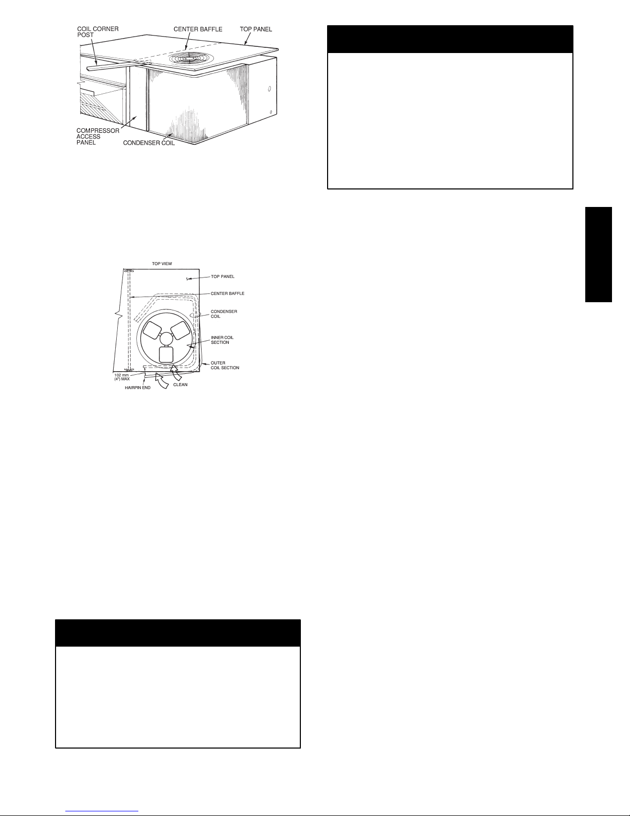
Fig. 15 -- Propping Up Top Panel
4. Remove screws securing coil to compressor plate and
compressor access panel.
5. Remove fastener holding coil sections together at return end of condenser coil. Carefully separate the outer coil section 3 to 4 in. from the inner coil section.
See Fig. 16.
Fig. 16 -- Separating Coil Sections
6. Use a water hose or other suitable equipment to flush
down between t he 2 coil sections to remove dirt and
debris. Clean the outer surfaces with a stiff brush in
the normal manne r.
7. Secure inner and outer coil rows together with a
field--supplied fastener.
8. Reposition the outer coil section and remove the coil
corner post from between the top panel and center
post. Reinstall the coil corner post and replace all
screws.
Totaline Environmentally Sound Coil Cleaner
Application Equipment
S 2--1/2 gallon garden sprayer
S Water rinse with low velocity spray nozzle
CAUTION
UNIT DAMAGE HAZARD
Failure to follow this caution may result in reduced
unit performance or unit shutdown.
High velocity water from a pressure washer, garden
hose, or compressed air should never be used to
clean a coil. The force of the water or air jet will
bend the fin edges and increa se airside pressure drop.
C08206
C08207
CAUTION
UNIT DAMAGE HAZARD
Failure to follow this caution may result in accelerated
corrosion of unit parts.
Harsh chemicals, household bleach or acid or basic
cleaners should not be used to clean outdoor or indoor
coils of any kind. These cleaners can be very difficult
to rinse out of the coil and can accelerate corrosion at
the fin/tube interface where dissimilar materials are in
contact. If there is dirt below the surface of the coil,
use the Totaline environmentally sound coil cleaner.
Totaline Environmentally Sound Coil Cleaner
Application Instructions
1. Proper eye protection such as safety glasses is recommended during mixing and application.
2. Remove all surface loaded fibers and dirt with a vacuum cleaner as described above.
3. Thoroughly wet finned surfaces with clean water and
a low ve locity garden hose, being careful not to bend
fins.
4. Mix Totaline environmentally sound coil cleaner in a
2--1/2 gallon garden sprayer according to the instructions included with the cleaner. The optimum solution
temperature is 100_F.
NOTE: Do NOT USE water in excess of 130_F, as the
enzymatic activity will be destroyed.
5. Thoroughly apply Totaline environmentally sound
coil cleaner solution to all coil surfaces including
finned area, tube sheets and coil headers.
6. Hold garden sprayer nozzle close to finned areas and
apply cleaner with a vertical, up--and--down motion.
Avoid spraying in horizontal pattern to minimize potential for fin damage.
7. Ensure cleaner thoroughly penetrates dee p into finned
areas.
8. Interior and exterior finned areas must be thoroughly
cleaned.
9. Finned surfaces should remain wet with cleaning
solution for 10 minutes.
10. Ensure surfaces are not allowed to dry before rinsing.
Reapplying cleaner as needed to ensure 10--minute
saturation is achieved.
11. Thoroughly rinse all surfaces with low velocity clean
water using downward rinsing motion of water spray
nozzle. Protect fins from damage from the spray
nozzle.
Evaporator Coil
Cleaning the Evaporator Coil
1. Turn unit power off. Install lockout tag. Remove
evaporator coil access panel.
2. If economizer or two--position damper is installed, remove economizer by disconnecting Molex plug and
removing mounting screws.
3. Slide filters out of unit.
50HC
13
4. Clean coil using a commercial coil cleaner or dishwasher detergent in a pressurized spray canister. Wash
both sides of coil and flush with clean water. For best
results, back--flush toward return--air section to remove foreign material. Flush condensate pan after
completion.
5. Reinstall economizer and filters.
6. Reconnec t wiring.
7. Replace access panels.
THERMOSTATIC EXPANSION
VALVE (TXV)
All 50HC’s have a factory installed nonadjustable
thermostatic expansion valve (TXV). The TXV will be a
bi-flow, bleed port expansion valve with an external
equalizer. TXVs are specifically designed to operate with
PuronR or R-22 refrigerant, use only factory authorized
TXVs. Do not interchange Puron and R-22 TXVs.
50HC
TXV Operation
The TXV is a metering device that is used in air
conditioning and heat pump systems to adjust to the
changing load conditions by maintaining a preset
superheat temperature at the outlet of the evaporator coil.
6. Install the new TXV using a wrench and an additional
wrench on connections to prevent damage to tubing
while attaching TXV to distributor.
7. Attach the equalizer tube to the suction line. If the
coil has mechanical a connection, then use a wrench
and an additional wrench on connections to prevent
damage. If the coil has a brazed connection, use a file
or a tubing cutter to remove the mechanical flare nut
from the equalizer line. Then use a new coupling to
braze the equalizer line to t he stub (previous equalizer
line) in suction line.
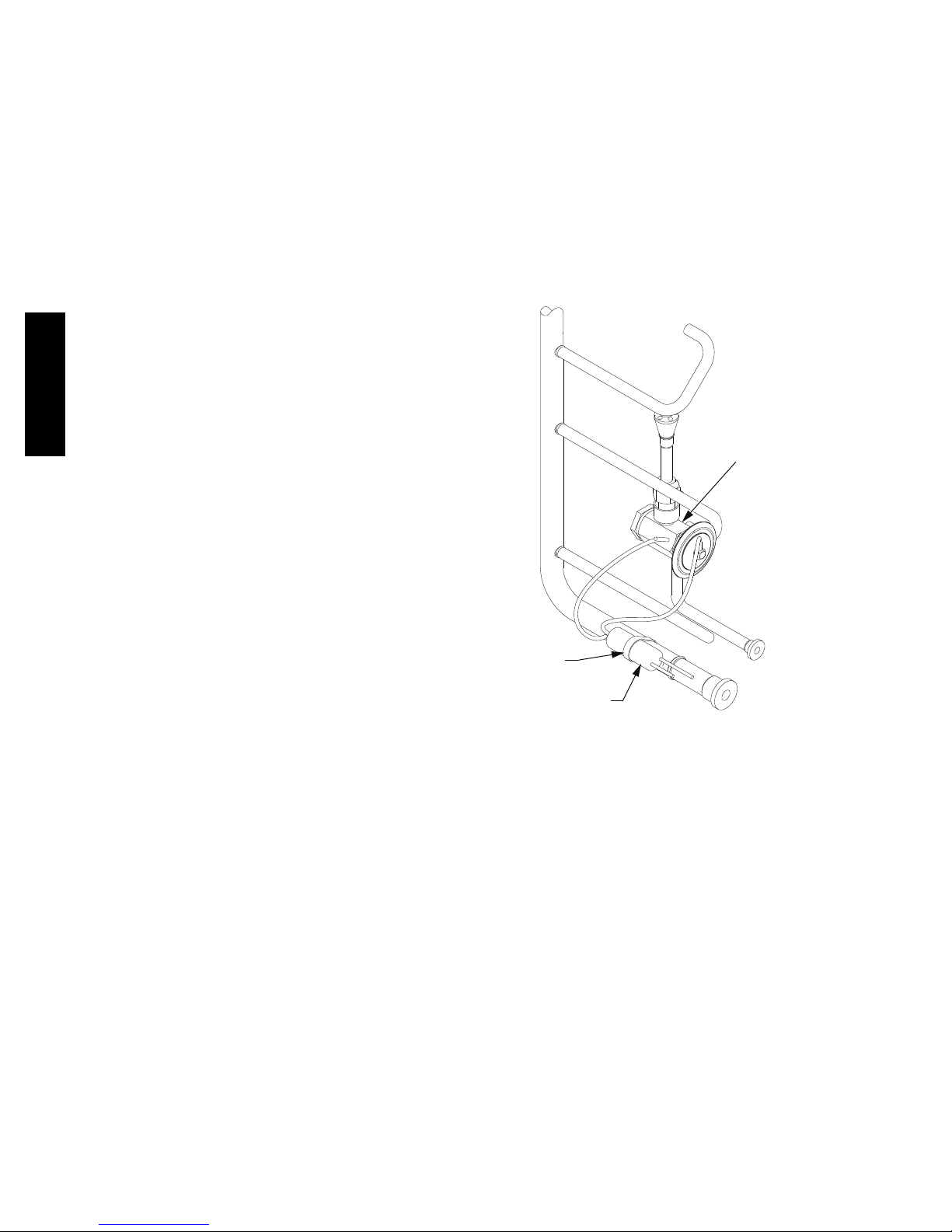
8. Attach TXV bulb in the same location where the original (in the sensing bulb indent) was when it was removed, using the supplied bulb clamps. See Fig. 17.
THERMAL EXPANSION
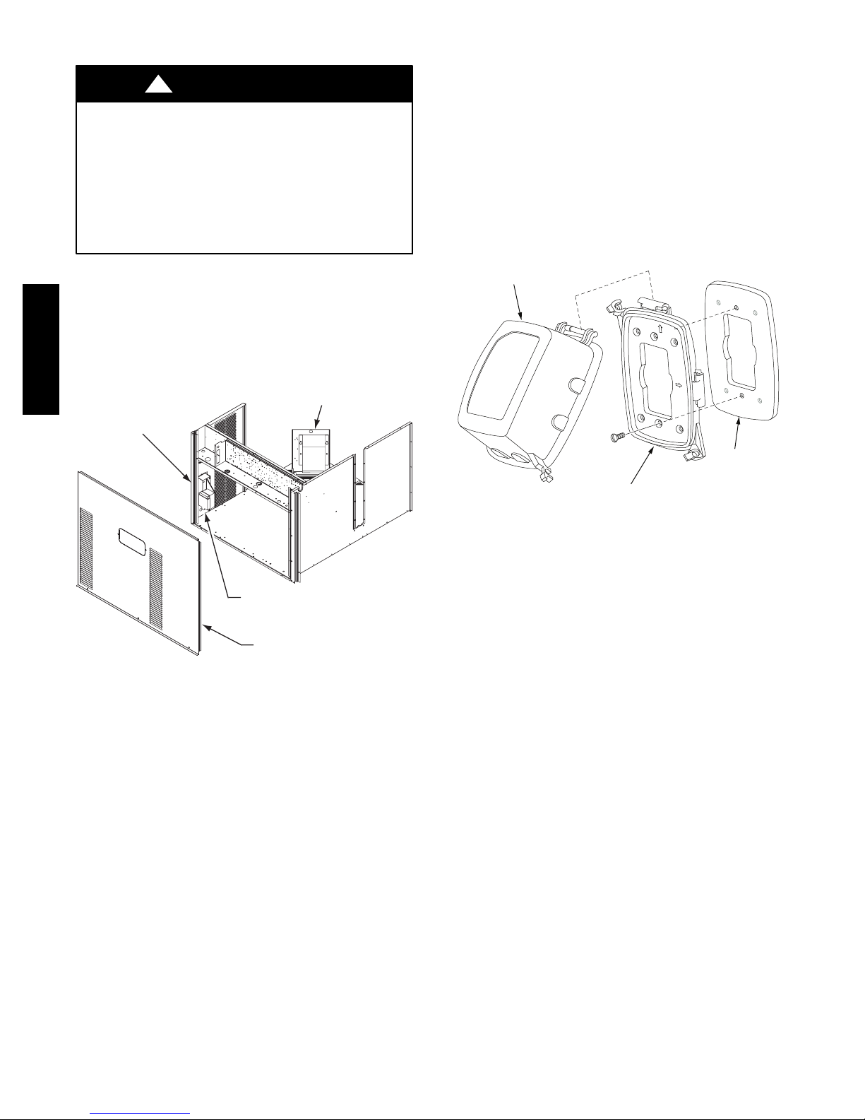
(TXV) VALVE
The volume of refrigerant metered through the valve seat
is dependent upon the following:
1. Superheat temperature is sensed by cap tube sensing
bulb on suction tube at outlet of evaporator coil. This
temperature is converted into pressure by refrigerant
in the bulb pushing downward on the diaphragm
which opens the valve using the push rods.
2. The suction pressure at the outlet of the evaporator
coil is transferred through the e xternal equalizer tube
to the underside of the diaphragm.
3. The pin is spring loaded, which exerts pressure on the
underside of the diaphragm. Therefore, the bulb pressure works against the spring pressure and evaporator
suction pressure to open the valve. If the load increases, the temperature increases at the bulb, which
increases the pressure on the top side of the diaphragm. This opens the valve and increases the flow
of refrigerant. The increased refrigerant flow causes
the leaving evaporator temperature to decrease. This
lowers the pressure on the diaphragm and closes the
pin. The refrigerant flow is effectively stabilized to
the load demand with negligible change in superheat.
Replacing TXV
CLAMP
TXV SENSING
BULB
SENSING BULB INSULATION REMOVED FOR CLARITY
C10372
Fig. 17 -- TXV Valve and Sensing Bulb Location
9. Route equalizer tube through suction connection
opening (large hole) in fitting panel and install fitting
panel in place.
10. Sweat the inlet of TXV marked “IN” to the liquid
line. Avoid excessive heat which could damage the
TXV valve. Use quenching cloth when applying heat
anywhere on TXV.
Refrigerant System Pressure Access Ports
1. Recover refrigerant.
2. Remove TXV support clamp using a 5/l6-in. nut
driver.
3. Remove TXV using a wrench and an additional
wrench on connections to prevent damage to tubing.
4. Remove equalizer tube from suction line of coil. Use
file or tubing cutter to cut brazed equalizer line
approximately 2 i nches above suction tube.
5. Remove bulb from vapor tube inside cabinet.
There are two access ports in the system -- on the suction
tube near the compressor and on the discharge tube near
the compressor. These are brass fittings with black plastic
caps. The hose connection fittings are standard 1/4 SAE
male flare couplings.
The brass fittings are two-- piece High Flow valves, with a
receptacle base brazed to the tubing and an integral
spring--closed check valve core screwed into the base. See
Fig. 18. This check valve is permanently assembled into
this core body and cannot be serviced separately; replace
14
the entire core body if necessary. Service tools are
available from RCD that allow the replacement of the
check val ve core without having to recover the entire
system refrigerant charge. Apply compressor refrigerant
oil to the check valve core’s bottom o--ring. Install the
fitting body with 96 10 in--lbs (10.85 1.1 Nm) of
torque; do not overtighten.
PURONR (R--410A) REFRIGERANT
This unit is designed for use with Puron (R-- 410A)
refrigerant. Do not use any other refrigerant in this
system. Puron (R--410A) refrigerant is provided in pink
(rose) colored cylinders.
Puron (R--410A) refrigerant is provided in pink (rose)
colored cylinders. These cylinders are available with and
without dip tubes; cylinders with dip tubes will have a
label indicating this feature. For a cylinder with a dip
tube, place the cylinder in the upright position (access
valve at the t op) when removing liquid refrigerant for
charging. For a cylinder without a dip tube, invert the
cylinder (access valve on the bottom) when removing
liquid refrigerant.
Because Puron (R--410A) refrigerant is a blend, it is
strongly recommended that refrigerant always be removed
from the cylinder as a liquid. Admit liquid refrigerant into
the system in the discharge line. If adding refrigerant into
the suction line, use a commercial metering/expansion
device at the gauge manifold; remove liquid from the
cylinder, pass it through the metering device at the gauge
set and then pass it into the suction line as a vapor. Do not
remove Puron (R--410A) refrigerant from the cylinder as a
vapor.
Refrigerant Charge
No Charge
Use standard evacuating techniques. After evacuating
system, weigh in the specified amount of refrigerant.
Low--Charge Cooling
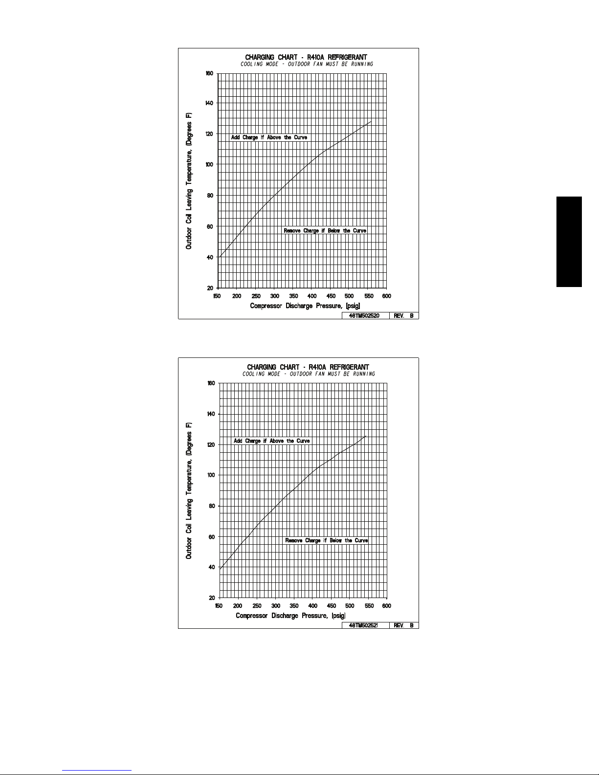
Using Cooling Charging Charts, Fig. 19 through Fig. 26,
vary refrigerant until the conditions of the appropriate
chart are met. Note the charging charts are different from
type normally used. Charts are based on charging the units
to the correct sub--cooling for the various operating
conditions. Accurate pressure gauge and temperature
sensing device are required. Connect the pressure gauge to
the service port on the liquid line. Mount the temperature
sensing device on the liquid line and insulate it so that
outdoor ambient temperature does not affect the reading.
Indoor--air cfm must be within the normal operating range
of the unit.
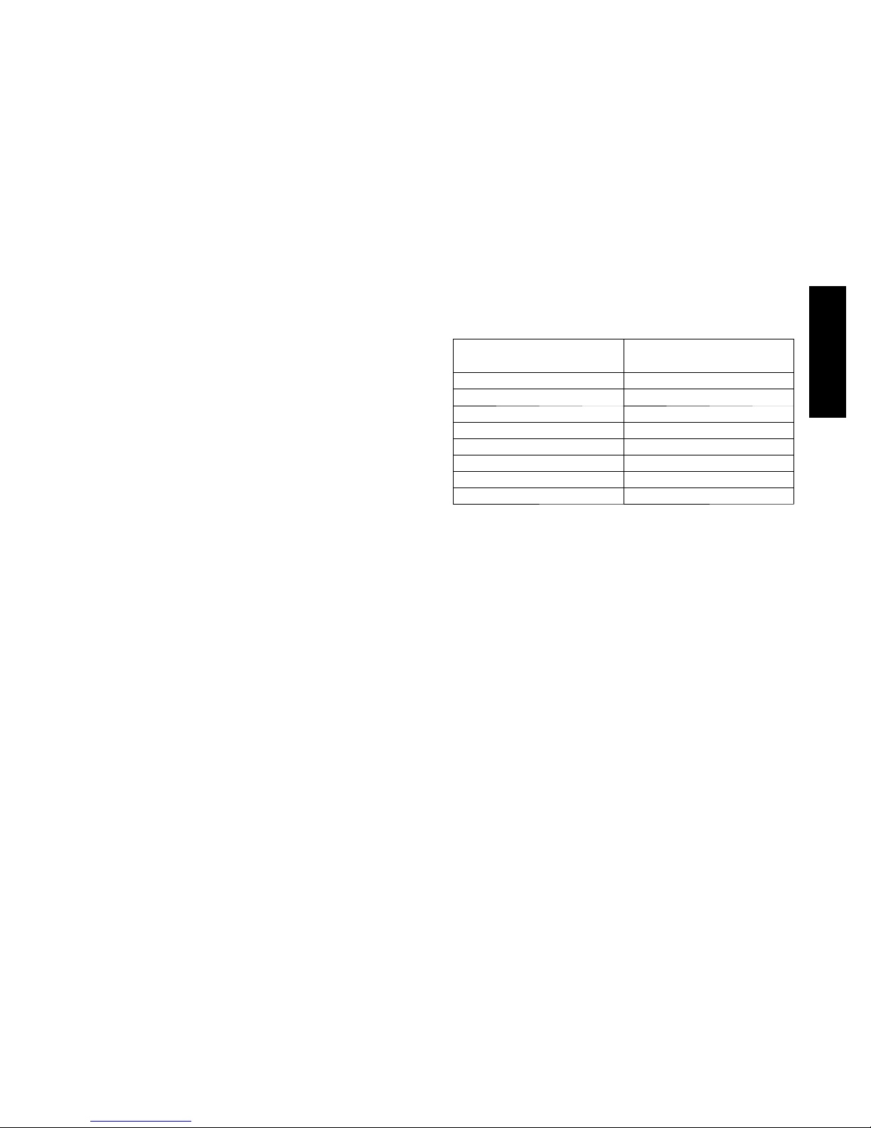
SIZE DESIGNATION NOMINAL TONS
04 3
05 4
06 5
07 6
08 7.5
09 8.5
12 10
14 12.5
REFERENCE
EXAMPLE:
Model 50HC*A04
Outdoor Temperature 85_F(29_C)..................
Suction Pressure 140 psig (965 kPa).................
Suction Temperature should be 60_F(16_C)..........
50HC
Amount of refrigerant charge is listed on the unit’s
nameplate. Refer to Carrier GTAC2-- 5 Charging,
Recovery, Recycling and Reclamation training manual
and the following procedures.
Unit panels must be in place when unit is operating during
the charging procedure.
Using Cooling Charging Charts
Take the outdoor ambient temperature and read the liquid
pressure gauge. Refer to chart to determine what liquid
temperature should be. If liquid temperature is low, add
refrigerant. If liquid temperature is high, carefully recover
some of the charge. Recheck the liquid pressure as charge
is adjusted.
15
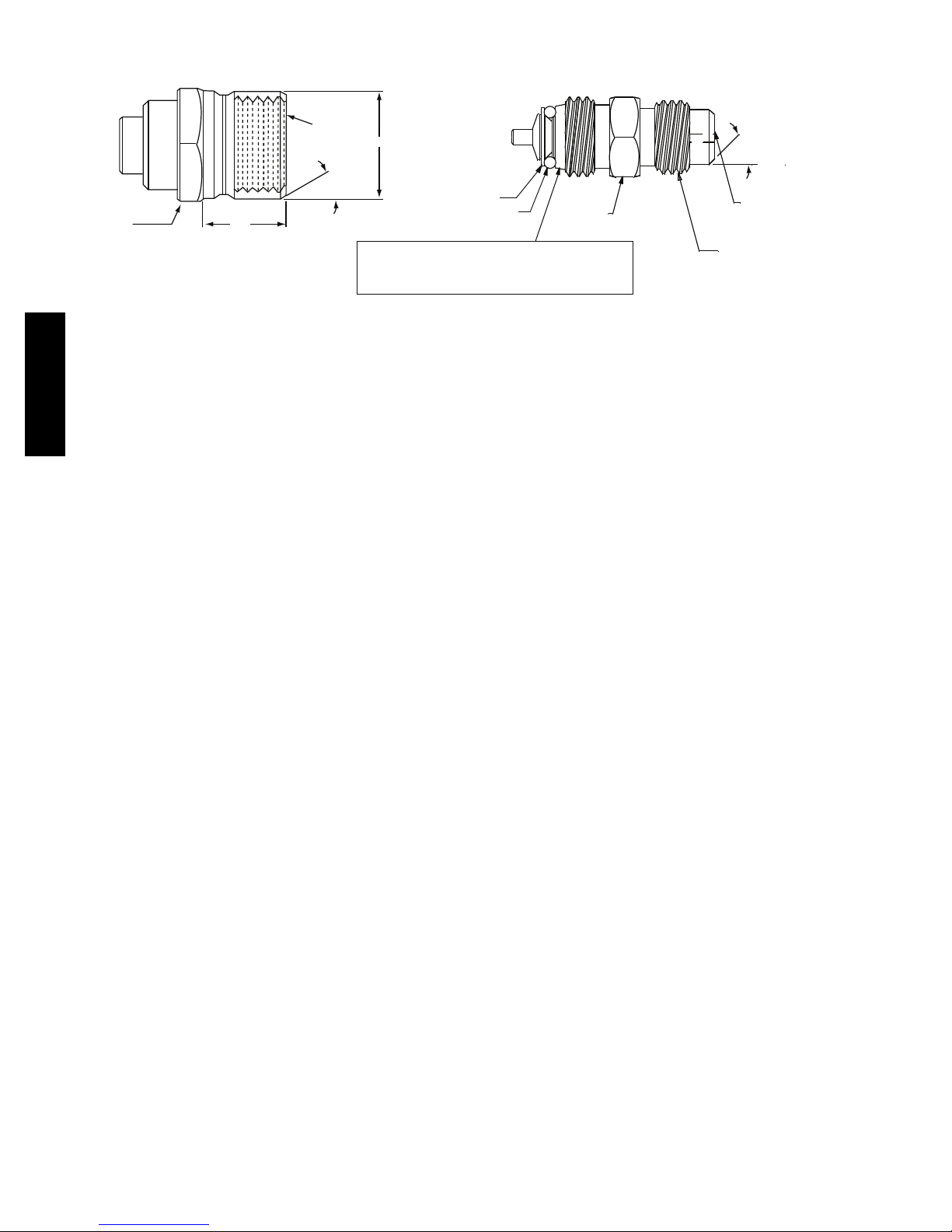
SEAT
CORE
(Part No. EC39EZ067)
1/2-20
5/8” HEX
UNF RH
.47
0.596
o
30
WASHER
O-RING
This surface provides a metal to metal seal when
1/2” HEX
o
45
DEPRESSOR PER ARI 720
+.01/-.035
FROM FACE OF BODY
7/16-20 UNF RH
torqued into the seat. Appropriate handing is
required to not scratch or dent the surface.
C08453
Fig. 18 -- CoreMax Access Port Assembly
50HC
16
COOLING CHARGING CHARTS
50HC
Fig. 19 -- Cooling Charging Charts -- 3 Ton
C14053
C14054
Fig. 20 -- Cooling Charging Chart -- 4 Ton
17
COOLING CHARGING CHARTS (cont.)
50HC
Fig. 21 -- Cooling Charging Chart -- 5 Ton
CHARGING CHART - R410A REFRIGERANT
160
)
F
seerge
140
D
(
,erutare
120
p
me
100
T
gniv
a
eL li
80
o
C r
60
o
o
d
t
uO
40
20
150 200 250 300 350 400 450 500 550 600
COOLING MODE-ALL OUTDOOR FANS MUST BE RUNNING
Add Charge if Above the Curve
Remove Charge if Below the Curve
Compressor Discharge Pressure, [psig]
48TM502680 rev. -
Fig. 22 -- Cooling Charging Chart -- 6 Ton
C14055
C14056
18
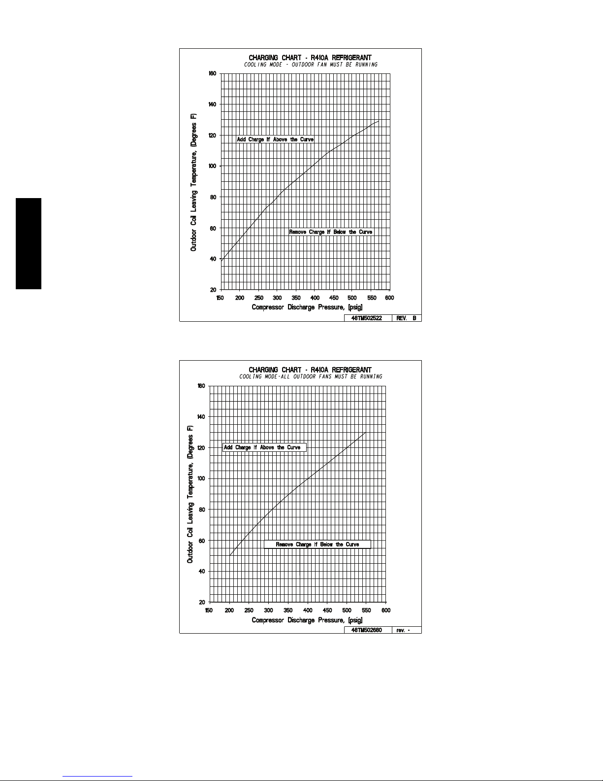
COOLING CHARGING CHARTS (cont.)
CHARGING CHART - R410A REFRIGERANT
160
)F
s
eergeD( ,erutare
140
120
pmeT
100
gniv
aeL
80
lioC roodt
COOLING MODE-ALL OUTDOOR FANS MUST BE RUNNING
Add Charge if Above the Curve
60
Remove Charge if Below the Curve
uO
40
20
150 200 250 300 350 400 450 500 550 600
Compressor Discharge Pressure, [psig]
Fig. 23 -- Cooling Charging Chart -- 7.5 Ton
CHARGING CHART - R410A REFRIGERANT
160
)
F seergeD( ,erutare
140
120
pme
100
T
gniv
a
eL
80
l
ioC
roodt
60
u
O
40
COOLING MODE-ALL OUTDOOR FANS MUST BE RUNNING
Add Charge if Above the Curve
Remove Charge if Below the Curve
50HC
48TM502681 rev. -
C14059
20
150 200 250 300 350 400 450 500 550 600
Compressor Discharge Pressure, [psig]
48TM502682 rev. -
C14060
Fig. 24 -- Cooling Charging Chart -- 8.5 Ton
19
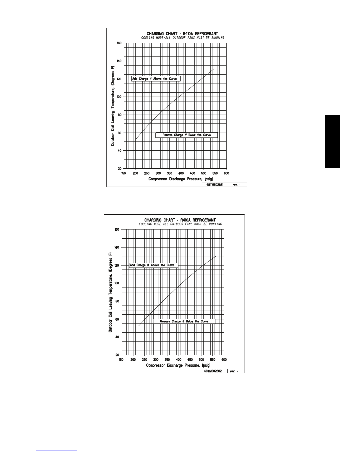
COOLING CHARGING CHARTS (cont.)
50HC
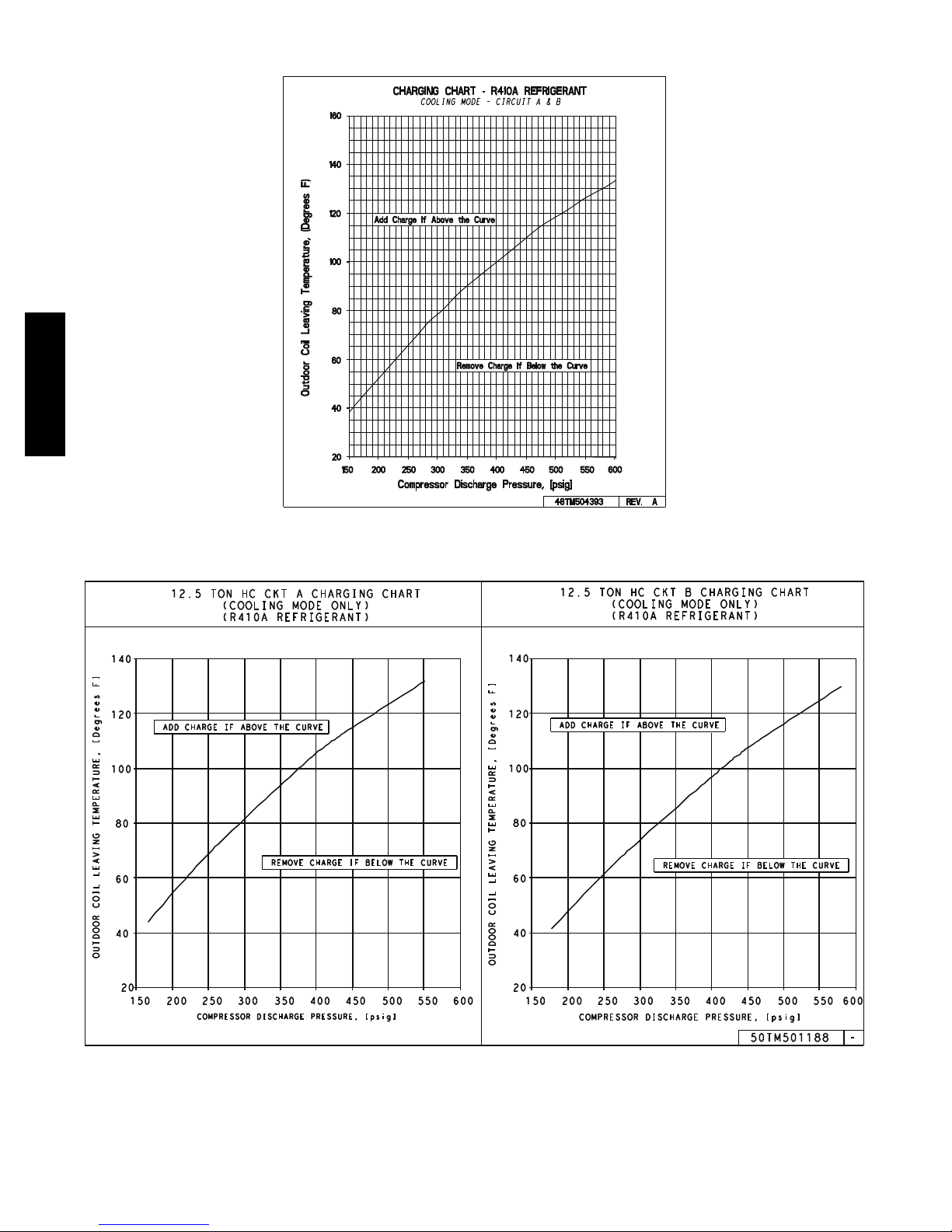
Fig. 25 -- Cooling Charging Chart -- 10 Ton
12.5 TON HC CKT A CHARGING CHART
140
120
100
80
60
40
OUTDOOR COIL LEAVING TEMPERATURE, [Degrees F]
ADD CHARGE IF ABOVE THE CURVE
20
150 200 250 300 350 400 450 500 550 600
(COOLING MODE ONLY)
(R410A REFRIGERANT)
REMOVE CHARGE IF BELOW THE CURVE
COMPRESSOR DISCHARGE PRESSURE, [psig]
12.5 TON HC CKT B CHARGING CHART
140
120
100
80
60
40
OUTDOOR COIL LEAVING TEMPERATURE, [Degrees F]
20
ADD CHARGE IF ABOVE THE CURVE
150 200 250 300 350 400 450 500 550 600
(COOLING MODE ONLY)
(R410A REFRIGERANT)
REMOVE CHARGE IF BELOW THE CURVE
COMPRESSOR DISCHARGE PRESSURE, [psig]
50TM501188
C14057
-
Fig. 26 -- Cooling Charging Chart -- 12.5 Ton -- Circuit A and B
C14058
20
COMPRESSOR
Lubrication
The compressor is charged with the correct amount of oil
at the factory.
CAUTION
INSTALLATION SITE DAMAGE
Failure to follow this caution can result in damage to
equipment location site.
CAUTION
UNIT DAMAGE HAZARD
Failure to follow this caution may result in damage to
components.
The compressor is in a PuronR refrigerant system and
uses a polyolester (POE) oil. Thi s oil is extremely
hygroscopic, meaning it absorbs water readily. POE
oils can absorb 15 times as much water as other oils
designed for HCFC and CFC refrigerants. Avoid
exposure of the oil to the atmosphere.
!
WARNING
FIRE, EXPLOSION HAZARD
Failure to follow this
warning could result in
death, serious personal
injury and/or property
damage.
Never use air or gases containing oxyge n for leak testing
or for operating refrigerant compressors. Pressurized
mixtures of air or gases containing oxygen can lead to an
explosion.
!
WARNING
FIRE, EXPLOSION HAZARD
Failure to follow this
warning could result in
death, serious personal
injury and/or property
damage.
Never use non--certified refrigerants in this product.
Non--certified refrigerants could contain contaminates
that could lea d to unsafe operating conditions. Use
ONLY refrigerants that conform to AHRI Standard
700.
Replacing Compressor
NOTE: Only factory--trained service techni cians should
remove and replace compressor units.
Puron (R--410A) refrigerant contains polyolester
(POE) oil that can damage the roof membrane.
Caution should be taken to prevent POE oil from
spilling onto the roof surface.
The factory also recommends that the suction and
discharge lines be cut with a tubing cutter instead of
using a torch to remove brazed fittings.
Compressor Rotation
CAUTION
EQUIPMENT DAMAGE
Failure to follow this caution can result in equipment
damage.
Scroll compressors can only compress refrigerant if
rotating in the right direction. Reverse rota tion for
extended times can result in internal damage to the
compressor. Scroll compressors are sealed units and
cannot be repaired on site location.
NOTE: When the compressor is rotating in the wrong
direction, the unit makes an elevated level of noise and
does not provide cooling.
On 3--phase units with scroll compressors, it is important
to be certain compressor is rotating in the proper
direction. To determine whe ther or not compressor is
rotating in the proper direction:
1. Connect service gauges to suction and discharge
pressure fittings.
2. Energize the compressor.
3. The suction pressure should drop and the discharge
pressure should rise, as is normal on any star t--up.
NOTE: If the suction pressure does not drop and the
discharge pressure does not rise to normal levels:
4. Note that t he evaporator fan is probably also rotating
in the wrong direction.
5. Turn off power to the unit.
6. Reverse any two of the three unit power leads.
7. Reapply electrical power to the compressor.
8. The suction pressure should drop and the discharge
pressure should rise which is normal for scroll
compressors on start--up.
9. Replace compressor if suction/discharge pressures are
not within specifications for the specific compressor.
The suction and discharge pressure levels should now
move to their normal start--up levels.
50HC
21

Filter Drier
Replace whenever refrigerant system is exposed to
atmosphere. Only use factory specified liquid--line filter
driers with working pressures no less than 650 psig. Do
not install a suction--line filter drier in liquid line. A
liquid--line filter drier designed for use with Puron
refrigerant is required on every unit.
Condenser--Fan Adjustment
Conduit
0.14 in + 0.0 / -0.03
C08448
Fig. 27 -- Condenser Fan Adjustment
1. Shut off unit power supply. Install lockout tag.
2. Remove condenser--fan assembly (grille, m otor, and
fan).
3. Loosen fan hub setscrews.
4. Adjust fan height as shown in Fig. 27.
5. Tighten setscrews.
6. Replac e condenser--fan assembly.
50HC
Troubleshooting Cooling System
Refer to Table 6 for additional troubleshooting topics.
22
Table 6 –
PROBLEM CAUSE REMEDY
Compressor and
Outdoor Fan
Will Not Start.
Compressor Will Not
Start But Outdoor
Fan Runs.
Compressor Cycles
(Other Than
Normally Satisfying
Thermostat).
Compressor Operates
Continuously.
Compressor Makes
Excessive Noise.
Excessive Head
Pressure.
Head Pressure
Too L o w.
Excessive Suction
Pressure.
Suction Pressure
Too L o w.
Power failure. Call power company.
Fuse blown or circuit breaker tripped. Replace fuse or reset circuit breaker. Determine root cause.
Defective thermostat, contactor, transformer,
control relay, or capacitor.
Insufficient line voltage. Determine cause and correct.
Incorrect or f aulty wiring. Check wiring diagram and rewire correctly.
Thermostat setting too high. Lower thermostat setting below room temperature.
High pressure switch tripped. See problem ‘‘Excessive head pressure.’’
Low pressure switch tripped. Check system for leaks. Repair as necessary.
Freeze-up protection thermostat tripped. See problem ‘‘Suction pressure too low.’’
Fault y wiring or loose connectio ns in compressor
circuit.
Compressor motor burned out, seized, or
internal overload open.
Defective run/start capacitor, overload, start
relay.
Onelegof3-phasepowerdead. Replace fuse or reset circuit breaker. Determine cause.
Refrigerant overcharge or undercharge. Recover refrigerant, evacuate system, and recharge to nameplate.
Defective compressor. Replace and determine cause.
Insufficient line voltage. Determine cause and correct.
Blocked outdoor coil or dirty air filter. Clear or clean coil. Replace filter.
Defective run/start capacitor, overload, or start
relay.
Defective thermostat. Replace thermostat.
Faulty outdoor-fan (cooling) or indoor-fan
(heating) motor or capacitor.
Restriction in refrigerant system. Locate restriction and remove.
Dirty air filter. Replace filter.
Unit undersized for load. Decrease load or increase unit size.
Thermostat set too low (cooling). Reset thermostat.
Low refrigerant charge. Locate leak; repair and recharge.
Air in system. Recover refrigerant, replace filter dryer, evacuate system, and
Outdoor coil dirty or restricted. Clean coil or remove restriction.
Compressor rotating in the wrong direction. Reverse the 3-phase power leads as d escribed in
Dirty outside air or return air filter (heating). Replace filter.
Dirty outdoor coil (cooling). Clean coil.
Refrigerant overcharged. Recover excess refrigerant.
Air in system. Recover refrigerant, replace filter dryer, evacuate system, and
Condensing air restricted or air short-cycling. Determine cause and correct.
Low refrigerant charge. Check for leaks; repair and recharge.
Compressor scroll plates defective. Replace compressor.
Restrictioninliquidtube. Remove restriction.
High heat load. Check for source and eliminate.
Compressor scroll plates defective. Replace compressor.
Refrigerant overcharged. Recover excess refrigerant.
Dirty air filter (cooling). Replace filter.
Dirty or heavily iced outdoor coil (heating). Clean outdoor coil. Check defrost cycle operation.
Low refrigerant charge. Check for leaks; repair and recharge.
Metering device or low side restricted. Remove source of restriction.
Insufficient indoor airflow (cooling mode). Increase air quantity. Check filter an d replace if necessary.
Temperature too low in conditioned area. Reset thermostat.
Field-installed filter drier restricted. Rep lace.
Outdoor ambient below 25_F (cooling). Install low-ambient kit.
Outdoor fan motor(s) not operating (heating). Check fan motor operation.
Cooling Troubleshooting
Replace component.
Check wiring and repair or replace.
Determine cause. Replace compressor or allow enough time for
internal overload to cool and reset.
Determine cause and replace defective component.
Determine cause and replace.
Replace.
recharge.
Start-Up.
recharge.
50HC
23
CONVENIENCE OUTLETS
TOP
TOP
TOP
WET LOCATIONS
WET
LOCA
T
I
ONS
!
WARNING
ELECTRICAL O PERATION HAZARD
Failure to follow this warning could result in
personal injury or death.
Units with convenience outlet circuits may use
multiple disconnects. Check convenience outlet for
power status before opening unit for service. Locate
its disconnect switch, if appropriate, and open it.
Tag--out this switch, if necessary.
Convenience Outlets: Two type s of convenience outlets
are offered on 50HC models: Non--powered and
unit--powered. Both types provide a 125VAC
Ground--Fault Circuit--Interrupt (GFCI) duplex receptacle
rated at 15A behind a hinged waterproof access cover,
50HC
located on the end panel of the unit. See Fig. 28.
PWD-CO TRANSFORMER
CONVENIENCE
OUTLET GFCI
2. Loosen the two screws at the GFCI duplex outlet,
1
until approximately
/2-in (13 mm) under screw heads
are exposed.
3. Press the gasket over the screw heads. Slip the
backing plate over the screw heads at the keyhole
slots and align with the gasket; tighten the two screws
until snug (do not over-tighten).
4. Mount the weatherproof cover to the backing plate as
shown in Fig. 29.
5. Remove two slot fillers in the bottom of the cover to
permit service tool cords to exit the cover.
6. Check cover installation for full closing a nd latching.
GFCI RECEPTACLE
COVER - WHILE-IN-USE
WEATHERPROOF
NOT INCLUDED
PWD-CO FUSE
SWITCH
CONTROL BOX
ACCESS PANEL
Fig. 28 -- Convenience Outlet Location
Installing Weatherproof Cover: A weatherproof
while-in-use cover for the factory installed convenience
outlets is now required by UL standards. This cove r
cannot be factory-mounted due its depth. The cover must
be installed at unit installation. For shipment, the
convenience outlet is covered with a blank cover plate.
The weatherproof cover kit is shipped in the unit’s control
box. The kit includes the hinged cover, a backing plate
and gasket.
NOTE: DISCONNECT ALL POWER TO UNIT AND
CONVENIENCE OUTLET. Use approved lockout/tagout
procedures.
1. Remove the blank cover plate at the conveni ence
outlet; discard t he blank cover.
C08128
GASKET
BASEPLATE FOR
GFCI RECEPTACLE
C09022
Fig. 29 -- Weatherproof Cover Installation
Non--powered type: This type requires the fiel d
installation of a general--purpose 125--volt 15--A circuit
powered from a source elsewhere in the building. Observe
national and local codes when selecting wire size, fuse or
breaker requirements and disconnect switch size and
location. Route 125--v power supply conductors into the
bottom of the utility box containing the duplex receptacle.
Unit--powered type: A unit--mounted transformer is
factory--installed t o step--down the main power supply
voltage to the unit to 115--v at the duplex receptacle. This
option also includes a manual switch with fuse, located in
a utility box and mounted on a bracket behind the
convenience outlet; access is through the unit’s control
box access panel. See Fig. 28.
The primary leads to the convenience out let transformer
are not factory--connected. Selection of primary power
source is a customer-- option. If local codes permit, the
transformer primary leads can be connected at the
line--side terminals on a unit--mounted non--fused
disconnect or Heating, Air Conditioning and Refrigeration
(HACR) breaker switch; this will provide service power to
the unit when the unit disconnect switch or HACR switch
is open. Other connection methods will result in the
convenience outlet circuit being de--energized when the
unit disconnect or HACR switch is open. See Fig. 30.
24

SMOKE DETECTORS
Smoke detectors are available as factory--instal led options
on 50HC models. Smoke detectors may be specified for
Supply Air only or for Return Air without or with
economizer or in combination of Supply Air and Return
Air. Return Air smoke detectors are arranged for vertical
return configura tions only. All c omponents necessary for
operation are factory--provided and mounted. The unit is
factory--configured for immediate smoke detector
shutdown operation; additional wiring or modifications to
unit terminal board may be necessary to complete the unit
and smoke detector configuration to meet project
requirements.
System
CO8283
Fig. 30 -- Powered Convenience Outlet Wiring
UNIT
VOLTAGE
208,
230
460 480
575 600
CONNECT
AS
240
PRIMARY
CONNECTIONS
L1: RED +YEL
L2: BLU + GRA
L1: RED
Splice BLU + YEL
L2: GRA
L1: RED
L2: GRA
TRANSFORMER
TERMINALS
H1 + H3
H2 + H4
H1
H2 + H3
H4
H1
H2
Duty Cycle: The unit--powered convenience outlet has a
duty cycle limitation. The transformer is intended to
provide power on an intermittent basis for service tools,
lamps, etc; it is not intended to provide 15A loading for
continuous duty loads (such as electric heaters for
overnight use). Observe a 50% limit on circuit loading
above 8A (i.e., limit loads exceeding 8A to 30 minutes of
operation every hour).
Maintenance: Periodically test the GFCI receptacle by
pressing the TEST button on the face of the receptacle.
This should cause the internal circuit of the receptacle to
trip and open the receptacle. Check for proper grounding
wires and power line phasing if the GFCI receptacle does
not trip as required. Press the RESET button to clear the
tripped condition.
Fuse on powered type: The factory fuse is a Bussmann
Fusetron T--15, non--renewable screw--in (Edison base)
type plug fuse.
Using unit--mounted convenience outlet s: Units with
unit--mounted convenience outlet circuits will often
require that two disconnects be opened to de--energize all
power to the unit. Treat all units as electrically energized
until the convenience outlet power is also checked and
de--energization is confirmed. Observe National Electrical
Code Article 210, Branch Circuits, for use of convenience
outlets.
The smoke detector system consists of a four--wire
controller and one or two sensors. Its primary function is
to shut down the rooftop unit in order to prevent smoke
from circulating throughout the building. It is not to be
used as a life saving device.
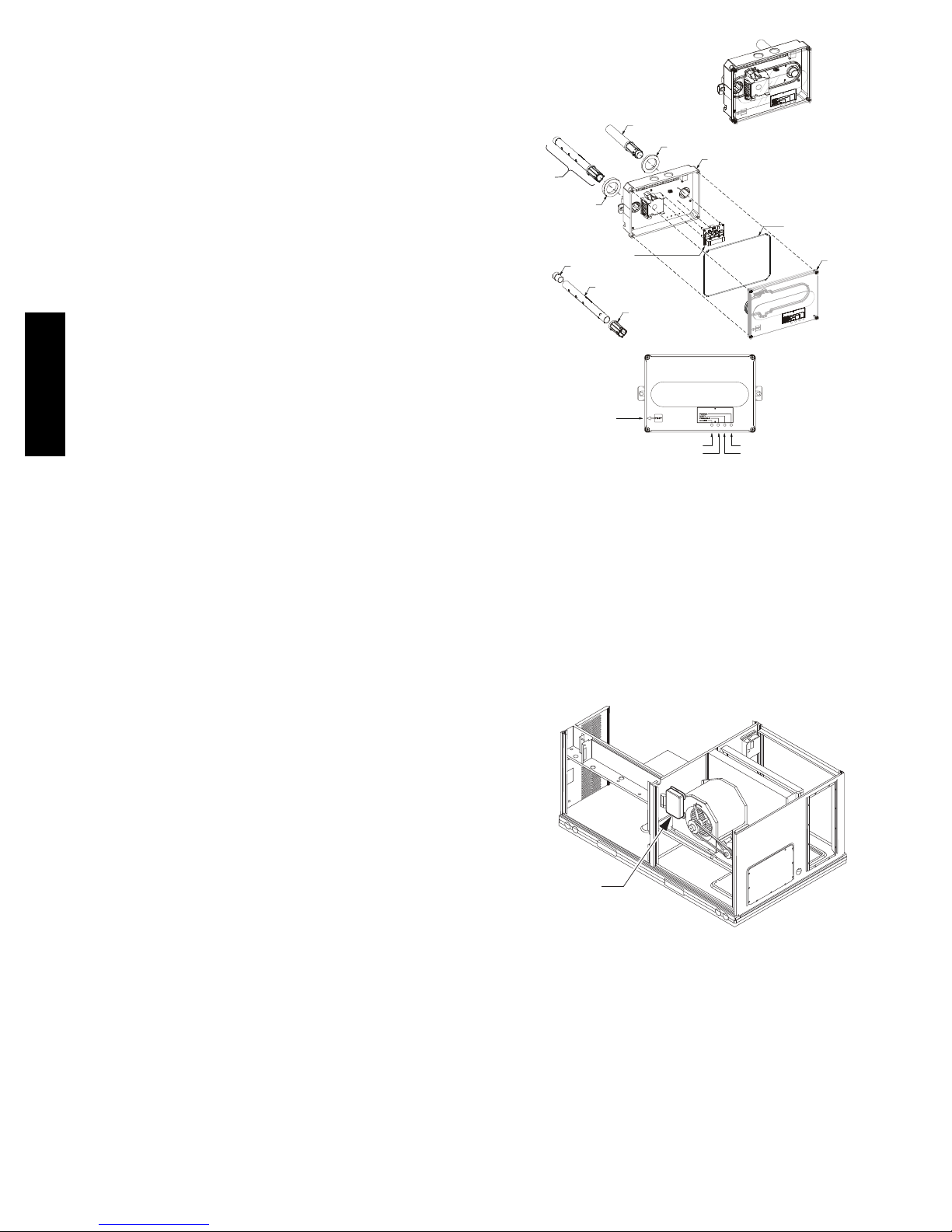
Controller
The controller (see Fig. 31) includes a controller housing,
a printed circuit board, and a clear plastic cover. The
controller can be connected to one or two compatible duct
smoke sensors. The clear plastic cover is secured to the
housing with a single captive screw for easy access to the
wiring terminals. The controller has three LEDs (for
Power, Trouble and Alarm) and a manual test/reset button
(on the cover face).
DUCT SMOKE SENSOR
CONTROLLER
CONDUIT NUTS
(SUPPLIED BY INSTALLER)
CONDUIT SUPPORT PLATE
CONTROLLER HOUSING
AND ELECTRONICS
CONDUIT COUPLINGS
(SUPPLIED BY INSTALLER)
FASTENER (2X)
ALARM
Fig. 31 -- Controller Assembly
TERMINAL BLOCK COVER
COVER GASKET
(ORDERING OPTION)
TROUBLE
POWER
TEST/RESET
SWITCH
CONTROLLER
COVER
C08208
50HC
25
Smoke Detector Sensor
The Smoke Detector Sensor (see Fig. 32) includes a
plastic housing, a printed circuit board, a clear plastic
cover, a sampling tube inlet and an exhaust tube. The
sampling tube (when used) and exhaust tube are attached
during installation. The sampling tube varies in length
depending on the size of the rooftop unit. The clear plastic
cover permits visual inspections without having to
disassemble the sensor. The cover attaches to the sensor
housing using four captive screws and forms an airtight
chamber around the sensing electronics. Each sensor
includes a harness with an RJ45 terminal for connecting to
the controller. Each sensor has four LEDs (for Power,
Trouble, Alarm and Dirty) and a manual te st/reset button
(on the left--side of the housing).
Air is introduced to the duct smoke detector sensor’s
sensing chamber through a sampling tube that extends into
the HVAC duct and is directed back into the ventilation
50HC
system through a (shorter) exhaust tube.
The difference in air pressure between the two tubes pulls
the sampled air t hrough the sensing chamber. When a
sufficient amount of smoke is detected in the sensing
chamber, the sensor signals an alarm state and the
controller automatically takes the appropriate action to
shut down fans and blowe rs, change over air handling
systems, notify the fire alarm control panel, etc.
The sensor uses a process called differential sensing to
prevent gradual environmental changes from triggering
false alarms. A rapid change in environmental conditions,
such as smoke from a fire, causes the sensor to signal an
alarm state but dust and debris accumulated over time
does not.
The difference in air pressure between the two tubes pulls
the sampled air t hrough the sensing chamber. When a
sufficient amount of smoke is detected in the sensing
chamber, the sensor signals an alarm state and the
controller automatically takes the appropriate action to
shut down fans and blowe rs, change over air handling
systems, notify the fire alarm control panel, etc.
SEE DETAIL A
INTAKE
GASKET
(ORDERING OPTION)
PLUG
SAMPLING TUBE
(ORDERED SEPARATELY)
A
DETAIL
MAGNETIC
TEST/RESET
SWITCH
TSD-CO2
EXHAUST TUBE
COUPLING
TROUBLE
EXHAUST GASKET
ALARM
DUCT SMOKE SENSOR
SENSOR HOUSING
AND ELECTRONICS
POWER
DIRTY
COVER GASKET
(ORDERING OPTION)
SENSOR
COVER
C08209
Fig. 32 -- Smoke Detector Sensor
Smoke Detector Locations
Supply Air: The Supply Air Smoke Detector Sensor is
located to the left of the unit’s indoor (supply) fa n. See
Fig. 33. Access is through the fan access panel. There is
no sampling tube used at this location. The sampling tube
inlet extends through the side plate of the fan housing
(into a high pressure area). The controller is located on a
bracket to the right of the return filter, accessed through
the lift--off filter panel.
For installations using two sensors, the duct smoke
detector does not differentiate which sensor signals an
alarm or trouble c ondition.
SUPPLY AIR
SMOKE DETECTOR
C08245
Fig. 33 -- Typical Supply Air Smoke Detector Sensor
Location
26
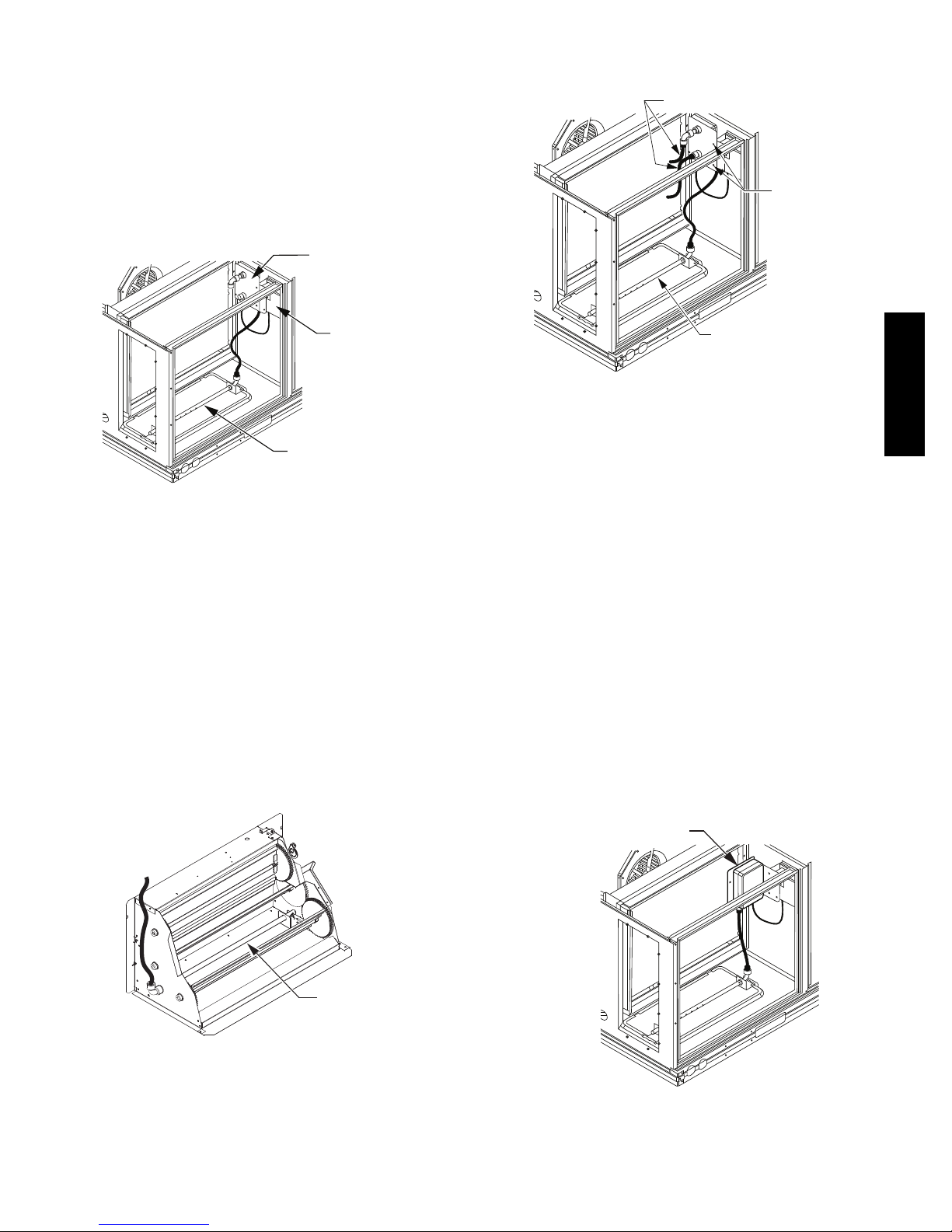
Return Air Smoke Detector Sensor without
Economizer: The sampling tube is located across the
return air opening on the unit basepan. See Fig. 34. The
holes in the sampling tube face downward, into the return
air stream. The sampling tube is connected through tubing
to the return air sensor that is mounted on a bracket high
on the partition between return filter and controller
location. (Thi s sensor is shipped in a flat--mounting
location. Installation requires that this sensor be relocated
to its operating location and the tubing to the sampling
tube be connected. See installation steps below.)
RETURN AIR
DETECTOR MODULE
(Shipping position
shown)*
Completing Installation of Return Air Smoke
Detector:
FLEXIBLE EXHAUST TUBES
SCREWS
CONTROLLER
MODULE
RETURN AIR DETECTOR
SAMPLING TUBE
*RA detector must be moved from shipping
position to operating position by installer
C07307
Fig. 34 -- Typical Return Air Smoke Detector Location
Return Air Smoke Detector Sensor with Economizer:
The sampling tube is inserted through the side plates of
the economizer housing, placing it across the return air
opening on the unit basepan. See Fig. 35. The holes in the
sampling tube face downward, into the return air stream.
The sampling tube is connected using tubing to the return
air sensor mounted on a bracket high on the partition
between return filter and controller location. The sensor is
shipped in a flat--mounting location. Installation requi res
the sensor be relocated to its operating location and the
tubing to the sampling tube be connected. See installation
steps below.
SAMPLE TUBE
C12049
Fig. 36 -- Return Air Smoke Detector Module
Shipping Position
Use the following steps to complete the installation of the
Return Air Smoke Detector.
1. Unscrew the two screws holding the Return Air
Sensor Detector plate. See Fig. 36. Save the screws.
2. Remove the Return Air Smoke Sensor Module and its
detector plate.
3. Rotate the detector plate so the sensor is facing outwards and the sampling tube connection is on the bottom. See Fig. 37.
4. Screw the sensor and detector plate into its operating
position using screws from Step 1. Ensure the
sampling tube connection is on the bottom and the exhaust tube is on the top. See Fig. 37.
5. Connect the flexible tube on the sampling inlet to the
sampling tube on the basepan.
6. For units with an economizer, the sampling tube is
integrated into the economizer housing but
connecting the flexible tubing to the sampling tube is
the same.
RETURN AIR SENSOR
(Operating Position Shown)
50HC
Fig. 35 -- Return Air Sampling Tube Location
(View is reoriented to show opposite side for clarity.)
RETURN AIR
SAMPLING TUBE
C08129
C12050
Fig. 37 -- Return Air Sensor Operating Position
27
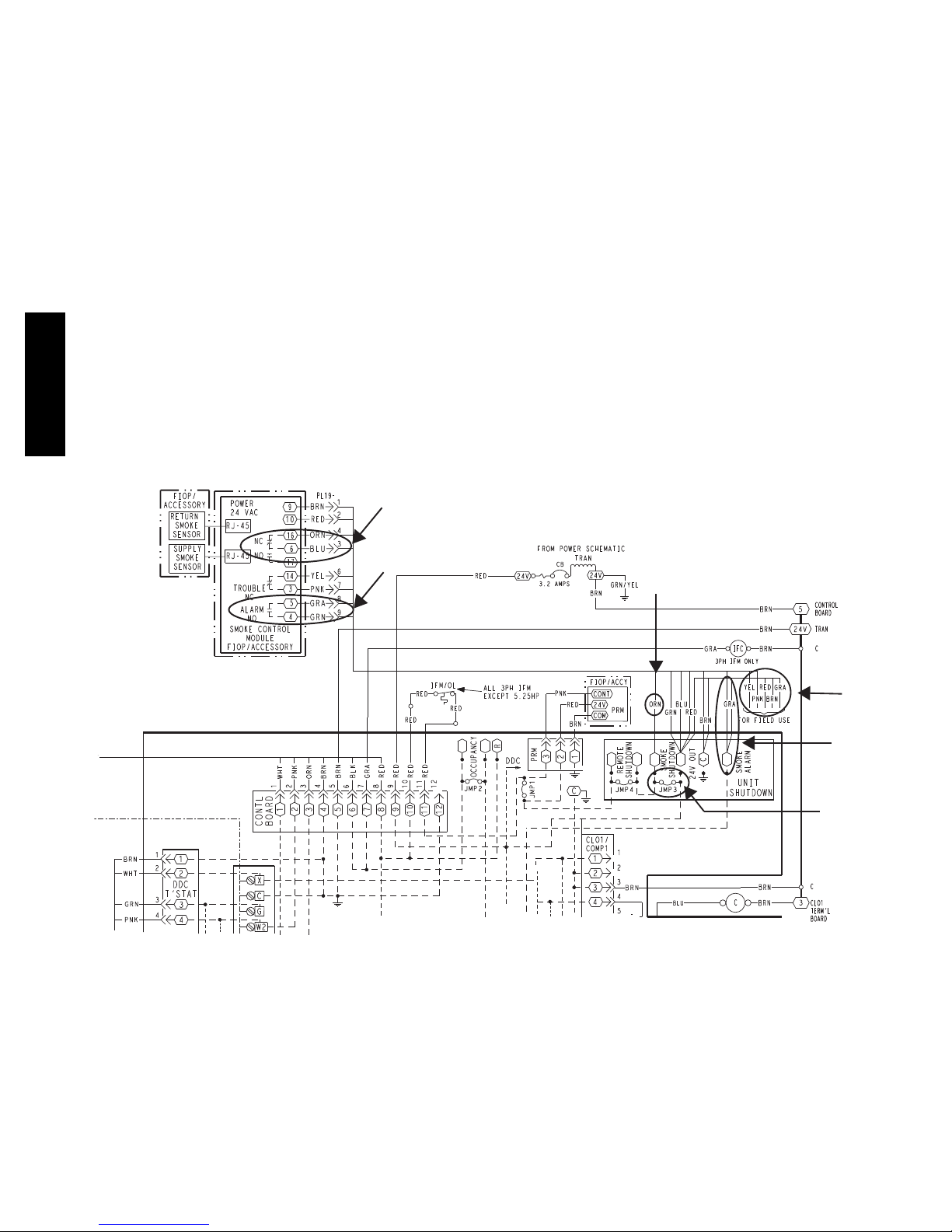
FIOP Smoke Detector Wiring and Response
All units: FIOP smoke detector is configured to
automatically shut down all unit operations when a smoke
condition is detected. See Fig. 38, Smoke Detector
Wiring.
Highlight A: JMP 3 is factory--cut, transferring unit
control to smoke detector.
Highlight B: Smoke detector NC contact set will open on
smoke al arm condition, de--energizing the ORN
conductor.
Highlight C: 24V power signal using the ORN lead is
removed at the Smoke Detector input on LCTB; all unit
operations cease immediately.
PremierLink and RTU--OPEN Controls: Unit
operating functions (fan, cooling and heating) are
terminated as described above. In addition:
50HC
Highlight D: On smoke alarm condition, the smoke
detector NO Alarm contact will close, supplying 24--v
power to GRA conductor.
Highlight E: GRA lead at Smoke Alarm input on LCTB
provides 24--v signal to FIOP DDC control .
Premier--Link: This signal is conveyed to PremierLink
FIOP’s TB1 at terminal TB1--6 (BLU lead). This signal
initiates the FSD sequence by the PremierLink control.
FSD status is reported to connected CCN network.
RTU--OPEN: The 24--v signal is conveyed to
RTU--OPEN -- J1--10 input terminal. This signal initiates
the FSD sequence by the RTU--OPEN control. FSD sta tus
is reported to connected BAS network.
Using Remote Logic: Five conductors are provided for
field use (see Highlight F) for additional annunciation
functions.
Additional Application Data: Refer to Catalog No.
HKRNKA--1XA for discussions on additional control
features of these smoke detectors including multiple unit
coordination. See Fig. 38.
B
D
Fig. 38 -- Typical Smoke Detector System Wiring
C
F
E
A
C08246
28

SENSOR AND CONTROLLER
TESTS
Sensor Alarm Test
The sensor alarm test checks a sensor’s ability to signal an
alarm state. This test requires that you use a field provided
SD--MAG test magnet.
3. Reset the sensor by pressing the test/reset switch for
two seconds.
4. Verify that the controller’s Alarm LED turns off.
Dirty Controller Test
The dirty controller test checks the controller’s ability to
initiate a dirty sensor test and indicate its results.
NOTICE
OPERATIONAL TEST ALERT
Failure to follow this ALERT can result in an
unnecessary evacuation of the facility.
This test places the duct detector into the alarm state.
Unless part of the test, disconnect all auxiliary
equipment from the controller before performing the
test. If the duct detector is connected to a fire alarm
system, notify the proper authorities before
performing the test.
Sensor Alarm Test Procedure
1. Hold the test magnet where indicated on the side of
the sensor housing for seven seconds.
2. Verify that the sensor’s Alarm LED turns on.
3. Reset the sensor by holding the test magne t against
the sensor housing for two seconds.
4. Verify that the sensor’s Alarm LED turns off.
Controller Alarm Test
The controller alarm test checks the controller’s ability to
initiate and indicate an alarm state.
NOTICE
OPERATIONAL TEST ALERT
Failure to follow this ALERT can result in an
unnecessary evacuation of the facility.
Pressing the controller’s test/reset switch for longer
than seven seconds will put the duct detector into the
alarm state and activate all automatic alarm responses.
Dirty Controller Test Procedure
1. Press the controller’s test/reset switch for two
seconds.
2. Verify that the controller’s Trouble LED flashes.
Dirty Sensor Test
The dirty sensor test provides an indication of the sensor’s
ability to compensate for gradual environmental changes.
A sensor that can no longer compensate for environmental
changes is considered 100% dirty and requires cleaning or
replacing. You must use a field provided SD--MAG test
magnet to initiate a sensor dirty test. The sensor’s Dirty
LED indicates the results of the dirty test as shown in
Table 7.
NOTICE
50HC
NOTICE
OPERATIONAL TEST ALERT
Failure to follow this ALERT can result in an
unnecessary evacuation of the facility.
This test places the duct detector into the alarm state.
Unless part of the test, disconnect all auxiliary
equipment from the controller before performing the
test. If the duct detector is connected to a fire alarm
system, notify the proper authorities before
performing the test.
Controller Alarm Test Procedure
1. Press the controller’s test/reset switch for seven
seconds.
2. Verify that the controller’s Alarm LED turns on.
OPERATIONAL TEST ALERT
Failure to follow this ALERT can result in an
unnecessary evacuation of the facility.
Holding the test magnet against the sensor housing for
more than seven seconds wil l put the duct detector
into the alarm state and activate all automatic alarm
responses.
Table 7 – Dirty L E D Te st
FLASHES DESCRIPTION
1 0---25% dirty. (Typical of a newly installed detector)
2 25 ---50% dirty
3 51 ---75% dirty
4 76 ---99% dirty
29
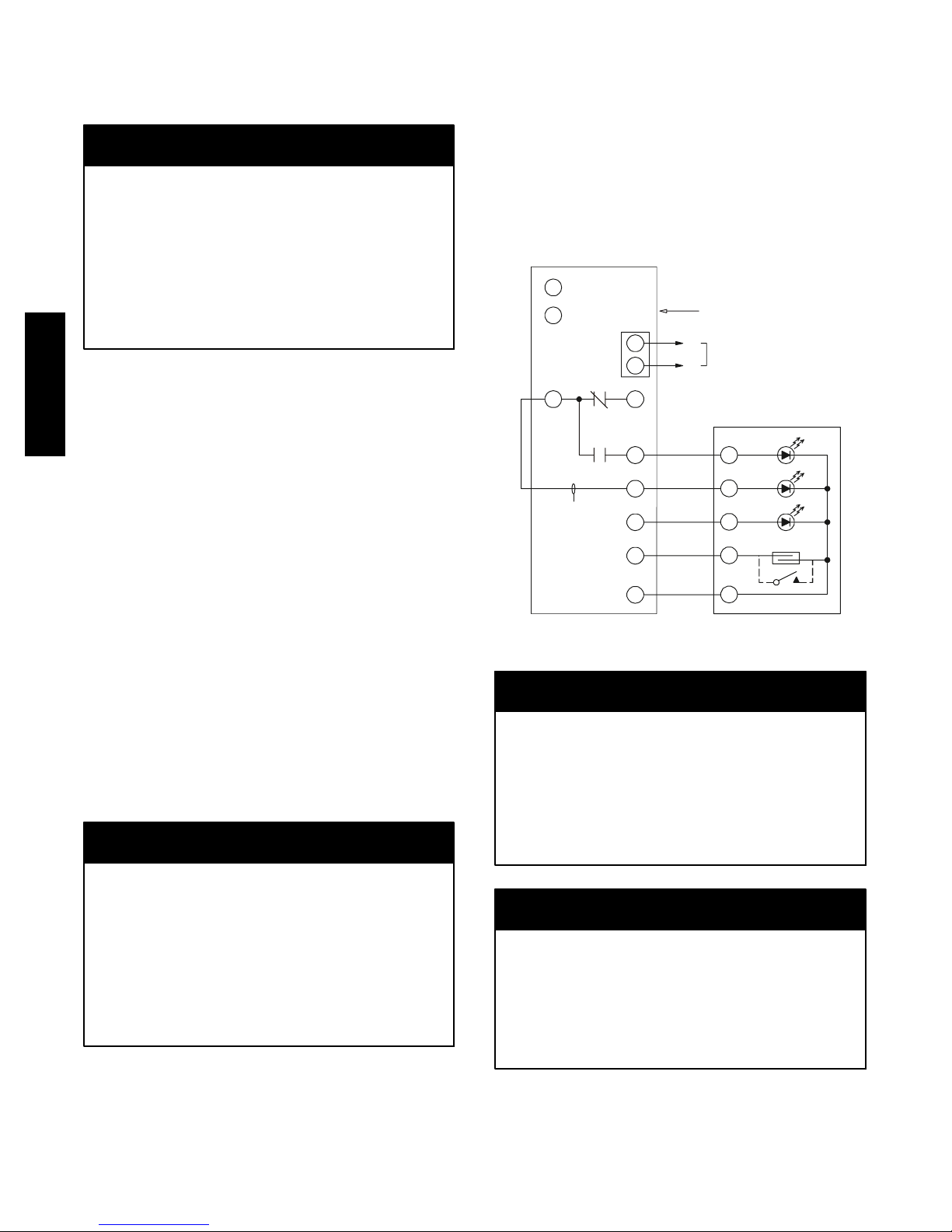
Dirty Sensor Test Procedure
1. Hold the test magnet where indicated on the side of
the sensor housing for two seconds.
2. Verify that the sensor’s Dirty LED flashes.
NOTICE
OPERATIONAL TEST ALERT
Failure to follow this ALERT can result in an
unnecessary evacuation of the facility.
Changing the dirty sensor test operation will put the
detector into the alarm state and activate all automatic
alarm responses. Before changing dirty sensor test
operation, disconnect all auxiliary equipment from the
controller and notify the proper authorities if
connected to a fire alarm system.
Changing the Dirt Sensor Test
50HC
By default, sensor dirty test results are indicated by:
S The sensor’s Dirty LED flashing.
S The controller’s Trouble LED flashing.
S The controller’s supervision relay contacts toggle.
The operation of a sensor’s dirty test can be changed so
that the controller’s supervision relay is not used to
indicate test results. When two detectors are connected to
a controller, sensor dirty test operation on both sensors
must be configured to operate in the same manner.
To Configure the Dirty Sensor Test Operation
1. Hold the test magnet where indicated on the side of
the sensor housing until the sensor’s Alarm LED turns
on and its Dirty LE D flashes twice (approximately 60
seconds).
2. Reset the sensor by removing the test magnet then
holding it against the sensor housing again until the
sensor’s Alarm LED turns off (approximately 2
seconds).
Remote Station Test
The remote station alarm test checks a test/reset station’s
ability to initiate and indicate an alarm state.
NOTICE
3. Reset the sensor by turning the key switch to the
RESET/TEST position for two seconds.
4. Verify that the test/reset station’s Alarm LED turns
off.
Remote Test/Reset Station Dirty Sensor Test
The test/reset station dirty sensor test checks the test/reset
station’s ability to initiate a sensor dirty test and indicate
the results. It must be wired to the controller as shown in
Fig. 39 and configured to operate the controller’s
supervision relay. For more information, see “Changing
sensor dirty test operation.”
12
1
3
S
upe
contacts [3]
W
ire must be
added by installer
rv
ision relay
TB3
1
2
14
1
3
19
15
2
20
Smoke Detector Controller
−
equipment
+
18 Vdc ( )
+
18 Vdc ( )
−
Auxiliary
5
4
1
3
2
SD-TRK4
Trouble
P
ower
Alarm
Reset/Test
C08247
Fig. 39 -- Remote Test/Reset Station Connections
NOTICE
OPERATIONAL TEST ALERT
Failure to follow this ALERT can result in an
unnecessary evacuation of the facility.
If the test/reset station’s key switch is left in the
RESET/TEST position for longer than seven seconds,
the detector will automatically go into the alarm state
and activate all automatic alarm responses.
OPERATIONAL TEST ALERT
Failure to follow this ALERT can result in an
unnecessary evacuation of the facility.
This test places the duct detector into the alarm state.
Unless part of the test, disconnect all auxiliary
equipment from the controller before performing the
test. If the duct detector is connected to a fire alarm
system, notify the proper authorities before
performing the test.
SD--TRK4 Remote Alarm Test Procedure
1. Turn the key switch to the RESET/TEST position for
seven seconds.
2. Verify that the test/reset station’s Alarm LED turns
on.
NOTICE
OPERATIONAL TEST ALERT
Failure to follow this ALERT can result in an
unnecessary evacuation of the facility.
Holding the test magnet to the target area for longer
than seven seconds will put the detector into the alarm
state and activate all automatic alarm responses.
Dirty Sensor Test Using an SD--TRK4
1. Turn the key switch to the RESET/TEST position for
two seconds.
30
 Loading...