

Page 1
40VMF009A-048A
4-Way Cassette Indoor Unit for
Variable Refrigerant Flow (VRF) Systems
Installation and Maintenance Instructions
CONTENTS
Page
SAFETY CONSIDERATIONS . . . . . . . . . . . . . . . . . .1,2
GENERAL . . . . . . . . . . . . . . . . . . . . . . . . . . . . . . . . . 2-5
INSTALLATION . . . . . . . . . . . . . . . . . . . . . . . . . . . . 6-15
Step 1 — Unpack and Inspect Units . . . . . . . . . . . . 6
• PROTECTING UNITS FROM DAMAGE
• PREPARING JOBSITE FOR UNIT INSTALLATION
• IDENTIFYING AND PREPARING UNITS
Step 2 — Position the Unit . . . . . . . . . . . . . . . . . . . . 6
Step 3 — Mount the Unit . . . . . . . . . . . . . . . . . . . . . . 7
• INSTALLING HANGER BOLTS
• MOUNTING UNIT
• INSTALLING PANEL
Step 4 — Connect Piping . . . . . . . . . . . . . . . . . . . . . . 8
• CONDENSATE PIPING
• REFRIGERANT PIPING
Step 5 — Complete Electrical Connections. . . . . . 9
Step 6 — Position and Connect Controller . . . . . 11
ACB Interface . . . . . . . . . . . . . . . . . . . . . . . . . . . . . 15
START-UP . . . . . . . . . . . . . . . . . . . . . . . . . . . . . . . . . . 15
Pre-Start Check . . . . . . . . . . . . . . . . . . . . . . . . . . . . . 15
System Operation Check . . . . . . . . . . . . . . . . . . . . 15
MAINTENANCE. . . . . . . . . . . . . . . . . . . . . . . . . . . . . . 15
INDOOR UNIT ADDRESSING. . . . . . . . . . . . . . 15-17
Wireless Remote Controller (40VM900001) . . . . . 15
Non-Programmable Controller (40VM900002). . . 16
Programmable Controller (40VM900003). . . . . . . 16
TROUBLESHOOTING . . . . . . . . . . . . . . . . . . . . . 17-19
Replacement Parts . . . . . . . . . . . . . . . . . . . . . . . . . . 19
APPENDIX A — DIP SWITCH SETTINGS . . . . . . . . 20
SAFETY CONSIDERATIONS
Improper installation, adjustment, alteration, service,
maintenance, or use can cause explosion, fire, electrical shock,
or other conditions which may cause death, personal injury or
property damage. The qualified installer or agency must use
factory-authorized kits or accessories when modifying this
product.
Follow all safety codes. Wear safety glasses, protective
clothing, and work gloves. Use quenching cloth for brazing
operations. Have fire extinguisher available. Read these
instructions thoroughly and follow all warnings or cautions
included in literature and attached to the unit. Consult local
building codes and the current editions of the National
Electrical Code (NEC) ANSI/NFPA (American National
Standards Institute/National Fire Protection Association) 70. In
Canada, refer to the current editions of the Canadian Electrical
Code CSA (Canadian Standards Association) C22.1.
Understand the signal words — DANGER, WARNING,
and CAUTION. DANGER identifies the most serious hazards
which will result in severe personal injury or death.
WARNING signifies hazards that could result in personal
injury or death. CAUTION is used to identify unsafe practices,
which would result in minor personal injury or product and
property damage.
Recognize safety information. This is the safety-alert
symbol ( ). When this symbol is displayed on the unit and in
instructions or manuals, be alert to the potential for personal
injury. Installing, starting up, and servicing equipment can be
hazardous due to system pressure, electrical components, and
equipment location.
WARNING
Electrical shock can cause personal injury and death. Shut
off all power to this equipment during installation. There
may be more than one disconnect switch. Tag all
disconnect locations to alert others not to restore power
until work is completed.
WARNING
When installing the equipment in a small space, provide
adequate measures to avoid refrigerant concentration
exceeding safety limits due to refrigerant leak. In case of
refrigerant leak during installation, ventilate the space
immediately. Failure to follow this procedure may lead to
personal injury.
WARNING
DO NOT USE TORCH to remove any component. System
contains oil and refrigerant under pressure.
To remove a component, wear protective gloves and
goggles and proceed as follows:
a. Shut off electrical power to unit.
b. Recover refrigerant to relieve all pressure from
system using both high-pressure and low pressure
ports.
c. Traces of vapor should be displaced with nitrogen
and the work area should be well ventilated.
Refrigerant in contact with an open flame produces
toxic gases.
d. Cut component connection tubing with tubing cutter
and remove component from unit. Use a pan to catch
any oil that may come out of the lines and as a gage
for how much oil to add to the system.
e. Carefully unsweat remaining tubing stubs when
necessary. Oil can ignite when exposed to torch
flame.
Failure to follow these procedures may result in personal
injury or death.
Manufacturer reserves the right to discontinue, or change at any time, specifications or designs without notice and without incurring obligations.
Catalog No. 18-40VMF002-01 Printed in U.S.A. Form 40VMF-2SI Pg 1 1-18 Replaces: 40VMF-1SI
Page 2
CAUTION
LEGEND
VRF — Variable Refrigerant Flow
40 VM F
009
--
3
Equipment Type
40 —
Indoor Unit
Product Type
VM — VRF
Blank
Voltage (V-Ph-Hz)
3 — 208/2 3 0-1-60
Model Type
F — 4-Way Cassette
Capacity (Btuh)
009
— 9,000
012
— 12,000
015
— 15,000
024
— 24,000
018
— 19,100
030
— 30,000
036
— 36,000
A40-1914
048
— 48,000
LEGEND
VRF — Variable Refrigerant Flow
A
Design Revision
DO NOT re-use compressor oil or any oil that has been
exposed to the atmosphere. Dispose of oil per local codes
and regulations. DO NOT leave refrigerant system open to
air any longer than the actual time required to service the
equipment. Seal circuits being serviced and charge with
dry nitrogen to prevent oil contamination when timely
repairs cannot be completed. Failure to follow these
procedures may result in damage to equipment. For
information about replacement oil type and viscosity, see
the Installation, Start-Up, and Service Instructions for the
38VMAH and 38VMAR outdoor units.
GENERAL
The 40VMF 4-way ceiling cassette effectively makes each
area served an independently controlled temperature zone.
Through thermostatic control of operations, conditions can be
varied to suit diverse requirements and activities.
The equipment is initially protected under the
manufacturer’s standard warranty; however, the warranty is
provided under the condition that the steps outlined in this
manual for initial inspection, proper installation, regular
periodic maintenance, and everyday operation of the unit be
followed in detail. This manual should be fully reviewed in
advance before initial installation, start-up and any
maintenance. Contact your local sales representative or the
factory with any questions BEFORE proceeding.
Table 1 lists physical data for each unit size. See Fig. 1 for
model number nomenclature. Figure 1 shows unit dimensions.
Table shows components that may or may not be used for a
particular installation.
Fig. 1 — Model Number Nomenclature
2
Page 3
Table 1 — 40VMF Physical Data
UNIT 40VMF 009 012 015 018 024 030 036 048
POWER SUPPLY (V-Ph-Hz) 208/230-1-60
COOLING CAPACITY (Btuh) 9,000 12,000 15,000 19,100 24,000 30,000 36,000 48,000
HEATING CAPACITY (Btuh) 10,900 13,600 17,000 21,500 27,000 34,000 42,000 54,000
ELECTRICAL CHARACHTERISTICS
Typ e DC
Input (W) 40
INDOOR COIL
Number of Rows 23
Fin Spacing (fins/in.) 17
Fin Type Hydrophilic Aluminum
Tube Diameter, OD (in.) 0.276
Tube Type Inner Groove
Number of Circuits 412
INDOOR AIRFLOW (cfm)
Low 330
Medium 390
High 460
INDOOR NOISE LEVEL (dBA)
Low 32.1
Medium 34.0
High 36.7
UNIT
Unit Dimensions, W x H x D (in.) 33
Packing Dimensions, W x H x D (in.) 37 5/8 x 10 5/8 x 37 5/
Panel / Grille Dimensions, W x H x D (in.) 37 3/8 x 1 3/4 x 37 3/
Panel / Grille Dimensions (in.) 40 7/8 x 3 5/8 x 40 7/
Unit Net/Gross Weight (lb) 54/71 69/86
Panel/Grille Net/Gross Weight (lb) 13.2/20
REFRIGERATION TYPE R-410A
EXPANSION DEVICE EEV
DESIGN PRESSURE, High/Low (psig) 580/320
AIR FILTER —
REFRIGERANT PIPING (in.)
Liquid Side, OD (Flare)
Suction Side, OD (Flare)
CONNECTING WIRING
Power Wiring Sized per NEC and local codes based on nameplate electrical data
Signal Wiring 2-core shielded twisted pair cable 20 AWG-16 AWG
CONDENSATE DRAIN PIPE DIAMETER, OD
(in.)
LEGEND
AWG — American Wire Gage
EEV — Electronic Expansion Valve
54
390
460
560
33.0
37.3
41.4
1
/8 x 9 x 33 1/
1
/
4
1
/
2
67 153.5 85.4 131.7 182.7 202.3
460 610 610 680 800 950
560 700 700 800 950 1100
680 1000 800 950 1100 1200
37.0 40.2 40.2 42.1 47.3 50.5
41.5 43.1 42.5 45.1 50.4 54.0
45.6 52.5 44.7 49.5 53.9 55.4
8
8
1
33 1/8 x 11 3/4 x 33 1/
37 5/8 x 13 x 37 5/
8
8
1
/
4
8
8
3
/
8
5
/
8
3
Page 4
Table 2 — Components Shipped With Unit
NAME SHAPE QUANTITY FUNCTION
Nut 8 To connect the construction cover board to the fan motor
Washer 8 To connect the construction cover board to the fan motor
Construction cover board 1 Used to cover the fan motor
Bolt 4 To connect the construction cover board to the fan motor
Insulation 2 For covering the coil stub outs
Insulation 1 For covering the condensate drain
Clamp 1 For connecting the drain
Tie rope 5 For insulation
Condensate connection 1 For connecting drain
PQE connection wire 2 To connect outdoor unit, indoor unit, and sub MDC
Copper nut 1 Connect piping
Flexible conduit and connectors 1 Routing power lines
Connecting wire 1 For connecting occupancy sensor
Copper pipe for gas side 1 For connecting the refrigerant pipe
Copper pipe for liquid side 1 For connecting the refrigerant pipe
LEGEND
MDC — Multiport Distribution Controller
4
Page 5
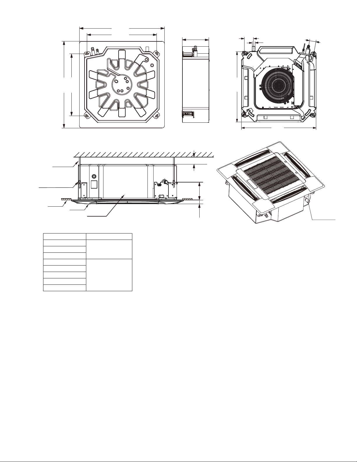
Fig. 1 — 40VMF009-048 Dimensions
NOTE: All dimensions shown in inches.
40VMF UNIT SIZE DIMENSION A
009
9012
015
018
11
3
/
4
024
030
036
048
´
´-1
´
Install hanger
Panel
Ceiling
Main body
Hexagon nut
(For adjust to balance)
í
í
í
í
A
Drainage pipe
2í
í
í
í
DRAIN
CONNECTION
í
5
Page 6
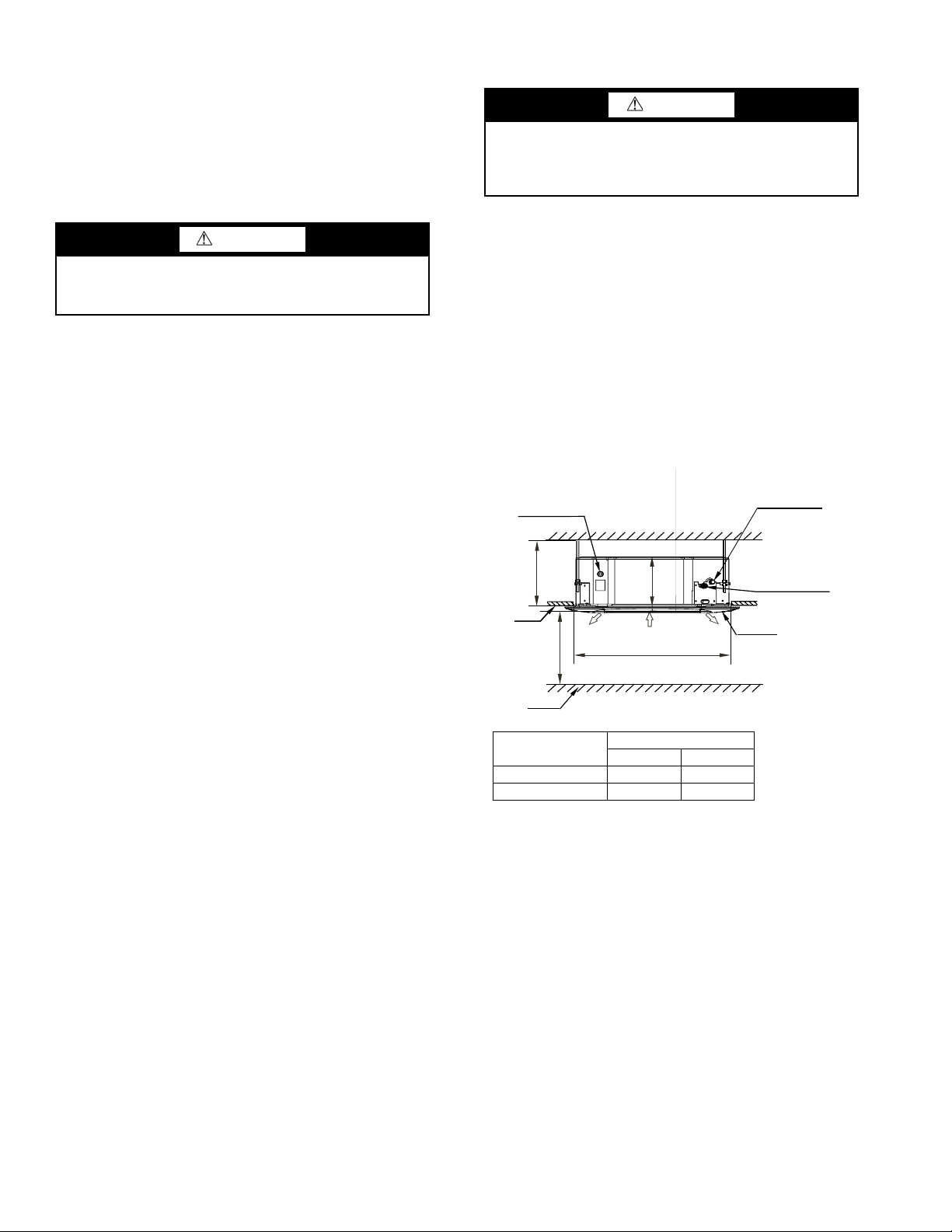
Step 1 — Unpack and Inspect Units —
Fig. 2 — False Ceiling Installation
40VMF UNIT SIZE
DIMENSION (in.)
AH
009-015 9 ³ 10
1
/
4
018-048 11 3/
4
³ 13
A
H
>8-1/4 ft.
Connect to the outlet
of
drainage pipe
Connection port of
(Gas side)
refrigerant pipe
(Liquid side)
Connection port
of refrigerant pipe
Floor
Ceiling
Panel
Air outlet Air inlet
2-7/8 ft. (Ceiling hole)
Air outlet
packaged for shipment to avoid damage during normal transit
and handling. It is the receiving party’s responsibility to inspect
the equipment upon arrival. Any obvious damage to the carton
and/or its contents should be reported on the bill of lading and a
claim should be filed with the transportation company and the
factory. Unit should always be stored in a dry place, and in the
proper orientation as marked on the carton.
To avoid equipment damage, do not lift unit by the drain
pipe or refrigerant piping. Unit should be lifted using the
mounting brackets.
After determining the condition of the carton exterior,
carefully remove each unit from the carton and inspect for
hidden damage. Check to make sure that items such as
thermostats, controller etc. are accounted for whether packaged
separately or shipped at a later date. Any hidden damage
should be recorded, a claim should be filed with the
transportation company, and the factory should be notified. In
the event a claim for shipping damage is filed, the unit,
shipping carton, and all packing must be retained for physical
inspection by the transportation company. All units should be
stored in the factory shipping carton with internal packaging in
place until installation.
PROTECTING UNITS FROM DAMAGE — Do not apply
force or pressure to the coil, piping, or drain stub-outs during
handling. All units should be handled by the chassis or as close
as possible to the unit mounting point locations.
The unit must always be properly supported. Temporary
supports used during installation or service must be adequate to
hold the unit securely. To maintain warranty, protect units
against hostile environments (such as rain, snow or extreme
temperature), theft, vandalism, and debris on jobsite.
Equipment covered in this manual is not suitable for outdoor
installations. Do not allow foreign material to fall into drain
pan. Prevent dust and debris from being deposited on motor,
fan wheels and coils. Failure to do so may have serious adverse
effects on unit operation and in the case of motor and blower
assembly, may result in immediate or premature failure. Failure
of any unit caused by deposits of foreign material on the motor
or blower wheels will not be covered by the manufacturer’s
warranty. Some units and/or job conditions may require some
form of temporary covering during construction.
PREPARING JOBSITE FOR UNIT INSTALLATION —
To save time and to reduce the possibility of costly errors, set
up a complete sample installation in a typical room at jobsite.
Check all critical dimensions such as pipe, wire, and duct
connections requirements. Refer to job drawings and product
dimension drawings as required. Instruct all trades in their
parts of the installation. Units must be installed in compliance
with all applicable local code requirements.
IDENTIFYING AND PREPARING UNITS — Be sure
power requirements match available power source. Refer to
unit nameplate and wiring diagram. In addition:
• Check all tags on unit to determine if shipping screws are
to be removed. Remove screws as directed.
• Rotate the fan wheel by hand to ensure that the fan is
unrestricted and can rotate freely. Check for shipping
damage and fan obstructions. Adjust blower motor as
required.
INSTALLATION
CAUTION
Units are
Step 2 — Position the Unit
DANGER
Units must not be installed where they may be exposed to
potentially explosive or flammable atmosphere. If this
instruction is not followed exactly, a fire or explosion may
result, causing property damage, injury, or loss of life.
Install the unit in a location that meets the following
requirements:
• Allow adequate space for installation, service clearance,
piping and electrical connections, and necessary
ductwork. For specific unit dimensions, refer to Table 1
and Fig. 1. Allow clearance according to local and
national codes.
• Confirm that the ceiling is able to support the weight of
the unit. See Table 1 for nominal weight.
• There should be enough room within the false ceiling for
installation and maintenance. See Fig. 2 below.
• The false ceiling should be horizontal and leveled.
• Install the unit in a location within the room that allows
uniform air flow in all directions.
Select the unit position with the following points in mind:
• The unit should be installed in a position that is suitable
to support the total weight of the unit, refrigerant piping
and condensate.
• Proper access should be provided for maintenance for
refrigerant piping, EEV (electronic expansion valve),
electrical box, and condensate pump. A 2-ft clearance is
recommended all around the unit.
• The unit should be at least 3
obstruction. See Fig. 3 below.
6
1
/4 ft from a wall or similar
Page 7

• Do not position where the discharge air could blow
Fig. 3 — Distance from Wall or Obstruction
40 in. MIN.
40 in. MIN.
40 in. MIN.
40 in. MIN.
a40-1720
Unit body
Install the paper board
Central hole
Screw M6×12
Fig. 4 — Paper Board Mounting Hole Locations
Fig. 5 — Example of Buffer Locations
Buffer
Fig. 6 — Mounting Hole Locations
í
í
í
í
directly on the thermostat.
• Recommended distance between 2 units is 10 ft to avoid
conflicting airflow and recirculation.
• The unit should not be positioned directly above any
obstruction.
• The unit must be installed square and level.
• The condensate drain should have sufficient downward
slope (1 in. per 100 in.) in any horizontal run between
unit and drain. Maximum condensate lift is 29
1
/2 inches.
See Fig. 5 for an example of some buffer locations.
The actual quantity
shall prevail
Step 3 — Mount the Unit
INSTALLING HANGER BOLTS — Install the hanger bolts
at the locations shown in Fig. 6. Use
For unit weight, see Table 3.
3
/8-in. all-threaded rod.
IMPORTANT: Be sure that the ceiling grid is supported
separately from the unit. The ceiling grid must not be
supported by an part of the unit or any associated
wiring or piping work.
In case of new construction, once the unit is installed, please
cover the fan motor opening using the construction cover board
to avoid any dust and debris from settling inside the unit. Use
the M6 bolt, washer and nut as shown in Fig. 4 below.
Remove all buffers between the fan and the flared mouth
before installing the indoor unit. Failure to do so will cause
CAUTION
damage to the fan motor.
CAUTION
To avoid equipment damage ensure the unit is placed
horizontally.
Table 3 — Unit Weight
40VMF UNIT WEIGHT (lb)*
009 71.0
012 71.0
015 71.0
018 86.0
024 86.0
030 86.0
036 86.0
048 86.0
*Includes grille weight.
MOUNTING UNIT — The unit can now be lifted on to the
hanging rods for mounting.
1. Use rods and fasteners to suspend the unit at the factoryprovided mounting holes.
2. Adjust the height of the unit until the bottom (without
grille) is level with the false ceiling.
3. Secure the unit in position with locknuts and washers on
both sides of the unit bracket. Ensure that the threaded
rod does not protrude more than 2 in. below the mounting
brackets as shown in Fig. 7.
7
Page 8

INSTALLING PANEL
Fig. 7 — Threaded Rod
a40-1722
Fig. 8 — Removing Grille from Panel
GRILLE
LATCHE
S
CORD
45°
Fig. 9 — Mounting Panel
Louver motor
Louver
motor
Drainage
pipe joint
Hook
Panel hook
Piping joint
Hook bolt
Phillips
screwdriver
Fig. 10 — Condensate Piping
MIN. GRADIENT
2
5
8
TO 3
14
ft
INSULATION
INDOOR
UNIT
FLEXIBLE DRAIN
CONDENSATE HOSE CLAMP
CONNECTOR
PVC DRAIN
PIPE
Fig. 11 — Condensate Drain Connection
NOTE: Panel is ordered separately.
1. Remove the grille from the panel by sliding the grille
latches toward the center of the panel.
2. Lift the grille up at a 45-degree angle and pull to detach it
from the panel.
3. Unscrew the bolts on the 4 corners of the cover panel.
Remove the cover by loosening the cord. See Fig. 8.
5. When the panel is secure, insert the grille at a 45-degree
angle and latch it in place.
Step 4 — Connect Piping
CONDENSATE PIPING — The unit is supplied with a 1 1/4inch OD drain connection to connect copper or plastic drain
piping. When installing condensate piping, follow these
recommendations:
• Maximum pump lift is 29
• The highest point in the condensate piping should be as
close to the unit as possible. See Fig. 10-12 below.
1
/2 inches.
4. Secure the panel (without the grille) onto the unit, using
M5 x 16 screws and washers. Before tightening the
screws, be sure the panel is flush with the false ceiling.
See Fig. 9.
8
Page 9

• Condensate piping should slope downward in the
Fig. 12 — Using a Main Drain to Serve Multiple Indoor Units with Internal Condensate Pumps
2“~4”
2“~4”
2“~4”
Max. 3-3/4 ft.
7-7/8”
7-7/8”
7-7/8”
Connection assembly of water outlet Main drainage pipe
Gradient: 1/50~1/100
direction of condensate flow, with a minimum gradient
of 1 in. per 100 inches.
• When multiple units are connected to a common
condensate drain, ensure that the drain is large enough to
accommodate the volume of condensate from all units. It
is also recommended to have an air vent in the
condensate piping to prevent air lock.
• Condensate piping must not be installed where it may be
exposed to freezing temperatures.
REFRIGERANT PIPING
CAUTION
When connecting from an indoor unit to an outdoor unit,
the isolation valve at the outdoor unit should be in the
closed position throughout the refrigerant piping process.
Failure to follow this procedure may result in equipment
damage.
When connecting from an indoor unit to an outdoor unit,
follow these procedures:
• Check maximum height drop and length of refrigerant
piping between the indoor and outdoor units. To ensure
the drop and length are acceptable, refer to the
refrigerant piping allowable limits in the outdoor unit
installation manual.
• The number of bends in the refrigeration piping must be
fewer than 15.
• Refrigerant piping connection between indoor and
outdoor units should be performed once the units are
secured at their respective installation locations.
• The refrigeration piping starts at the indoor unit and ends
at the outdoor unit or Multiport Distribution Controller
(Heat Recovery systems).
• The refrigerant piping should be dry and free of dust and
other impurities.
• The bending angle of the refrigerant pipe should not
exceed 90 degrees and the bending radius should be as
large as possible to prevent any breakage in piping.
• Use proper cutting and flaring tools to avoid leakage.
• Use a torque wrench for flare nuts. Refer to Table 4 for
flare nut torque recommendations.
Table 4 — Flare Nut Torque Recommendations
OUTSIDE DIAMETER (in.) RECOMMENDED TORQUE (ft-lb)
1/4 15
3/8 26
1/2 41
5/8 48
• Before insulating the suction and liquid refrigeration
pipes, perform pressure and leak tests. For details, see
the outdoor unit installation manual. Insulating both
suction and liquid refrigerant pipes is mandatory.
• Vacuuming and charging of the system should be carried
out as described in the outdoor unit installation manual.
Step 5 — Complete Electrical Connections —
Installation of wiring must conform with local building codes,
or in the absence of local codes, with the National Electric
Code ANSI/NFPA (American National Standards Institute/
National Fire Protection Association) 70, current editions.
Units must be electrically grounded in conformance with the
code. In Canada, wiring must comply with CSA (Canadian
Standards Association) C22.1, Electrical Code.
WARNING
Electrical shock can cause personal injury and death.
Disconnect power supply before making wiring
connections. There may be more than one disconnect
switch. Tag all disconnect locations to alert others not to
restore power until work is completed.
WARNING
All units must be wired strictly in accordance with the
wiring diagram furnished with the unit. Any wiring
different from the wiring diagram could result in personal
injury and property damage.
CAUTION
Any original factory wiring that requires replacement must
be replaced with wiring material having a temperature
rating of at least 221 F.
Ensure supply voltage to the unit, as indicated on the serial
plate, is not more than 10% over the rated voltage or 10%
under the rated voltage.
Failure to follow these recommendations may result in
equipment damage.
This equipment in its standard form is designed for an
electrical supply of 208/230-1-60. Any damage to or failure of
units caused by incorrect wiring or voltage is not covered by
warranty.
Electric wiring must be sized to carry the full load amp
draw of the motor, starter, and any other controls that are used
with the unit. See Table 5 for electrical data.
After the pipe work is complete, the electrical supply can be
connected by routing the cable through the appropriate casing
holes or knockouts and connecting the supply and ground
cables to the unit’s power terminal.
9
Page 10

Be sure the power wiring and control wiring do not cross, as
Fig. 13 — 40VMF009-048 Typical Wiring Diagram
LEGEND
NOTE: Field wiring must use copper conductors only.
ACB — Auxiliary Control Board
AUXH — Output For Auxiliary Heat
CS — Condensate Switch
CTON — Output for Cooling Operation
EEV — Electronic Expansion Valve
FAN — Output for Fan Operation
FM — Indoor Fan Motor
GM — Louver Motor
HTON — Output For Heating Operation
MDC — Multiport Distribution Controller
PUMP — Pump Motor
T1 — Indoor Temperature Sensor
T2A — Evaporator Temperature Sensor
T2B — Evaporator Outlet Temperature Sensor
XP1-9 — Plug
XS1-9 — Jack
XT1-2 — Terminal Block
----------- Optional Component or Field Wiring
Main Board
HA
HB
To
wired controller
comm. bus
ENC2
SW8
T2A T1
T2B
XP1-XP3
XS1-XS3
BLUE
WHITE
RED
XS4
XP4
XP6
XS6
XP5
XS5
CN2
POWER IN
Attention:
For the convenience of
terminals can be pulled
wiring, the
communication
out from the main board.
SW1
CS
CN12
CN11
MDC units comm. bus
T
o outdoor/indoor/
BLUE
RED
CN3
CN18
XT1
FM
ALARM
CN24
CN52
CN9
EEV
CN21
CN5
CN8
CN50
15NC15NC
ACB interface
PUMP
GM
GM
Display board
CN15
L1 L2
Y/G
( Current range: 0-1A)
FAN
CTON
HTON
AUXH
( Voltage range: 0-24V AC/DC)
CN54
ON/OFF
SWITCH
XP7
XP8
P
Q
P
Q
CN14
Occupancy
sensor/ON-OFF
(Dry contact)
ENC1
“ +5V GND +12V ”
ONLY USED
FOR TESTING
this might cause disturbance on the controls side. See Fig. 13
for wiring diagram.
NOTE: The indoor unit requires its own power supply. Indoor
units are not powered through outdoor units.
Table 5 — 40VMF Electrical Data
40VMF UNIT SIZE
009 0.73 15
012 0.91 15
015 1.10 15
018 2.00 15
024 1.30 15
030 1.70 15
036 2.30 15
048 2.40 15
LEGEND
MCA — Minimum Circuit Amps
MOPD — Maximum Overcurrent
Protective Device
POWER SUPPLY
MCA MOPD
10
Page 11

Step 6 — Position and Connect Controller —
Fig. 14 — Communication Wire Connection
To outdoor/indoor/MDC units
comm. bus
To wired controller comm. bus
XT2
Fig. 15 — Shearing Outdoor Connector
Fig. 16 — Stripping the Wire
Fig. 17 — Connecting Communication Wire to
Outdoor Unit Communication Terminal
Fig. 18 — Connecting the Communication Wires
Wired controllers should be installed in a position that
maintains good temperature control:
• Position the thermostat approximately 48 in. above floor
level.
• Do not position thermostat where it can be directly
affected by the unit’s discharge airstream.
• Avoid external walls and drafts from windows and doors.
• Avoid positioning near shelves and curtains as these
restrict air movement.
• Avoid heat sources such as direct sunlight, heaters,
dimmer switches, and other electrical devices
• See Fig. 14 for an example of communication wire
connection.
CONTROL WIRING
1. Use copper core PVC insulated sheathed shielded twisted
cord.
2. For IDU (indoor unit) and ODU (outdoor unit)
communication, use ‘P, Q” terminals. Shielded core
should be used for ground.
3. Wiring should be done according to wiring diagram.
4. Communication wire must not form a closed loop.
3. Use a suitable screwdriver to fix the communication wire
on the outdoor unit communication terminal as shown in
Fig. 17 below.
If communication wires are use to connect indoor units,
then find the corresponding port and plug it directly as shown
in Fig. 18.
OPTION/EXTENSIONS OF COMMUNICATION
WIRING — To extend control wiring or make terminal
connections, use the PQE connection wire supplied in the
accessory kit and follow the steps below.
1. Cut the connector on the outdoor unit side as shown in
Fig. 15 below.
If for any reason it is not possible to buy communication
wires from Carrier, connect the indoor unit side of the
communication wires using the connector provided with the
accessories as shown in Fig. 19. See Fig. 20 and 20 for typical
communication wiring of the heat pump and heat recovery
systems.
CAUTION
Failure to follow these procedures may result in personal
injury or damage to equipment.
NEVER CONNECT the main power source to the control
or communication terminal block.
USE AN APPROPRIATE SCREWDRIVER for
tightening the terminal screws. Do not over tighten the
terminal screws.
IMPORTANT: Communication wiring shall be 2 in. or
more apart from power source wiring to avoid electric
noise. (Do not insert control/communication and power
source wire in the same conduit.)
Pay attention to the polarity of the communication
wire.
2. Strip a suitable length of the insulation layer as shown in
Fig. 16 below.
11
Page 12

Connector in accessory kitConnector on indoor unit Communication cable
in field
Fig. 19 — Connecting the Communication Cable to Indoor Unit to Outdoor Unit Using the Supplied Connector
12
Page 13

P Q
X Y
X Y
MDC unit
Centralized controller
outdoor unit
P Q
P Q
P Q
P Q
P Q
P Q
To No.1
indoor
To No.2
indoor
To No.3
indoor
To No.4
indoor
To No.1
indoor
To No.2
indoor
To Sub MDC
To outdoor
Main MDC unit
To outdoor
L1
L2
L3
L3
L3
L3
L4
L4
L5
L6
L7
L8
L9
L10
L11
Indoor unit 1#
HA HB
Indoor unit 2#
HA HB
Indoor unit 3#
HA HB
Indoor unit 4#
HA HB
Indoor unit 5#
HA HB
Indoor unit 6#
HA HB
HA HB
Touch screen
NOTE: 24 v. DC Power
wired controller
(Field Supplied)
wired controller
HA HB
NOTE: Power from IDU
Maximum wiring length:
L1+L2 </= 3937 ft 18 AWG, 2-Core Stranded Shield
L3 </= 3937 ft 18 AWG, 2-Core Stranded Shield
L4 </= 3937 ft 18 AWG, 2-Core Stranded Shield
L5 </= 3937 ft 18 AWG, 2-Core Stranded Shield
L6+L7+L8+L9 </= 820 ft 18 AWG, 2-Core Stranded Shield
L10+L11 </= 820 ft 18 AWG, 2-Core Stranded Shield
LEGEND
MDC
—
Multiport Distribution Controller
IDU
—
Indoor Unit
Fig. 20 — Typical Heat Recovery Communication Wiring Diagram
13
Page 14

Fig. 20 — Typical Heat Pump Communication Wiring Diagram
P Q
X Y
X Y
Centralized controller
outdoor unit
P Q
P Q
P Q
P Q
P Q
P Q
L1
L3
L5
L6
L7
L8
L9
L10
L11
L3
L3
L3
L3
Indoor unit 1#
HA HB
Indoor unit 2#
HA HB
Indoor unit 3#
HA HB
Indoor unit 4#
HA HB
Indoor unit 5#
HA HB
Indoor unit 6#
HA HB
P
Q
Network Resistor
HA HB
Touch screen
NOTE: 24 v. DC Power
wired controller
(Field Supplied)
wired controller
HA HB
NOTE: Power from IDU
Maximum wiring length
L1+L3 </= 3937 ft 18 AWG, 2-Core Stranded Shield
L5 </= 3937 ft 18 AWG, 2-Core Stranded Shield
L6+L7+L8+L9 </= 820 ft 18 AWG, 2-Core Stranded Shield
L10+L11 </= 820 ft 18 AWG, 2-Core Stranded Shield
LEGEND
IDU
—
Indoor Unit
NOTE: Network resistor is shipped with the outdoor unit for field installation on
heat pump systems.
14
Page 15

ACB Interface — The ACB interface is a dry contact
LEGEND
ACB
—
Auxiliary Control Board
AUXH
—
Output For Auxiliary Heat
CTON
—
Output For Cooling Operation
FAN
—
Output For Fan Operation
HTON
—
Output For Heating Operation
MAX AMPS 1A
MAX VOLTAGE 24V
Fig. 21 — ACB Interface
CN51
ACB interface
CN50
FAN
CTON
HTON
AUXH
board, it can output up to four signals controlling devices.
Please refer to Fig. 21 for connecting devices to the ACB
interface board.
Pre-Start Check —
the following pre-start checks:
1. All indoor and outdoor units are properly installed.
2. All piping and insulation is complete.
3. All electrical connections (both power and control) are
properly terminated.
4. All condensate drains are installed correctly.
5. The power supply is of the right voltage and frequency.
6. The units are properly grounded in accordance with
current electrical codes.
7. Suction and liquid line isolation valves are in open
position.
System Operation Check — Once the installation
and pre-start checks are completed, follow these steps:
1. Using remote controller, select cooling or heating mode
to check the operation of the system.
2. While the system is in operation, check the following on
indoor unit:
a. Switches or buttons on the remote controller are easy to
push.
b. Indicator light is showing normal operation and no
error is indicated.
c. Swing mode of air louvers is working (if applicable to
unit).
d. Drain pump operation is normal (if applicable).
e. No abnormal vibration or noise is noticed.
3. While the system is in operation, check the following on
outdoor unit:
a. No abnormal vibration or noise is noticed.
START-UP
Once installation is complete, make
b. Condenser fan is in operation.
c. Indicator light is showing normal operation and no
error is indicated.
NOTE: If the unit is turned off or restarted, there is a time
delay of 3 minutes for the compressor to start from the time the
power is restored.
MAINTENANCE
CAUTION
When servicing or repairing this unit, use only factoryapproved service replacement parts. Refer to the rating
plate on the unit for complete unit model number, serial
number and company address. Any substitution of parts or
controls not approved by the factory will be at the owner’s
risk and may result in equipment damage.
CAUTION
To avoid equipment damage, do not attempt to reuse any
mechanical or electrical controllers that have been wet.
Replace defective controller.
EVERY 3 MONTHS:
• Check the air filter condition. Clean or replace if
necessary.
EVERY 6 MONTHS — Follow 3-month maintenance
schedule. In addition:
• Clean condensate tray with suitable cleaning agent.
• Clean the grille and panel.
EVERY 12 MONTHS — Follow 6-month maintenance
schedule. In addition:
• Be sure all electrical connections are secure.
• Check condensate pump operation.
• Check the heating and cooling action to confirm proper
operation.
INDOOR UNIT ADDRESSING
For proper system operation each indoor unit must have a
unique address set from 0 to 63. When setting an address by
remote controller the outdoor units, indoor units, and MDC
must be powered on. If “FE” is displayed on the LED screen or
display board this unit has no address. After setting all indoor
units’ addresses, turn off the power supply to all indoor units to
clear errors.
Indoor units’ addressing can be distributed automatically in
the heat pump system. When dip switch “S6” on the outdoor
units main PCB board is set to 00 (default set in factory) indoor
unit’s are set for auto-addressing. When powering on for the
first time it takes 6 minutes or more to finish auto-addressing
each indoor unit. The heat recovery system cannot accomplish
this function at this time.
Wireless Remote Controller (40VM900001) —
Indoor unit addressing can be performed using the wireless
remote controller. When using the wireless controller, the user
must maintain a line of sight with the receiver on the indoor
unit. See Fig. 22 for a description of the buttons on the wireless
remote.
15
Page 16

Use a tool to press and hold the LOCK button for at least 10
RESET
TIMERON
TIMEROFF
SWING
AIRDIRECTION
CLOCK
OK
SWING
MODE
FAN
AUTO
COOL
DRY
HEAT
FAN
TEMP
SET
CLOCK
SET
HOUR
FANSPEED
LOCK
C/H
6 – AIR DIRECTION
2 – FAN SPEED SETTING
4 – ADJUST UP
9 – CLOCK SETTING
14 – OK (CONFIRM)
10 – TIMER ON
11 – TIMER OFF
1 – MODE SETTING
3 – ADJUST DOWN
12 – RESET
13 – LOCK
15 – COOL/HEAT
5 – ON/OFF
7 – AIR VERT. SWING
A40-1734
Fig. 22 — Wireless Remote Controller
(40VM900001)
MODE
FAN TEMP. DOWN
OK
TEMP. UP ON/OFF
TIMER
ROOM TEMP.
SWING
#
Fig. 23 — Non-Programmable Controller
(40VM900002) IDU Addressing Menu
#
MODE
FAN TEMP. DOWN
OK
ON/OFFTEMP. UP
TIMER
ROOM TEMP.
SWING
Fig. 24 — Non-Programmable Controller
(40VM900002) Setting IDU Address
Fig. 25 — Programmable Controller
(40VM900003) IDU Addressing Menu
MODE
FAN
MENU
TEMP. DOWN
TEMP. UP
OK
BACK
ON/OFF
seconds, then press to activate. Click or to select an
address and press to send the setting.
To display an indoor unit address, use a tool to press and
hold the LOCK button for at least 10 seconds, and press to
query the addresses.
Non-Programmable Controller (40VM900002)
When setting an address, connect only one wired controller to
an indoor unit.
Press ROOM TEMP and SWING simultaneously for 3
seconds. If there is no address for this indoor unit, the display
shows FE# 00 (see Fig. 23). Otherwise, the display shows the
current address of the indoor unit.
Click TEMP. UP or TEMP. DOWN to change 00 to the
desired address as shown in Fig. 24. Then press OK to confirm
and exit the setting interface.
Programmable Controller (40VM900003) —
When setting an address, connect only one wired controller to
an indoor unit.
1. Press FA N and BACK simultaneously for 5 seconds to
access parameter settings as shown in Fig. 25.
2. Press TEMP. UP or TEMP. DOWN to move the cursor
and choose IDU ADDRESSING, then MENU/OK to
access this setting.
16
Page 17

3. Press TEMP. UP or TEMP. DOWN to choose the
Fig. 26 — Programmable Controller
(40VM900003) Setting IDU Address
MODE
FAN
MENU
TEMP. DOWN
OK
TEMP. UP
BACK
ON/OFF
Fig. 27 — LED Display Panel
A40-1716
OPERATION TIMER DEF./FAN ALARM
a40-1842
address you want to set, see Fig. 26. Press MENU/OK to
send this address to the IDU.
4. Press BACK twice or wait 30 sec. to automatically exit
the parameter settings menu.
TROUBLESHOOTING
Figure 27 shows the LED display panel on the indoor unit.
See Table 6 for a summary of display indicators. Table 7 lists
problems, possible causes, and possible solutions.
17
Page 18

Table 6 — Display Indicators
TYPE DIGITAL DISPLAY MODE/STATUS
Setting Temperature Starting
“--” Shutdown
“--” Standby
[NO ERROR]
ERROR
LEGEND
ACB — Auxiliary Control Board
EEPROM — Electronically Erasable Programmable Read-
EEV — Electronic Expansion Valve
MDC — Multiport Distribution Controller
only Memory
“--” Timing ON
“--” Timing OFF
Setting Temperature System Defrost ON
Setting Temperature System Defrost OFF
Room Temperature Only Fan
dd Heating / Cooling Mode Conflict Error
E1 Communication Error Between Indoor and Outdoor Unit
E2 Check Indoor Temperature Sensor (T1)
E4 Check Evaporator Outlet Temperature Sensor (T2B)
E5 Check Evaporator Temperature Sensor (T2A)
E6 Check DC Fan
E7 EEPROM Error (Data Storage)
E9 Communication Error Between Indoor Unit and Wired Controller.
Eb EEV Error
Ed Outdoor Unit Error
EE Condensate Overflow
FE No Address When Powered ON For First Time
UU MDC In Auto System-Check Mode.
18
Page 19

Table 7 — Troubleshooting
Fig. 28 — Unit Serial Plate (Example)
MODEL
R410A
HIGH
LOW
4-WAY CASSETTE UNIT
REFRIGERANT
0.73 A
15 A
0.59 A
80W (1/8HP)
40VMF009A--3
208/230V-1Ph- 60Hz
320 PSIG
580 PSIG
DESIGN
PRESSURE
POWER SUPPLY
MINIMUM CIRCUIT AMPACITY
FAN MOTOR
FLA
MAX FUSE OR HAC R BREAKER
OUTPUT
CONFORMS TO ULS TD 1995
CERTIFIED TO CSA STD.
C22. 2 No. 236
3124627
ELECTRIC CHARACTERISTICS ARE
ONLY FOR INDOOR UNIT.
SERIAL NO .
1616V000 01
Carrier Corporation
DIGITAL
DISPLAY
dd Heating/Cooling Mode Conflict
DESCRIPTION POSSIBLE CAUSES POSSIBLE SOLUTIONS
System is in cooling or fan mode only
and heating signal is received from a
All units should be in cooling mode for system to
stay in cooling mode.
unit in the system.
System is in heating mode and cooling
signal is received from a unit in the
All units should be in heating mode.
system.
E1
Communication Error Between Indoor
and Outdoor Unit
Signal wires are short-circuited or
disconnected.
Signal wires close to electromagnetic
source.
Check or reconnect signal wire.
Distance signal wires from electromagnetic
source.
PC board fault. Replace PC board.
Loose connection at port on PC board. Tighten the connection at port on PC board.
E2, E4, E5 Check Temperature Sensor
Sensor is short-circuited. Using multi-meter, measure resistance of the
sensor. If the resistance is ≤ 100 ohms, change
the sensor.
PC board fault. Replace PC board.
Operating beyond limits. Check and correct external static pressure on the
E6 Check DC Fan Motor
DC motor fault. Replace DC motor.
unit.
PC board fault. Replace PC board.
E7 EEPROM Error (Data Storage) Chip or PC board fault. Replace PC board.
E9
Communication Error Between Indoor
Unit and Controller
Signal wires are short-circuited or
disconnected.
Signal wires close to electromagnetic
source.
Check or reconnect signal wires.
Distance signal wires from electromagnetic
source.
PC board fault. Replace PC board.
Eb EEV Error
EEV wires are short-circuited or
disconnected.
EEV stop. Replace EEV.
Check or reconnect signal wire.
PC board fault. Replace PC board.
Ed Outdoor Unit Error Outdoor unit fault. Refer to outdoor unit troubleshooting guide.
EE Condensate Overflow
Loose connection or disconnected at
port on PC board.
Condensate switch float is stuck. Inspect the float.
Trap slope is too steep. Adjust the trap slope.
Tighten the connection or reconnect at port on
PC board.
Drain pipe is too long. Adjust the length of the drain pipe.
Drain pump faulty. Replace the drain pump.
Run automatic addressing option at the outdoor
FE
No Address When Powered ON For
First Time
Indoor unit without address.
unit.
Use remote wireless or wired controller to
readdress the indoor unit.
UU MDC In Auto System-Check Mode MDC Fault. Refer to MDC troubleshooting guide.
LEGEND
EEPROM — Electronically Erasable Programmable Read-only
Memory
EEV — Electronic Expansion Valve
MDC — Multiport Distribution Controller
PC — Process Controller
Replacement Parts — Quote the unit type and unit
serial number when ordering replacement parts or contacting
the factory about the unit. This information can be found on the
serial plate attached to the unit. See Fig. 28.
19
Page 20

APPENDIX A — DIP SWITCH SETTINGS
ON
OFF
ON
OFF
1234
a40-1923
ON
OFF
1234
a40-1923
ON
OFF
1234
a40-1923
ON
OFF
12
a40-1925
There are 2 DIP switches on the main board. Figures A and B
show the settings for each parameter controlled by a switch.
Switches are shown in the default settings.
POSITION 1, 2 — NOT USED
POSITION 1 — START-UP
OFF — Auto Addressing Mode (Default)
ON — Factory Test Mode
POSITION 2
OFF — Normal Mode (Default)
ON — Factory Self-Checking Mode
POSITION 3 — NOT USED
Fig. B — SW8 SETTINGS
POSITION 4 — INDOOR UNIT IDENTIFICATION
OFF — Standard Indoor Unit (Default)
ON — Mode Priority Indoor Unit (HP Only)
(IDU address must be 63)
Fig. A — SW1 SETTINGS
© Carrier Corporation 2018
Manufacturer reserves the right to discontinue, or change at any time, specifications or designs without notice and without incurring obligations.
Catalog No. 18-40VMF002-01 Printed in U.S.A. Form 40VMF-2SI Pg 20 1-18 Replaces: 40VMF-1SI
 Loading...