

Carrier 30GX090, 30HXA086, 30GX105, 30GX106, 30GX115 Controls, Start-up, Operation, Service, And Troubleshooting
...Page 1
Controls, Start-Up, Operation,
Service, and Troubleshooting
SAFETY CONSIDERATIONS
Installing, starting up, and servicing this equipment can
be hazardous due to system pressures, electrical components, and equipment location (roof, elevated structures, etc.).
Only trained, qualified installers and servicemechanicsshould
install, start up, and service this equipment.
When working on this equipment, observe precautions in
the literature, and on tags, stickers, and labels attached to the
equipment, and any other safety precautions that apply. Follow all safety codes. Wear safety glasses and work gloves.
Use care in handling, rigging, and setting this equipment,
and in handling all electrical components.
Electrical shock can cause personal injury and death.
Shut off all power to this equipment during installation
and service. There may be more than one disconnect
switch. Tag all disconnect locations to alert others not
to restore power until work is completed.
This unit uses a microprocessor-based electronic control system. Do not use jumpers or other tools to short
out components, or to bypass or otherwise depart from
recommended procedures. Any short-to-ground of the
control board or accompanying wiring may destroy the
electronic modules or electrical components.
To prevent potential damage to heat exchanger tubes always run fluid through heat exchangers when adding or
removing refrigerant charge.
DO NOT VENT refrigerant relief valves within a building. Outlet from relief valves must be vented outdoors
in accordance with the latest edition of ANSI/ASHRAE
(American National Standards Institute/American Society of Heating, Refrigeration and Air Conditioning Engineers) 15 (Safety Code for Mechanical Refrigeration).
The accumulation of refrigerant in an enclosed space
can displace oxygen and cause asphyxiation. Provide adequate ventilation in enclosed or low overhead areas.
Inhalation of high concentrations of vapor is harmful
and may cause heart irregularities, unconsciousness or
death. Misuse can be fatal. Vapor is heavier than air and
reduces the amount of oxygen available for breathing.
Product causes eye and skin irritation. Decomposition
products are hazardous.
DO NOT attempt to unbraze factory joints when servicing this equipment. Compressor oil is flammable and
there is no way to detect how much oil may be in any
of the refrigerant lines. Cut lines with a tubing cutter as
required when performing service. Use a pan to catch
any oil that may come out of the lines and as a gage for
how much oil to add to system. DO NOT re-use compressor oil.
CONTENTS
Page
SAFETY CONSIDERATIONS ...................1
GENERAL ...................................2
MAJOR SYSTEM COMPONENTS ..............3
Processor Module (PSIO-1) ...................3
DSIO-HV Relay Module .......................3
Electronic Expansion Device Module .........3
Compressor Protection Module (CPM) .........3
PSIO-2 (8052) Module ........................3
Keypad and Display Module
(Also Called HSIO-II) .......................3
Control (LOR) Switch .........................3
OPERATION DATA ..........................3-42
Electronic Expansion Device (EXD) ...........3
• EXV OPERATION
• ECONOMIZER OPERATION
Oil Pumps ...................................4
Motor Cooling ...............................4
Back Pressure Valve (30GX and 30HXA only) ..4
Sensors .....................................4
Compressor Protection Module (CPM) .........4
• OUTPUTS
• INPUTS
Wye-Delta vs Across-the-Line (XL)
Starting Option ............................5
Capacity Control .............................6
• MINUTES LEFT FOR START
• MINUTES OFF TIME
• LOADING SEQUENCE
• CLOSE CONTROL
• LEAD/LAG DETERMINATION
• CAPACITY SEQUENCE DETERMINATION
• MINIMUM LOAD VALVE
• CAPACITY CONTROL OVERRIDES
Head Pressure Control .......................8
• GENERAL
• AIR COOLED UNITS (30GX)
• WATER COOLED UNITS (30HX)
• ADJUSTING PID ROUTINES
Cooler and Condenser (30HXC)
Pump Control .............................10
30GX080-265
30HXA,HXC076-271
ECOLOGIC™ Air-Cooled and Fluid Cooled Chillers
50/60Hz
Manufacturer reserves the right to discontinue, or change at any time, specifications or designs without notice and without incurring obligations.
Book 2
Tab 5c
PC 903 Catalog No. 533-062 Printed in U.S.A. Form 30G,H-3T Pg 1 1-98 Replaces: 30G,H-2T
Series 0,1,2
Page 2
CONTENTS (cont)
Page
• COOLER PUMP CONTROL
• CONDENSER PUMP CONTROL
Cooler Heater Control .......................13
Keypad and Display Module
(Also Called HSIO-II) ......................13
• ACCESSING FUNCTIONS
AND SUBFUNCTIONS.......................13
• AUTOMATIC DEFAULT DISPLAY.............13
• STATUS FUNCTION .........................16
• TEST FUNCTION ...........................25
• HISTORY FUNCTION........................25
• SET POINT FUNCTION ......................25
• SERVICE FUNCTION ........................30
• SCHEDULE FUNCTION......................37
Temperature Reset ..........................39
• EXTERNAL TEMPERATURE RESET
• EXTERNALLY POWERED RESET
• RETURN FLUID TEMPERATURE RESET
Demand Limit ...............................39
• DEMAND LIMIT
• EXTERNALLY POWERED DEMAND LIMIT
• DEMAND LIMIT (CCN Loadshed Controlled)
TROUBLESHOOTING ......................43-52
Checking Display Codes ....................43
Unit Shutoff ................................43
Complete Unit Stoppage .....................43
Single Circuit Stoppage .....................43
Restart Procedure ...........................43
• POWER FAILURE EXTERNAL TO THE UNIT
Alarms and Alerts ...........................43
Compressor Alarm/Alert Circuit ..............43
EXD Troubleshooting Procedure .............50
• INSPECTING/OPENING ELECTRONIC
EXPANSION VALVES
• INSPECTING/OPENING ECONOMIZERS
SERVICE ..................................52-66
Servicing Coolers and Condensers ..........52
• TUBE PLUGGING
• RETUBING
• TIGHTENING COOLER/CONDENSER
HEAD BOLTS
Inspecting/Cleaning Heat Exchangers ........53
• COOLERS
• CONDENSERS (30HX Only)
Water Treatment ............................53
Condenser Coils (30GX Only) ................53
• COIL CLEANING
Condenser Fans (30GX Only) ................54
Refrigerant Charging/Adding Charge .........54
Oil Charging/Low Oil Recharging ............55
Oil Filter Maintenance .......................56
• REPLACING THE EXTERNAL OIL FILTER
• REPLACING THE INTERNAL OIL FILTER
Compressor Changeout Sequence ...........56
• BURNOUT CLEAN-UP PROCEDURE
Moisture-Liquid Indicator ....................58
Filter Drier ..................................58
Liquid Line Service Valve ....................58
Thermistors ................................58
• LOCATION
• THERMISTOR REPLACEMENT
Pressure Transducers .......................59
• PRESSURE TRANSDUCER CALIBRATION
• TROUBLESHOOTING
Safety Devices ..............................62
• COMPRESSOR PROTECTION
• OIL SEPARATOR HEATERS (30GX)
• COOLER PROTECTION
Relief Devices ..............................62
• PRESSURE RELIEF VALVES
Control Modules ............................64
• PROCESSOR MODULE (PSIO-1), HIGH VOLTAGE
RELAY MODULE (DSIO-HV), AND EXV DRIVER
MODULE (DSIO-EXV), 12/6 MODULE (PSIO-2)
• RED LED
• GREEN LED
Carrier Comfort Network (CCN) Interface .....64
• PROCESSOR MODULE (PSIO-1)
• HIGH VOLTAGE RELAY MODULE (DSIO-HV)
Replacing Defective Processor Module .......66
Winter Shutdown Preparation ................66
PRE-START-UP PROCEDURE ................67
START-UP AND OPERATION .................67
FIELD WIRING ............................68-73
APPENDIX A
(Compressor Must Trip Amps) ...........74-76
APPENDIX B
(Capacity Loading Sequence) ............77-79
APPENDIX C (Available Accessories) .........80
APPENDIX D (CPM Configurations) .........81-85
APPENDIX E (Cooler and
Condenser Pressure Drop) ...............86-88
APPENDIX F
(Typical System Components) ............89,90
INDEX ......................................91
START-UP CHECKLIST ..............CL-1 to CL-8
GENERAL
IMPORTANT: The 30GX/HX units use refrigerant
R-134a. Compressor oil used with R-134a is Polyolester oil.
This publication contains Start-Up, Service, Controls,
Operation and Troubleshooting data for the 30GX080-265
and 30HXA,C076-271 screw chillers.
Circuits are identified as circuits A and B, and compressors are identified as A1 or A2 in circuit A, and B1 in
circuit B.
The 30GX/HX Series chillers feature microprocessorbased electronic controls and electronic expansion devices
(EXD) in each refrigeration circuit.
The control system cycles compressor loaders and/or compressors to maintain the selected leaving fluid temperature
set point. The system automatically positions the EXD to
maintain the specified refrigerant level in the cooler.Thesystem also has capabilities to control a condenser water valve
to maintain suitable leaving-water temperature for the30HXC
unit. Safeties are continuously monitored to prevent the unit
from operating under unsafe conditions. A scheduling function can be programmed by the user to control the unit’s occupied and unoccupied schedules. The control also operates
a test function and a manual control function that allows the
operator to check output signals and ensure components are
operable.
The control system consists of a processor module
(PSIO-1), an EXD driver module (DSIO-EXV), a high voltage relay module on 30GX units (DSIO-HV), 2 six-pack relay boards, a keypad and display module (also called HSIOII), 2 electronic expansion devices (EXDs), 1 compressor
protection module (CPM) per compressor, a PSIO-2 module, 6 thermistors, and 8 transducers. Aremoteenhanceddisplay is available as an accessory.
2
Page 3

MAJOR SYSTEM COMPONENTS
Processor Module (PSIO-1) —
This module is an
upgrade to the original PSIO (8088) module, with superior
electrical noise immunity capability. It contains the operating software and controls the operation of the machine. It
has 12 input channels and 6 output channels.
The PSIO-1 continuously monitors input/output channel
information received from all the modules and controls all
output signals for all output channels. It also controls the
relays on the six-pack relay board. The processor module
also controls the EXD driver module (as required), commanding it to open or close each EXD in order to maintain
the proper cooler level. Information is transmitted between
the processor module, CPM modules, the EXD driver module, and the HSIO-II standarddisplaymodulethrougha3-wire
communications bus called COMM3. The remote enhanced
display (accessory) is connectedtothePSIO-1modulethrough
a 3-wire communications bus, but uses a different communication bus called COMM1. The COMM1 bus is also used
to communicate to other CCN (Carrier Comfort Network)
devices when the unit is installed in a network application.
DSIO-HV Relay Module — The DSIO-HV module has
4 inputs and 8 outputs and is installed on 30GX units only.
The module communicates the status of the inputs with the
PSIO-1 module and operates the oil heater, outdoor fan, and
minimum load control outputs.
Electronic Expansion Device Module — The elec-
tronic expansion device module has 4 inputs and 2 outputs.
It receives signals from the PSIO-1 module and operates the
electronic expansion devices. The electronic expansion device module also sends the PSIO-1 module the status of its
4 input channels.
CompressorProtectionModule(CPM)— The com-
pressor protection module monitors several of the compressor safeties and controls 4 of the outputs used to control each
compressor. The CPM monitors compressor current, compressor voltage, high pressure switch status, and compressor
motor temperature. The CPM controls the compressor contactors, oil solenoid, and motor cooling solenoid. Each CPM
sends the PSIO-1 its circuit’s motor temperature, alarm status of the module, and the compressor relay status.
PSIO-2 (8052) Module — This module is used as an
input/output module only,as there is no unit software loaded
in the module. This module has 12 input channels and 6 output channels.
Keypad and Display Module (Also Called
HSIO-II) —
This device consists of a keypad with 8 function keys, 4 operative keys, 12 numeric keys, and a 2-line
24-character alphanumeric LCD (liquid crystal display). Key
usage is explained in the Accessing Functions and Subfunctions section on page 13.
Control (LOR) Switch — Control of the chiller is de-
fined by the position of the LOCAL/OFF/REMOTE (LOR)
switch. This is a 3-position manual switch that allows the
chiller to be put under the control of its own controls (LOCAL), manually stopped (OFF), or controlled through a set
of remote contacts (REMOTE). This switch is different than
the switch that is used in the Flotronic™ II controls configuration. The CCN control is enabled through the HSIO-II.
The switch allows unit operation as shown in Table 1.
In the LOCAL position, the chiller is allowed to operate
and respond to the scheduling configuration, CCN configuration, and set point data. In the remote position, the unit
operates similarly to the LOCAL position, except the remote
contacts must be closed for the unit to operate.
Table 1 — Unit Mode from LOR Switch
and CCN State
SWITCH
POSITION
REMOTE
CONTACTS
CCN
CONFIGURATION
CCN
STATE
UNIT
MODE
OFF NR NR NR LOCAL OFF
LOCAL NR
DISABLE NR LOCAL ON
ENABLE
RUN CCN ON
STOP CCN OFF
REMOTE
OPEN NR NR LOCAL OFF
CLOSED
DISABLE NR LOCAL ON
ENABLE
RUN CCN ON
STOP CCN OFF
LEGEND
CCN — Carrier Comfort Network
NR — Input Not Read by Processor
NOTE: Iftheunit is configured for aclock,then the unit isunderclock
control if it is in an ON mode.
OPERATION DATA
Electronic Expansion Device (EXD) —
The microprocessor controls the EXD through the EXD driver module. The EXD will either be an EXV (electronic expansion
valve) or an economizer. Inside both these devices is a linear
actuator stepper motor.
EXV OPERATION — High-pressure liquid refrigerant enters the valve through the bottom. Aseriesof calibrated slots
are located inside the orifice assembly. As refrigerant passes
through the orifice, the pressure drops and the refrigerant
changes to a 2-phase condition (liquid and vapor). To control refrigerant flow for different operating conditions, the
sleeve moves up and down over the orifice, thereby changing orifice size. The sleeve is moved by a linear stepper motor.The stepper motor moves in increments and is controlled
directly by the processor module. As the stepper motor rotates, motion is transferred into linear movement by the lead
screw. Through the stepper motor and lead screw, 1500 discrete steps of motion are obtained. The large number of steps
and long stroke result in very accurate control of refrigerant
flow.
Each circuit has a liquid level sensor mounted vertically
in the top of the cooler shell. The level sensor consists of a
small electric resistance heater and 3 thermistors wired in
series, positioned at different heights inside the body of the
well. The heater is designed so that the thermistors read approximately 200 F (93.3 C) in dry air.Astherefrigerantlevel
rises (falls) in the cooler, the resistance of the closest thermistor(s) will increase (decrease) as it is cooled by the rising
liquid refrigerant (heated by the heater). This large resistance difference allows the control to accurately maintain a
specified level.
The level sensor monitors the refrigerant liquid level in
the cooler and sends this information to the PSIO-1. At initial start-up, the EXV position is at zero.After that, the microprocessor keeps accurate track of the valve position in order
to use this information as input for the other control functions. The processor does this by initializing the EXVs at
start-up. The processor sends out enough closing pulses to
the valve to move it from fully open to fully closed, then
resets the position counter to zero. From this point on, until
the next initialization, the processor counts the total number
of open and closed steps it has sent to each valve.
3
Page 4

ECONOMIZER OPERATION — Economizers are factory
installed on 30GX105-265 units and 30HXA,C161-271 units.
All other sizes use standard EXVs. The economizer improves both the chiller capacity and efficiency as well as providing compressor motor cooling. Inside the economizer are
both a linear stepper motor (same as standard EXV motor)
and a float valve. The stepper motor is controlled by the processor to maintain the desired liquid level in the cooler (as
is done for chillers without economizers). The float valve
maintains a liquid level in the bottom of the economizer.
Liquid refrigerant is supplied from the condenser through
the end to the bottom of the economizer.Abubbler tube supplies a small amount of discharge gas to ensure that the float
will be able to workproperly. As the refrigerantpassesthrough
the EXD, its pressure is reduced to an intermediate level of
about 75 psig (517 kPag). This pressure is maintained inside
the economizer shell. Next, the refrigerant flows through the
float valve where its pressure is further reduced to slightly
above the pressure in the cooler.
The increase in performance is achieved when some of
the refrigerant passing through the EXD flashes to vapor,
further subcooling the liquid that is maintained at the bottom
of the economizer. This increase in subcooling provides additional capacity. Also, since the additional power required
to accomplish this is minimal, the efficiency of the machine
improves. The vapor that flashes rises to the top of the economizer where it passes to the compressor and is used to provide motor cooling. After passing over the motor windings,
the refrigerant reenters the cycle at an intermediate port in
the compression cycle.
Oil Pumps — The 30GX/HX screw chillers use one ex-
ternally mounted prelubricating oil pump per circuit. This
pump is operated as part of the start-up sequence. On 30GX
units, the pumps are mounted to the base rails on the oil separator side of the unit. The pumps are mounted to a bracket
on the condensers of 30HXC units and to the oil separator
on 30HXA units.
When a circuit is required to start, the controls energize
the oil pump first and read the oil pressure transducer reading. The pump is operated for a period of 20 seconds, after
which the oil solenoid is energized to open the oil inlet valve
at the compressor. The control again reads the pressure from
the oil pressure transducer. If the pump has built up sufficient oil pressure, the compressor is allowed to start.
Once the compressor has started, the oil pump is turned
off within 10 seconds and is not used again until the next
start-up. If the pump is not able to build up enough oil pressure, the pump is turned off. Within 3 seconds, the pump is
re-energized and makes one additional attempt to build oil
pressure. The control generates an alarm if the second attempt fails.
Motor Cooling — Compressor motor winding tempera-
tures are controlled to a set point of 200 F (93.3 C).
The control accomplishes this by cycling the motor cooling
olenoid valve to allow liquid refrigerant to flow across the
motor windings as needed. On units equipped with economizers, flash gas leaves the top of the economizer and continually flows to the motor windings. All refrigerant used for
motor cooling re-enters the rotors through a port located midway along the compression cycle and is compressed to discharge pressure.
Back Pressure Valve (30GX and 30HXA only)
—
This valve is located on the oil separator outlet on 30GX
units and mounted on the oil separator shell of 30HXAunits.
The valve’s function is to ensure that there is sufficient system differential pressure to allow for oil to be driven back to
the compressor. A small copper line (economizer pressure)
is connected to the top of the valve, which contains an internal spring that closes a piston if the pressure in the oil
separator is not at least 15 psig greater than the economizer
pressure.
Sensors — The 30GX,HX control system (based on the
Flotronic™ II chiller control system)gathersinformationfrom
sensors to control the operation of the chiller. The units use
up to 9 standard pressure transducers, 7 standard thermistors
(including 3 motor temperature thermistors), and 2liquidlevel
thermistors to monitor and control system operation. The sensors are listed in Table 2.
Compressor Protection Module (CPM) — Each
compressor has its own CPM. The CPM provides the following functions:
• compressor main contactor control
• Wye-Delta contactor transition
• compressor ground current protection
• motor temperature reading
• high-pressure protection
• reverse rotation protection
• voltage imbalance protection
• current imbalance protection
• compressor oil solenoid control
• motor cooling solenoid control
• sensor bus communications
• starting and running overcurrent protection
The CPM has the following 4 output relays and 4 inputs:
OUTPUTS:
• compressor contactor
• compressor oil solenoid
• compressor motor cooling solenoid
• Wye-Delta transition relay
INPUTS:
• motor temperature
• three-phase voltage
• three-phase current
• high-pressure switch
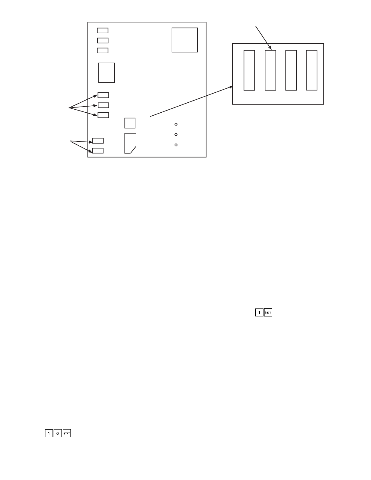
Adiagram of the CPM board is shown in Fig. 1. There are
line voltage inputs at L1, L2, and L3. Below these inputs are
the current toroid inputs at Plug 1. Below Plug 1 are the 3
COMM3 communication terminals. In the lower left corner
of the board are the inputs for motor winding temperature.
The address DIP (dual-in-line package) switch and compressor must-trip amps header are factory set. For compressor A1, switches 2 and 4 should be set. For compressor A2
(30HXA,C206-271AND 30GX205-265), switches 2, 3, and
4 should be set. For compressor B1, switches 1 and 4 should
be set.
T overifypropermusttripampsheaderconfiguration,press
and use the up arrow key on the HSIO to locate the
must trip amp values. Press the reset button on the HSIO/
fuse panel to update these values. See Appendix A. If the
values do not match those in Appendix A, verify with Appendix D that the configuration headers have been properly
punched out.
4
Page 5
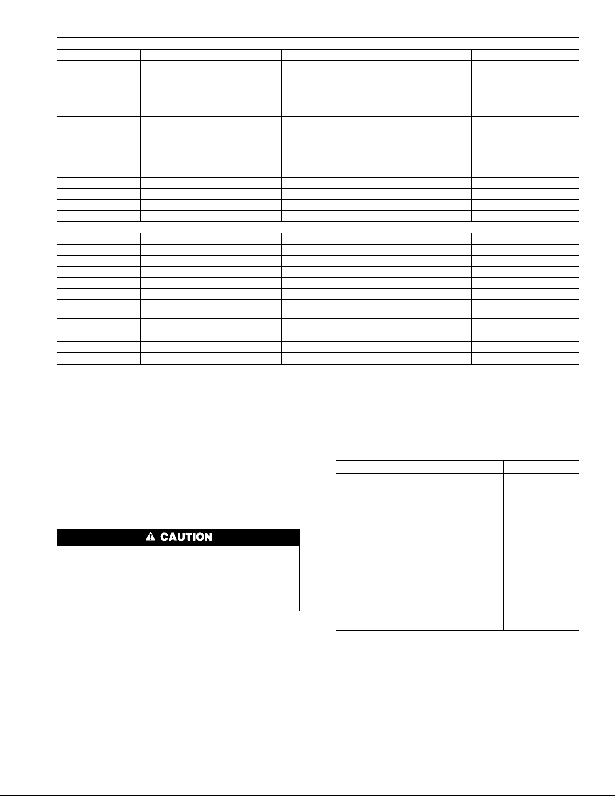
Table 2 — Thermistor and Transducer Locations
THERMISTORS
Sensor Description Location Connection Terminals
T1 Cooler Leaving Fluid Temp Cooler Head Leaving Fluid Side PSIO-2, J7 pins 2,3
T2 Cooler Entering Fluid Temp Cooler Head Entering Fluid Side PSIO-2, J7 pins 5,6
Motor Temp A1 Motor Temperature A1 Compressor A1 Junction Box CPM-A1, T terminals
Motor Temp A2* Motor Temperature A2 Compressor A2 Junction Box CPM-A2, T terminals
Motor Temp B1 Motor Temperature B1 Compressor B1 Junction Box CPM-B1, T terminals
T5 Discharge Gas TempA Top of Condenser Circuit A (30HXC Only) PSIO-2, J7 pins 8,9
Top of Oil Separator Circuit A (All Other Units)
T6 Discharge Gas Temp B Top of Condenser Circuit B (30HXC Only) PSIO-2, J7 pins 11,12
Top of Oil Separator Circuit B (All Other Units)
LL-A (T3) Liquid Level Circuit A Top of Cooler Circuit A PSIO-1, J7 pins 5,6
LL-B (T4) Liquid Level Circuit B Top of Cooler Circuit B PSIO-1, J7 pins 8,9
T7 (optional)† Outdoor Air Thermistor Outside Air Stream PSIO-2, J7 pins 20,21
STP (optional)† Space Temperature Conditioned Space PSIO-2, J7 pins 23,24
T8 (optional)† Condenser Entering Water Temp Condenser Entering Fluid Line PSIO-2, J7 pins 14,15
T9 (optional)† Condenser Leaving Water Temp Condenser Leaving Fluid Line PSIO-2, J7 pins 17,18
PRESSURE TRANSDUCERS
Sensor Description Location Connection Terminals
DPT-A Discharge Pressure Circuit A Top of Condenser Circuit A (30HXC Only) PSIO-1, J7 pin 22
Top of Oil Separator Circuit A (All Other Units)
SPT-A Suction Pressure Circuit A Top of Cooler Circuit A PSIO-1, J7 pin 19
EPT-A Economizer Pressure Circuit A Economizer Line Entering Comp A PSIO-1, J7 pin 10
OPT-A1 Oil Pressure Compressor A1 Compressor A1 Oil Connection PSIO-1, J7 pin 25
OPT-A2* Oil Pressure Compressor A2 Compressor A2 Oil Connection PSIO-1, J7 Pin 1
DPT-B Discharge Pressure Circuit B Top of Condenser Circuit B (30HXC Only) PSIO-1, J7 pin 16
Top of Oil Separator Circuit B (All Other Units)
SPT-B Suction Pressure Circuit B Top of Cooler Circuit B PSIO-1, J7 pin 31
EPT-B Economizer Pressure Circuit B Economizer Line Entering Comp B PSIO-1, J7 pin 13
OPT-B Oil Pressure Compressor B Compressor B1 Oil Connection PSIO-1, J7 pin 28
*30HX206-271 only.
†Sensors are available as accessories for field installation.
The CPM communicates on the COMM3 communication
bus to the PSIO-1 module. Proper operation of theCPMboard
can be verified by observing the 3 LEDs (light-emitting diodes) located on the board. The top LED is red and blinks
at a rate of once every 1 to 2 seconds. This indicates that the
module is powered and operating correctly.ThemiddleLED
is yellow and blinks when there is an automatic reset alarm
condition. The yellow LED remains on and does not blink
for manual reset alarm conditions. The bottom LED is green
and blinks when the module is satisfactorily communicating
with the PSIO-1 module. The CPM communicates the status
of its inputs and outputs, and reports 18 different alarm conditions to the PSIO-1. The alarms are listed in Table 3.
The CPM module has many features that are specifically designed to protect the compressor, including reverse rotation protection. Do not attempt to bypass or
alter any of the factory wiring. Any compressor operation in the reverse direction will result in a compressor
failure that will require compressor replacement.
The PSIO-1 will generate an alert when it receives an alarm
input from the CPM. The alert will be generated in a y.xx
format, where ‘‘y’’ refers to the compressor and ‘‘xx’’ to the
alarm value in Table 3 (decimal point removed). For example, the HSIO might displayAlarm 1.70 for a voltage phase
reversal occurring on compressor A1. Similarly, the display
would read 5.85 for a motor overtemperature condition on
compressor B1.AlertsforcompressorsA2 and B2 (if present)
would be generated as ‘‘2.xx’’and ‘‘6.xx,’’respectively. Alarm
codes 3 and 4 would not be used. Ending zeros are not
displayed.
The high-pressure switch is wired in series with the relay
coils of the 4 relays on the CPM. If this switch opens during
operation, all relays on the CPM are deenergized and the
compressor is stopped. The failure is reported to the PSIO-1
and the processor module locks off the compressor from restarting until the alarm is manually reset.
Table 3 — Compressor Protection Module
Feedback Codes
ALARM CONDITION VALUE
High Pressure Switch Trip 1.0
No Motor Current 2.0
Current Imbalance Alarm 10% 2.5
Current Imbalance Warning 10% 2.7
Current Imbalance 18% 3.0
Single Phase Current Loss 3.5
High Motor Current 4.0
Ground Fault 5.0
Voltage Imbalance Alarm 3% 5.5
Voltage Imbalance Warning 3% 5.7
Voltage Imbalance 7% 6.0
Voltage Phase Reversal 7.0
Contactor Failure 7.5
Current Phase Reversal 8.0
Motor Overtemperature 8.5
Open Thermistor 9.0
Configuration Header Fault 9.5
Shorted Thermistor 10.0
No Error 0
Wye-Delta vs Across-the-line (XL) Starting
Option —
All 30GX,HX chillers operating at voltages of
208/230-3-60 or 230-3-50 (5 or 8 at Position 12 in model
number) are supplied with factory installed Wye-Deltastarters. All other voltage options can be ordered with either
Wye-Delta or XL starting options. The XL starting method
is the most cost effective and simply starts the compressor
motor in a Delta configuration (the motors are designed for
continuous operation in this configuration) using a single contactor. See Fig. 2. This is the simplest starting method to use
and is ideal where starting current does not require limiting.
5
Page 6
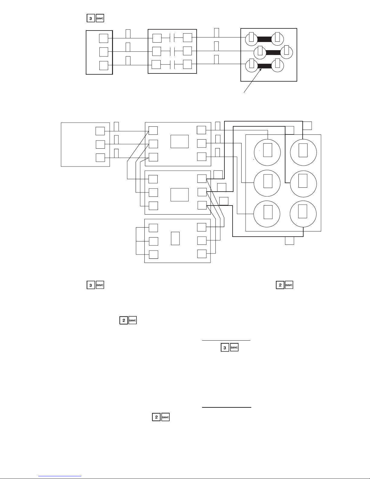
Where current limitations exist, the Wye-Deltaoptionmay
be used. See Fig. 3. This option uses a factory-installed starter
assembly for each compressor, which consists of 3 contactors labelled 1M, 2M, and S. As the compressor is started,
the CPM module energizes contactors 1M and S, which connects and energizes the motor windings in a Wye configuration. The starting current required will be approximately
60% less than that required for an XL start due to the higher
impedance of the motor windings when Wye connected. The
compressor will attain about 100% of its normal operating
speed (approximately 3 to 6 seconds) before the CPM module deenergizes the S contactor and energizes the 2M contactor, switching the compressor windings to a Delta wiring
configuration. The S and 2M contactors in the starter assembly are both mechanically and electrically interlocked so that
they will not both be energized at the same time.
Do not alter the factory-installed power wiring from the
control box terminal block to the compressor junction block.
Doing so will cause permanent damage to the compressor
and will require that the compressor be replaced.
Capacity Control — The control system cycles com-
pressors, loaders, and minimum load control valves to maintain the user-configured leaving chilled fluid temperature set
point. Entering fluid temperature is used by the microprocessor to determine the temperature drop across the cooler and
is used in determining the optimum time to add or subtract
capacity stages. The chilled fluid temperature set point can
be automatically reset by the return temperature reset or space
and outdoor-air temperature reset features. It can also be reset from an external 4 to 20 mA signal (requires fieldsupplied 500-ohm,1⁄2watt resistor), or from a network signal.
The capacity routine runs every 30 seconds. The routine
attempts to maintain the Control Point at the desired set point.
Each time it runs, the control reads the entering and leaving
fluid temperatures. The control determines the rate at which
conditions are changing and calculates 2 variables based on
these conditions. Next, a capacity ratio (Load/Unload Fac-
tor under ) is calculated using the 2 variables to
determine whether or not to make any changes to the current
stages of capacity. This ratio value ranges from − 100 to
+ 100%. If the next stage of capacity is a compressor, the
control starts (stops) a compressor when the ratio reaches
+ 100% (− 100%). If the next stage of capacity is a loader,
the control energizes (deenergizes) a loader when the ratio
reaches + 60% (− 60%). Loaders are allowed to cycle faster
than compressors, to minimize the number of starts and stops
on each compressor.Adelay of 90 seconds occurs after each
capacity step change.
MINUTES LEFT FOR START — This value is displayed in
the Status subfunction and represents the amount of time to
elapse before the unit is started. This value can be zero without the machine running in many situations. This can include being unoccupied, LOR switch in the OFF position,
CCN not allowing unit to start, Demand Limit in effect, no
call for cooling due to no load, and alarm or alert conditions
present. If the machine should be running and none of the
above are true, a minimum off time may be in effect. The
machine should start normally once the time limit has
expired.
MINUTES OFF TIME ( ) — This user configurable time period is used by the control to determine how
long unit operation is delayed after power is applied/
restored to the unit. It is also used to delay compressor restarts after the unit has shut off its lowest stage of capacity.
Typically, this time period is configured when multiple machines are located on a single site. For example, this gives
the user the ability to prevent all the units from restarting at
once after a power failure. A value of zero for this variable
does not mean that the unit should be running.
LOADING SEQUENCE — The 30GX,HX chiller efficiency is greatest at full load. Therefore, the following sequence list applies to capacity control.
1. Thenextcompressor is not started until all others are running at 100%.
2. The second unloading stage is only used during initial
capacity staging of the unit at start-up.
3. Whenever a compressor is started in a circuit, the loaders
in the circuit are deenergized for 15 seconds before the
compressor is started. The loaders are energized 90 seconds after the compressor is started.
L1
L2
L3
CURRENT TOROID
INPUT PLUG
1
2
3
T
T
TEMPERATURE
ADDRESS DIP
SWITCH
COMM3
24/115/230 VAC
INPUTS/OUTPUTS
COMPRESSOR PROTECTION MODULE (CPM)
COMPRESSOR
MUST TRIP
AMPS HEADER
1
2
RED LED
YELLOW LED
GREEN LED
MOTOR INPUT
PUSH THIS SIDE OF SWITCH
DOWN TO SET ADDRESS
1234
ROCKER DOWN
1
0
2
3
4
5
Fig. 1 — Compressor Protection Module
LED — Light-Emitting Diode
NOTES:
1. The red LED blinks continuously when the module
is operating properly.
2. The yellowLEDblinks during automaticreset alarm,
and is continuously lit when the manual reset alarm
is active.
3. The green LID blinks continuously when communicating properly with PSIO-1.
6
Page 7
CLOSE CONTROL( ) — When configured for Close
Control, the control is allowed to use any loading/capacity
control devices required to maintain better leaving fluid temperature regulation.Allstagesofunloadingareavailable.See
Appendix B for an example.
LEAD/LAG DETERMINATION ( ) — This is a configurable choice and is factory set to be automatic. The value
can be changed to Circuit A or Circuit B leading, as desired.
Set at automatic, the control will sum the current number of
logged circuit starts and one-quarter (Version 3.0 and later)
of the current operating hours for each circuit. The circuit
with the lowest sum is started first. Changes to which circuit
is the lead circuit and which is the lag are made when shutting off compressors.
On 30HX206-271 and 30GX205-265 units set for staged
loading, the control fully loads the lead circuit before starting the lag circuit and unloads the lag circuit first. When these
units are set for equal loading, the control maintains nearly
equal capacities in each circuit when the chiller is loading
and unloading.
CAPACITY SEQUENCE DETERMINATION ( ) —
This is configurable as equal circuit loading or staged circuit
loading with the default set at staged. The control determines the order in which the steps of capacity for each circuit are changed. This control choice does NOT have any
impact on machines with only 2 compressors.
MINIMUM LOAD VALVE ( ) — When this option
is installed and configured, the first stage of capacity is initiated by energizing the Minimum Load valve relay.The control energizes loaders as needed thereafter. Similarly, the
Minimum Load valve relay will be energized forthelaststage
of capacity to be used before the circuit is shut down.
CAPACITY CONTROLOVERRIDES—The following overrides will modify the normal operation of the routine.
Deadband Multiplier — The user configurableDeadbandMultiplier ( ) has a default value of 1.0. The range is from
1.0 to 4.0. When set to other than 1.0, this factor is applied
to the capacity Load/Unload Factor. The larger this value is
set, the longer the control will delay between adding or removing stages of capacity. Figure 4 shows how compressor
starts can be reduced over time if the leaving water temperature is allowed to drift a larger amount above and below the
set point. This value should be set in the range of 3.0 to 4.0
for systems with small loop volumes.
First Stage Override — If the current capacity stage is zero,
the control will modify the routine with a 1.2 factor on adding the first stage to reduce cycling. This factor is also applied when the control is attempting to remove the last stage
of capacity.
L1
L2
L3
T1
T1
T3
3
2
1
1
2
3
4
6
5
COMPRESSOR JUNCTION BOX
JUMPER BARS
COMPRESSOR CONTACTOR
1
2
3
21
22
23
TERMINAL BLOCK
Fig. 2 — Across-the-Line (XL) Compressor Wiring
1
2
3
4
5
6
1
2
3
T1
T1
T1
T2
T2
T2
T3
T3
T3
S
2M
1M
L3
L3
L3
L2
L2
L2
L1
L1
L1
1
2
3
22
21
23
TERMINAL BLOCK
COMPRESSOR STARTER ASSEMBLY
COMPRESSOR JUNCTION BOX
21
22
23
4
6
5
Fig.3—Wye-Delta Compressor Wiring
7
Page 8

Slow Change Override —The control prevents the capacity
stages from being changed when the leaving fluid temperature is close to the set point (within an adjustable deadband)
and moving towards the set point.
Ramp Loading ( ) —Limitstherate of change of leaving fluid temperature. If the unit is in a cooling mode and
configured for Ramp Loading, the control makes 2 comparisons before deciding to change stages of capacity. The control calculates a temperature difference between the control
point and leaving fluid temperature. If the differenceisgreater
than 4° F (2.2° C) and the rate of change (°F or °Cperminute)
is less than the configured Cooling Ramp Loading value
( ), the control does not allow any changes to the
current stage of capacity.
Low Entering Fluid Temperature Unloading — When the
entering fluid temperature is below the control point, the control will attempt to remove 25% of the current stages being
used. If exactly 25% cannot be removed, the control removes an amount greater than 25%, but no more than necessary. The lowest stage will not be removed.
Low Discharge Superheat — If a circuit’s discharge superheat is less than 15° F (8.3° C), the control does not increase
the current capacity stage and the EXD is not opened any
further. If the discharge superheat is less than 10° F
(5.6° C) and decreasing, the EXD is closed 50 steps every
10 seconds. If the discharge superheat is less than
5° F (2.8° C) and decreasing, the circuit is unloaded every
30 seconds until the superheat is greater than 5° F
(2.8° C). The final capacity stage is not unloaded unless an
alarm condition exists. This override is ignored for the first
3 minutes after a compressor is started.
Low Saturated Suction Temperature — To avoid freezing
the cooler,thecontrol will compare the circuit Saturated Suction temperature with a predetermined freeze point. For water circuits, the freeze point is 28 F (−2.2 C). For brine circuits, the freeze point is 8° F (4.4° C) below the cooling set
point (lower of 2 cooling set points for dual configuration).
If the saturated suction temperature is below the freeze point,
the unit capacity is not allowed to increase. For brine cir-
cuits, the freeze point can be entered by pressing
and scrolling 12 items down. The control will use the Brine
Freeze Point value less 6°F (3.3°C) as the freeze point to
compare with the Saturated Suction temperature. The default for the Brine Freeze Point is 34 F (1.1 C) which means
the control will use 28 F (−2.2 C) as the freeze point. This
value is adjustable from −15 F to 34 F (−26.1 to 1.1 C). For
water (brine) circuits, if the Saturated Suction temperature
falls below 34 F (1.1 C) (the Brine Freeze Point), the unit
capacity will not increase. If the Saturated Suction temperature falls below 28 F (−2.2 C), the Brine Freeze Point minus
6° F (3.3° C), for 90 seconds, all loaders in the circuit are
turned off. If this condition continues for a total of 3 minutes, the circuit will shut down.
High Condensing Temperature Unloading — Every 10 seconds the control checks for the conditions below. Loaders
will be cycled as needed to control the saturated condensing
temperature below the configured maximum condensing temperature. Configured maximums are 154 F (67.8 C) for30GX,
152 F (66.7 C) for 30HXA, and 122 F (50 C) for 30HXC
units. If a circuit’s saturated condensing temperature is more
than 12° F (6.7 C) below the maximum condensing temperature, the circuit capacity is not allowed to increase. If
the saturated condensing temperature is more than 2° F
(1.1° C) above the maximum condensing temperature for
60 seconds, a loader is turned off. If the saturated condensing
temperature rises to more than 5° F (2.8° C) above the maximum condensing temperature during the 60 seconds, a loader
is turned off immediately. If all the loaders were already off,
the compressor is shut down and an alarm is generated.
MOP(Maximum Operating Pressure) Override —Thecontrol monitors saturated condensing and suction temperature
for each circuit as well as differential oil pressure. Based
on a configurable maximum operating set point (saturated
suction temperature), set maximum condensing temperature, and minimum differential oil pressure, the control may
reduce the number of capacity stages being used and/or may
lower the EXD position when system pressures approach the
set parameters.
Head Pressure Control
GENERAL — The microprocessor controls the condenser
fans (30GX) or analog water valve (30HXC) to maintain the
saturated condensing temperature to a configurable set point.
The fans are staged or speed varied (30GX) or water valve
controlled (30HX) based on each circuit’s saturated condensing temperature and compressorstatus.Water cooled units
(30HXC) operating at less than 70 F (21.1 C) for entering
condenser water require the use of head pressure control.
The chiller must be field configured for the options shown
in Table 4. Fan stage settings are shown in Table 5.
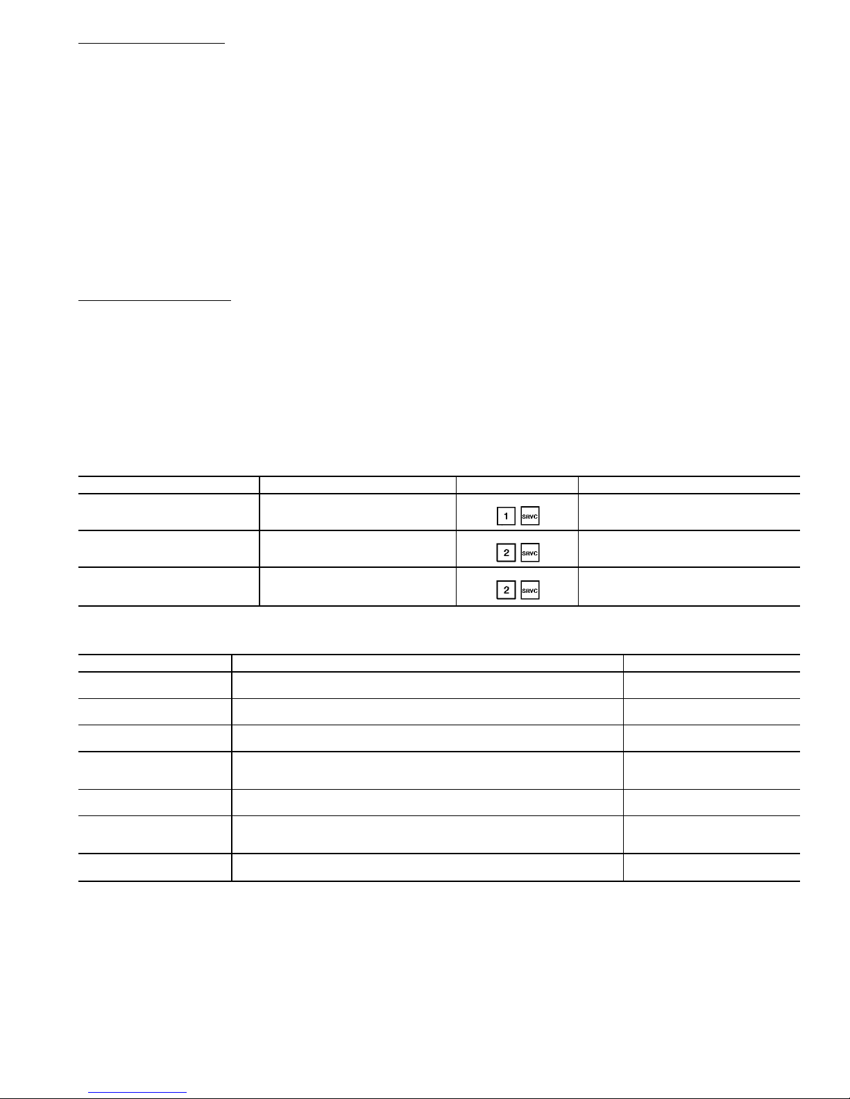
AIR COOLED UNITS (30GX) — See Fig. 5 for condenser
fan locations.
47
46
45
44
43
42
41
0 200 400 600 800 1000
TIME (SECONDS)
2 STARTS
3 STARTS
DEADBAND EXAMPLE
LWT (F)
MODIFIED
DEADBAND
STANDARD
DEADBAND
8
7
6
5
LWT (C)
LEGEND
LWT — Leaving Water
Temperature
Fig. 4 — Deadband Multiplier
8
Page 9
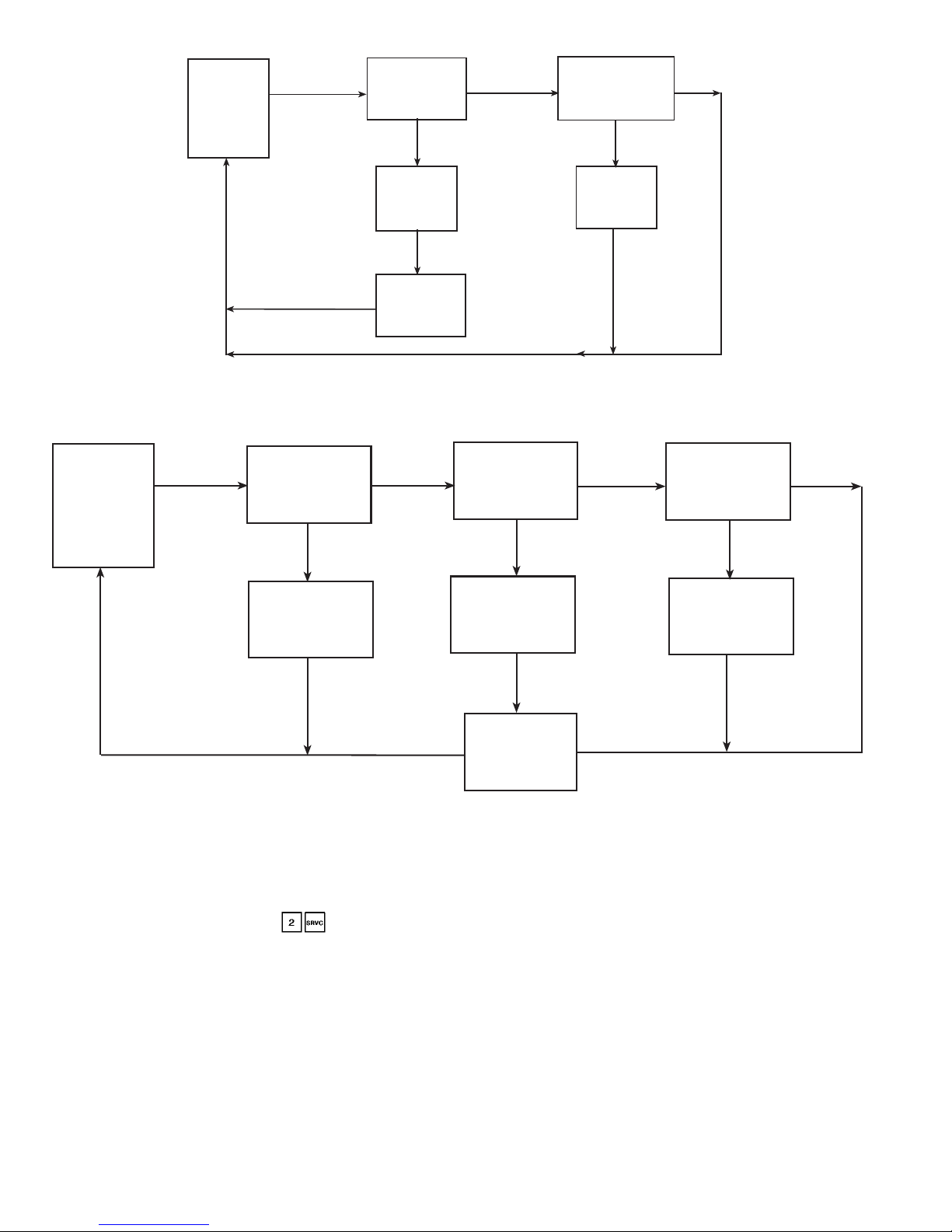
No Motormastert Control — The fans are controlled based
on Saturated Condensing Temperature. The first fan stage
for each circuit is turnedonwheneverthecompressoristurned
on.Afan stage is added when the Saturated Condensing Temperature (SCT) exceeds the Head Pressure Set Point. The
Head Pressure Set Point is configurable in the Set Point subfunction. The default is 113 F (45 C). Once a fan stage has
been added, the software temporarily modifies the head pressure set point by adding 15° F (8.3° C) for 35 seconds. A
fan stage will be removed when the Saturated Condensing
Temperature has been less than the Head Pressure Set Point
minus 35 F (19.4 C) for 2 minutes.Thecontrolusesthehigher
of the 2 Saturated Condensing Temperature values for
30GX080-150 and 160 units. For the 30GX151 and 161-265
units, each circuit’s fan stages are independently controlled
based on the circuit Saturated Condensing Temperature.
Refer to Table 6 for condenser fan control information. See
Fig. 6A.
With Motormaster Control — For low-ambient operation,
the lead fan in each circuit can be equipped with the optional
or accessory Motormaster III head pressure controller. This
controller can be used in one of 2 ways. If factory installed,
the controller will be configured for 4 to 20 mA control. With
the Motormaster III option enabled, the PSIO-1 module calculates the required output based on Saturated Condensing
temperature, Head Pressure set point, and a PID (proportional integral derivative) loop calculation. This 4 to
20 mA output is driven through the PSIO-2 module. To obtain this accessory for field installation, order by part number 30GX-900---012forasinglecontroller package (30GX080150 and 160). Order part number 30GX-900---014 for a
dual controller package (30GX151 and 161-265). These
packages contain all the hardware required to install the
accessory. See Fig. 6B.
The control will use the higher of the 2 Saturated Condensing Temperature values for 30GX080-150 and 160 units.
For the 30GX151 and 161-265 units, each circuit’s fan stages
are independently controlled based on the circuit Saturated
Condensing Temperature. Refer to Table6 for condenser fan
staging information.
WATER-COOLED UNITS (30HX) — The 30HX chillers
can be configured to control direct or reverse-acting water
valves that are controlled bya4to20mAsignal. A 2 to
10 VDC signal can be used by installing a 500-ohm resistor
across the 2 output terminals of the 4 to 20 mA signal. This
control scheme reads the saturated condensing temperature
and uses a PID (proportional integral deriative) loop to
control the head pressure. Proportional, Integral and Derivative gain parameters for both the water and air cooled controls are adjustable and can be found in the Service subfunction. Checkout and adjustment of the PID loop should
only be performed by certified Carrier Comfort Network
technicians.
Table 4 — Field Configured Chiller Options
CONFIGURATION OPTION DESCRIPTION HSIO LOCATION FACTORY CONFIGURED?
Fan Staging Select Air cooled staging method
Yes. See Table 5
Motormaster Control Select Applies to air cooled units only
Yes. 0 = None
Set to 1 to enable (Motormaster only)
Water Valve Type Applies to water cooled unit only
Yes. 0 = None
Setto1=4−20mA,2=0−10V,
3=20−4mA,4=10−0V
Table 5 — Fan Staging Settings for Air Cooled (30GX) Units
UNIT 30GX DESCRIPTION OPTION NUMBER
080-105
1st stage compressor status
2nd stage common control based on highest SCT
12
106-125
1st stage compressor status
2nd and 3rd stage common control based on highest SCT
14
136, 150, 160
1st stage compressor status
2nd through 4th stage common control based on highest SCT
16
151, 161, 175,
205, 225
1st stage each circuit, compressor status
2nd stage Circuit B independent
2nd and 3rd stage Circuit A independent
7
176
1st stage each circuit, compressor status
2nd and 3rd stage each circuit independent
3
206, 226, 250
1st stage each circuit, compressor status
2nd stage Circuit B independent
2nd, 3rd and 4th stage Circuit A independent
9
251, 265
1st stage each circuit, compressor status
2nd, 3rd and 4th stage each circuit independent
5
LEGEND
SCT — Saturated Condensing Temperature
9
Page 10
ADJUSTING PID ROUTINES — The 30GX and 30HXC
head pressure control routines use PID (proportional integral derivative) loops to maintain a user-configurable head
pressure set point. Gain default values are located in the Service function. See page 30. The current values can be read
under from the HSIO. The control calculates a new
fan speed (30GX) or water valve position (30HXC) every
5 seconds based on these gain values and an error term equal
to saturated condensing temperature minus head pressure set
point. If the control routine is not responding fast enough to
large changes (circuit starting, for example), increase the proportional term.
When the routine is making too great a change to valve
position or fan speed, decrease the proportional term.To minimize hunting, keep the integral term positive and as low as
possible. The default for the derivative term is zero. This
valve is used to control ‘‘droop,’’which is common in master/
submaster control schemes. The value should not need to be
changed.
Cooler and Condenser (30HXC) Pump Control
—
The 30GX and 30HX chillers can be configured forcooler
and condenser (30HXC) pump control. Inputs for a cooler
flow switch or interlock and condenser flow switch are also
provided.
COOLER PUMP CONTROL ( ) — The factory default setting for cooler pump control is ‘‘Not Controlled.’’
All chillers are enabled at the factory for cooler pump interlock. See page 71 of Field Wiring section for wiring of
cooler flow switch and/or cooler pump interlock contacts.
Whether cooler pump control is enabled or not, the control
generates an alarm if this input does not close within one
minute after the unit switches to an occupied mode or the
cooler pump is turned on. See Alarms and Alerts section,
page 43 for a description of Alarms 53-55. If cooler pump
control is enabled, the control waits one minute and checks
the interlock or switch input before starting to determine if
cooling is needed. The cooler pump is turned on when the
chiller is in the occupied mode and turned offotherwise.The
cooler pump is turned on in either of two override conditions: If the cooler freeze protection alarm has been generated, the cooler pump is turned on if not already running. If
a cooler heater is being used and has been on for more than
15 minutes during saturated suction freeze protection, the
cooler pump is turned on.
1
2
3
4
CONTROL
BOX
END
5
6
7
8
9
10
CONTROL
BOX
END
4
2
1
3
CONTROL
BOX
END
13 5 7
24 6 8
CONTROL
BOX
END
4
6
1
3
5
2
5
CONTROL
BOX
END
7911
12
6810
4
2
3
1
CONTROL
BOX
END
1
3
5
7
2
4
6
8
CONTROL
BOX
END
14
12
10
13
11
9
1
3
5
7
2
4
6
8
9
11
12
10
Fig. 5 — 30GX Condenser Fan Locations
30GX080-105 30GX106-125
30GX151, 161, 175, 205, 225 30GX176
30GX206, 226, 250
30GX136, 150, 160
30GX251, 265
10
Page 11

Table 6 — 30GX080-265 Condenser Fan Staging (PSIO-1 Controlled)
30GX UNIT SIZE FAN TYPE FAN CONTACTOR FANS CONTROLLED FAN RELAY NO.*
080-105
Standard
FC-1 1, 2 5
FC-2 3, 4 1
High Static
FC-1, 1A 1, 2 5
FC-2, 2A 3, 4 1
106-125
Standard
FC-1 1, 2 5
FC-2 3, 4 1
FC-3 5, 6 2
High Static
FC-1, 1A 1, 2 5
FC-2, 2A 3, 4 1
FC-3, 3A 5, 6 2
136, 150,
160
Standard
FC-1 1, 2 5
FC-2 3, 4 1
FC-3 5, 6 2
FC-4 7, 8 2
High Static
FC-1, 1A 1, 2 5
FC-2, 2A 3, 4 1
FC-3, 3A 5, 6 2
FC-4, 4A 7, 8 2
151, 161, 175
205, 225
Standard
FC-1 1, 2 Comp. B1 contactor†
FC-2 3, 4 3
FC-3 5, 6 2
FC-4 7, 8 Comp. A1/A2 contactor†
FC-5 9, 10 1
High Static
FC-1, 1A 1, 2 Comp. B1 contactor†
FC-2, 2A 3, 4 3
FC-3, 3A 5, 6 2
FC-4, 4A 7, 8 Comp. A1/A2 contactor†
FC-5, 5A 9, 10 1
176
Standard
FC-1 1, 2 Comp. B1 contactor†
FC-2 3, 4 3
FC-3 5, 6 4
FC-4 7, 8 Comp. A1 contactor†
FC-5 9, 10 1
FC-6 11, 12 2
High Static
FC-1, 1A 1, 2 Comp. B1 contactor†
FC-2, 2A 3, 4 3
FC-3, 3A 5, 6 4
FC-4, 4A 7, 8 Comp. A1 contactor†
FC-5, 5A 9, 10 1
FC-6, 6A 11, 12 2
206, 226, 250
Standard
FC-1 1, 2 Comp. B1 contactor†
FC-2 3, 4 3
FC-3 5, 6 1
FC-4 7, 8 Comp. A1/A2 contactor†
FC-5 9, 10 2
FC-6 11, 12 2
High Static
FC-1, 1A 1, 2 Comp. B1 contactor†
FC-2, 2A 3, 4 3
FC-3, 3A 5, 6 1
FC-4, 4A 7, 8 Comp. A1/A2 contactor†
FC-5, 5A 9, 10 2
FC-6, 6A 11, 12 2
251, 265
Standard
FC-1 2, 4 1
FC-2 6, 8 2
FC-3 1 Comp B1 contactor†
FC-4 3 3
FC-5 5, 7 4
FC-6 9, 10 Comp. A1/A2 contactor†
FC-7 11, 12 2
FC-8 13, 14 2
High Static
FC-1, 1A 2, 4 1
FC-2, 2A 6, 8 2
FC-3 1 Comp. B1 contactor†
FC-4 3 3
FC-5, 5A 5, 7 4
FC-6, 6A 9, 10 Comp. A1/A2 contactor†
FC-7, 7A 11, 12 2
FC-8, 8A 13, 14 2
LEGEND
Comp. — Compressor
FC — Fan Contactor
*Fan Relay number displayed when using to test fans.
†Proper rotationof these fans tobe checked whencompressor(s) is running.SeeFig. 5 forcondenser fan locationswhen viewing
from the control box end.
11
Page 12
CONDENSER PUMP CONTROL ( ) — Factory defaults for both condenser pump control and condenser flow
switch are set to ‘‘Not Controlled’’and ‘‘Disabled,’’ respectively. The condenser pump can be controlled in one of two
ways: In the first method, the pump can be controlled like
the cooler pump — it is turned on whenever the machine is
in the on state and turned off otherwise (set to Type 1 using
the Service function). The second method of control is to
turn the pump on when the first compressor is started and off
when the last compressor is turned off (set to Type 2 using
the Service function). With the flow switched enabled, the
control checks the status of the input one minute after starting the pump. An alarm is generated if the flow switch input
is not closed.
READ CIRCUIT
SATURATED
CONDENSING
TEMPERATURE
AND CURRENT
FAN STAGE
IS SCT GREATER
THAN HEAD
PRESSURE
SET POINT?
INCREASE
CURRENT FAN
STAGE BY ONE
ADD 15° F TO
HEAD PRESSURE
SET POINT FOR
NEXT 35 SECONDS
DECREASE
CURRENT FAN
STAGE BY ONE
HAS SCT BEEN 35° F
LESS THAN HEAD
PRESSURE SET POINT
2 MINUTES?
NO
NO
YES
YES
LEGEND
SCT — Saturated Condensing Temperature
Fig. 6A — 30GX Head Pressure Control Without MotormasterT III Control
30GX UNITS — MOTORMASTER III CONTROL NOT INSTALLED
30GX UNITS — MOTORMASTER III CONTROL INSTALLED
DECREASE
CURRENT FAN
STAGE BY ONE
NO
NO
YES
IS SCT GREATER
THAN HEAD
PRESSURE SET
POINT PLUS 15F?
INCREASE
CURRENT FAN
STAGE BY ONE
YES
READ CIRCUIT
SATURATED
CONDENSING
TEMPERATURE
AND CURRENT
FAN STAGE
NO
INCREASE
CURRENT FAN
STAGE BY ONE
YES
CALCULATE NEW
PID VALUE. DOSE
OUTPUT REQUIRE
MORE FANS?
OUTPUT NEW mA
SIGNAL TO
CONTROLLER
DOES PID OUTPUT
REQUIRE LESS
FANS?
LEGEND
PID — Proportional Integral Derivative
SCT — Saturated Condensing Temperature
Fig. 6B — 30GX Head Pressure Control With Motormaster III Control
12
Page 13
Cooler Heater Control — Accessory cooler heaters
can be ordered for the 30GX chillers. If installed and enabled, these heaters are turned on only when the machine is
in the off state and the chiller is in a saturated suction temperature freeze condition.
Keypad and Display Module (Also Called
HSIO-II) —
This module allows the operator to communicate with the processor. It is used to enter configurations
and set points and to read data, perform tests, and set schedules. The device consists of a keypad with 7 function keys,
5 operative keys, 12 numeric keys (0 to 9, •, and -), and a
2-line, 24-character alphanumeric liquid crystal display. See
Fig. 7.
ACCESSING FUNCTIONS AND SUBFUNCTIONS —
Table 7 shows a brief description of the keypad buttons.
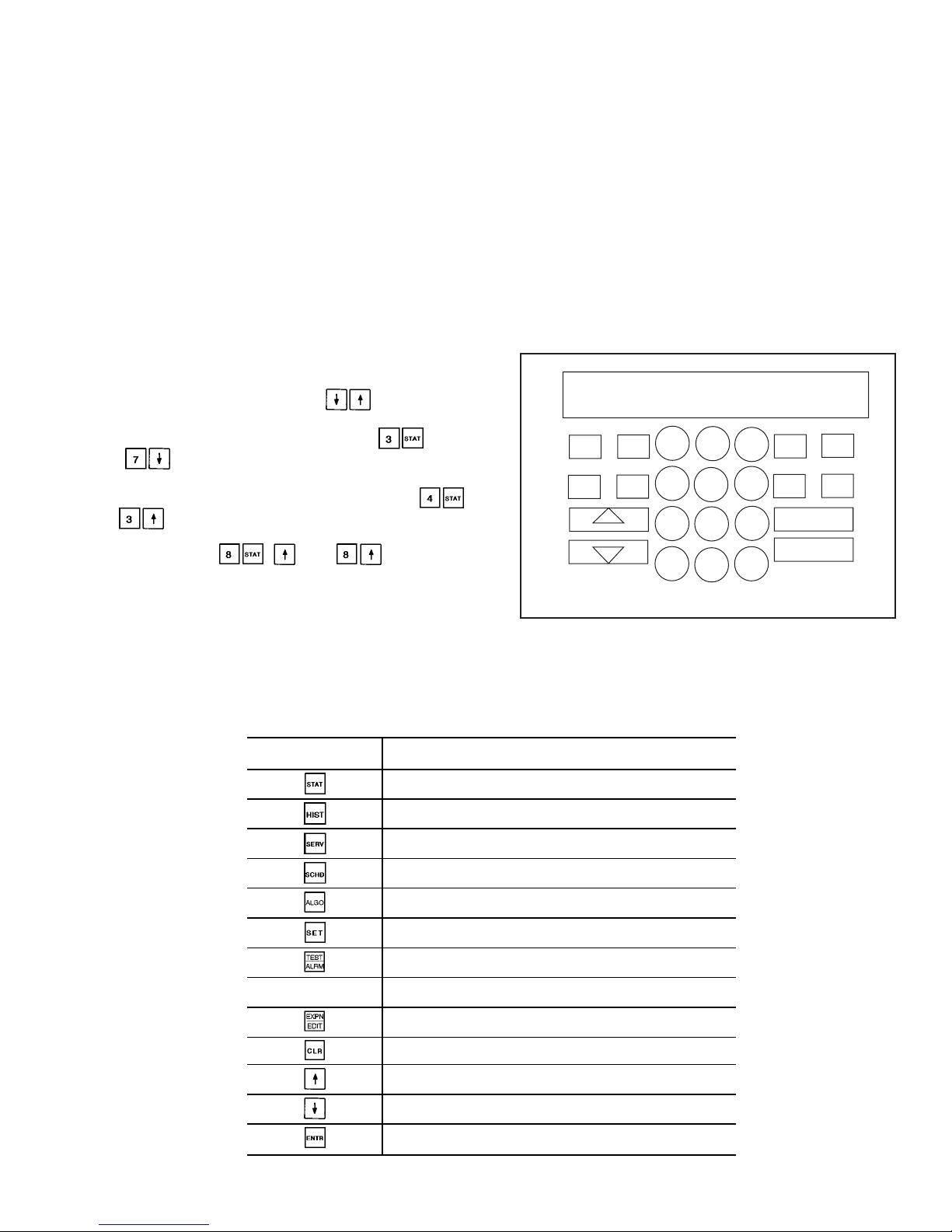
Table 8A shows the 6 functions (identified by name) and the
subfunctions (identified by number). Table 8B shows the 6
functions (identified by name) and the subfunctions (identified by number) when using the optional LID-2B controller. Table 9 shows a brief example on how to access
subfunctions.
NOTE: It is not necessary to use the through every
item in a subfunction. For example, if you wanted to read
the oil pressure for the A1 compressor, press , then
press to go directly to A1 Oil Pressure. Use a simi-
lar procedure to view an item near the bottom of a subfunction. To view the Circuit A Oil Switch status, press
and . Use a similar procedure to view an item near
the bottom of a subfunction. Toview Condenser Pump Flow
Switch status, press , , and . This proce-
dure is available in all functions except the TEST function.
AUTOMATIC DEFAULT DISPLAY — When the keypad
has not been used for 10 minutes, the display automatically
switches to the rotating automatic default display. This display contains the 5 parts shown below.
Entering Fluid Temp
xx.x° F
Leaving Fluid Temp
xx.x° F
Percent Total Capacity
xxx.x%
Total Number of Alarms
xx
MODES : MODE_TBL
Current active modes
All functions are made up of a group of subfunctions. To
enter a subfunction, first press the subfunction number desired. Then press the function key in which the subfunction
resides. To move within that subfunction, press the up or
down arrow keys. Another subfunction may be entered at
any time by pressing the subfunction number, then the function key. Depending on system type and configuration, all
displays may not be shown.
Table 7 — Keypad and Display Module Usage
FUNCTION
KEYS
USE
STATUS — For displaying diagnostic codes and
current operating information about the machine.
HISTORY — For displaying run time, cycles, and
previous alarms.
SERVICE — For entering specific unit configuration
information and enabling manual control function.
SCHEDULE — For entering occupied/unoccupied
schedules for unit operation.
ALGORITHM — Not used.
SET POINT — For entering operating set points
and day/time information.
TEST — For testing operating of the analog and
discrete outputs.
OPERATIVE
KEYS
USE
EXPAND — For displaying a non-abbreviated
expansion of the display.
CLEAR — For clearing the screen of all displays.
UP ARROW — For returning to previous display
position.
DOWN ARROW — For advancing to next display
position.
ENTER — For entering data.
CLEAR
ENTER
1
2
3
4
5
6
7
8
9
0
.
-
STAT
SET
SCHD
EXPN
EDIT
SRVC
HIST
ALGO
TEST
ALRM
TWENTY-FOUR CHARACTER
TWO-LINE LCD DISPLAY
LEGEND
LCD — Liquid Crystal Display
Fig. 7 — Keypad and Display Module
13
Page 14

Table 8A — HSIO Functions and Subfunctions
SUBFUNCTION
NO.
FUNCTIONS
Status
Test Schedule Service History Set Point
1
Alarm
Display
Circuit A
Discrete Outputs
Ice Build
Occupancy
Schedule
Factory
Configuration
Operating Hours Set Points
2
General Parameters
Display
Circuit B
Discrete Outputs
Local/Normal
Occupancy
Schedule
Options
Configuration 1
Alarm History English/Metric
3
Circuit A
Analog Values
Unit
Discrete Outputs
Remote CCN
Occupancy
Schedule
Options
Configuration 2
— Bus Address
4
Circuit A
Discrete Inputs/
Outputs Table
Valves and
MotormasterT
Control
Holiday 01
Configuration
Reset/Demand Limit
Configuration
— Time/Date
Configuration
5
Circuit B
Analog Values
— Holiday 02
Configuration
Machine
Configuration
Codes
— CCN
Enable/Disable
6
Circuit B
Discrete Inputs/
Outputs Table
— Holiday 03
Configuration
———
7
Unit Analog
Parameters
— Holiday 04
Configuration
Transducer
Calibration
——
8
Miscellaneous
Inputs/Outputs
— Holiday 05
Configuration
Manual Control — —
9
Operating Modes — Holiday 06
Configuration
Master/Slave
Configuration
——
10
Capacity Control — Holiday 07
Configuration
———
11
Dual Chiller — Holiday 08
Configuration*
———
*Subfunctions through are for configuring Holidays 09 through 30.
14
Page 15
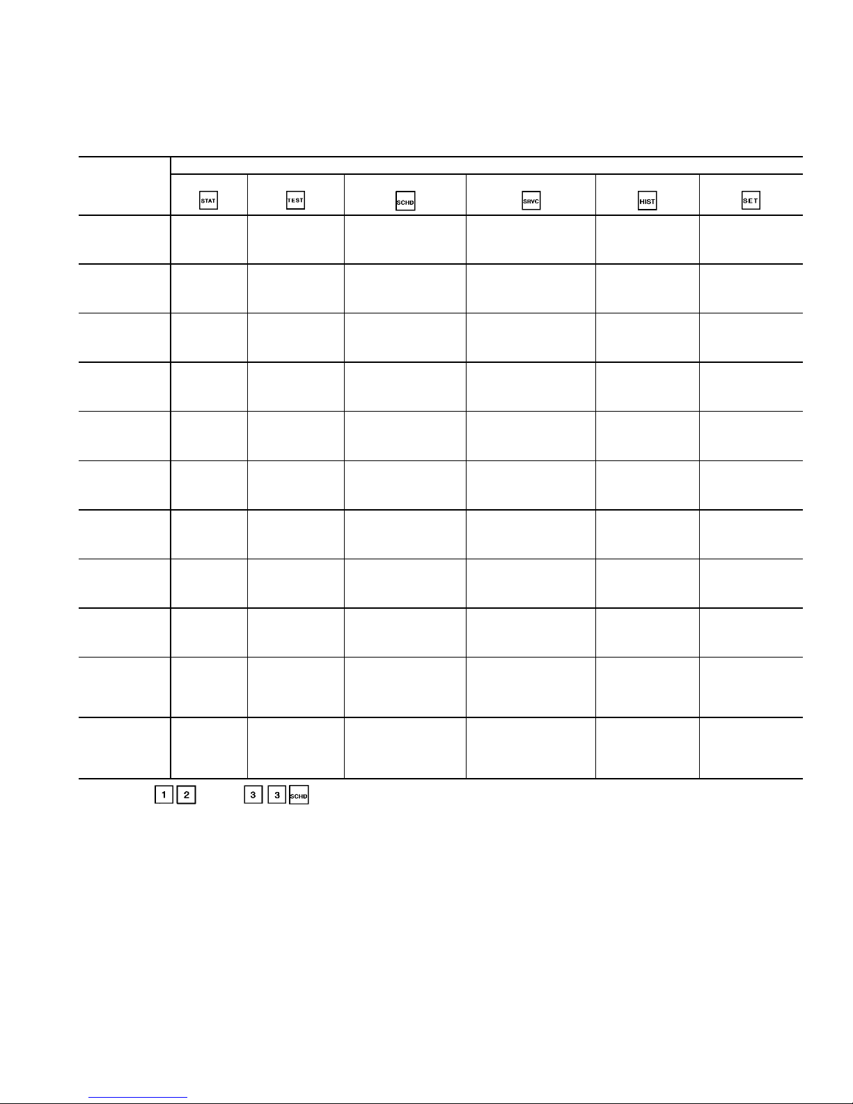
Table 8B — Functions and Subfunctions Cross-Reference for the Optional LID-2B Controller
The optional LID-2B controller cross reference table below can be used as a guide to access the same information
outlined in the HSIO functions and subfunctions table (see
Table 8A). For example, in Table 8A, the alarm history is
accessed through the HSIO by pressing 2 and the History
button on the keypad (see Table 7). The LID-2B cross
reference table lists the menu item from the LID-2B which
contains the alarm history information. In another example,
from Table 8A, pressing 3 and the Status button on the HSIO
keypad will access the circuit A analog values. In the table
below, the circuit A analog values are accessed by selecting
STATUS CIRCA_AN from the appropriate LID-2B menu.
HSIO
SUBFUNCTION
NO.
HSIO FUNCTION KEY
Status
Test Schedule Service History Set Point
1
STATUS
A_UNIT_1
SERVICE
CONTROL TEST
SCHEDULE
OCCPC012
SERVICE
EQUIPMENT
CONFIGURATION
SERVICE
EQUIPMENT
CONFIGURATION
STRTHOUR
SETPOINT
2
STATUS
A_UNIT_1
SERVICE
CONTROL TEST
SCHEDULE
OCCPC02S
SERVICE
EQUIPMENT
CONFIGURATION
OPTIONS1
SERVICE
ALARM HISTORY
SERVICE
LID
CONFIGURATION
3
STATUS
CIRCA_AN
SERVICE
CONTROL TEST
SCHEDULE
OCCPC65S
SERVICE
EQUIPMENT
CONFIGURATION
OPTIONS2
—
SERVICE
CONTROLLER
IDENTIFICATION
4
STATUS
CIRA_DIO
SERVICE
CONTROL TEST
SERVICE
EQUIPMENT
CONFIGURATION
HOLIDAY,HOLDY_01
SERVICE
EQUIPMENT
CONFIGURATION
RESETCON
—
SERVICE
TIME AND DATE
5
STATUS
CIRCB_AN
—
SERVICE
EQUIPMENT
CONFIGURATION
HOLIDAY,HOLDY_02
SERVICE
EQUIPMENT
CONFIGURATION
CONCODES
—
STATUS
A_UNIT_1
6
STATUS
CIRB_DIO
—
SERVICE
EQUIPMENT
CONFIGURATION
HOLIDAY,HOLDY_03
———
7
STATUS
UNIT_2
—
SERVICE
EQUIPMENT
CONFIGURATION
HOLIDAY,HOLDY_04
SERVICE
EQUIPMENT SERVICE
CALIBRTE
——
8
STATUS
UNIT_3
—
SERVICE
EQUIPMENT
CONFIGURATION
HOLIDAY,HOLDY_05
SERVICE
EQUIPMENT SERVICE
MAN_CTRL
——
9
STATUS
MODE_TBL
—
SERVICE
EQUIPMENT
CONFIGURATION
HOLIDAY,HOLDY_06
SERVICE
EQUIPMENT
CONFIGURATION
MSTR_SLV
——
10
SERVICE
CONTROL
ALGORITHM
STATUS
LOADFACT
—
SERVICE
EQUIPMENT
CONFIGURATION
HOLIDAY,HOLDY_07
———
11
SERVICE
CONTROL
ALGORITHM
STATUS
LEADLAG
—
SERVICE
EQUIPMENT
CONFIGURATION
HOLIDAY,HOLDY_08*
——
—
*Subfunctions through are for configuring Holidays 09 through 30, and are also found under Service, Equipment
Configuration.
NOTE: The optional LID-2B controller uses the same password (1111) as the HSIO.
15
Page 16
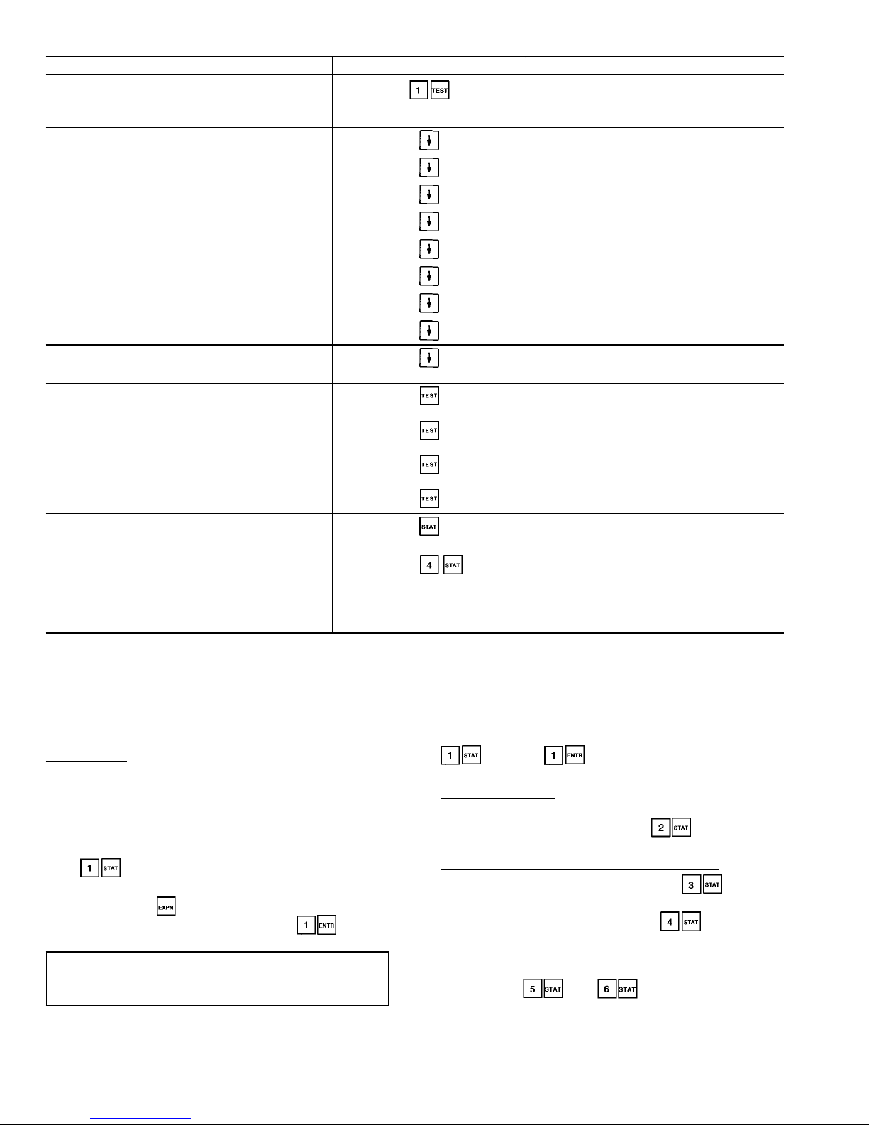
Table 9 — Accessing Functions and Subfunctions
OPERATION KEYPAD ENTRY DISPLAY RESPONSE
To access a function, press
subfunction no. and function
name key. Display shows subfunction group.
Circuit A Discrete Outputs
Loader A1
Relay is OFF
To move to other elements,
scroll up or down using arrow keys.
Loader A2
Relay is OFF
Minimum Load Valve A
Relay is OFF
Circuit A Oil Heater
Relay is OFF
A1 Mtr. Cooling Solenoid
Relay is OFF
A2 Mtr. Cooling Solenoid
Relay is OFF
Circuit A Oil Pump
Relay is OFF
Oil Solenoid A1
Relay is OFF
Oil Solenoid A2
Relay is OFF
When the last element in a
subfunction has been displayed,
the first element is repeated.
Loader A1
Relay is OFF
To move to next subfunction
it is not necessary to use
subfunction number. Press
function name key to
advance display through all
subfunctions within a
function and then back
to the first.
Circuit B Discrete Outputs
Loader B1
Relay is OFF
Unit Discrete Outputs
Valves and Motor Master
Circuit A Discrete Outputs
To move to another function,
either depress function name
key for desired function
(display shows the first
subfunction),
or
Access a specific subfunction by using the subfunction number and the
function name key.
Alarms : xx
Reset Alarms : 1 <ENTER>
CIR. A DISCRETE OUTPUTS
STATUS FUNCTION — This function shows the rotating
display, current status of alarm and alert (diagnostic) codes,
capacity stages, operating modes, chilled water set point, all
measured system temperatures and pressures, analog inputs,
and switch inputs. Refer to Table 10 for a complete description of the function.
Alarms/Alerts — Alarms and alerts are messages that one
or more faults have been detected. The alarms and alerts indicate failures that cause the unit to shut down, terminate an
option (such as reset) or result in the use of a default value
such as a set point. Refer to the Troubleshooting section for
more information.
Up to 10 alarms/alerts can be stored at once. Toviewthem,
press . The control will display the current total
number of alarms/alerts. Use the arrow keys to scroll through
the list. Press the key when needed to view the full
description of an alarm or alert. Press to clear
all the alarms. See Table 11.
IMPORTANT: Do not clear the alarms without first
reviewing the full list and investigating and correcting
the cause of the alarms.
When an alarm or alert is stored in the display and the
machine automatically resets, the alarm/alert is deleted. Codes
for safeties which do not automatically reset are not deleted
until the problem is corrected and the machine is reset. To
clear manual reset alarms from the CPM modules, the reset
button on the HSIO bracket must be pressed. Next, switch
the LOR switch to OFF and back to Local or Remote
position (default alarm clearing method). Press
and then to clear the alarm from the PSIO
if the default LOR reset function has been disabled.
General Parameters — General operating parameters are
displayed including control mode, run status, CCN status,
and the 5 most current alarms. Press to display these
and the other values as shown in Table 10.
CircuitAand B Analog and Discrete Information —Circuit
A Analog Values can be viewed bypressing and scrolling down to see current system operating conditions such as
pressures and temperatures. Pressing will bring up
Circuit A Discrete Inputs and Outputs. Scroll down to view
the On/Off status of the compressor(s), loaders, solenoids,
and pumps. Oil switch and feedback inputs are also dis-
played. Press and to view the identical analog values and discrete inputs and outputs for Circuit B. See
Table 10 for a complete display.
16
Page 17
Unit Analog Parameters and Temperature Reset — Press
and scroll down to display the unit entering and leav-
ing fluid temperatures as well as the temperature reset signal
and calculated values.
Miscellaneous Inputs and Outputs — Pressing and
scrolling down will reveal the On/Off status of the con-
denser fans (30GX only). Also found here are the Demand
Limit settings, pump relay and switch status, and miscellaneous items such as Heat/Cool and Dual Set Point switch
positions. See Table 10 for a complete list.
Modes —Theoperatingmodesaredisplayed to indicate the
operating status of the unit at a given time. See Table 12 for
a complete list of all modes.
To enter the MODES subfunction, press and use
the key to view all current modes of operation. See
Table 13.
Capacity Control — Pressing , this subfunction displays the load/unload factor, control point, and leav-
ing water temperature. Scrolling down will also reveal the
liquid level sensor values in degrees format.
Dual Chiller — Pressing will access the dual
chiller control status. This subfunction will display whether
or not the chiller is operating as a Master or Slave, any alarm
conditions present for dual chiller control, and lead/lag information for changeover. Dual chiller control is configured
under .
17
Page 18
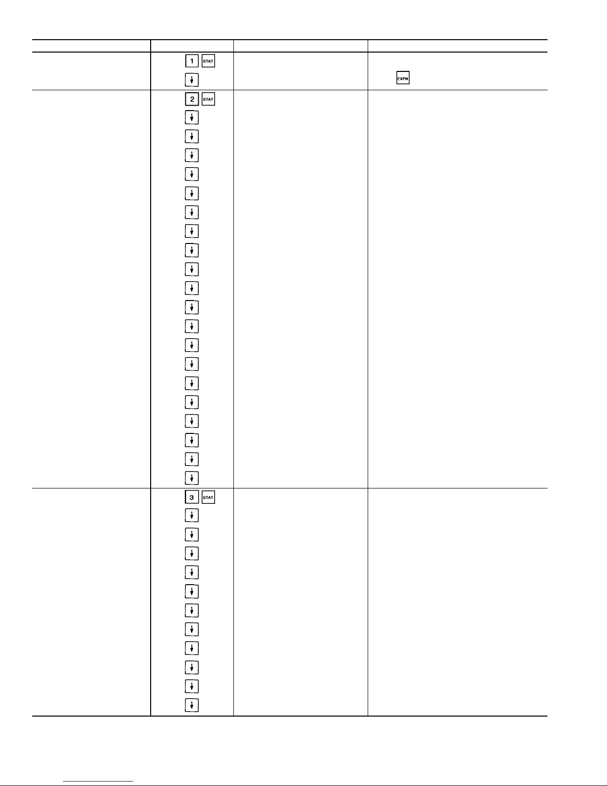
Table 10 — Status Function and Subfunction Directory
SUBFUNCTION KEYPAD ENTRY DISPLAY COMMENT
1 Alarms
Alarm : xx
Reset Alarms: 1 <ENTER>
All current alarms are displayed Use as needed
2 General Parameters GENERAL PARAMETERS
Displays LOCAL ON/OFF or CCN ON/OFF
Force/clear value with HSIO or CCN device.
Must be ON for CCN clock control.
Control Mode
Run Status
Off/On
Occupied ?
Yes/No
CCN Enable
Off/On
CCN Chiller Start/Stop
Start/Stop
Alarm State
Normal/Alarm
Current Alarm 1
x.xx
Current Alarm 2
x.xx
Current Alarm 3
x.xx
Current Alarm 4
x.xx
Current Alarm 5
x.xx
Active Demand Limit
xxx.x%
Percent Total Capacity
xxx.x%
Water/Brine Setpoint
xx.x dF
Control Point
xx.x dF
Entering Fluid Temperature
xx.x dF
Leaving Fluid Temperature
xx.x dF
Emergency Stop
Emstop
Minutes Left for Start
xx min
Heat-Cool Status
Heat/Cool
3 Circuit A Analog Values
CIRCUIT A ANALOG VALUES
Percentage of total circuit capacity
currently in use.
Percentage of Total Capacity value not in
an alarm or fault condition.
Total Capacity
xxx.x%
Available Capacity
xxx.x%
Discharge Pressure
xxx.x PSI
Suction Pressure
xxx.x PSI
A1 Oil Pressure Diff.
xxx.x PSI
A2 Oil Pressure Diff.
xxx.x PSI
A1 Oil Pressure
xxx.x PSI
A2 Oil Pressure
xxx.x PSI
Discharge Gas Temperature
xxx.x dF
A1 Motor Temperature
xxx.x dF
A2 Motor Temperature
xxx.x dF
See Legend on page 23.
18
Page 19

Table 10 — Status Function and Subfunction Directory (cont)
SUBFUNCTION KEYPAD ENTRY DISPLAY COMMENT
3 Circuit A Analog Valves (cont)
SAT Condensing Temp
xxx.x dF
Saturated Suction Temp
xxx.x dF
EXV Percent Open
xxx.x%
Motormaster Speed
xxx.x%
Water Valve Position
xxx.x%
Cooler Level Indicator
x.xx
CPM A1 Feedback
x.x Volts
See Table 3.
CPM A2 Feedback
x.x Volts
See Table 3.
Circuit A Econ Pressure
xxx.x PSI
4 Circuit A Discrete Inputs/Outputs
CIR. A DISCRETE OUTPUTS
Compressor A1
Off/On
Compressor A2
Off/On
Loader A1
Off/On
Loader A2
Off/On
Minimum Load Valve A
Off/On
Circuit A Oil Heater
Off/On
A1 Mtr Cooling Solenoid
Off/On
A2 Mtr Cooling Solenoid
Off/On
Circuit A Oil Pump
Off/On
Oil Solenoid A1
Off/On
Oil Solenoid A2
Off/On
CIR. A DISCRETE INPUTS
Circuit A Oil Switch
Open/Close
Compressor A1 Feedback
Off/On
Compressor A2 Feedback
Off/On
5 Circuit B Analog Values
CIRCUIT B ANALOG VALUES
Percentage of total circuit capacity
currently in use.
Percentage of Total Capacity value
not in an alarm or fault condition.
Total Capacity
xxx.x%
Available Capacity
xxx.x%
Discharge Pressure
xxx.x PSI
Suction Pressure
xxx.x PSI
B1 Oil Pressure Diff.
xxx.x PSI
B2 Oil Pressure Diff.
xxx.x PSI
B1 Oil Pressure
xxx.x PSI
B2 Oil Pressure
xxx.x PSI
Discharge Gas Temperature
xxx.x dF
19
Page 20
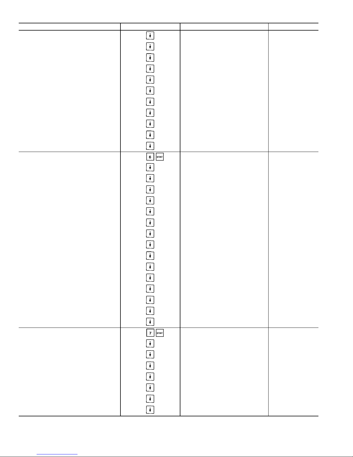
Table 10 — Status Function and Subfunction Directory (cont)
SUBFUNCTION KEYPAD ENTRY DISPLAY COMMENT
5 Circut B Analog Valves (cont)
B1 Motor Temperature
xxx.x dF
B2 Motor Temperature
xxx.x dF
SAT Condensing Temp
xxx.x dF
Saturated Suction Temp
xxx.x dF
EXV Percent Open
xxx.x%
Motormaster Speed
xxx.x%
Water Valve Position
xxx.x%
Cooler Level Indicator
x.xx
CPM B1 Feedback
x.x Volts
See Table 3.
CPM B2 Feedback
x.x Volts
See Table 3.
Circuit B Econ Pressure
xxx.x PSI
6 Circuit B Discrete Inputs/Outputs
CIR. B DISCRETE OUTPUTS
Compressor B1
Off/On
Compressor B2
Off/On
Loader B1
Off/On
Loader B2
Off/On
Minimum Load Valve B
Off/On
Circuit B Oil Heater
Off/On
B1 Mtr Cooling Solenoid
Off/On
B2 Mtr Cooling Solenoid
Off/On
Circuit B Oil Pump
Off/On
Oil Solenoid B1
Off/On
Oil Solenoid B2
Off/On
CIR. B DISCRETE INPUTS
Circuit B Oil Switch
Open/Close
Compressor B1 Feedback
Off/On
Compressor B2 Feedback
Off/On
7 Unit Analog Parameters
UNIT ANALOG PARAMETERS
Cooler Entering Fluid
xx.x dF
Cooler Leaving Fluid
xx.x dF
Condenser Entering Fluid
xx.x dF
Condenser Leaving Fluid
xx.x dF
Reclaim Entering Fluid
xx.x dF
Reclaim Leaving Fluid
xx.x dF
5 Volt Supply
x.x Volts
See Legend on page 23.
20
Page 21
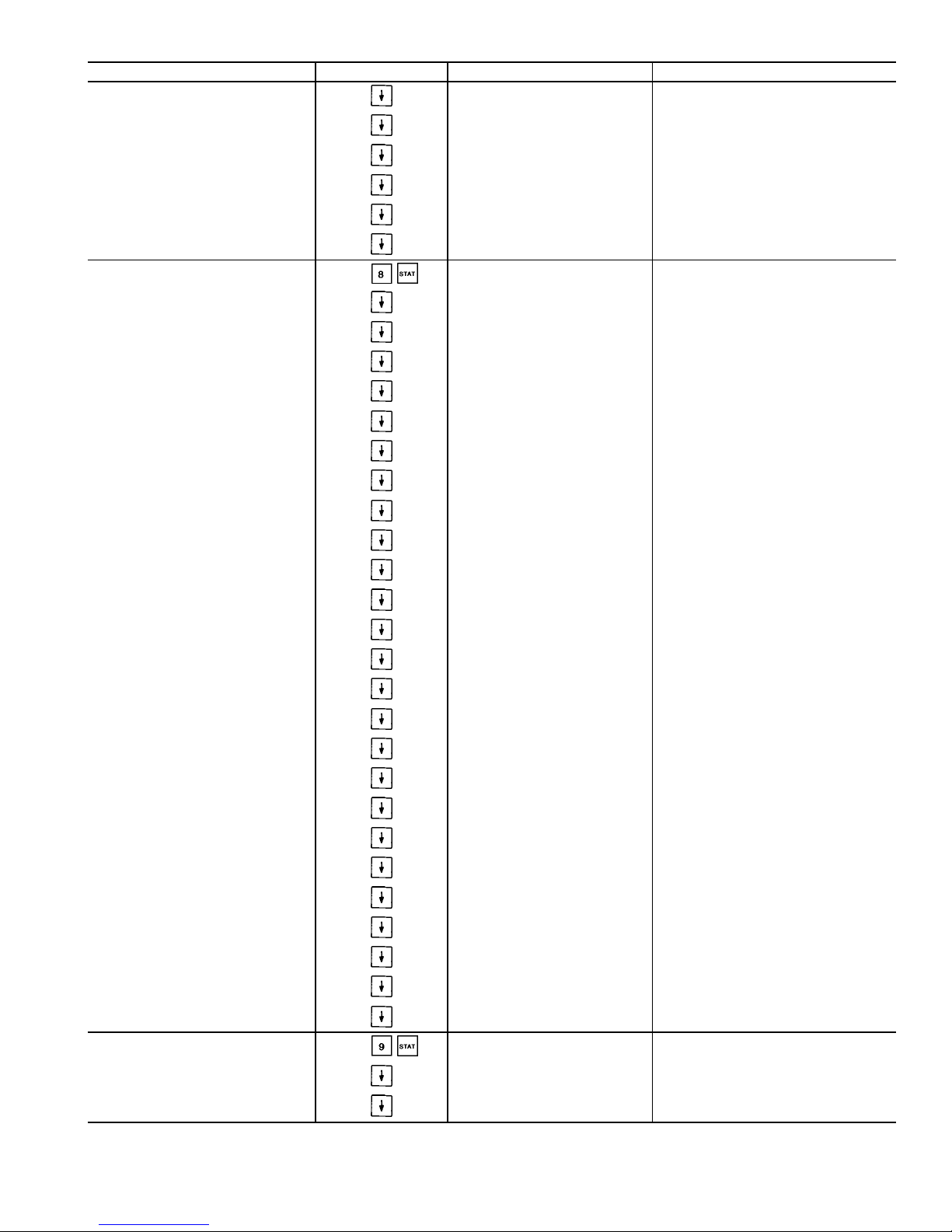
Table 10 — Status Function and Subfunction Directory (cont)
SUBFUNCTION KEYPAD ENTRY DISPLAY COMMENT
7 Unit Analog Parameters (cont)
TEMPERATURE RESET
4-20 mA Reset Signal
xx.x mA
Return Reset Signal
xx.x dF
External Reset Signal
xx.x dF
Outdoor Air Temp
xx.x dF
Calculated Reset
xx.x dF
8 Misc. Inputs/Outputs
MISC INPUTS/OUTPUTS
FAN_1
Off/On
FAN_2
Off/On
FAN_3
Off/On
FAN_4
Off/On
FAN_5
Off/On
FAN_6
Off/On
DEMAND LIMIT
4-20 mA Demand Signal
xx.x mA
Demand Switch 1
Off/On
Demand Switch 2
Off/On
CCN Loadshed Signal
Normal/Alarm
Max Allowable CAP
xxx.x%
PUMPS
Cooler Pump Relay
Off/On
Cooler Pump Flow Switch
Off/On
Condenser Pump Relay
Off/On
Condenser Pump Flow Switch
Off/On
MISCELLANEOUS
Ice Valve
Off/On
Ice Build Complete
Yes/No
Heat/Cool Switch
Heat/Cool
Dual Set point Switch
Off/On
Cooler Heater
Off/On
Options Temperature 1
xx.x dF
Not Used
Options Temperature 2
xx.x dF
Not Used
9 Operating Modes
MODES :MODE_TBL
mode name ON/OFF
Only active modes displayed
LOCAL OFF Scroll with down arrow key to display
CCN OFF
21
Page 22
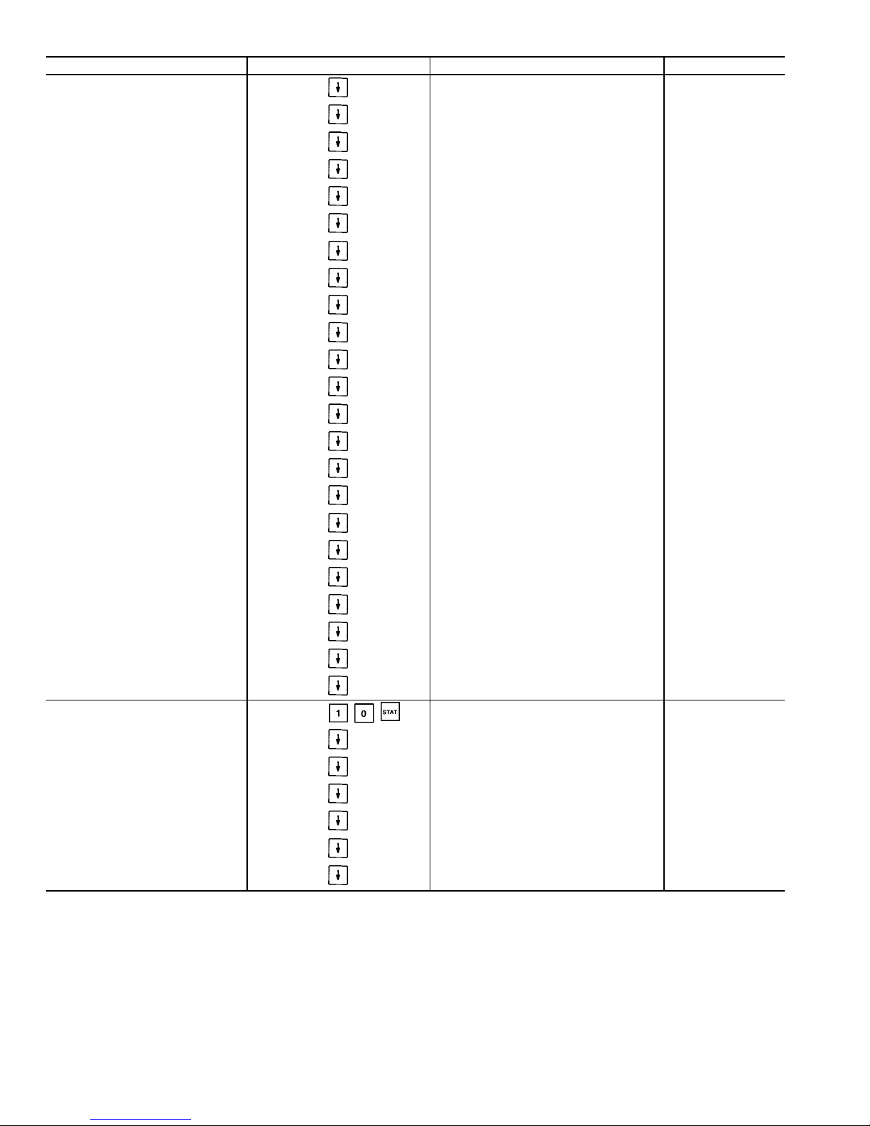
Table 10 — Status Function and Subfunction Directory (cont)
SUBFUNCTION KEYPAD ENTRY DISPLAY COMMENT
9 Operating Modes (cont)
CLOCK OFF
LOCAL ON
CCN ON
CLOCK ON
DUAL SP ACTIVE (1st SP)
DUAL SP ACTIVE (2nd SP)
TEMPERATURE RESET
ACTIVE
DEMAND LIMIT ACTIVE
LOAD LIMIT ACTIVE
LOW SOURCE TEMP PROTECT
RAMP LOADING ACTIVE
TIMED OVERRIDE ACTIVE
LOW COOLER SUCTION TEMP
WSM CONTROLLING
SLOW CHANGE OVERRIDE
OFF TO ON DELAYACTIVE
FSM CONTROLLING
2 CHILLR LEAD LAG ACTIVE
2 CHILLR LL COMM FAILURE
CIR A LOW DISCHG SUPERHT
CIR B LOW DISCHG SUPERHT
CIR A HIGH SDT
CIR B HIGH SDT
10 Capacity Control
CAPACITY CONTROL
Load/Unload Factor
xxx.x%
Control Point
xx.x dF
Leaving Water Temp
xx.x dF
MISC. INDICATORS
Liquid Lvl Sensor Cir. A
xx.x dF
Liquid Lvl Sensor Cir. B
xx.x dF
22
Page 23
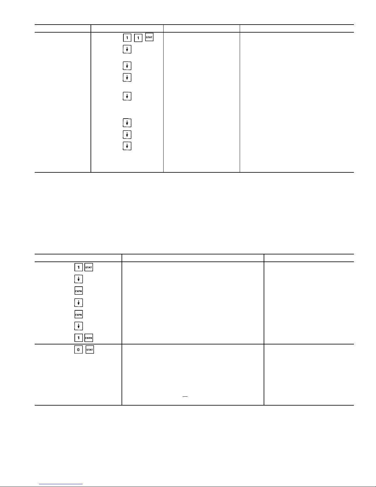
Table 10 — Status Function and Subfunction Directory (cont)
SUBFUNCTION KEYPAD ENTRY DISPLAY COMMENT
11 Dual Chiller
DUAL CHILLER
Unit Master / Slave
0/1/2
0 = Neither
1 = Slave
2 = Slave
Master / Slave Ctrl Active
Yes/No
Lead Chiller
1/2
1 = Master
2 = Slave
Slave Chiller State
0/1/3/5/6
0 = Chiller OFF
1 = Valid Run State in CCN Mode
3 = Chiller in Local Mode
5 = Shutdown on Alarm
6 = Communications Failure
Slave Chiller Total Cap
xxx.x%
Lead / Lag Changeover Yes if Lead / Lag Balance Enabled
Master / Slave Error
1/2/3/4/5/6
1 = Master / Slave Have Same Address
2 = Master / Slave Communication Failure
3 = Chiller in Local Mode
4 = Slave Shutdown on Alarm(s)
5 = Master Configured for Heating
6 = No Slave Configured
LEGEND
CCN — Carrier Comfort Network
CPM — Compressor Protection Module
dF — Degrees Fahrenheit
EXV — Electronic Expansion Valve
FSM — Flotronic™ System Manager
LL — Lead/Lag
SAT — Saturated
SDT — Saturated Discharge Temperature
SP — Set Point
WSM — Water System Manager
Table 11 — Reading and Clearing Alarms
KEYPAD ENTRY DISPLAY COMMENT
Alarm: 02
Reset Alarms: 1 <ENTER>
Comp A1 Fail - 1.70 Volt
Alarm : 15:12 04/15/96
Comp A1 Fail - 1.70 Volts Phase Reversal
Alarm : 15:12 04/15/96
Compressor A1 Low Oil Pr
Alarm : 10:34 04/15/96
Compressor A1 Low Oil Pressure
Alarm : 10:34 04/15/96
Alarm: 02
Reset Alarms: 1 <ENTER>
Press Reset
button first
Alarm: 00
Reset Alarms: 1 <ENTER>
Alarms reset
and cleared
Entering Fluid Temp
xx.x dF
Returns to rotating
default display
Leaving Fluid Temp
xx.x dF
Percent Total Capacity
xxx.x%
Total Number of Alarms
xx
MODES: MODE
TBL
List of All Current Modes
23
Page 24
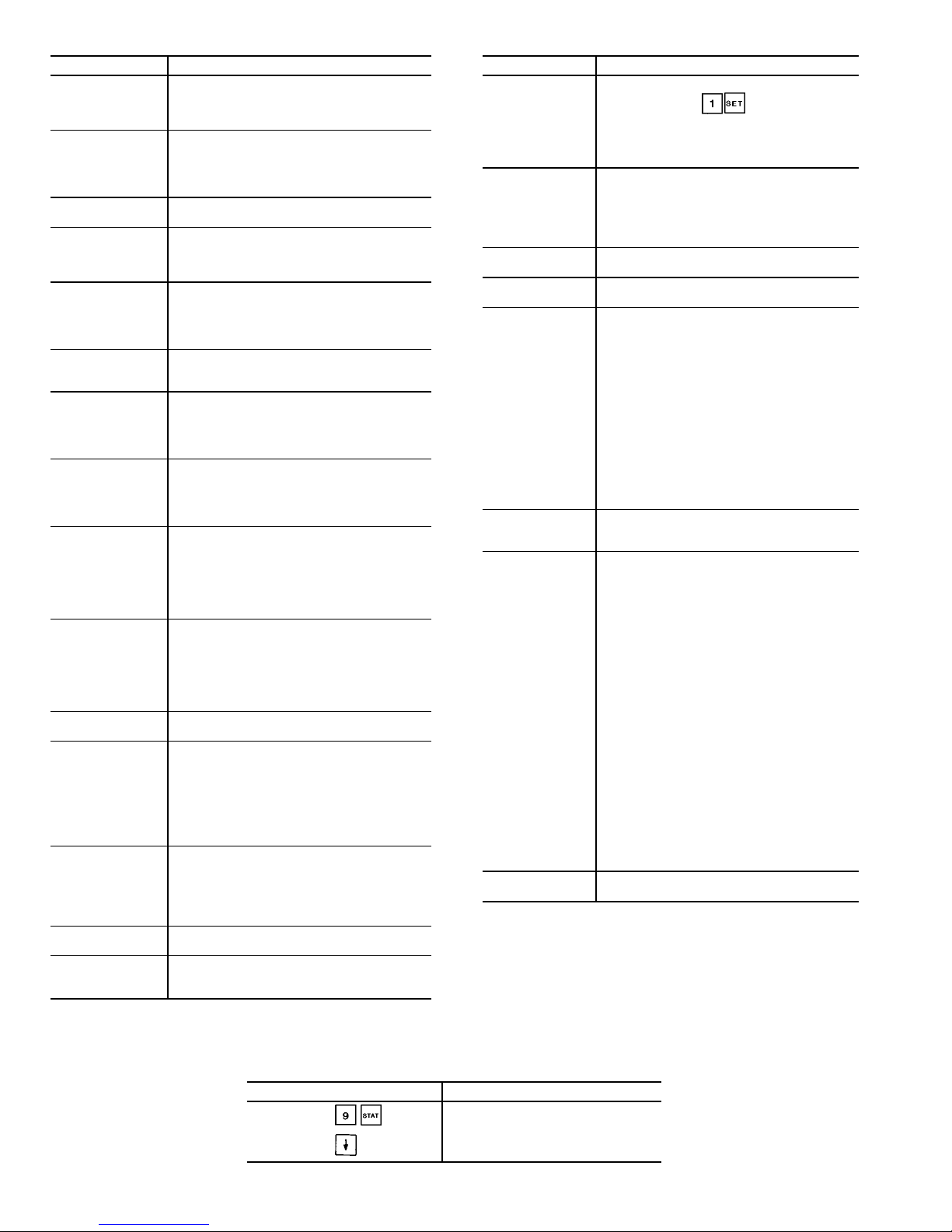
Table 12 — Operational and Mode Display Codes
CODE DESCRIPTION
LOCAL OFF Unit is off. LOCAL/OFF/REMOTE switch is
in OFF position or LOCAL/OFF/REMOTE
switch is in REMOTE position and remote
contacts are open.
CCN OFF Unit is off. LOCAL/OFF/REMOTE switch is
in LOCAL position and CCN control is
enabled (Stop state) or CCN is enabled
(Stop state) with LOR switch in REMOTE
position and remote contacts closed.
CLOCK OFF Unit is off due to internal clock schedule.
LOR switch is in LOCAL position.
LOCAL ON Unit is on. LOR switch is in LOCAL position
and CCN is disabled or LOR switch is in
REMOTE position with contacts closed and
CCN is disabled.
CCN ON Unit is on due to CCN command. LOR
switch is in LOCAL position and CCN is
enabled (Run state) or LOR switch is in
REMOTE position with contacts closed and
CCN is enabled (Run state)
CLOCK ON Unit is on due to internal clock schedule or
occupied override function. LOR switch is
in LOCAL position.
DUAL SP ACTIVE
(1st SP)
Dual set point is in effect. In this mode, unit
continues to run in an occupied condition,
and leaving fluid set point is automatically
controlled to the CSP1 set point in the SET
POINT function.
DUAL SP ACTIVE
(2nd SP)
Dual set point is in effect. In this mode, unit
continues to run in unoccupied condition,
but leaving fluid set point is automatically
increased to a higher level (CSP2 set point
is in SET POINT function).
TEMPERATURE
RESET ACTIVE
Temperature reset is in effect. In this mode,
unit is using temperature reset to adjust
leaving fluid set point upward, and unit is
currently controlling to the modified set
point. The set point can be modified based
on return fluid, outdoor-air temperature,
space temperature, or 4 to 20 mA signal.*
DEMAND LIMIT
ACTIVE
Demand limit is in effect. This indicates that
capacity of unit is being limited by demand
limit control option. Because of this
limitation, the unit may not be able to
produce the desired leaving fluid
temperature. Demand limit can be controlled
by a switch or 4 to 20 mA signal.*
FSM
CONTROLLING
Flotronic™ System Manager (FSM) is
controlling the chiller.
RAMP LOADING
ACTIVE
Ramp load (pulldown) limiting is in effect.
In this mode, the rate at which leaving fluid
temperature is dropped is limited to a
predetermined value to prevent compressor
overloading. See CRAMP set point in the
SET function in (page 25). The pulldown limit
can be modified, if desired, to any rate from
0.2° F to 2° F (0.1° to 1° C)/minute.
TIMED OVERRIDE
ACTIVE
Timed override is in effect. This isa1to
4 hour temporary override of the programmed schedule, forcing unit to occupied
mode. Override can be implemented with
unit under LOCAL/REMOTE or CCN control.
Override expires after each use.
WSM
CONTROLLING
Water System Manager is controlling the
chiller.
SLOW CHANGE
OVERRIDE
Slow change override is in effect. The
leaving fluid temperature is close to and
moving towards the control point.
CODE DESCRIPTION
OFF TO ON
DELAY ACTIVE
Chiller is being held off by Minutes Off Time
found by keying . Also, normal
operation of the chiller includes a minimum
1.5 minute delay after a capacity stage
change has been made. This delay is
adjustable from 1.5 to 6 minutes.
LOAD LIMIT
ACTIVE
This function determines the maximum
allowable capacity that can be running and
is accomplished through the Flotronic
System Manager. The unit may not be able
to produce the desired leaving fluid
temperature.
2 CHILLR LEAD
LAG ACTIVE
Future Use.
2 CHILLR LL
COMM FAILURE
Future Use.
CIRCUIT A LOW
DISCHARGE
SUPERHT
If the circuit discharge superheat is less
than 15° F (8.3° C), the capacity control
routine will not add any stages (to either
circuit).
If the compressor has been running for at
least 3 minutes, the EXV will not be
opened any further. If the circuit
discharge superheat is less than 10° F
(5.6° C) and falling, the circuit EXV will
be closed 50 steps every 10 seconds.
If the discharge superheat is less than
5° F (2.8° C) and falling, a circuit loader
will be deenergized every 30 seconds.
The final stage will not be unloaded
unless an alarm condition is present.
CIRCUIT B LOW
DISCHARGE
SUPERHT
See description for Circuit A above.
CIRCUIT A
HIGH SCT
If the circuit is running and the Saturated
Condensing Temperature (SCT) is greater
than the Maximum Condensing
Temperature Set point (MCT_SP) minus
12° F (6.7° C), the control will not add
any stages.
If the SCT is greater than the MCT_SP
plus 5° F (2.8° C), the circuit will be
unloaded and shut down if necessary. If
the SCT is greater than the MCT_SP plus
2° F (1.1° C) for one minute, a loader will
be deenergized.
If the SCT is greater than the MCT_SP
minus 4° F (2.2° C), the control will
compare the maximum operating
pressure set point (MOP_SP) with the
modified MOP_SP (MOP_CTRL).
If the MOP_CTRL is greater than the
MOP_SP, the mode will be cleared.
Otherwise the control will display the
high SCT override mode. The capacity
control routine will not add any stages. If
the circuit is at its lowest capacity, this
mode will be ignored.
CIRCUIT B
HIGH SCT
See description for Circuit A above.
LEGEND
CCN — Carrier Comfort Network
CSP — Cooling Set Point
CRAMP — Cooling Ramp Loading
EXV — Electronic Expansion Valve
LOR — Local/Off/Remote
SP — Set Point
WSM — Water System Manager
*Afield-supplied500Ohm
1
⁄2W resistor must be installed across the
input terminals when usinga4to20mAsignal.
Table 13 — Reading Current Operating Modes
KEYPAD ENTRY DISPLAY
MODES :MODE_TBL
CCN ON
DEMAND LIMIT
ACTIVE
24
Page 25

TEST FUNCTION — The test function operates the diagnostic program. To initiate the test function, the LOCAL/
OFF/REMOTE switch must be in the OFF position.
To reach a particular test, press its subfunction number
followed by the key then scroll to the desired test by
pressing the down arrow key. Refer to Table 14 for a com-
plete description of the test function.
To start a test of discrete outputs, press . To end
the test, simply press the key or press . Pressing
the key after a test has started advances the system to
the next test, whether the current test is operating or has timed
out. Circuit A discrete outputs can be tested in and
include loaders, minimum load valve, oil heater (if equipped),
motor cooling solenoids, oil pump, and oil solenoids. Similarly, Circuit B discrete outputs can be tested in
.Additionaldiscrete outputs, including condenser fans,
cooler heater, water pumps, and remote alarms can be tested
in .
Press to access Valves and Motormastert device
analog outputs. Scroll down to display Circuit A EXV Valve
with a target percent of 0%. Press to step the EXV
to 25%. Pressing three additional times will move
the EXV to 50%, 75%, and 100%. The EXV may be closed
in 25% steps by pressing for each desired step. Wait
30 seconds between each step when opening and closing for
the valve to stop moving. Pressing the down arrow will display Circuit B EXV Valve and it is tested in the same manner as Circuit A. Also available for test are Circuit A water
valve (if equipped) and the Circuit A and B Fan speed %
(direct control Motormaster device) outputs for 30GX chillers. These are tested in the same manner as the EXV valves.
Note that condenser fan motors are NOT started during fan
speed quick tests. Measure 4 to 20 mA dc output using meter
in series with violet wire to controller. See page 72 of Field
Wiring section.
While the unit is in test, you can leave the test function
and access another display or function by pressing the appropriate keys. However,a component that is operating when
another function is accessed remains operating. You must
re-enter the test function and press to shut down the
component. Components with a timed operating limit time
out normally even if another function is accessed.
Since the Test function checks only certain outputs, it is
a good practice to also check all inputs and outputs accessible through the status function. These can be located by
pressing through . If keypad is not used for
10 minutes, the unit automatically leaves the test function
and resumes the normal rotating display. See Table 15.
HISTORY FUNCTION — Pressing displays total
machine operating hours. Scroll down to display machine
run time and starts, and total run time and starts for each
compressor. Refer to Table 16 for a complete description of
the function. When the PSIO-1 module is replaced or downloaded with Version 4.0 or later software, the number of starts
and run hours may be changed one time. Record the current
values from the PSIO before removing the module or downloading new software. The number of starts and hours may
be changed by entering the desired value at the HSIO and
pressing the key.
Pressing displays the last 10 alarms along with a
description and time and date of occurrence of each alarm.
SET POINT FUNCTION — Set points are entered through
the keypad. Set points can be changed within the upper and
lower limits, which are fixed. The ranges are listed below.
Refer to Table 17 for a complete description of the function.
Cooling Set Point 1,2
Water:
Medium
Temperature Brine:
Low
Temperature Brine:
38 to 70 F
(3.3 to 21.1 C)
14 to 70 F
(−10 to 21.1 C)
−13 to 70 F
(−25 to 21.1 C)
Reset Set Points
Maximum
Reset Range:
−30 to 30 F
(−17 to 17 C)
External Temperature
Reset:
−40 to 240 F
(−40 to 118 C)
Chiller Fluid D:
0° to 15 F
(0° to 8 C)
External Signal Reset: 4 to 20 mA (2-10 vdc with
500 Ohm resistor)
Demand Limit Set Points
Switch Input: Step1—0to100% Capacity Reduction
Step2—0to100% Capacity Reduction
External Signal: Maximum Demand Limit 4 to 20 mA
(2-10 vdc with 500 Ohm resistor)
Minimum Demand Limit 4 to 20 mA
(2-10 vdc with 500 Ohm resistor)
Loadshed Demand Delta: 0 to 60%
Maximum Loadshed Time: 0 to 120 min.
Head Pressure Set Points
Air cooled chillers (30GX): 80 to 135 F (26.7 to 57.2 C)
Water cooled chillers (30HX): 80 to 128 F (26.7 to 53.3 C)
Set Point Table — The unit operating set points can be found
under . Use the down arrow key to scroll through
the set points. The first set point is Cool Set Point 1. This is
the occupied chilled fluid set point. Scroll down to Cool Set
Point 2 and then to the Cooling Ramp load multiplier which
is configurable from 0.2 to 2.0° F/min. (0.11 to 1.1° C/min.).
This value is the maximum rate at which the leaving fluid
temperature is allowed to drop without adding a stage. Cooling Set Point 2 is used in conjunction with the dual set point
switch function. This is used as the low temperature set point
for ice duty or as the unoccupied set point. Press the down
arrow key to display the Circuit A and B head pressure set
points. The remaining set points in this subfunction include
demand limit, LCW (leaving chilled water) delta alarm limit,
minutes off time, and motor temperature set point.
Display Units — Press to display the units of measure being used. Type 0 is for English and type 1 is for
Metric.
Address — For CCN configurations, press and
scroll down to display the address and bus number of the
chiller.
Time — Press and scroll down to read and change
the unit day of week, time, day of month, month of year and
year of century. See the examples in Table 17 for making
changes to these values.
CCN Enable/Disable — Press to disable the CCN
control of the chiller. This function will override CCN con-
trol commands. The CCN Enable value under must
be ON to activate this function. With CCN Enable set to ON
and Disable CCN Control set to ‘‘0,’’ the chiller will function normally under CCN control. With Disable CCN Control set to ‘‘1,’’ the chiller will operate in a local mode under
its own control.
Reading and Changing Set Points — Table 18 shows how
to read and change the chilled fluid set point. Other set points
can be changed by following the same procedure. Refer to
Table 17 for the sequence of display of set points in each
subfunction.
25
Page 26

Table 14 —Test Function and Subfunction Directory
SUBFUNCTION KEYPAD ENTRY DISPLAY COMMENT
1 Circuit A Discrete Output
Circuit A Discrete Output
Loader A1
Relay is OFF
Loader A1
Relay is ON
Loader A2 Similarly, use to test remaining outputs. Press the
down arrow key or to turn an output off.
Minimum Load Valve A
Circuit A Oil Heater
A1 Mtr. Cooling Solenoid
A2 Mtr. Cooling Solenoid
Circuit A Oil Pump
Oil Solenoid A1
Oil Solenoid A2
NOTE: Output will display Relay is ABSENT when
not configured
2 Circuit B Discrete Outputs
Circuit B Discrete Outputs
Loader B1
Relay is OFF
Loader B1
Relay is ON
Loader B2 Similarly, use to test remaining outputs. Press the
down arrow key or to turn the output off.
Minimum Load Valve B
Circuit B Oil Heater
B1 Mtr. Cooling Solenoid
B2 Mtr. Cooling Solenoid
Circuit B Oil Pump
Oil Solenoid B1
Oil Solenoid B2
NOTE: Output will display Relay is ABSENT when
not configured
3 Unit Discrete Output
Unit Discrete Output
Fan 1
Relay is OFF
Fan 1
Relay is ON
Fan 2 Similarly use to test remaining outputs. Press the
down arrow key or to turn output off.
Fan 3
Fan 4
Fan 5 Energizes Circuit A fans for 30HXA units.
Fan 6 Energizes Circuit B fans for 30HXA units.
Cooler Pump
Condenser Pump
Cooler Heater
Alarm
Remote Alarm 1 Currently not supported.
26
Page 27

Table 14 —Test Function and Subfunction Directory (cont)
SUBFUNCTION KEYPAD ENTRY DISPLAY COMMENT
3 Unit Discrete Output (cont)
Remote Alarm 2 Currently not supported.
Remote Alarm 3 Currently not supported.
Remote Alarm 4 Currently not supported.
Remote Alarm 5 Currently not supported.
Remote Alarm 6 Currently not supported.
Remote Alarm 7 Currently not supported.
Remote Alarm 8 Currently not supported.
Remote Alarm 9 Currently not supported.
Remote Alarm 10 Currently not supported.
Remote Alarm 11 Currently not supported.
Remote Alarm 12 Currently not supported.
Remote Alarm 13 Currently not supported.
Remote Alarm 14 Currently not supported.
Remote Alarm 15 Currently not supported.
Remote Alarm 16 Currently not supported.
4 Valves and Motormaster
Valves and Motor Master
Circuit A EXV Valve
Target Percent = 0%
Circuit A EXV Valve
Target Percent = 25%
Step in 25% increments.
Circuit A EXV Valve
Target Percent = 50%
Wait 30 seconds between each step for valve to stop moving.
Circuit A EXV Valve
Target Percent = 75%
Valve may be closed in 25% increments by keying in .
Wait 30 seconds between each step for valve to stop moving.
Circuit A EXV Valve
Target Percent = 100%
Circuit B EXV Valve
Target Percent = 0%
Test same method as for Circuit A
Circuit A Water Valve
Target Percent = 0%
Test same method as for EXV valves
Circuit A% Fan Speed Test same method as for EXV valves
Circuit B% Fan Speed Test same method as for EXV valves
LEGEND
EXV — Electronic Expansion Valve
Table 15 — Using Test Function
KEYPAD ENTRY DISPLAY RESPONSE COMMENTS
Circuit A Discrete Output
Loader A1
Relay is OFF
Appears on screen momentarily, then will switch to Loader A1.
Loader A1
Relay is ON
Compressor Loader A1 solenoid energized
Loader A1
Relay is OFF
Compressor Loader A1 solenoid deenergized
Valves and Motor Master
Circuit A EXV Valve
Target Percent = 0%
Circuit A EXV Valve
Target Percent = 25%
Continue pressing to step to 50%, 75%, and 100%.
Circuit A EXV Valve
Target Percent = 0
Continue pressing to step closed.
LEGEND
EXV — Electronic Expansion Valve
27
Page 28
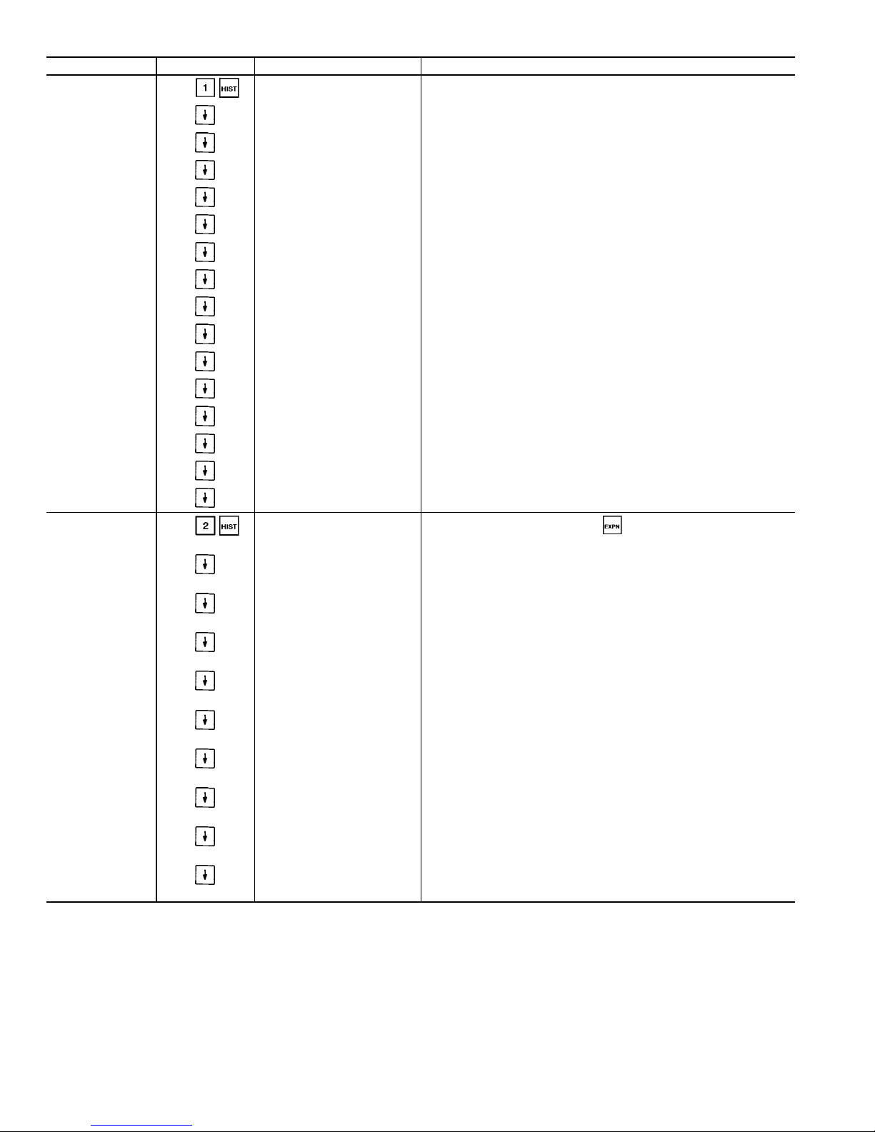
Table 16 — History Function and Subfunction Directory
SUBFUNCTION KEYPAD ENTRY DISPLAY COMMENT
1 Operating Hours
Machine Operating Hours
xxx.x hours
Number of hours unit has at least
1 compressor running
Number of unit starts from
zero capacity
These values may be changed once, when new software is downloaded or when the PSIO-1 module is replaced (Version 4.0 and later).
Machine Starts
xxx
Circuit A
Operating Hours
xxx.x hours
Compressor A1 Hours
xxx.x hours
Compressor A2 Hours
xxx.x hours
Starts
Compressor A1 Starts
xxx
Compressor A2 Starts
xxx
Circuit B
Operating Hours
xxx.x hours
Compressor B1 Hours
xxx.x hours
Compressor B2 Hours
xxx.x hours
Starts
Compressor B1 Starts
xxx
Compressor B2 Starts
xxx
2 Alarm History
Previous Alarm 1 - description
Alarm description, time/day
of occurrence
Lists 10 most recent alarms. Use key when necessary
Previous Alarm 2 - description
Alarm description, time/day
of occurrence
Previous Alarm 3 - description
Alarm description, time/day
of occurrence
Previous Alarm 4 - description
Alarm description, time/day
of occurrence
Previous Alarm 5 - description
Alarm description, time/day
of occurrence
Previous Alarm 6 - description
Alarm description, time/day
of occurrence
Previous Alarm 7 - description
Alarm description, time/day
of occurrence
Previous Alarm 8 - description
Alarm description, time/day
of occurrence
Previous Alarm 9 - description
Alarm description, time/day
of occurrence
Previous Alarm 10- description
Alarm description, time/day
of occurrence
28
Page 29
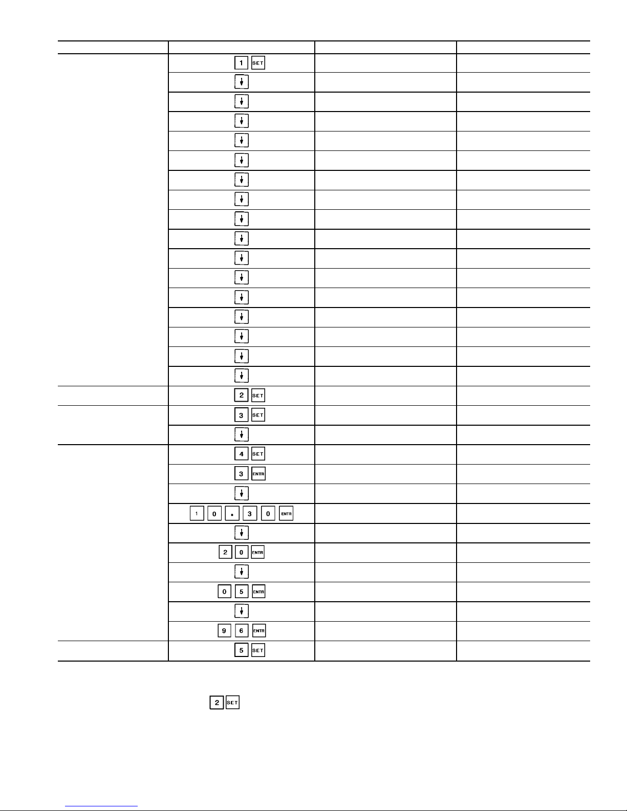
Table 17 — Set Point Function and Subfunction Directory
SUBFUNCTION KEYPAD ENTRY DISPLAY COMMENT
1 Set Point Table
COOLING
Cool Setpoint 1
xx.x dF
Default: 44.0
Cool Setpoint 2
xx.x dF
Default: 44.0
Cooling Ramp Loading
xx.x dF
Default: 0.5
HEATING NOT SUPPORTED
Heat Setpoint 1
xx.x dF
NOT SUPPORTED
Default: 98.0
Heat Setpoint 2
xx.x dF
NOT SUPPORTED
Default: 98.0
Heating Ramp Loading
xx.x dF
NOT SUPPORTED
Default: 0.5
HEAD PRESSURE
Head Pressure Setpoint A
xxx.x dF
Default: 113.0 (GX)
100.0 (HXA) 85.0 (HXC)
Head Pressure Setpoint B
xxx.x dF
Default: 113.0 (GX)
100.0 (HXA) 85.0 (HXC)
DEMAND LIMIT
Demand Switch 1 Setpoint
xxx.x%
Default: 80.0%
Demand Switch 2 Setpoint
xxx.x%
Default: 50.0%
LCW Delta Alarm Limit
xxx.x dF
Default: 50.0 dF
Minutes Off Time
xxx min
Default: 0 min
Motor Temp Set Point
xxx.x dF
Default: 200.0 dF
2 Units
US IMPERIAL/METRIC
0
0 = English (Default)
1 = Metric
3 Address
TARGETADDRESS
x
Default: 1
TARGET BUS NUMBER
x
Default: 0
4 Time
Day of Week
Monday
Mon=1, Tues=2, etc.
Day of Week
Wednsday
Day of week set
TIME (HOUR:MIN)
00:00
Enter military format
TIME (HOUR:MIN)
10:30
Time of day set
DAY OF MONTH
xx
DAY OF MONTH
20
Day of month set
MONTH OF YEAR
xx
MONTH OF YEAR
05
Month of year set
YEAR OF CENTURY
xx
YEAR OF CENTURY
96
Year of century set
5 CCN Disable
Disable CCN Control
x
0=no, 1=yes
Default: 0
LEGEND
CCN — Carrier Comfort Network
LCW — Leaving Chilled Water
NOTE: If metric option is selected under , temperatures are expressed
in degrees Celsius and pressures are expressed in kPa.
29
Page 30
Table 18 — Reading and Changing
Chilled Fluid Set Point
KEYPAD ENTRY DISPLAY RESPONSE COMMENTS
COOLING Change set point from
default to 48 F.
Cool Set point 1
44.0 F default
Cool Set point 1
48.0 F
Set point change
complete
SERVICE FUNCTION — This function allows the technician to view and input configuration data. Factory configuration data, field configuration data, and service configuration data may be viewed or entered through the keypad and
display module. See Table 19 for a complete listing of configurable items. Whenever a processor module is replaced in
the field, the complete list of configuration codes should be
checked for correct settings. The current software version
can be displayed. See Table 20.
Scroll down in this function to display configuration information including number of compressors, tonnage, and
compressor must-trip amps.
Password Protection of HSIO Configurable Service Points
— To modify configurations and values and to use the manual
control subfunction, the password must be entered before the
first change can be made. The default password is set to
. See Table 21 for an example of how to
enter the password to change the Lead/Lag configuration.
Options Configuration Tables 1 and 2 — These subfunc-
tions can be accessed by pressing or and scrolling down to display the configuration options. See Table 19
for a complete list of these options.
Temperature Reset, Demand Limit and Head Pressure PID
Configurations —Press andscrolldowntoview the
configuration information. See Table 19 for a complete list.
Factory Configuration Codes — Pressing allows
entry into the factory and service configuration codes
subfunction. Under this subfunction, there are 5 configuration codes that are downloaded at the factory. Each code is
made up of 8 digits. If the processor module is replaced in
the field, these 5 configuration codes should be checked using the keypad and HSIO display module. See Table 22 for
a descriptionofthefactory configuration codes (codes 1 through
3) and service configuration codes (codes 4 and 5).
The factory and service configuration codes are found by
pressing . These are preset from the factory.They can
be verified by following the description in Table 22. These
codes MUST be checked and corrected in the field if the
PSIO-1 module is replaced.
NOTE: The LOCAL/OFF/REMOTE switch must be in the
OFF position to change configuration codes.
A label is applied to a control box panel with a list of
factory and service codes for particular units. Table23shows
how to configure a new PSIO-1 module for use in a 30HXC106---501CA water cooled chiller.
Transducer Calibration — Press and scroll down to
view the transducer calibration information. See Table 19
for a complete list, and the Pressure Transducers section on
page 59 for a description of this subfunction.
Manual Control Mode — This control allows the user to
have full control over the compressors, loaders, and the minimum load valve (if installed) of the machine. Normal safeties such as high pressure, oil level and pressure, and CPM
related alarms are NOT bypassed in this control mode. The
capacity control function and overrides ARE bypassed when
using the manual control mode. To enter this mode, switch
the LOR switch to OFF. Press at the HSIO. The display will read Manual Control Enable - Disable. Press
and switch the LOR switch to Local. The display will change
to Manual Control Enable - Enable. The Disable and Enable
will appear on the second line of the display. See Table 19
for a complete list of this function.
Scroll down and press to start the desired com-
pressor.The control will start the compressor if the pre-lube
cycle is passed, just as in normal operation. Press to
add loaders as desired and press to turn off loaders
and compressors. The Minimum Load Valve can be energized using the same procedure.
Dual Chiller Configuration — Press to enter the Dual
Chiller control configuration. This method of control is for
a stand-alone Master/Slave combination of chillers and will
NOT work with the Flotronic™ System Manager (FSM).
The Minus One Pass Cooler option is required for this
configuration.
The chillers should be piped for series flow through the
coolers. The Master chiller must be downstream from the
Slave chiller leaving water.BoththeMasterand Slave chiller
must be connected to the same CCN Level II communications bus with different addresses. To enable the dual chiller
configuration the CCN Enable function must be set
to Enable for each chiller, otherwise each chiller will oper-
ate independently. This value can be activated through the
HSIO or through a CCN device. Both chillers should be con-
figured for Close Control and require flow switches
to be installed. For cooler pump control, wire both Master
and Slave chiller outputs to the cooler pump starter.All system inputs (temperature reset, demand limit, dual set point,
etc.) should be connected to the Master chiller. If Lead/Lag
Balance is disabled, the Master chiller will always be the
lead chiller. If Lead/Lag Balance is enabled, the control will
alternate between the Master and Slave chillers to keep their
respective run hours balanced within the value configured
for Lead/Lag Balance Delta. The desired leaving fluid set
point for the Duplex chiller must be configured in
the Master chiller. CCN Control of the chillers can be dis-
abled locally through the HSIO by entering and enabling the Disable CCN Control value. This value must be
disabled before the chiller will return to Duplex control.
30
Page 31
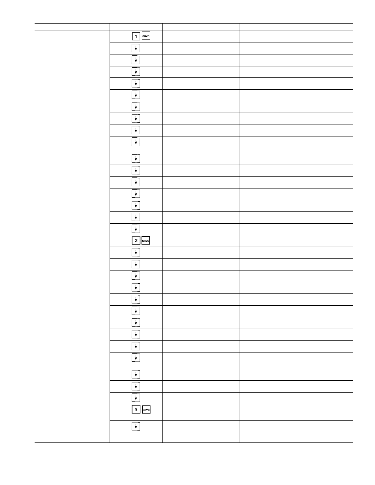
Table 19 — Service Function and Subfunction Directory
SUBFUNCTION KEYPAD ENTRY DISPLAY COMMENT
1 Service Configuration
Software CESR_500100 Ver
xxx
Unit Type
x
1 = Air-cooled,2=Water-cooled
3 = Split system
Number of Cir A Comp
x
Compressor A1 Tonnage
xx
Compressor A2 Tonnage
xx
Oil Switch Configuration
x
Number of Cir B Comp
x
Compressor B1 Tonnage
xx
Compressor B2 Tonnage
xx
Max. Cond. Temp Setpoint
xxx.x dF
30GX = 154 F (68 C)
30HXA = 152 F (67 C)
30HXC = 122 F (50 C)
MOP Set point
xx.x dF
Default = 52 F (11.1 C)
Fan Staging Select
x
Displays ‘‘Not Used’’ or a
number. See Table 5
CPM Board Used?
Yes
Compr. A1 Must Trip Amps
xxx.x
Value from CPM module. See Appendix A.
Compr. A2 Must Trip Amps
xxx.x
Value from CPM module. See Appendix A.
Compr. B1 Must Trip Amps
xxx.x
Value from CPM module. See Appendix A.
Compr. B2 Must Trip Amps
xxx.x
CURRENTLY NOT USED
2 Options Configuration 1
Cooler Fluid Select
x
1 = Water (Default), 2 = Medium Temp Brine
3 = Low Temp Brine (HX only)
Min. Load Valve Select
x
Displays Enable/Dsable
Default: Dsable
Loading Sequence Select
x
1 = Equal circuit, 2 = Staged circuit
Default: 2. See page 6
Lead/Lag Sequence Select
x
1 = Automatic (Default), 2 = Circuit A leads,
3 = Circuit B leads
Head Press. Control Type
x
0 = None (Default, HX), 1 = Air cooled
(Default, GX),2=Water cooled
Motormaster Select
x
0 = None (Default), 1 = Direct control
Water Valve Type
x
0 = None (Default), 1 = 4-20 mA, 2 = 0-10 V,
3 = 20-4 mA, 4 = 10-0 V
Ext. Reset Sensor Select
x
0 = Space Temp Thermistor (Default)
1 = Outside Air Thermistor
Cooler Pump Interlock
x
0 = No interlock
1 = Interlock enabled (Default)
Cooler Pump Control
x
0 = Not controlled (Default)
1 = On/Off Control
Condenser Pump Control
x
0 = Not controlled (Default)
1 = On/Off Control
2 = Off when stages equal 0 (unit off)
Condenser Flow Switch
x
Displays Enable/Dsable
Default: Dsable
Condenser Water Sensors
x
0 = Not used (Default), 1 = Used
Heat Reclaim Sensors
x
CURRENTLY NOT SUPPORTED
3 Options Configuration 2
Cooling Setpoint Select
x
0 = Single set point (Default), 1 = Dual
set point (switch controlled), 2 = Dual
set point (clock controlled)
Heating Setpoint Select
x
0 = Single set point (Default), 1 = Dual
set point (switch controlled), 2 = Dual
set point (clock controlled)
CURRENTLY NOT SUPPORTED
See Legend on page 34.
31
Page 32
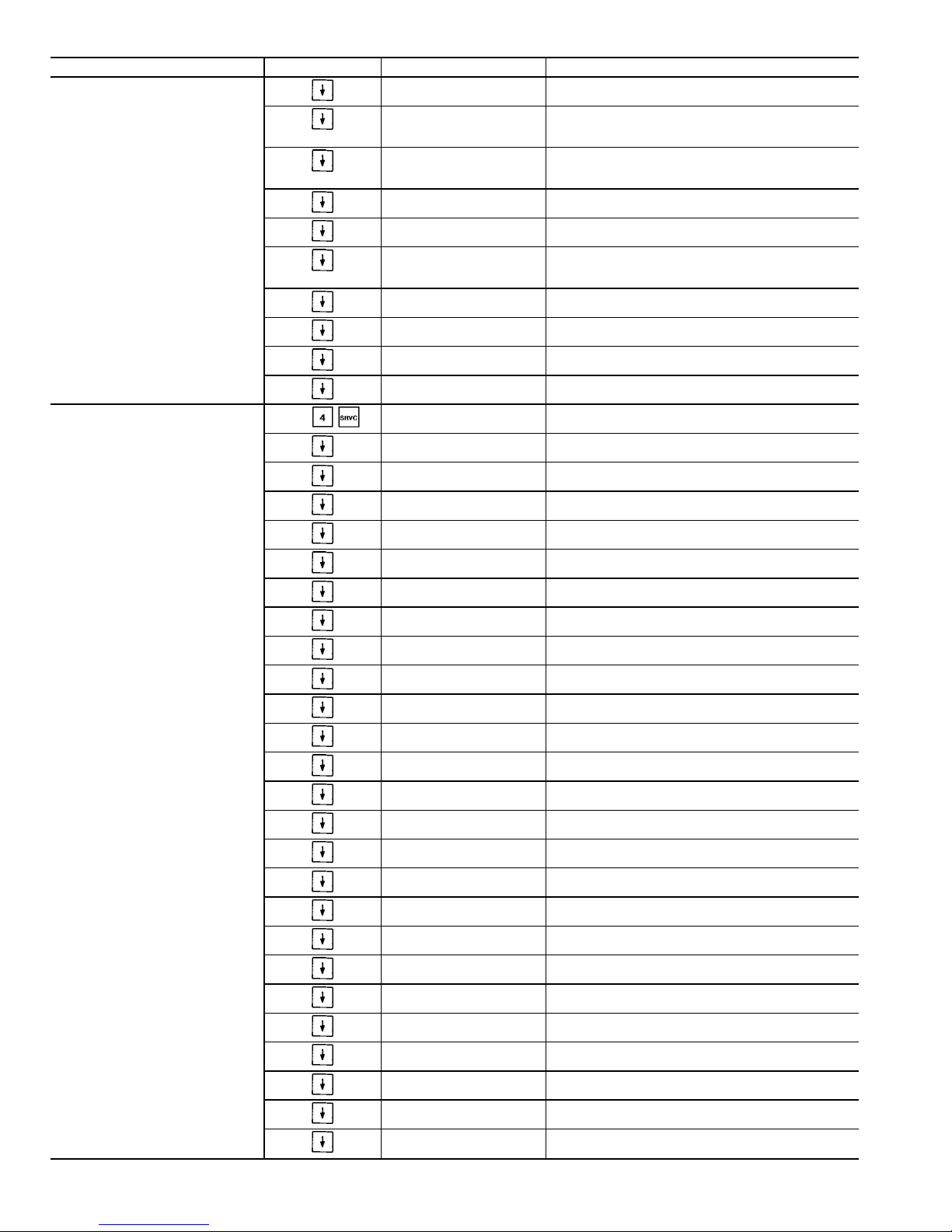
Table 19 — Service Function and Subfunction Directory (cont)
SUBFUNCTION KEYPAD ENTRY DISPLAY COMMENT
3 Options Configuration 2 (cont)
Ramp Load Select
x
0 = Disabled, 1 = Enabled (Default)
See page 8
Clock Control Select
x
0 = No clock control (Default)
1 = Local clock control
65 = CCN Clock Control
Ice Configuration Selectx0 = Disabled (Default)
1 = Clock Control
2 = Demand Limit Control
OAT Sensor Select
x
0 = Disabled, 1 = Enabled
Default: 0
Remote Alarm Select
x
0 = Disabled, 1 = Enabled
Default: 0
Alarm Reset Select
x
0 = Not selected, 1 = Selected
(Default, allows use of LOR
switch to reset alarms)
Close Control Select
x
0 = Disabled, 1 = Enabled
Default: 0. See page 7
Deadband Multiplier
x.x
Default: 1.0
Current Unbalance AlarmxAlarm at 10% imbalance; 0 = Disabled, 1 = Enabled
Default: 1
Voltage Unbalance AlarmxAlarm at 3% imbalance; 0 = Disabled, 1 = Enabled
Default: 1
4 Reset Configuration Table
COOLING RESET TYPE1See Demand Limit section, page 39
Degrees Reset at 20 mA
xx.x dF
Default: 0
COOLING RESET TYPE
2
Remote temp=No Reset
xx.x dF
Default: 20
Remote temp=Full Reset
xx.x dF
Default: 125
Degrees Reset
xx.x dF
Default: 0
COOLING RESET TYPE
3
CHW Delta T=No Reset
xx.x dF
Default: 15
CHW Delta T=Full Reset
xx.x dF
Default: 0
Degrees Reset
xx.x dF
Default: 0
COOLING RESET
Select/Enable Reset Typex0 = No Reset (Default),1=4-20 mA Reset,
2 = External Reset, 3 = Return Fluid Reset
HEATING RESET TYPE1CURRENTLY NOT SUPPORTED
Degrees Reset at 20 mA
xx.x dF
Default: 0
HEATING RESET TYPE2CURRENTLY NOT SUPPORTED
Remote temp=No Reset
xx.x dF
Default: 125
Remote temp=Full Reset
xx.x dF
Default: 20
Degrees Reset
xx.x dF
Default: 0
HEATING RESET TYPE3CURRENTLY NOT SUPPORTED
HTW Delta T=No Reset
xx.x dF
Default: 15
HTW Delta T=Full Reset
xx.x dF
Default: 0
Degrees Reset
xx.x dF
Default: 0
HEATING RESET
Select/Enable Reset Typex0 = No Reset (Default), 1 = 4-20 mA reset,
2 = External reset, 3 = Return Fluid reset
DEMAND LIMIT See Demand Limit section, page 39
Demand Limit at 20 mA
xxx.x%
Enter 0-100, Default: 0%
32
Page 33
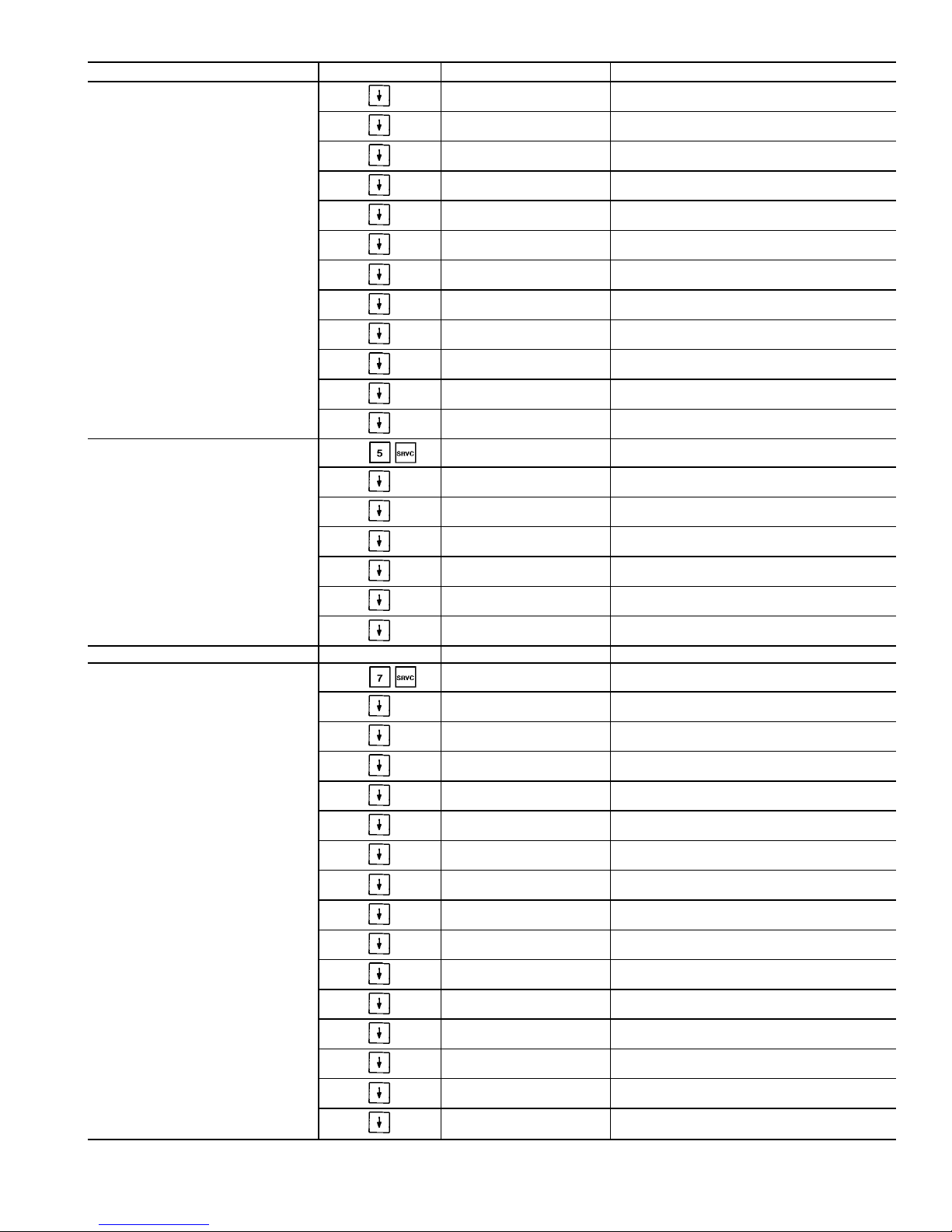
Table 19 — Service Function and Subfunction Directory (cont)
SUBFUNCTION KEYPAD ENTRY DISPLAY COMMENT
4 Reset Configuration Table (cont)
Demand Limit Select
x
0 = None (Default), 1 = Two step switch,
2 = 4-20 mA, 3 = CCN Loadshed
Loadshed Group Numberx0-99, Default: 0
Loadshed Demand Delta
xxx%
0-60%,Default: 0
Maximum Loadshed Time
xx min
0-120 min, Default: 60 min
WATER VALVE PID
Proportional PID Gain
x.x
Default = 1.0
Adjustable from -20.0 to 20.0
Integral PID Gain
x.x
Default = 0.1
Adjustable from -20.0 to 20.0
Derivative PID Gain
x.x
Default = 0.0
Adjustable from -20.0 to 20.0
AIR MOTOR MASTER
PID
Proportional PID Gain
x.x
Default = 1.0
Adjustable from -20.0 to 20.0
Integral PID Gain
x.x
Default = 0.1
Adjustable from -20.0 to 20.0
Derivative PID Gain
x.x
Default = 0.0
Adjustable from -20.0 to 20.0
5 Factory Configuration Codes
FACTORY CODES
Configuration Code 1
xxxxxxxx
Factory set. See Table 22.
Configuration Code 2
xxxxxxxx
Factory set. See Table 22.
Configuration Code 3
xxxxxxxx
Factory set. See Table 22.
SERVICE CODES
Configuration Code 4
xxxxxxxx
Factory set. See Table 22.
Configuration Code 5
xxxxxxxx
Factory set. See Table 22.
6 NOT USED
7 Transducer Calibration
CALIBRATION OFFSET See Pressure Transducer Calibration, page 59
CIRCUIT A PRESSURE
Discharge Pressure
xxx.x PSI
Suction Pressure
xxx.x PSI
A1 Oil Pressure
xxx.x PSI
A2 Oil Pressure
xxx.x PSI
Economizer Pressure
xxx.x PSI
CALIBRATION OFFSET
CIRCUIT B PRESSURE
Discharge Pressure
xxx.x PSI
Suction Pressure
xxx.x PSI
B1 Oil Pressure
xxx.x PSI
B2 Oil Pressure
xxx.x PSI
Economizer Pressure
xxx.x PSI
Calibrate All at 0 PSIG
No
Last Calibration Date
mmm dd - yy
See Legend on page 34.
33
Page 34
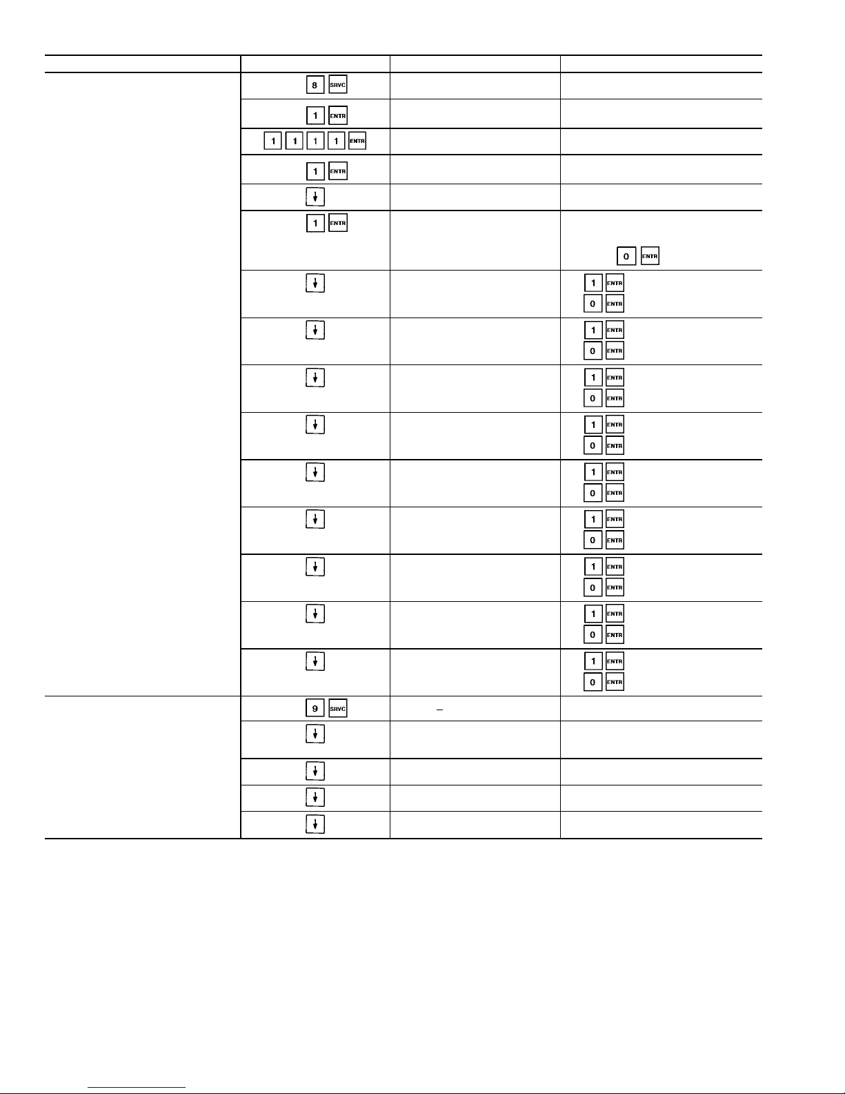
Table 19 — Service Function and Subfunction Directory (cont)
SUBFUNCTION KEYPAD ENTRY DISPLAY COMMENT
8 Manual Control Table
Manual Control Enable
Dsable
LOR switch should be in
OFF position
Password Protected
Enter:
Will be displayed if not entered
earlier in current HSIO use
Manual Control Enable
Dsable
Manual Control Enable
Enable
Switch LOR switch to Local
before proceeding
Circuit A Compressor 1
Off
Circuit A Compressor 1
On
Provided no alarms exist,
control will attempt circuit
start within 2 minutes.
Press to stop circuit.
Circuit A Compressor 2
Off
to enable,
to stop
Circuit A Loader 1
Off
to enable,
to stop
Circuit A Loader 2
Off
to enable,
to stop
Circuit A Min Load Valve
Off
to enable,
to stop
Circuit B Compressor 1
Off
to enable,
to stop
Circuit B Compressor 2
Off
to enable,
to stop
Circuit B Loader 1
Off
to enable,
to stop
Circuit B Loader 2
Off
to enable,
to stop
Circuit B Min Load Valve
Off
to enable,
to stop
9 Dual Chiller Configuration
MST SLV
Master/Slave Select
0/1/2
0 = Disabled
1 = Master
2 = Slave
Slave Address
0
Default = 0
Adjustable from 0-236
Lead/Lag Balance
0/1
0 = Disabled
1 = Enabled
Lead/Lag Balance Delta
xxx hours
Default = 168
Adjustable from 40-400
LEGEND
CCN — Carrier Comfort Network
CHW — Chilled Water
CPM — Compressor Protection Module
HSIO — Standard Keypad
HTW — Hot Water
LOR — Local/Off/Remote
MOP — Maximum Operating Pressure
OAT — Outdoor-Air Temperature
PID — Proportional Integral Derivative
34
Page 35
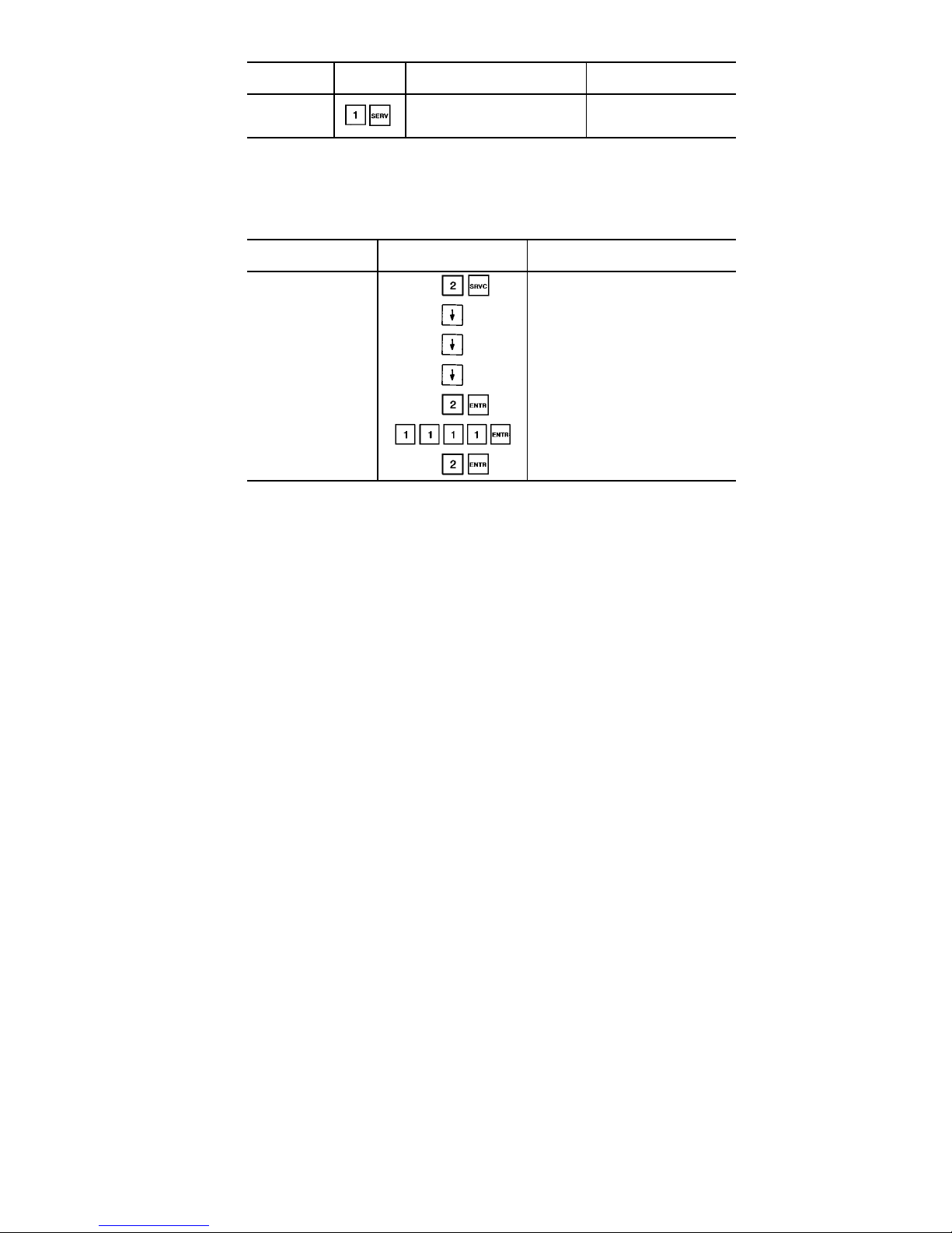
Table 20 — Displaying Current Software Version
FUNCTION
KEYPAD
ENTRY
DISPLAY COMMENT
Software
Version
Software CESR_500100 Ver
XXX
Carrier Software Part
Number, where XXX is
the revision number.
Table 21 — Compressor Lead/Lag Configuration
SUB-FUNCTION KEYPAD
ENTRY
DISPLAY
Options
Configuration 1
Cooler Fluid Select
1
Min. Load Valve Select
Dsable
Loading Sequence Select
1
Lead/Lag Sequence Select
1
PASSWD PROTECTED FUNC
Enter Password:
Lead/Lag Sequence Select
0
Lead/Lag Sequence Select
2
NOTE: Configurationsmay be modified afterentering the password.Thepassword is only
required to be entered once. After a period of 10 minutes of no HSIO activity, the user is
automatically logged out and the control requires that the password be entered on the
next use.
35
Page 36

Table 22 — Factory and Service Configuration Code Values
UNIT MODEL NUMBER CONF. CODE 1* CONF. CODE 2 CONF. CODE 3 CONF. CODE 4 CONF. CODE 5
30GX080 11460010 13900000 00000170 15400521 12000093
30GX090,105 11560010 13900000 00000180 15400521 12000093
30GX106 11560010 13900000 00000180 15400521 14000095
30GX115 11660010 13900000 00000190 15400521 14000095
30GX125 11660010 14600000 00000161 15400521 14000095
30GX136 11660010 15600000 00000162 15400521 14000095
30GX150 11560010 18000000 00000095 15400521 16000097
30GX151 11800010 15600000 00000176 15400521 07000088
30GX160 11660010 18000000 00000105 15400521 16000097
30GX161 11800010 16600000 00000177 15400521 07000088
30GX175 11800010 18000000 00000119 15400521 07000088
30GX176 11800010 18000000 00000119 15400521 03000084
30GX205 12663910 18000000 00000145 15400521 07000088
30GX206 12803910 16600000 00000217 15400521 09000090
30GX225 12804610 18000000 00000166 15400521 07000088
30GX226 12804610 18000000 00000166 15400521 09000090
30GX250 12806610 18000000 00000186 15400521 09000090
30GX251 12808010 16600000 00000258 15400521 05000086
30GX265 12808010 18000000 00000200 15400521 05000086
30HXA076 31390010 13900000 00000183 15200521 02000063
30HXA086 31460010 13900000 00000190 15200521 02000063
30HXA096 31560010 13900000 00000200 15200521 02000063
30HXA106 31660010 13900000 00000210 15200521 02000063
30HXA116 31660010 14600000 00000181 15200521 02000063
30HXA126 31660010 15600000 00000182 15200521 02000063
30HXA136 31800010 15600000 00000196 15200521 02000063
30HXA146 31800010 16600000 00000197 15200521 02000063
30HXA161 31800010 15600000 00000196 15200521 02000063
30HXA171 31660010 18000000 00000125 15200521 02000063
30HXA186 31800010 18000000 00000139 15200521 02000063
30HXA206 32663910 18000000 00000165 15200521 02000063
30HXA246 32805610 18000000 00000196 15200521 02000063
30HXA261 32806610 18000000 00000206 15200521 02000063
30HXA271 32808010 18000000 00000220 15200521 02000063
30HXC076 21390010 13900000 00000173 12200521 00000058
30HXC086 21460010 13900000 00000180 12200521 00000058
30HXC096 21560010 13900000 00000190 12200521 00000058
30HXC106 21660010 13900000 00000200 12200521 00000058
30HXC116 21660010 14600000 00000171 12200521 00000058
30HXC126 21660010 15600000 00000172 12200521 00000058
30HXC136 21800010 15600000 00000186 12200521 00000058
30HXC146 21800010 16600000 00000187 12200521 00000058
30HXC161 21800010 15600000 00000186 12200521 00000058
30HXC171 21660010 18000000 00000115 12200521 00000058
30HXC186 21800010 18000000 00000129 12200521 00000058
30HXC206 22663910 18000000 00000155 12200521 00000058
30HXC246 22805610 18000000 00000186 12200521 00000058
30HXC261 22806610 18000000 00000196 12200521 00000058
30HXC271 22808010 18000000 00000210 12200521 00000058
*Unit Type will be listed as air cooled, water cooled, or remote split system. Unit type is first digit in
Configuration Code1andis 1 for 30GX units,2for 30HXC units, and 3for30HXA cooling onlychillers.
For other options, see Table 19 under the Service subfunction. A label listing configuration codes is
located on the control box door or panel.
36
Page 37

Table 23 — Entering Configuration Codes
KEYPAD ENTRY DISPLAY RESPONSE
FACTORY CODES
Configuration Code 1
00000000
Configuration Code 1
21660010
Configuration Code 2
00000000
Configuration Code 2
13900000
Configuration Code 3
00000000
Configuration Code 3
00000200
SERVICE CODES
Configuration Code 4
00000000
Configuration Code 4
12200521
Configuration Code 5
00000000
Configuration Code 5
00000058
SCHEDULE FUNCTION — This function provides a means
to automatically switch the chiller from an occupied mode
to an unoccupied mode. Refer to Table 24 for a complete
description of the function.
The schedules consist of 8 user-configurable occupied time
periods. The control supports time schedules for local control, remote control and ice building. These time periods can
be flagged to be in effect or not in effect on each day of the
week. The day begins at 00.00 and ends at 24.00. The machine is in unoccupied mode unless a scheduled time period
is in effect. If an occupied period is to extend past midnight,
it must be programmed in the following manner: occupied
period must end at 24:00 hours (midnight); a new occupied
period must be programmed to begin at 00:00 hours.
NOTE: This is true only if the occupied period starts at 00:00
(midnight). If the occupied period starts at a time other than
midnight, then the occupied period must end at 24:00 hours
(midnight) and new occupied period must be programmed
to start at 00:00 in order for the chiller to stay in the occupied mode past midnight. Each time schedule can be overridden to keep the chiller in an Occupied mode for 1, 2, 3 or
4 hours on a one-time basis.
Dual Set Point Control — This feature can be enabled to
allow the use of a second or unoccupied cooling set point.
The function can be either switch controlled or clock controlled. To enable switch control, set the Cooling Setpoint
selection under to 1. See page 72 or 73 of Field
Wiringsection, depending on unit type, for switch input wir-
ing to the PSIO-2 module. Configure Cool Setpoint 2 under
to the desired value. The unit will then control leav-
ing water temperature to Cool Setpoint 2 when the switch
input is closed. To enable clock control, set the Cooling
Setpoint selection under to 2. Set Cool Setpoint 2 to
the desired unoccupied value. Using , configure lo-
cal operating schedules for the desired occupied and unoccupied time periods. The unit will then control leaving water
temperature to Cool Setpoint 2 during unoccupied time
periods.
37
Page 38
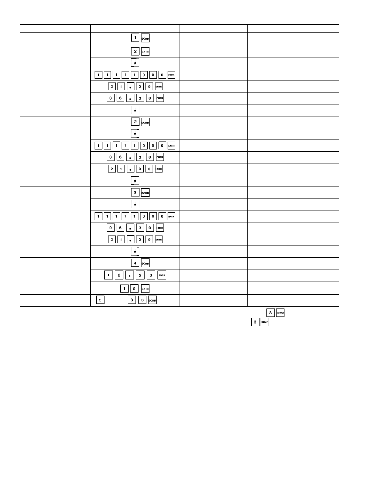
Table 24 — Schedule Function and Subfunction Directory
SUBFUNCTION KEYPAD ENTRY DISPLAY COMMENT
1 Ice Build Schedule*
SCHEDULES: OCCPC01S
Timed Override: 00
Extended Occupied Time
SCHEDULES: OCCPC01S
Timed Override: 02
Two hour override entered
MTWTFSSH OCC UNOCC
01- 00000000 00:00 00:00
Displays current stored schedule
(First 2 numbers are schedule, 01-08)
MTWTFSSH OCC UNOCC
01- 11111000 00:00 00:00
Monday-Friday now occupied
MTWTFSSH OCC UNOCC
01- 11111000 21:00 00:00
Occupied time now set
MTWTFSSH OCC UNOCC
01- 11111000 21:00 06:30
Unoccupied time now set
Ice Build schedule completed
MTWTFSSH OCC UNOCC
02- 00000000 00:00 00:00
Can enter up to 7
additional ice build schedules
2 Local Schedule†
SCHEDULES: OCCPC02S
Timed Override: 00
Extended Occupied Time
MTWTFSSH OCC UNOCC
01- 00000000 00:00 00:00
Displays current stored schedule
(First 2 numbers are schedule, 01-08)
MTWTFSSH OCC UNOCC
01- 11111000 00:00 00:00
Monday-Friday now occupied
MTWTFSSH OCC UNOCC
01- 11111000 06:30 00:00
Occupied time now set
MTWTFSSH OCC UNOCC
01- 11111000 06:30 21:00
Unoccupied time now set
Local schedule completed
MTWTFSSH OCC UNOCC
02- 00000000 00:00 00:00
Can enter up to 7
additional local schedules
3 Remote Schedule
(Currently Not
Used)
SCHEDULES: OCCPC65S
Timed Override: 00
Extended Occupied Time
MTWTFSSH OCC UNOCC
01- 00000000 00:00 00:00
Displays current stored schedule
(First 2 numbers are schedule, 01-08)
MTWTFSSH OCC UNOCC
01- 11111000 00:00 00:00
Monday-Friday now occupied
MTWTFSSH OCC UNOCC
01- 11111000 06:30 00:00
Occupied time now set
MTWTFSSH OCC UNOCC
01- 11111000 06:30 21:00
Unoccupied time now set
Remote schedule completed
MTWTFSSH OCC UNOCC
02- 00000000 00:00 00:00
Can enter up to 7
additional remote schedules
4 Holiday Configuration**
HOLIDAYS : HOLDY_01
Starts on 00/00 00 days
Can configure holiday start day
and duration
HOLIDAYS : HOLDY_01
Starts on 12/23 00 days
Start of holiday set
HOLIDAYS : HOLDY_01
Starts on 12/23 10 days
Holiday duration set
5-33 Holiday Configuration
through
HOLIDAYS : HOLDY_02
Starts on 00/00 00 days
Allows configuration of 29
additional holiday periods
*Ice configuration select must be set to 1 for clock control. The ice configuration can be accessed by pressing and scrolling down.
†Clock control select must be set to 1 for clock control. The clock control can be accessed by pressing and scrolling down.
**The BROADCAST function (BRODEFS table) must be activated (change to 9YES9 and download) when using the LID-2B controller, Building
Supervisor or ComfortWorks™ software for the control to recognize holidays.
38
Page 39
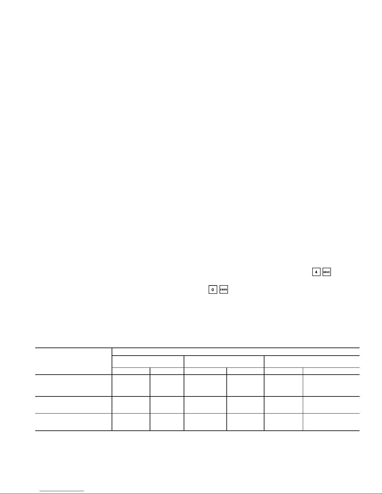
Temperature Reset — The control system is capable
of providing leaving fluid temperature reset based on return
fluid temperature. Because the temperature difference between leaving and return temperature is a measure of the
building load, return fluid temperature reset is essentially an
average building load reset method.
Under normal operation, the chiller maintains a constant
leaving fluid temperature approximately equal to the chilled
fluid set point. As building load drops from 100% down to
0%, entering cooler fluid temperature drops in proportion to
load. Thus, the temperature drop across the cooler drops from
a typical 10° F (5.5° C) at full load to a theoretical 0° F
(0° C) at no load. See Fig. 8.
At partial load, leaving chilled fluid temperature may be
lower than required. If this is allowed to increase (reset), the
efficiency of the chiller increases. Amount of reset can be
defined as a function of cooler temperature drop. This is a
simple linear function that requires 3 pieces of input data for
the set function that will vary depending on measurement
method used. See the following sections and Table 25.
NOTE: Reset set points are not accessible unless the reset
function is enabled first. The Control Point will be recalculated taking into account the set point plus the amount of
reset. This is done as a field configuration. Select one of the
3 choices for type of reset: Return Fluid Reset, External Temperature Reset, or 4 to 20 mA Signal Reset. See Table 25.
If dual set point control is enabled, the amount of reset is
applied to whichever set point is in effect at the time.
Tables 26-28 demonstrate how to activate reset.
EXTERNAL TEMPERATURE RESET — In this example,
the unit set point is reset from full load at 90 F (32 C) to a
maximum reset value of 10° F (5.5° C) at 25 F (−6.7 C)
outdoor ambient. This means that if the chilled fluid set point
is 44 F (6.7 C), there is no reset if the temperature is 90 F
(32 C). At a temperature of 25 F (−6.7 C), the chilled fluid
set point would be reset to 54 F (12.2 C). See Fig. 8 and
T able26.Afield-suppliedoutdoorairthermistormustbeconnected to PSIO-2 as shown in Fig. 37.
To activate this function for space temperature reset leave
both the External Reset Sensor Select and the OAT Sensor
Select at 0, and change the Select/Enable Reset Type to 2,
following the procedure in Table 26.
EXTERNALLY POWERED RESET (4 to 20 mA) — In this
example, the unit set point is reset from full load at 4 mA to
a maximum reset value of 10° F (5.5° C) at 20 mA. See
Fig. 9 and Table 27.
RETURN FLUID TEMPERATURE RESET — In this example, the unit set point is reset from full load based on the
chilled fluid return temperature. The example uses a reset
value of 10 degrees at full reset. Full reset is at a 2-degree
temperature difference across the cooler and no reset would
be at a 10° F difference across the cooler. See Fig. 10 and
Table 28.
Demand Limit — Demand Limit is a feature that allows
the unit capacity to be limited during periods of peak energy
usage. There are 3 types of demand limiting which can be
configured. The first type is through 2 switch inputs, which
will reduce the maximum capacity to 2 user-configurable percentages. The second type is bya4to20mAsignal input
which will reduce the maximum capacity linearly between
100% ata4mAinput signal (no reduction) down to the userconfigurable level at a 20 mA input signal. The third type
uses the CCN Loadshed module and has the ability to limit
the current operating capacity to maximum and further reduce the capacity if required.
To use Demand Limit, select the type of demand limiting
to use. Then configure the Demand Limit set points based on
the type selected.
DEMAND LIMIT (Switch Controlled, 30GX only) — In this
example, demand limit by switch control will be configured
and the switch set points will be set at 75% and 40%. Capacity steps are controlled by 2 relay switch inputs field wired
to PSIO-2, terminal 28 for switch 1 and terminal 25 for switch
2. See Table 29.
For Demand Limit by switch control, closing the first stage
demand limit contact will put the unit on the first demand
limit level. The unit will not exceed the percentage of capacity entered as Demand Switch 1 set point. Closing contacts on the second demand limit switch prevents the unit
from exceeding the capacity entered as Demand Switch 2
set point. The demand limit stage that is set to the lowest
demand takes priority if both demand limit inputs are closed.
If the demand limit percentage does not match unit staging,
the unit will limit capacity to the closest capacity stage.
To Disable Demand Limit: Enter as shown
in Table 29. Scroll down to Demand Limit Select and press
to select no Demand Limit control.
Table 25 — Temperature Reset Set Point Limits
INPUT DATA DESCRIPTION
MEASUREMENT METHOD
Type 1 — 4-20 mA
(With 500-Ohm Resistor)
Type2—OAT/Occupied Space
(External Sensor)
Type 3 — Return Fluid
Variable Limits Variable Limits Variable Limits
Maximum Reset Amount —
Allowable range for maximum
amount which LWT set point
is reset.
Degrees Reset
at 20 mA
(−30 to 30 F)
−34 to −1 C
Degrees Reset (−30 to 30 F)
−34 to −1 C
Degrees Reset (−30 to 30 F)
−34 to −1 C
Maximum Reset Reference —
Temperature at which
maximum reset occurs.
— — Remote temp =
Full Reset
(20 to 125 F)
−7 to 52 C
CHW Delta T =
Full Reset
(0 to 15 degrees F)
0to8°C
cooler temperature rise
Minimum Reset Reference —
Temperature at which
no reset occurs.
— — Remote temp =
No Reset
(20 to 125 F)
−7 to 52 C
CHW Delta T =
No Reset
(0 to 15 degrees F)
0to8°C
cooler temperature rise
LEGEND
CHW — Chilled Water
OAT — Outdoor-Air Temperature
LWT — Leaving Fluid Temperature
39
Page 40
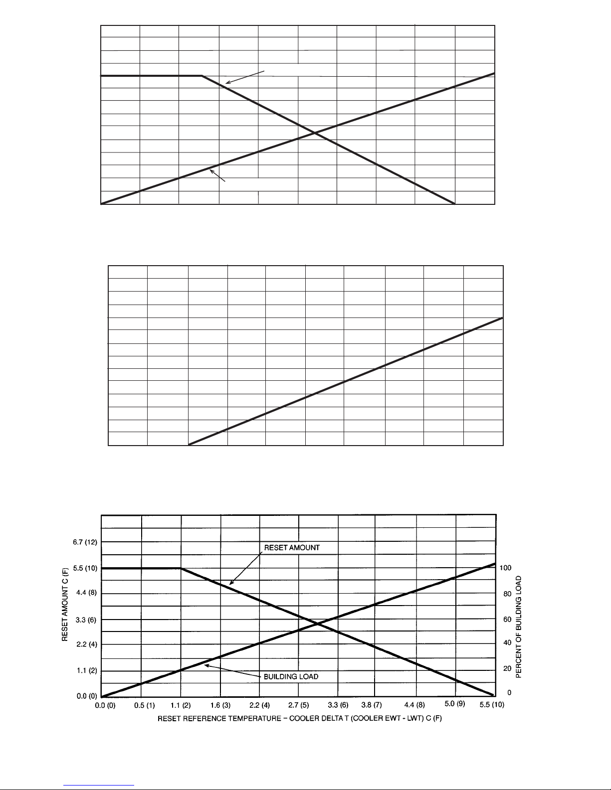
-18 (0) -12 (10) -7 (20) -1 (30) 4 (40) 10 (50) 16 (60)
21 (70) 27 (80)
32 (90)
38(100)
RESET REFERENCE TEMPERATURE-OUTDOOR AIR OR SPACE TEMPERATURE THERMISTOR C (F)
100
80
60
40
20
0
0.0 (0)
1.1 (2)
2.2 (4)
3.3 (6)
4.4 (8)
5.5 (10)
6.7 (12)
RESET AMOUNT C (F)
RESET AMOUNT
BUILDING LOAD
PERCENT BUILDING LOAD
Fig. 8 — Cooling External Temperature Reset
0 (0)
2 (1)
4 (2)
6 (3)
8 (4)
10 (5)
12 (6)
14 (7)
16 (8)
18 (9)
20 (10)
RESET REFERENCE – 4-20 mA SIGNAL INPUT (VOLTS DC)
0 (0)
1.1 (2)
2.2 (4)
3.3 (6)
4.4 (8)
5.5 (10)
6.7 (12)
RESET AMOUNT C (F)
Fig.9—4to20mACooling Temperature Reset
Fig. 10 — Cooling Return Water Reset
40
Page 41
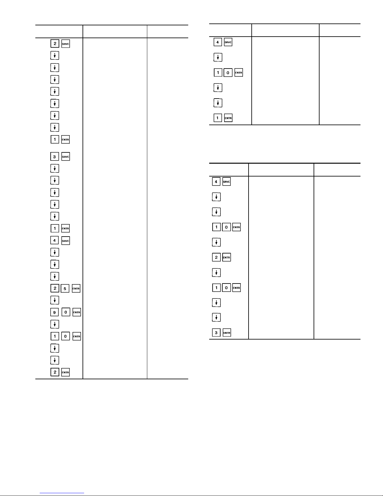
Table 26 — Setting External Temperature Reset
KEYPAD
ENTRY
DISPLAY
RESPONSE
COMMENTS
Cooler Fluid Select
1
Min. Load Valve Select
Disable
Loading Sequence Select
1
Lead/Lag Sequence Select
1
Head Press. Control Type
0
Motormaster Select
0
Water Valve Type
0
Ext. Reset Sensor Select
0
Ext. Reset Sensor Select1Outdoor Ambient
sensor selected
for reset
Cooling Setpoint Select
0
Heating Setpoint Select
0
Ramp Load Select
0
Clock Control Select
1
Ice Configuration Select
0
OAT Sensor Select
0
OAT Sensor Select
1
OAT sensor
enabled
COOLING RESET TYPE
1
Degrees Reset at 20 mA
0.0 dF
COOLING RESET TYPE
2
Remote temp = No Reset
20.0 dF
Remote temp = No Reset
25.0 dF
Remote temp = Full Reset
125.0 dF
Remote temp = Full Reset
90.0 dF
Degrees Reset
0.0 dF
Degrees Reset
10.0 dF
COOLING RESET Scroll down
to this point.
Select/Enable Reset Type
0
Select/Enable Reset Type2External reset
selected
Table 27 — Setting Externally Powered Reset
KEYPAD
ENTRY
DISPLAY
RESPONSE
COMMENTS
COOLING RESET TYPE
1
Degrees Reset at 20 mA
0.0 dF
Degrees Reset at 20 mA
10.0 dF
COOLING RESET Scroll down to
this point
Select/Enable Reset Type
0
Select/Enable Reset Type14-20 mA reset
selected
Table 28 — Setting Return Fluid
Temperature Reset
KEYPAD
ENTRY
DISPLAY
RESPONSE
COMMENTS
COOLING RESET TYPE
1
COOLING RESET TYPE3Scroll down
to this point.
CHW Delta T = No Reset
15.0 dF
CHW Delta T = No Reset
10.0 dF
CHW Delta T = Full Reset
0.0 dF
CHW Delta T = Full Reset
2.0 dF
Degrees Reset
0.0 dF
Degrees Reset
10.0 dF
COOLING RESET
Select/Enable Reset Type
0
Select/Enable Reset Type3Return Fluid reset
selected
41
Page 42
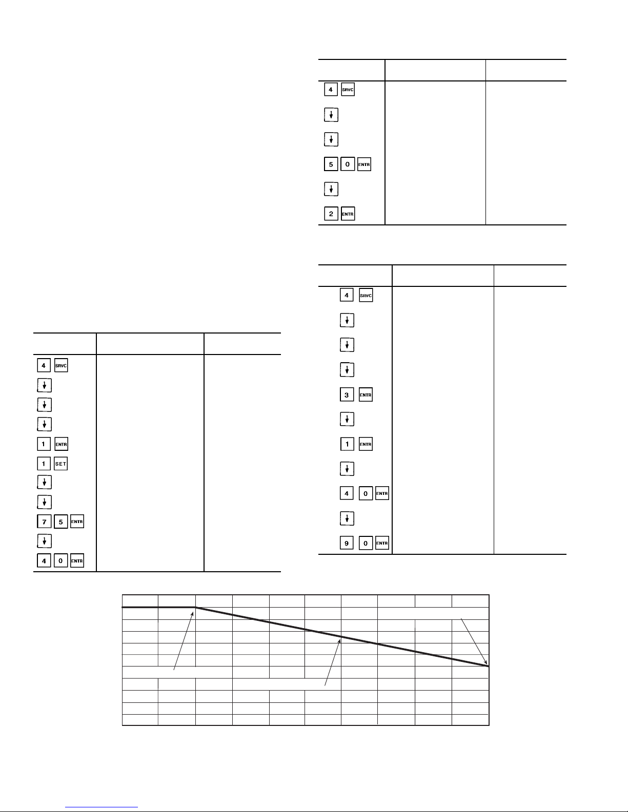
EXTERNALLY POWERED DEMAND LIMIT (4 to 20 mA
Controlled) — In this example, the 4 to 20 mADemandLimit
will be configured and the 20 mA demand limit percentage
will be set to 50%. See Table 30 and Fig. 11.
DEMAND LIMIT (CCN Loadshed Controlled) — In this
example, the CCN Loadshed Demand Limit will be configured. The loadshed group will be set to 1, demand delta will
be set to 40% and the maximum loadshed time will be set to
90 minutes. See Table 31.
The Loadshed Group number is established by the CCN
system designer. The PIC (product integrated control) will
respond to a Redline command from the Loadshed control.
When the Redline command is received, the current stage of
capacity is set to the maximum stages available. Should the
loadshed control send a Loadshed command, the PIC will
reduce the current stages by the value entered for Loadshed
Demand delta. For the above example the Loadshed Demand delta is 40%. If the chiller is operating at 80% of total
capacity when a Redline command is received, the maximum available capacity is set to 80%. WhenaLoadshedcommand is received, the chiller capacity will be reduced by 40%.
The chiller can now operate at a total capacity of no more
than 48% [80% − (80% x 40%)] until a Cancel Redline or
Cancel Loadshed command is received. The control will disable the Redline/Loadshed command if no Cancel command
has been received within the configured maximum loadshed
time limit.
Table 29 — Setting Switch-Controlled Demand Limit
KEYPAD
ENTRY
DISPLAY
RESPONSE
COMMENTS
COOLING RESET
TYPE 1
DEMAND LIMIT Scroll down to this
point
Demand Limit at 20 mA
0.0%
Demand Limit Select
0
Demand Limit Select
1
Two step switch
configured
COOLING
DEMAND LIMIT Scroll down to this
point
Demand Switch 1 Setpoint
80.0%
Demand Switch 1 Setpoint
75.0
Demand Switch 2 Setpoint
50.0%
Demand Switch 2 Setpoint
40.0%
Configuration
complete
Table 30 — Setting Demand Limit
(4 to 20 mA Controlled;
2 to 10 vdc With 500-Ohm Resistor)
KEYPAD
ENTRY
DISPLAY
RESPONSE
COMMENTS
COOLING RESET
TYPE 1
DEMAND LIMIT Scroll down to this
point
Demand Limit at 20 mA
0.0%
Demand Limit at 20 mA
50.0%
Demand Limit Select
0
Demand Limit Select
2
4-20 mA control
configured
Table 31 — Setting Demand Limit
(CCN Loadshed Controlled)
KEYPAD
ENTRY
DISPLAY
RESPONSE
COMMENTS
COOLING RESET TYPE
1
DEMAND LIMIT Scroll down to
this point
Demand Limit at 20 mA
0.0%
Demand Limit Select
0
Demand Limit Select
3
CCN Loadshed
control configured
Loadshed Group Number
0
Loadshed Group Number
1
Loadshed Demand Delta
0
Loadshed Demand Delta
40%
Maximum Loadshed Time
60 min
Maximum Loadshed Time
90 min
Configuration
complete
50% CAPACITY AT 20 mA
75% CAPACITY AT 12 mA
100% CAPACITY AT 4 mA
0 (0)
2 (1)
4 (2)
6 (3)
8 (4)
10 (5)
12 (6)
14 (7)
16 (8) 18 (9)
20 (10)
DEMAND LIMIT SIGNAL – 4 - 20 mA INPUT (VOLTS DC)
100
80
60
40
20
0
MAX. ALLOWABLE LOAD (%)
Fig. 11—4to20mADemand Limiting
42
Page 43
TROUBLESHOOTING
The 30GX,HX screw chiller control has many features to
aid in troubleshooting. By using the keypad and display module and the Status function, operating conditions of the chiller
are displayed while the unit is running. The Test function
allows for operational checkout of compressor loaders, fans,
EXVs, solenoids, and other components while the chiller is
stopped. TheServicefunctiondisplayshowconfigurable items
are configured and provides a manual control mode where
the compressors can be started and loaded. If an operating
fault is detected, an alarm is generated and an alarm code
is displayed under the subfunction along with an
explanation of the fault. Up to 10 current alarm codes are
stored under this subfunction. For checking specific items,
see Table 10.
Checking Display Codes — To determine how the
machine has been programmed to operate, check the diagnostic information displayed in the Status function and the
configuration information displayed in the Service function.
Unit Shutoff — To shut the unit off, move the LOCAL/
OFF/REMOTE switch to OFF position. All compressors and
solenoids stop immediately.
Complete Unit Stoppage — Complete unit stoppage
can be caused by any of the following conditions:
• cooling load satisfied
• remote on/off contacts open
• programmed schedule
• emergency stop command from CCN
• general power failure
• blown fuse in control power feed disconnect
• open control circuit fuse(s)
• LOCAL/OFF/REMOTE switch moved to OFF position
• freeze protection trip
• low flow protection trip
• open contacts in chilled water flow switch (optional)
• Open contacts in any auxiliary interlock. Terminals that
are jumpered from factory are in series with control switch.
Opening the circuit between these terminals places unit in
Stop mode, similar to moving the control switch to OFF
position. Unit cannot start if these contacts are open. If
they open while unit is running, the unit stops
• cooler entering or leaving fluid thermistor failure
• low/high transducer supply voltage
• loss of communications between processor module and other
control modules
• low refrigerant pressure
• off-to-on delay is in effect
If a stoppage occurs more than once as a result of any
of the above safety devices, determine and correct the
cause before attempting another restart.
Single Circuit Stoppage — Single circuit stoppage
can be caused by the following:
• low oil pressure
• open contacts in high pressure switch
• low refrigerant pressure
• thermistor failure
• transducer failure
• alarm condition from CPM module
• Overload relay trip. Stoppage of one circuit by a safety
device action does not affect other circuit. When a safety
device trips, the circuit is shut down immediately and EXV
closes
If a stoppage occurs more than once as a result of any
of the preceding safety devices, determine and correct
the cause before attempting another restart.
Restart Procedure — After the cause for stoppage has
been corrected, restart is either automatic or manual, depending on the fault. Manual reset requires that the alarm(s)
be reset via the HSIO. Press and then to
clear manual reset alarms. If the Alarm Reset Select feature
is selected ( ), a manual reset alarm can also be reset
by switching the LOR switchfromLOCAL/REMOTEtoOFF
and back to LOCAL/REMOTE again. If an alarm was from
the CPM module, depress theresetbuttonlocatedontheHSIO
or fuse bracket before clearing the alarm through the HSIO.
Some typical fault conditions are described in Table 32. For
a complete list of fault conditions, codes, and reset type, see
Table 33.
POWER FAILURE EXTERNAL TO THE UNIT — Unit
restarts automatically when power is restored.
Table 32 — Typical Stoppage Faults
and Reset Types
STOPPAGE FAULT RESET TYPE
Loss of Condenser Flow (30HXC) Manual reset
Cooler Freeze Protection
(Chilled Fluid, Low
Temperature)
Auto reset first time, manual if
repeated in same day
Chilled Fluid Pump Interlock Automatic reset (Manual for
closed contacts when pump is off)
Control Circuit Fuse Blown Unit restarts automatically when
power is restored
High-Pressure Switch Open Manual reset
Low Sat. Suction Temperature Manual reset
Low Oil Pressure Manual reset
Loss of Communications with
WSM or FSM controller
Automatic reset
LEGEND
FSM — Flotronic™ System Manager
WSM — Water System Manager
Alarms and Alerts — These are warnings of abnormal
or fault conditions, and may cause either one circuit or the
whole unit to shut down. They are assigned code numbers as
described in Table 33. The alarm descriptions are displayed
on the HSIO when the subfunction is entered. When
a communication loss occurs to a hardware point, an alert or
alarm may be generated. Refer to Table 34. The PSIO also
recognizes illegal configurations. Illegal configurations are
shown in Table 35.
Table 33 contains a detailed description of each alarm and
alert code error and possible cause. Manual reset is
accomplished by entering from the HSIO and press-
ing or moving the LOCAL/OFF/REMOTE Switch
to the OFF position, then back to LOCAL or REMOTE po-
sition (If Alarm Reset Select is enabled).
CompressorAlarm/AlertCircuit — Each compres-
sor is controlled by its own CPM processor, which closes
contacts between plug terminals PL2-3 and PL2-6 to start
the compressor. Power is supplied to the CPM logic circuit
through each compressor high-pressure switch and into plug
terminal PL2-2. If the high-pressure switch opens, the CPM
generates an alarm.
NOTE: Similar connections for each compressor can be followed on the unit wiring diagrams located on the unit.
43
Page 44
Table 33 — Alarm and Alert Codes
ALARM/ALERT
CODE
ALARM OR
ALERT
DESCRIPTION
WHY WAS THIS
ALARM GENERATED?
ACTION TAKEN
BY CONTROL
RESET
METHOD
PROBABLE
CAUSE
0 — No Alarms or Alerts
Exist
— ———
1.xx See CPM subcodes
below
Compressor A1 Failure See CPM subcodes
below
See CPM subcodes
below
Manual See CPM subcodes
below
2.xx See CPM subcodes
below
Compressor A2 Failure See CPM subcodes
below
See CPM subcodes
below
Manual See CPM subcodes
below
5.xx See CPM subcodes
below
Compressor B1 Failure See CPM subcodes
below
See CPM subcodes
below
Manual See CPM subcodes
below
6.xx See CPM subcodes
below
Compressor B2 Failure See CPM subcodes
below
See CPM subcodes
below
Manual See CPM subcodes
below
CPM SUBCODES
(xx)
x.0 — No Error — — — —
x.1 Alarm High Pressure Switch
Trip
HPS input to CPM
module open
Comp. shut down Manual/Button Loss of condenser air/
water flow. Operation
beyond chiller capability.
Liquid valve not open.
x.2 Alarm No Motor Current CPM reads less than
10% of MTA on all legs
for >3 seconds
Comp. shut down Manual/Button Power supply discon-
nected, blown fuse(s),
wiring error, contactor
not energized, faulty
current toroid, motor
overload tripped
x.25* Alarm Current Imbalance
>10% (Alarm)
CPM measures current
balance between
phases greater than
10% for 25 minutes
Circuit shut down Manual/Button Loose terminals on
power wires. Poor
power supply. Disabled
only if alarm feature is
enabled in
x.27* Alert Current Imbalance
>10% (Warning)
CPM measures current
balance between
phases greater than
10% for 25 minutes
None — Loose terminals on
power wires. Poor
power supply. Displayed
only if alarm feature is
disabled in
x.3 Alarm Current Imbalance
>18%
CPM measures current
balance between
phases greater than
18% for 25 minutes
Circuit shut down Manual/Button Loose terminals on
power wires.
Poor power supply.
x.35 Alarm Single Phase Current
Loss
CPM measures current
imbalance between
phases greater than
20%
Circuit shut down Manual/Button Blown fuse, wiring error,
loose terminals.
x.4 Alarm High Motor Current CPM detects high cur-
rent compared to MTA
setting
Comp. shut down Manual/Button Operation beyond chiller
capability, improperly
punched configuration
header, blown fuse
x.5 Alarm Ground Fault CPM detects ground
current (2.5 ± 2.0 amps)
Comp. shut down Manual/Button Motor winding(s) gone
to ground, wiring error,
loose plug connector,
current toroid plugs not
facing same direction.
x.55* Alarm Voltage Imbalance >3%
(Alarm)
CPM measures voltage
imbalance between
phases greater than 3%
for 25 minutes
Circuit shut down Manual/Button Compressor fault, local
utility supply imbalance,
Poor power supply. Displayed only if alarm feature is enabled in
x.57* Alert Voltage Imbalance >3%
(Warning)
CPM measures voltage
imbalance between
phases greater than 3%
for 25 minutes
None — Compressor fault, local
utility supply imbalance.
Displayed only if alarm
feature is disabled in
x.6 Alarm Voltage Imbalance >7% CPM measures voltage
imbalance between
phases greater than 7%
for 25 minutes
Circuit shut down Manual/Button Compressor fault, local
utility supply imbalance
x.7 Alarm Volt Phase Reversal CPM detects incoming
power supply out of
phase
Chiller shut down and
not allowed to start
Manual/Button Leads at CPM board
not connected. Supply
power not in phase;
interchange any 2
incoming leads.
x.75 Alarm Contactor Failure CPM detects min. 10%
of MTA for 10 seconds
after shutting off compressor contactor. Oil
solenoid is energized.
All remaining compressors shut down. All
loaders deenergized.
Min. load valve of affected circuit energized
(if equipped)
Manual/Button Faulty contactor, con-
tactor welded, wiring
error.
x.8 Alarm Current Phase Reversal CPM detects phase re-
versal from toroid
reading
Circuit shut down Manual/Button Multiple terminal block
power supply leads not
in phase. Toroid wire
harness crossed, toroid
not all facing same
direction
44
Page 45
Table 33 — Alarm and Alert Codes (cont)
ALARM/ALERT
CODE
ALARM OR
ALERT
DESCRIPTION
WHY WAS THIS
ALARM GENERATED?
ACTION TAKEN
BY CONTROL
RESET
METHOD
PROBABLE
CAUSE
CPM SUBCODES
(xx)
x.85 Alarm Motor Over Temperature CPM detects high motor
temperature
Comp. shut down Manual/Button Motor cooling (all) or
Economizer (2 comp.
circuits) solenoid failure,
low refrigerant charge.
x.9 Alarm Open Thermistor CPM detects open
circuit in motor temp
thermistor
Comp. shut down Manual/Button Wiring error or faulty
thermistor.†
x.95 Alarm Config. Header Fault CPM finds error with
MTAvalue punched out
in header
Comp. shut down Manual/Button Header pins on CPM
board either all or none
punched out, header not
fully seated in CPM
board.
x.10 Alarm Shorted Thermistor CPM detects short
circuit in motor tempt
thermistor
Comp. shut down Manual/Button Wiring error or faulty
thermistor.†
ALARM/ALERT
CODE
7 Alert Cir. A Discharge Gas
Thermistor Failure
Thermistor outside
range of −40 to 245 F
(−40 to 118 C) or DGT
>210 F (98.9 C)
Circuit A shut down Manual Thermistor failure, motor
cooling solenoid failure
or wiring error.
8 Alert Cir. B Discharge Gas
Thermistor Failure
Thermistor outside
range of −40 to 245 F
(−40 to 118 C) or DGT
>210 F (98.9 C)
Circuit B shut down Manual Thermistor failure, motor
cooling solenoid failure
or wiring error.
9 Alarm Cooler Leaving Fluid
Thermistor Failure
Thermistor outside
range of −40 to 245 F
(−40 to 118 C)
Chiller shut down. Automatic Thermistor failure, dam-
aged cable/wire or wiring error.
10 Alarm Cooler Entering Fluid
Thermistor Failure
Thermistor outside
range of −40 to 245 F
(−40 to 118 C).
Uses 0.1° F/% Total Capacity as rise/ton.
Automatic Thermistor failure, dam-
aged cable/wire or wiring error.
11 Alert Condenser Leaving
Fluid Thermistor Failure
Thermistor outside
range of −40 to 245 F
(−40 to 118 C)
None. Chiller continues
to run.
Automatic Thermistor failure, dam-
aged cable/wire or wiring error.
12 Alert Condenser Entering
Fluid Thermistor Failure
Thermistor outside
range of −40 to 245 F
(−40 to 118 C)
None. Chiller continues
to run.
Automatic Thermistor failure, dam-
aged cable/wire or wiring error.
15 Alert Compressor A1 High
Motor Temperature
Thermistor outside
range of −39.9 to 245 F
(−39.9 to 118 C) for 5
consecutive readings
Compressor A1 shut
down
Manual Thermistor failure, motor
cooling (all) or Economizer (2 comp. circuits)
solenoid failure.
16 Alert Compressor A2 High
Motor Temperature
Thermistor outside
range of −39.9 to 245 F
(−39.9 to 118 C) for 5
consecutive readings
Compressor A2 shut
down
Manual Thermistor failure, motor
cooling (all) or Economizer (2 comp. circuits)
solenoid failure.
17 Alert Compressor B1 High
Motor Temperature
Thermistor outside
range of −39.9 to 245 F
(−39.9 to 118 C) for 5
consecutive readings
Compressor B1 shut
down
Manual Thermistor failure, motor
cooling (all) or Economizer (2 comp. circuits)
solenoid failure.
18 Alert Compressor B2 High
Motor Temperature
Thermistor outside
range of −39.9 to 245 F
(−39.9 to 118 C) for 5
consecutive readings
Compressor B2 shut
down
Manual Thermistor failure, motor
cooling (all) or Economizer (2 comp. circuits)
solenoid failure.
21 Alert External Reset Tem-
perature Thermistor
Failure
Thermistor outside
range of −40 to 245 F
(−40 to 118 C)
Reset disabled. Runs
under normal control/
set points.
Automatic Thermistor failure or
wiring error.
22 Alert Circuit ADischarge
Pressure Transducer
Failure
Calibration offset more
than 6 PSIG or Voltage
ratio (volts read/ref. voltage) more than 99.9%
or less than 0.5%.
Circuit A shut down Automatic Transducer failure,
power supply failure or
wiring damage/error.
23 Alert Circuit B Discharge
Pressure Transducer
Failure
Calibration offset more
than 6 PSIG or Voltage
ratio (volts read/ref. voltage) more than 99.9%
or less than 0.5%.
Circuit B shut down Automatic Transducer failure,
power supply failure or
wiring damage/error.
24 Alert Circuit ASuction Pres-
sure Transducer Failure
Calibration offset more
than 6 PSIG or Voltage
ratio (volts read/ref. voltage) more than 99.9%
or less than 0.5%.
Circuit A shut down Automatic Transducer failure,
power supply failure or
wiring damage/error.
25 Alert Circuit B Suction Pres-
sure Transducer Failure
Calibration offset more
than 6 PSIG or Voltage
ratio (volts read/ref. voltage) more than 99.9%
or less than 0.5%.
Circuit B shut down Automatic Transducer failure,
power supply failure or
wiring damage/error.
26 Alert Comp A1 Oil Pressure
Transducer Failure
Calibration offset more
than 6 PSIG or Voltage
ratio (volts read/ref. voltage) more than 99.9%
or less than 0.5%.
Comp A1 shut down Automatic Transducer failure,
power supply failure or
wiring damage/error.
27 Alert Comp A2 Oil Pressure
Transducer Failure
Calibration offset more
than 6 PSIG or Voltage
ratio (volts read/ref. voltage) more than 99.9%
or less than 0.5%.
Comp A2 shut down Automatic Transducer failure,
power supply failure or
wiring damage/error.
45
Page 46
Table 33 — Alarm and Alert Codes (cont)
ALARM/ALERT
CODE
ALARM OR
ALERT
DESCRIPTION
WHY WAS THIS
ALARM GENERATED?
ACTION TAKEN
BY CONTROL
RESET
METHOD
PROBABLE
CAUSE
28 Alert Comp B1 Oil Pressure
Transducer Failure
Calibration offset more
than 6 PSIG or Voltage
ratio (volts read/ref. voltage) more than 99.9%
or less than 0.5%.
Comp B1 shut down Automatic Transducer failure,
power supply failure or
wiring damage/error.
29 Alert Comp B2 Oil Pressure
Transducer Failure
Calibration offset more
than 6 PSIG or Voltage
ratio (volts read/ref. voltage) more than 99.9%
or less than 0.5%.
Comp B2 shut down Automatic Transducer failure,
power supply failure or
wiring damage/error.
30 Alert Circuit A Economizer
Transducer Failure
Calibration offset more
than 6 PSIG or Voltage
ratio (volts read/ref. voltage) more than 99.9%
or less than 0.5%.
Circuit A shut down Automatic Transducer failure,
power supply failure or
wiring damage/error.
31 Alert Circuit B Economizer
Transducer Failure
Calibration offset more
than 6 PSIG or Voltage
ratio (volts read/ref. voltage) more than 99.9%
or less than 0.5%.
Circuit B shut down Automatic Transducer failure,
power supply failure or
wiring damage/error.
32 Alarm Transducer Supply Out-
side 4.5 to 5.5 Volts
Reference voltage measured at PSIO-1,
J7-34,35 less than 4.5 V
or greater than 5.5 V.
Chiller shut down Automatic Power supply failure or
wiring error. Low transformer voltage.
34 Alert 4-20 mA Reset Input
Out of Range
If configured and input
signal to PSIO-2,
J7-19,20(HX),
J7-22,23(GX) less than
2 mA or greater than
20 mA
Reset function disabled.
Normal set point used
Automatic Faulty signal generator,
wiring error, 500 ohm
resistor missing or not
properly installed.
35 Alert 4-20 mA Demand Limit
Input Out of Range
If configured and input
signal to PSIO-2,
J7-22,23(HX),
J7-13,14(GX) less than
2 mA or greater than
20 mA
Demand limit ignored.
Runs under normal control based on 100% demand limit.
Automatic Faulty signal generator,
wiring error, 500 ohm
resistor missing or not
properly installed.
36 Alarm Loss of Communication
with ‘‘Hardware Point’’
PSIO-1 has lost communication with one of
the points in Table 34.
See Table 34. Automatic Failed module, wiring
error, failed transformer,
loose connection plug,
wrong address
37 Alert Circuit A Low Saturated
Suction Temperature
SST reads 6 F (3.3 C)
or more below the
freeze point for 3 minutes. Point is 28 F
(−2.2 C) for water, set
point minus 8 F (4.4 C)
for brines.
Circuit A shut down Manual Low refrigerant charge,
plugged strainer, faulty
expansion valve. Low
water flow.
38 Alert Circuit B Low Saturated
Suction Temperature
SST reads 6 F (3.3 C)
or more below the
freeze point for 3 minutes. Point is 30 F
(−1.1 C) for water, cooling set point minus 8 F
(4.4 C) for brines.
Circuit B shut down Manual Low refrigerant charge,
plugged strainer, faulty
expansion valve. Low
water flow.
40 Alert Compressor A1 Low Oil
Pressure
See Note 1. Comp A1 shut down Manual Low Water Temperature,
low refrigerant charge,
plugged oil filter, closed
oil valve, bad oil solenoid, compressor oil
check valve stuck, oil
line check valve stuck,
plugged oil strainer.
41 Alert Compressor A2 Low Oil
Pressure
See Note 1. Comp A2 shut down Manual Low Water Temperature,
low refrigerant charge,
plugged oil filter, closed
oil valve, bad oil solenoid, compressor oil
check valve stuck, oil
line check valve stuck,
plugged oil strainer
42 Alert Compressor B1 Low Oil
Pressure
See Note 1. Comp B1 shut down Manual Low Water Temperature,
low refrigerant charge,
plugged oil filter, closed
oil valve, bad oil solenoid, compressor oil
check valve stuck, oil
line check valve stuck,
plugged oil strainer
43 Alert Compressor B2 Low Oil
Pressure
See Note 1. Comp B2 shut down Manual Low Water Temperature,
low refrigerant charge,
plugged oil filter, closed
oil valve, bad oil solenoid, compressor oil
check valve stuck, oil
line check valve stuck,
plugged oil strainer
44 Alarm Circuit A Condenser
Freeze Protection
(alarm ignored for brine
chillers)
For W/C chillers only, if
SCT <34 F (1.1 C)
Chiller shut down. Turn
Cond pump On if Chiller
is Off
Automatic Failed/bad discharge
pressure transducer,
refrigerant leak,
configured for watercooled condenser
46
Page 47
Table 33 — Alarm and Alert Codes (cont)
ALARM/ALERT
CODE
ALARM OR
ALERT
DESCRIPTION
WHY WAS THIS
ALARM GENERATED?
ACTION TAKEN
BY CONTROL
RESET
METHOD
PROBABLE
CAUSE
45 Alarm Circuit B Condenser
Freeze Protection
(alarm ignored for brine
chillers)
For W/C chillers only , if
SCT <34 F (1.1 C)
Chiller shut down. Turn
Cond pump On if Chiller
is Off
Automatic Failed/bad discharge
pressure transducer,
refrigerant leak,
configured for watercooled condenser
46 Alarm Cooler Freeze Protec-
tion
Cooler EWT or LWT
less than freeze point.
Freeze point is 34 F
(1.1 C) for water, cooling set point minus 8 F
(4.4 C) for brines.
Chiller shut down.
Leave Cooler pump on.
Turn Cooler pump On if
Chiller is Off.
Automatic** Faulty thermistor, low
water flow
47 Alert Circuit A High Saturated
Suction Temperature
After first 90 seconds,
SST > 55 F (12.8 C)
and EXV < 1% for
5 minutes
Circuit A shut down Manual Faulty expansion valve,
liquid level sensor or
transducer.
48 Alert Circuit B High Saturated
Suction Temperature
After first 90 seconds,
SST > 55 F (12.8 C)
and EXV < 1% for
5 minutes
Circuit B shut down Manual Faulty expansion valve,
liquid level sensor or
transducer.
49 Alarm Loss of Condenser Flow Flow switch not closed
within 1 minute after
pump is started or if
flow switch opens during normal operation for
>10 seconds
Chiller shut down Manual Low condenser water
flow, failed condenser
pump
50 Alarm Illegal Configuration x Illegal Configuration has
been entered. Correction needed.
Chiller cannot start. See
Table 35.
Manual Configuration error.
51 Alarm Initial Configuration
Required
No configuration has
been entered.
Chiller cannot start Manual Configuration omitted.
52 Alarm Unit is in Emergency
Stop
CCN command received
to shut unit down.
Chiller shut down CCN/
Automatic
Network command.
53 Alarm Cooler Pump Interlock
Failed at Start-Up
Interlock did not close
within 1 minute after
transition
Chiller shut down. Pump
turned off.
Automatic Failure of cooler pump
or controls
54 Alarm Cooler Pump Interlock
Opened Unexpectedly
Interlock opened for at
least 5 seconds during
operation
Chiller shut down. Pump
turned off.
Automatic Failure of cooler pump
or controls
55 Alarm Cooler Pump Interlock
Closed When Pump
OFF
Interlock closed when
pump relay is off
Cooler pump remains
off. Unit prevented from
starting.
Manual Failure of cooler pump
relay or interlock,
welded contacts
56 Alert Loss of Communication
with WSM
No communications
have been received by
PSIO-1 within 5 minutes
of last transmission.
WSM forces removed.
Runs under own control
Automatic Failed module, wiring
error, failed transformer,
loose connection plug,
wrong address
57 Alert Circuit A Liquid Level
Sensor Failure
Sensor reads 245 F
(118 C) or −40 F
(−40 C) with SST > 9 F
(−12.8 C)
Runs, but controls EXV
based on Disch. Superheat
Automatic Thermistor circuit open,
faulty liquid level sensor,
wiring error
58 Alert Circuit B Liquid Level
Sensor Failure
Sensor reads 245 F
(118 C) or −40 F
(−40 C) with SST > 9 F
(−12.8 C)
Runs, but controls EXV
based on Disch. Superheat
Automatic Thermistor circuit open,
faulty liquid level sensor,
wiring error
59 Alarm Compressor A1
Pre-Start Oil Pressure
Oil Pump did not build
sufficient pressure during pre-lube cycle.
Circuit cannot start Manual Low oil, oil pump failure,
oil solenoid failure, oil
transducer failure, check
valve failed open, oil
shutoff valve closed
60 Alarm Compressor A2
Pre-Start Oil Pressure
Oil Pump did not build
sufficient pressure during pre-lube cycle.
Circuit cannot start Manual Low oil, oil pump failure,
oil solenoid failure, oil
transducer failure, check
valve failed open, oil
shutoff valve closed
61 Alarm Compressor B1
Pre-Start Oil Pressure
Oil Pump did not build
sufficient pressure during pre-lube cycle.
Circuit cannot start Manual Low oil, oil pump failure,
oil solenoid failure, oil
transducer failure, check
valve failed open, oil
shutoff valve closed
62 Alarm Compressor B2
Pre-Start Oil Pressure
Oil Pump did not build
sufficient pressure during pre-lube cycle.
Circuit cannot start Manual Low oil, oil pump failure,
oil solenoid failure, oil
transducer failure, check
valve failed open, oil
shutoff valve closed
63 Alarm Circuit A&B OFF for
Alerts. Unit down
Control has shut down
both circuits due to
alerts.
None Automatic Check individual alarms
64 Alert Circuit A Loss of Charge Discharge pressure
reading <10 PSIG for
30 seconds
Circuit A shut down Manual Refrigerant leak or
transducer failure
65 Alert Circuit B Loss of Charge Discharge pressure
reading <10 PSIG for
30 seconds
Circuit B shut down Manual
66 Alarm Loss of Communication
with FSM
No communications
have been received by
PSIO-1 within 5 minutes
of last transmission.
FSM forces removed
Runs under own control
Automatic Wiring faulty or module
failure
67 Alert Circuit A High Discharge
Pressure
SCT > MCT_SP + 5 F
(2.8 C)
Circuit shut down Automatic** Faulty transducer/high
pressure switch, low/
restricted condenser
air/water flow.††
47
Page 48
Table 33 — Alarm and Alert Codes (cont)
ALARM/ALERT
CODE
ALARM OR
ALERT
DESCRIPTION
WHY WAS THIS
ALARM GENERATED?
ACTION TAKEN
BY CONTROL
RESET
METHOD
PROBABLE
CAUSE
68 Alert Circuit B High Dis-
charge Pressure
SCT > MCT_SP + 5 F
(2.8 C)
Circuit shut down Automatic** Faulty transducer/high
pressure switch, low/
restricted condenser
air/water flow.††
70 Alert High Leaving Chilled
Water Temperature
LCW read > LCW Delta
Alarm limit and total capacity is 100% and current LCW > LCW
reading 1 minute ago
Alert only. None Automatic Building load greater
than unit capacity, low
water/brine flow, or
compressor fault. Check
for other alarms or
alerts.
71 Alert Circuit A Low Oil Level Level switch input open
for 4th time in same
day.
Circuit A shut down Manual Low oil level, failed
switch, wiring error,
failed DSIO module
72 Alert Circuit B Low Oil Level Level switch input open
for 4th in same day.
Circuit B shut down Manual Low oil level, failed
switch, wiring error,
failed DSIO module
73 Alert Circuit A Low Discharge
Superheat
Superheat <5 F (2.8 C)
for 10 minutes
Circuit A shut down Manual Faulty thermistor,
transducer or EXV or
Economizer. Motor cooling solenoid stuck open.
74 Alert Circuit B Low Discharge
Superheat
Superheat <5 F (2.8 C)
for 10 minutes
Circuit B shut down Manual Faulty thermistor,
transducer or EXV or
Economizer. Motor cooling solenoid stuck open.
75 Alarm Comp. A1 Max. Oil
Delta P, check oil line
(Discharge press − Oil
press) >100 PSI for
more than 5 seconds
Comp. A1 shut down Manual Plugged oil filter, closed
oil valve, bad oil solenoid, compressor oil
check valve stuck, oil
line check valve stuck,
plugged oil strainer
76 Alarm Comp. A2 Max. Oil
Delta P, check oil line
(Discharge press − Oil
press) >100 PSI for
more than 5 seconds
Comp. A2 shut down Manual Plugged oil filter, closed
oil valve, bad oil solenoid, compressor oil
check valve stuck, oil
line check valve stuck,
plugged oil strainer
77 Alarm Comp. B1 Max. Oil
Delta P, check oil line
(Discharge press − Oil
press) >100 PSI for
more than 5 seconds
Comp. B1 shut down Manual Plugged oil filter, closed
oil valve, bad oil solenoid, compressor oil
check valve stuck, oil
line check valve stuck,
plugged oil strainer
78 Alarm Comp. B2 Max. Oil
Delta P, check oil line
(Discharge press − Oil
press) >100 PSI for
more than 5 seconds
Comp. B2 shut down Manual Plugged oil filter, closed
oil valve, bad oil solenoid, compressor oil
check valve stuck, oil
line check valve stuck,
plugged oil strainer
79 Alarm Comp. A1 Failed Oil
Solenoid
Diff. Oil pressure
>2.5 PSI during period
after oil pump starts and
before oil solenoid opens
Comp. A1 not allowed
to start
Manual Faulty oil solenoid valve
80 Alarm Comp. A2 Failed Oil
Solenoid
Diff. Oil pressure
>2.5 PSI during period
after oil pump starts and
before oil solenoid opens
Comp. A2 not allowed
to start
Manual Faulty oil solenoid valve
81 Alarm Comp. B1 Failed Oil
Solenoid
Diff. Oil pressure
>2.5 PSI during period
after oil pump starts and
before oil solenoid opens
Comp. B1 not allowed
to start
Manual Faulty oil solenoid valve
82 Alarm Comp. B2 Failed Oil
Solenoid
Diff. Oil pressure
>2.5 PSI during period
after oil pump starts and
before oil solenoid opens
Comp. B2 not allowed
to start
Manual Faulty oil solenoid valve
LEGEND
CCN — Carrier Comfort Network
CPM — Compressor Protection Module
DGT — Discharge Gas Temperature
EWT — Entering Water Temperature
EXV — Electronic Expansion Valve
FSM — Flotronic™ System Manager
HPS — High-Pressure Switch
LCW — Leaving Chilled Water
LWT — Leaving Water Temperature
MCT
SP — Maximum Condensing Temperature Set Point
MTA — Compressor Must Trip Amps
SCT — Saturated Condensing Temperature
SST — Saturated Suction Temperature
W/C — Water-Cooled
WSM — Water System Manager
*Current and voltage imbalance alarms x.25 and x.55 may be changed to
warnings x.27 and x.57 after successful start-up of the chiller.
†Compressors are equipped with 2 motor winding temperature ther-
mistors. Verify first thatthe problem isnot a wiringerror before usingbackup
thermistor.
**Reset automatic first time, manual if repeated on the same date.
††Note that the high-pressureswitch should trip before this alertis generated.
Check HPS operation if this alert is generated.
NOTES:
1. Low Oil Pressure Alert Criteria and Set Points
Where: Pd= Discharge pressure, Ps= Suction pressure,
Po= Oil pressure and Pe= Economizer pressure
Two oil pressure set points are used. Oil Set point 1 is always 15 psig.
a. If (Pd−Ps) <125, then Oil Set point 2 = 0.235 x (Pd−Ps) + 0.588
b. If (Pd−Ps) > = 125 and <165, then Oil Set point2=2.0x(Pd−Ps)
− 220.0
c. If (Pd−Ps) > = 165, then Oil Set point 2 = 0.6364 x (Pd−Ps) + 5.0
The 2 set points are used by the control for the Low Oil Pressure alert trip
criteria below:
a. Oil Pressure is ignored during the first 5 seconds after a compressor is
started.
b. In period between 5 and 30 seconds after starting, the alert will begen-
erated if (Po−Pe) < [(Oil Set point 1)/30] x (Compressor Run time in
seconds) for 3 consecutive readings
c. After 30 seconds run time, the alert will be generated if:
1) (Po−Pe) < Oil Set point 1 for 15 seconds OR
2) (Po−Ps) < Oil Set point 2 for 25 seconds
2. (Po−Pe) is theOilpressure differential displayed in for Circuit A
and for Circuit B.
48
Page 49
Table 34 — Hardware Point Communications Loss/Action Taken
HARDWARE POINT CONTROL POINT NAME
ACTION TAKEN UNTIL
COMMUNICATION RESTORED
ALARM Alarm Relay No Action
CFLOW_SW Cooler Flow Switch Chiller shut down
COND_ENT Condenser Entering Water Thermistor Same as Alert 12
COND_LWT Condenser Leaving Water Thermistor Same as Alert 11
COND_PMP Condenser Pump Relay Chiller shut down
COOL_EWT Cooler Entering Water Thermistor Same as Alarm 10
COOL_LWT Cooler Leaving Water Thermistor Chiller shut down
COOL_HTR Cooler Heater Turn ON Cooler Pump relay
COOL_PMP Cooler Pump Relay No Action
DFLOW_SW Condenser Flow Switch Chiller shut down
DISTMP_A Discharge Gas Temp Circuit A (Oil Temp) Circuit shut down
DISTMP_B Discharge Gas Temp Circuit A (Oil Temp) Circuit shut down
DISTMP_B Discharge Gas Temp Circuit B (Oil Temp) Circuit shut down
DMD_SW1 Demand Limit Switch 1 No Action
DMD_SW2 Demand Limit Switch 2 No Action
DPA Discharge Pressure Circuit A Circuit shut down
DPB Discharge Pressure Circuit B Circuit shut down
DUAL Dual Setpoint Switch Control to Setpoint 1
ECN_PR_A Circuit A Economizer Pressure Circuit shut down
ECN_PR_B Circuit B Economizer Pressure Circuit shut down
EXVA Expansion Valve, Circuit A Circuit shut down
EXVB Expansion Valve, Circuit B Circuit shut down
FAN_1 Fan Relay 1 No Action
FAN_2 Fan Relay 2 No Action
FAN_3 Fan Relay 3 No Action
FAN_4 Fan Relay 4 No Action
FAN_5 Fan Relay 5 No Action
FAN_6 Fan Relay 6 No Action
HC_SW Heat/Cool Switch Chiller shut down
HR_EWT Heat Reclaim Entering Water Thermistor No Action
HR_LWT Heat Reclaim Leaving Water Thermistor No Action
ICE_DONE Ice Complete Indicator Disable function
ICE_VALV Ice Valve Disable function
K_A1_FBK Compressor A1 Feedback Compressor shut down
K_A1_RLY Compressor A1 Relay Compressor shut down
K_A2_FBK Compressor A2 Feedback Compressor shut down
K_A2_RLY Compressor A2 Relay Compressor shut down
K_B1_FBK Compressor B1 Feedback Compressor shut down
K_B1_RLY Compressor B1 Relay Compressor shut down
K_B2_FBK Compressor B2 Feedback Compressor shut down
K_B2_RLY Compressor B2 Relay Compressor shut down
LOADR_A1 Compressor A1 Loader No Action
LOADR_A2 Compressor A2 Loader No Action
LOADR_B1 Compressor B1 Loader No Action
LOADR_B2 Compressor B2 Loader No Action
LMT_MA Demand Limit 4-20 mA Input Disable function
LOR_SW Local/Off/Remote Switch Chiller shut down
MLV_A Min. Load Valve Relay Circuit A Disable function
MLV_B Min. Load Valve Relay Circuit B Disable function
MOTOR_A Circuit A MotormasterT Output Disable function
MOTOR_B Circuit B Motormaster Output Disable function
MTRCL_A1 Compressor A1 Motor Cooling Compressor shut down
MTRCL_A2 Compressor A2 Motor Cooling Compressor shut down
MTRCL_B1 Compressor B1 Motor Cooling Compressor shut down
MTRCL_B2 Compressor B2 Motor Cooling Compressor shut down
OAT Outside Air Temperature Disable function
OIL_A1 Compressor A1 Oil Pressure Transducer Compressor shut down
OIL_A2 Compressor A2 Oil Pressure Transducer Compressor shut down
OIL_B1 Compressor B1 Oil Pressure Transducer Compressor shut down
OIL_B2 Compressor B2 Oil Pressure Transducer Compressor shut down
OILA_HTR Circuit A Oil Heater Disable function
OILA_SW Circuit A Oil Level Circuit shut down
OILB_HTR Circuit B Oil Heater Disable function
OILB_SW Circuit B Oil Level Circuit shut down
OILPMP_A CircuitA Oil Pump NoAction
OILPMP_B Circuit B Oil Pump No Action
OILSOL_A Circuit A Oil Solenoid Circuit shut down
OILSOL_B Circuit B Oil Solenoid Circuit shut down
P_REF 5 Volt Transducer Reference Chiller shut down
RALARMx Remote Alarm Relay x (1-16) Disable function
RST_MA Temp. Reset 4-20 mA signal Disable function
SPA Circuit A Suction Transducer Circuit shut down
SPB Circuit B Suction Transducer Circuit shut down
TLEV_A Circuit A Cooler Level Sensor Control EXV-A by discharge superheat
TLEV_B Circuit B Cooler Level Sensor Control EXV-B by discharge superheat
TMTR_A1 Compressor A1 Motor Thermistor Compressor shut down
TMTR_A2 Compressor A2 Motor Thermistor Compressor shut down
TMTR_B1 Compressor B1 Motor Thermistor Compressor shut down
TMTR_B2 Compressor B2 Motor Thermistor Compressor shut down
T_SPACE External Space Temp Thermistor Disable function
VALVE_A Circuit A Water Valve Control Circuit shut down
VALVE_B Circuit B Water Valve Control Circuit shut down
49
Page 50
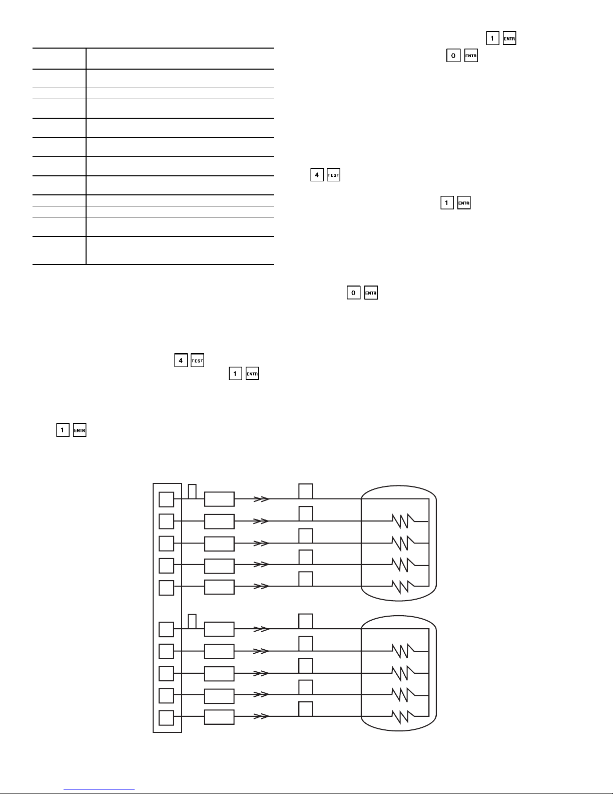
Table 35 — Illegal Configurations Recognized
by PSIO-1
CODE
NUMBER
ILLEGAL CONFIGURATION
DESCRIPTION
1
Incorrect Check Sum in configuration code
(factory or service code)
2 Unit type outside range of (1-3)
3
Number of compressors in a circuit outside the
range of 0-2
4
Air cooled chiller with a fan type outside the
range of 1-16
5
Air cooled chiller with Low Temperature Brine
fluid
6
Water cooled chiller configured for air cooled
head pressure
7
Selecting both OAT and Space Temp sensors
for External Reset operation
8 Air cooled chiller with condenser water pump
9 Air cooled chiller with condenser thermistors
10
MOP Set point is outside the range of
40 - 55 F (4.4 - 12.8 C)
11
Maximum Condensing Temperature Set point
(MCT_SP) is outside the range of 0 - 158 F
(-17.8 - 70 C)
LEGEND
MOP — Minimum Operating Temperature
OAT — Outdoor-Air Temperature
EXD Troubleshooting Procedure — Follow steps
below to diagnose and correct EXV/Economizer problems.
On 30HX units with economizers, verify that the valve
for the bubbler tube (bottom of economizer) is open. Check
EXV motor operation first. Press on the HSIO II
keypad and select the appropriate EXV. Press to
move the valve to 25%. You should be able to feel the ac-
tuator moving by placing your hand on the EXV or economizer body (the actuator is located about one-half to twothirds of the way up from the bottom of the economizer shell).
Press three more times until the display reads 100%
for a Target Percent (waiting until actuator stops each time).
A hard knocking should be felt from the actuator when
it reaches the top of its stroke (can be heard if
surroundings are relatively quiet). Press again if
necessary to confirm this. Press four times to step
the actuator closed in 25% increments, waiting again in be-
tween each move. The actuator should knock when it reaches
the bottom of its stroke. If it is believed that the valve is not
working properly, continue with the checkout procedure
below:
Check the EXV output signals at appropriate terminals
on EXV driver module (see Fig. 12). Connect positive test
lead to terminal 1 on the EXV driver for Circuit A and to
terminal 7 for Circuit B. Set meter for approximately 20 vdc.
Enter Valves and Motor Master test subfunction by pressing
on the HSIO. The EXV for Circuit A will be dis-
played; if desired, press the down arrow key for Circuit B.
When at the desired valve, press . The display should
change to show a Target Percent of 25%. The driver should
drive the circuit EXV under test. During the next several seconds, connect negative test lead to pins 2, 3, 4, and 5 in succession (pins 8, 9, 10 and 11 for Circuit B). Voltage should
rise and fall at each pin. If it remains constant at a voltage
or shows 0 volts, remove the connector to the valve and
recheck.
Press to close the circuit EXV. Check the DSIO
address setting (the address should be 50). If a problem still
exists, replace the EXV driver module. If the voltage reading is correct, the expansion valve and EXV wiring should
be checked. Check the EXV terminal strip and interconnecting wiring.
1. Checkcolorcodingand wire connections. Make sure they
are connected to the correct terminals at the EXV driver
and EXV plug and that the cables are not crossed.
2. Check for continuity and tight connection at all pin
terminals.
Check the resistance of the EXV motor windings.
Remove the DSIO-EXV plug J4 terminal strip and check the
resistance between the common lead (red wire, terminal D)
and remaining leads, A, B, C, and E (see Fig. 12). The resistance should be 25 ohms ± 2 ohms.
RED
GRN
WHT
BLK
BRN
D
C
E
B
A
RED
GRN
WHT
BLK
BRN
D
C
E
B
A
EXV-A
EXV-B
7
2
1
1
2
3
4
5
8
9
10
11
EXV DRIVER BOARD, J4
EXV — Electronic Expansion
Valve
Fig. 12 — EXV Cable Connections to EXV Driver Module, DSIO-EXV
50
Page 51
INSPECTING/OPENING ELECTRONIC EXPANSION
VALVES
IMPORTANT:ObtainreplacementO-ringbeforeopening EXV. Do not reuse O-rings.
To check the physical operation of an EXV, the following
steps must be performed:
1. Close the liquid lineservicevalveof the circuit to bechecked.
Put the LOR switch in the OFF position. Using the
HSIO, enter the manual service mode by pressing
. Enable the mode by pressing . Switch
the LOR switch to the Local position. Scroll down to the
desired compressor and press to turn it on. Let
compressor run until gage on suction pressure port reads
between 5 and 10 psig. Press to turn the com-
pressor off. Immediately after the compressor shuts off,
close the discharge valve.
2. Remove any remaining refrigerant from the system low
side using proper reclaiming techniques. Drain oil from
cooler using Schrader port in cooler inlet line. Turn off
the line voltage power supply to the compressors and control circuit power.
3. Remove screws holding top cover of EXV. Carefully remove the top cover from the EXV making sure EXV plug
is still connected.
IMPORTANT: When removing top cover from
EXVs, be careful to avoid damage to motor leads.
4. Entertheappropriate EXVtest step for EXV-A or EXV-B
by pressing on the HSIO. Scroll down to display
the desired EXV. Press and to initiate the test.
Observe the operation of the valve motor and lead screw.
The motor shouldturncounterclockwise,andthe lead screw
should move up out of the motor hub until the valve is
fully open. Lead screw movement should be smooth and
uniform from fully closed to fully open position. Press
as needed to reach 100% open. Wait 30 seconds
in between each step for motor to stop moving. Press
to check open to closed operation. If the valve is
properly connected to the processor and receiving correct
signals, yet does not operate as described above, the valve
should be replaced.
INSPECTING/OPENING ECONOMIZERS — To check the
physical operation of an economizer (see Fig. 13), the following steps must be performed:
1. Close the liquid lineservicevalveof the circuit to bechecked.
Put the LOR switch in the OFF position. Using the
HSIO, enter the manual service mode by pressing
. Enable the mode by pressing . Switch
the LOR switch to the Local position. Scroll down to the
desired compressor and press to turn it on. Let
compressor run until gage on suction pressure port reads
between 5 and 10 psig. Press to turn the com-
pressor off. Immediately after the compressor shuts off,
close the discharge valve and the bubbler valve on 30HX
units (located in elbow fitting on condenser shell).
2. Remove any remaining refrigerant from the system low
side and discharge piping using proper reclaiming techniques. For 30GX units, there is no shutoff valve in the
bubbler tube line. Drain oil from cooler using Schrader
port in cooler inlet line. Turn off the line voltage power
supply to the compressors and control circuit power.
3. Remove the shell retaining bolts on the bottomoftheeconomizer and the bolts that secure the shell to the unit frame
or mounting bracket. Cut the motor cooling line leaving
the top of the economizer.Carefullyremovetheshellfrom
the economizer. Make sure EXV plug is still connected.
IMPORTANT: When removing shell from economizer, it must be lifted off as close to vertical as
possible to prevent damage to any of the internal
parts. Use a catch pan beneath the economizer as
oil will come out when the shell is removed. Be
careful to avoid damage to motor leads.
4. Entertheappropriate EXVtest step for EXV-A or EXV-B
by pressing on the HSIO. Scroll down to display
the desired EXV. Press and to initiate the test.
Observe the operation of the valve motor and lead screw.
The motor shouldturncounterclockwise,andthe lead screw
should move up out of the motor hub until the valve is
fully open. Lead screw movement should be smooth and
uniform from fully closed to fully open position. Press
as needed to reach 100% open. Wait 30 seconds
in between each step for motor to stop moving. Press
to check open to closed operation. If the valve is
properly connected to the processor and receiving correct
signals, yet does not operate as describedabove,theeconomizer should be replaced.
5. Additional items to check for:
a. Verify that float assembly (see cross section view in
Fig. 13) moves up and down freely. It should take only
a minimal force (less than one pound) to move the float
and there should be no binding.
b. Check the bubbler tube (found by carefully lifting the
float) for crimps, etc. and verify that the end of the
tube is open.
6. Reassemble economizer; retorque shell retaining bolts to
35 ft-lb (48 N-m).
If operating problems persist after reassembly, they may
be due to a bad liquid level sensor, suction pressure transducer or intermittent connections between the processor board
terminals and EXV plug. Recheck all wiring connections and
voltage signals.
Other possible causes of improper refrigerant flow control could be restrictions in the liquid line. Check for plugged
strainer(s) or restricted metering slots in the EXV or economizer. Formation of ice or frost on lower body of electronic
expansion valve is one symptom of restricted metering slots.
However, frost or ice formation is normally expected when
leaving fluid temperature from the cooler is below 40 F. Clean
or replace valve if necessary.
NOTE (non-economizer units only): Frosting of valve is normal during compressor test steps and at initial start-up. Frost
should dissipate after 5 to 10 minutes operation in a system
that is operating properly. If valve is to be replaced, wrap
valve with a wet cloth to prevent excessive heat from damaging internal components.
51
Page 52
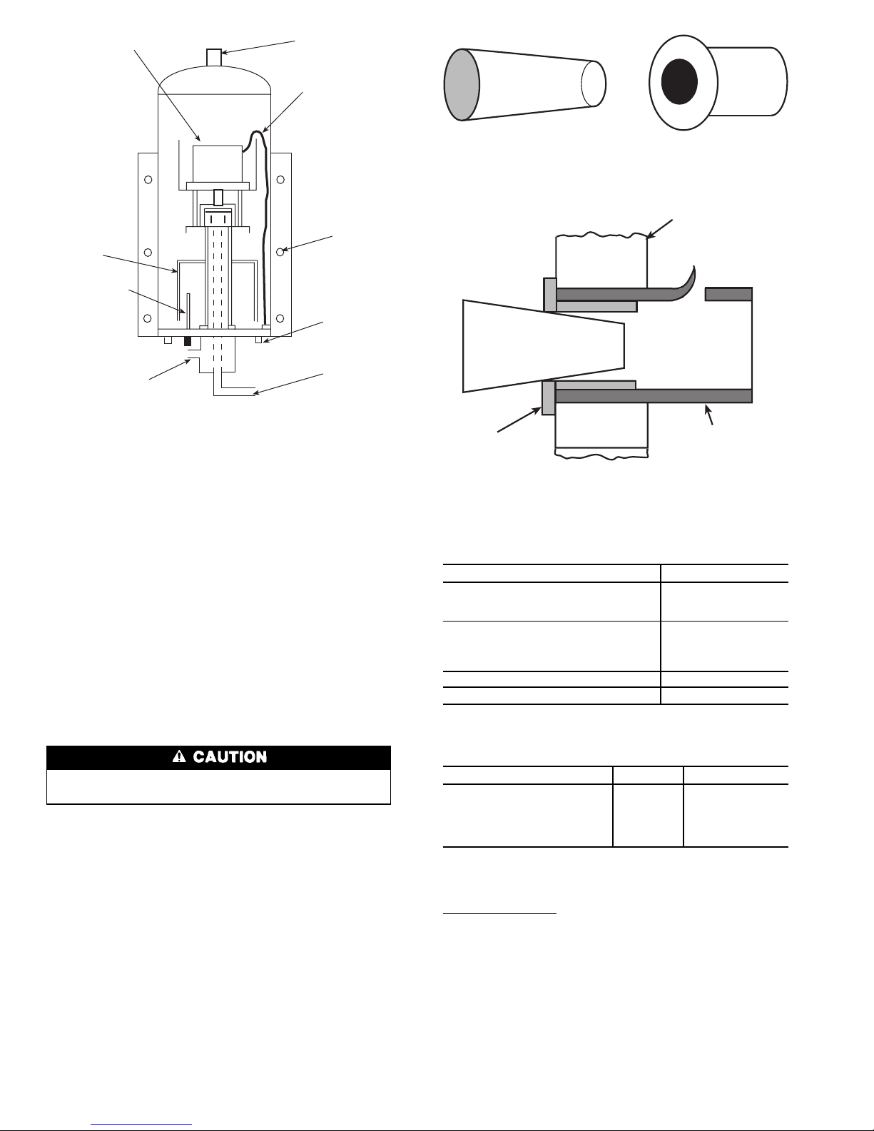
SERVICE
ServicingCoolersandCondensers—
When cooler
heads and partition plates are removed, tube sheets are exposed showing the ends of tubes. The 30GX,HX units use a
flooded cooler design. Water flows inside the tubes.
TUBE PLUGGING — A leaky tube can be plugged until
retubing can be done. The number of tubes plugged determines how soon the cooler must be retubed. All tubes in the
30GX and 30HX coolers and 30HX condensers can be removed. Loss of unit capacity and efficiency as well as increased pump power will result from plugging tubes. Failed
tubes should be replaced as soon as possible. Up to 10% of
the total number of tubes can be plugged before retubing is
necessary. Figure 14 shows an Elliot tube plug and a crosssectional view of a plug in place. The same components for
plugging and rolling tubes can be used for all coolers and
30HXC condensers. See Table 36.
Use extreme care when installing plugs to prevent damage to the tube sheet section between the holes.
RETUBING (See Table 37) — When retubing is to be done,
obtain service of qualified personnel experienced in boiler
maintenance and repair.Moststandardprocedurescanbefollowed when retubing the 30GX and 30HX heat exchangers.
A7%crushisrecommended when rolling replacement tubes
into the tubesheet. A 7% crush can be achieved by setting
the torque on the gun at 48 to 50 in.-lb (5.4 to 5.6 N-m).
The following Elliot Co. tube rolling tools are required:
B3400 Expander Assembly
B3401 Cage
B3405 Mandrel
B3408 Rolls
Place one drop of Loctite No. 675 or equivalent on top of
tube prior to rolling. This material is intended to ‘‘wick’’ into
the area of the tube that is not rolled into the tube sheet, and
prevent fluid from accumulating between the tube and the
tube sheet. New tubes must also be rolled into the center
tube sheet to prevent circuit-to-circuit refrigerant leakage.
Table 36 — Plugging Components
COMPONENTS FOR PLUGGING PART NUMBER
For Tubes
Brass Pin 853103-1A*
Brass Ring 853002-640*
For Holes without Tubes
Brass Pin 853103-1A*
Brass Ring 853002-738*
Roller Extension S82-112/11
Loctite No. 675†
Locquic ‘‘N’’†
*Order directly from: Elliot Tube Company, Dayton, Ohio.
†Can be obtained locally.
Table 37 — Tube Diameters
ITEM INCHES MILLIMETERS
Tube sheet hole diameter: 0.756 19.20
Tube OD 0.750 19.05
Tube ID after rolling:
(includes expansion
due to clearance)
0.704
to
0.710
17.88
to
18.03
NOTE: Tubes replaced along heat exchanger head partitions must
be flush with tube sheet.
TIGHTENING COOLER/CONDENSER HEAD BOLTS
O-Ring Preparation — When reassembling cooler and con-
denser heads, always check the condition of the O-ring(s)
first. The O-ring should be replaced if there are any visible
signs of deterioration, cuts or damage. Apply a thin film of
grease to the O-ring before installation. This will aid in holding the O-ring into the groove while the head is installed.
Torque all bolts to the following specification and in the
sequence shown in Fig. 15.
3
⁄4-in. Diameter Perimeter and
Plate Bolts ........................200to225ft-lb.
(271 to 305 N-m)
SHELL BOLTS
OUTLET FOR
MOTOR COOLING
LINE CONNECTION
STEPPER MOTOR
HARNESS
MOUNTING
BRACKET
BOLTS
STEPPER MOTOR
FLOAT
ASSEMBLY
DISCHARGE GAS
BUBBLER TUBE
OUTLET TO BOTTOM
OF COOLER
LIQUID INLET
TUBE FROM
CONDENSER
Fig. 13 — 30GX,HX Cutaway View of
Economizer Assembly
PIN AND RING INSTALLED
TUBE SHEET
PIN
TUBE
RING
PIN
RING
Fig. 14 — Tube Plugging
52
Page 53
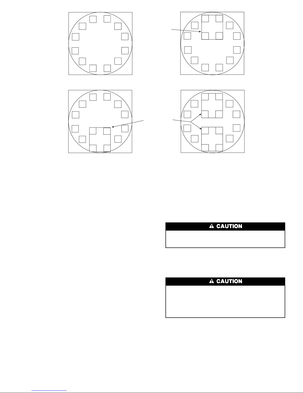
1. Install all bolts finger tight.
2. Follow numbered sequence shown for head type being
installed. This will apply even pressure to the O-ring.
3. Apply torque in one-third steps until required torque is
reached. Load all bolts to each one-third step before proceeding to the next one-third step.
4. No less than one hour later, retighten all bolts to required
torque values.
5. Restore water/brine flow and check for leaks. Fix leaks
as necessary. Replace insulation (on cooler heads only).
Inspecting/Cleaning Heat Exchangers
COOLERS — Inspect and clean the cooler tubes at the end
of the first operating season. Because these tubes have internal ridges, a rotary-type tube cleaning system is necessary to fully clean the tubes. Tube condition in the cooler
will determine the scheduled frequency for cleaning, and will
indicate whether water treatment is adequate in the chilled
water/brine circuit. Inspect the entering and leaving thermistors for signs of corrosion or scale. Replace the sensor if
corroded or remove any scale if found.
CONDENSERS (30HX Only) — Since this water circuit is
usually an open-type system, the tubes may be subject to
contamination and scale. Clean the condenser tubes with a
rotary tube cleaning system at regular intervals, and more
often if the water is contaminated. Inspect the entering and
leaving condenser water thermistors (if installed) for signs
of corrosion or scale. Replace the sensor if corroded or remove any scale if found.
Higher than normal condenser pressures, together with inability to reach full refrigeration load, usually indicate dirty
tubes or air in the machine. If the refrigeration log indicates
a rise above normal condenser pressures, check the condenser refrigerant temperature against the leaving condenser
water temperature. If this reading is more than what the design difference is supposed to be, then the condenser tubes
may be dirty, or water flow may be incorrect. Due to the
pressure in the R-134a system, air usually will not enter the
machine; the refrigerant will leak out.
During the tube cleaning process, use brushes specially
designed to avoid scraping and scratching the tube wall. Contact your Carrier representative to obtain these brushes. Do
not use wire brushes.
Hard scale may require chemical treatment for its prevention or removal. Consult a water treatment specialist
for proper treatment procedures.
Water Treatment — Untreated or improperly treated
water may result in corrosion, scaling, erosion, or algae. The
services of a qualified water treatment specialist should be
obtained to develop and monitor a treatment program.
Water must be within designflowlimits,cleanandtreated
to ensure proper machine performance and reduce the
potential of tubing damage due to corrosion, scaling, erosion, and algae. Carrier assumes no responsibility for
chiller or condenser damage resulting from untreated or
improperly treated water.
Condenser Coils (30GX Only)
COIL CLEANING — Clean coils with a vacuum cleaner,
fresh water,compressedair, or a bristle brush (not wire). Units
installed in corrosive environments should have coil cleaning as part of a planned maintenance schedule. In this type
of application, all accumulations of dirt should be cleaned
off the coil.
2
5
9
11
6
3
1
8
14
13
7
4
10
12
11
9
5
2
4
7
3
1
8
13
15
14
16
10
12
6
9
5
2
4
7
12
14
11
13
8
1
3
6
10
BLANK PLATE
BLANK PLATES
9
5
2
4
7
11
12
8
1
3
6
10
Fig. 15 — Cooler and Condenser Head Recommended Bolt Torque Sequence
53
Page 54
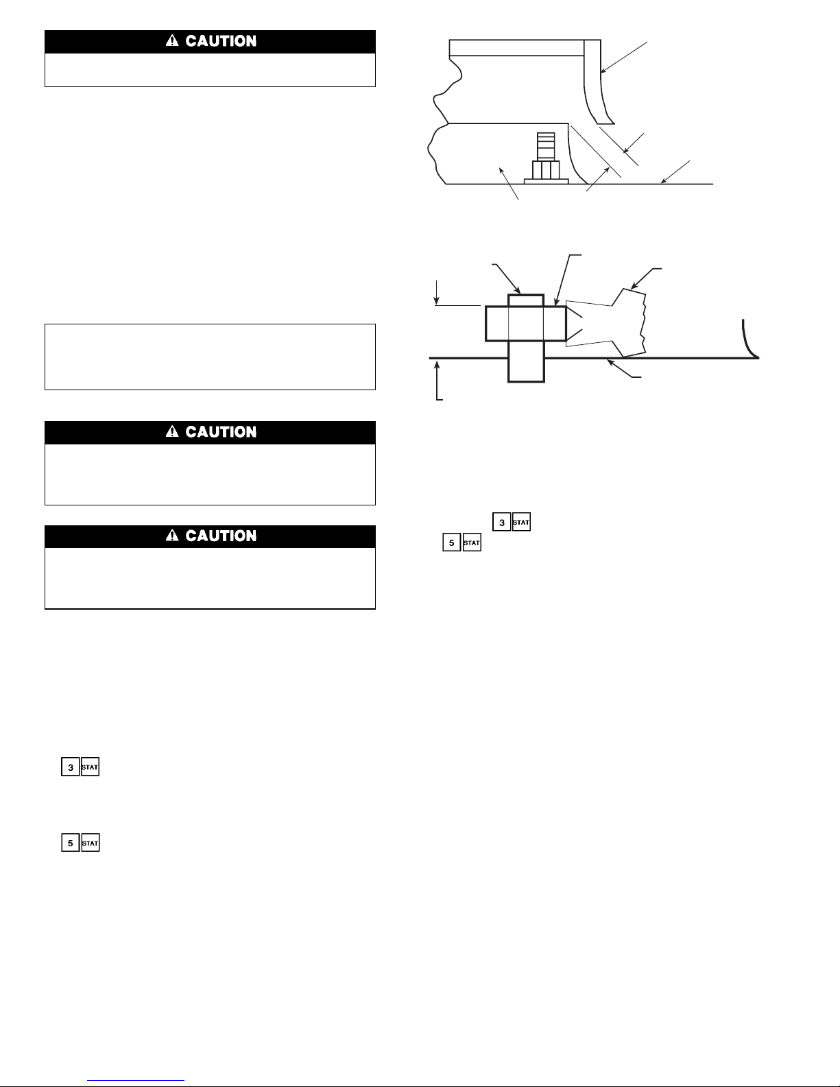
Do not use high-pressure water or air to clean coils as
fin damage may result.
Condenser Fans (30GX Only) — Each fan is sup-
ported by a formed wire mount bolted to a fan deck and
covered with a wire guard. The exposed end of the fan
motor shaft is protected from weather by grease. If the fan
motor must be removed for service or replacement, be sure
to regrease fan shaft and reinstall fan cover, retaining clips,
and fan guard. For proper performance, the fans should be
positioned as shown in Fig. 16 or 17. Tighten setscrews to
14 ± 1 ft-lb (18 ± 1.3 N-m).
Check for proper rotation of the fan(s) once reinstalled
(clockwise for high static and counterclockwise for standard
viewed from above). If necessary to reverse, switch leads at
contactor(s) in control box.
Refrigerant Charging/Adding Charge
IMPORTANT: These units are designed for use with
R-134a only. DO NOT USE ANY OTHER REFRIGERANT in these units without first consulting your
Carrier representative.
When adding or removing charge,circulatewaterthrough
the condenser (30HXC) and cooler at all times to prevent freezing. Freezing damage is considered abuse and
may void the Carrier warranty.
DO NOT OVERCHARGE system. Overcharging results in higher discharge pressure with higher cooling
fluid consumption,possiblecompressordamageand higher
power consumption.
Indication of low charge on a 30HXC system:
NOTE: To check for low refrigerant charge on a 30HXC,
several factors must be considered.A flashing liquid-line sight
glass is not necessarily an indication of inadequate charge.
There are many system conditions where a flashing sightglass
occurs under normal operation. The 30HXC metering device is designed to work properly under these conditions.
1. Make sure that the circuit is running at a full-load con-
dition. To check whether circuit A is fully loaded, enter
on the HSIO keypad. The display will read
‘‘CIRCUIT AANALOG VALUES.’’Using the down arrow key on the keypad, scroll down once to ‘‘Total
Capacity.’’Ifthisvalue is 100%, the circuit is at full load.
To check circuit B, follow the same procedure, but enter
on the keypad.
2. It may be necessary to use the Manual Control feature to
force the circuit into a full-load condition. If this is the
case, see the instructions for using the Manual Control
feature in Table 19 of this manual.
3. With the circuit running at full load, verify that the cooler
leaving fluid temperature is in the range of 38 to 46 F
(3.3 to7.8C).Checkpressure drop across liquid line strainer
and replace strainer if necessary.
4. Atthis condition, observe the refrigerant in the liquid line
sight glass. If there is a clear sight glass, and no signs of
flashing, then the circuit is adequately charged. Skip the
remaining steps.
5. Iftherefrigerantappearstobe flashing, the circuit is probably low on charge. Verify this by checking the EXV
Percent Open. This information can be accessed by
entering on the HSIO keypad for Circuit A, or
for Circuit B. Scroll down using the down arrow
key on the keypad, until EXV Percent Open is displayed.
6. If the EXV Percent Open is greater than 60%, and the
liquid-line sight glass is flashing, then the circuit is low
on charge. Follow the procedure for adding charge for
30HXC units.
To add charge to the 30HXC systems:
1. Make sure that the unit is running at full load, and that
the cooler leaving fluid temperature is in the range of 42
to 46 F (5.6 to 7.8 C).
2. At these operating conditions, check the liquid line sight
glass. If there is a clear sight glass, then the unit has sufficient charge. If the sight glass is flashing, then check the
EXV Percent Open. If this is greater than 60%, then begin adding charge.
NOTE:Aflashing liquid line sight glass at operating conditions other than those mentioned above is not necessarily an indication of low refrigerant charge.
3. Add 5 lb of liquid charge into the cooler using the
1
⁄4-in.
Schrader-type fitting located on the tube entering the bottom of the cooler.Thisfittingislocated between the Electronic Expansion Valve (EXV) (size 076-146 units), or
the economizer (size 161-271 units) and the cooler.
4. Observe the EXV Percent Open value. The EXV should
begin closing as charge is being added. Allow the unit to
stabilize. If the EXV Percent Open remains above 60%,
and the sight glass continues flashing, add an additional
5 lb of liquid charge.
5. Allow the unit to stabilize, and again check the EXV Percent Open. Continue adding 5 lb at a time of liquid refrigerant charge, and allow the unit to stabilize before
checking the EXV position.
PLASTIC FAN
PROPELLER
CLEARANCE OF 0.25 INCHES
(6.4 MM) FOR STANDARD
CONDENSER FANS
FAN DECK
SURFACE
FAN ORIFICE
Fig. 16 — Condenser Fan Position (Standard Fan)
POSITION TOP OF HIGH STATIC FAN PROPELLER HUB
2.15 INCHES (54.6 mm) ABOVE FAN DECK SURFACE
FAN DECK
SURFACE
STATIC FAN
PROPELLER
FAN HUB
2.15 IN.
MOTOR
SHAFT
Fig. 17 — Condenser Fan Position (High Static Fan)
54
Page 55
6. WhentheEXVPercentOpenisintherangeof 40 to 60%,
check the liquid line sight glass. Slowly add enough additional liquid charge to ensure a clear sight glass. This
should be done slowly to avoid over-charging the unit.
7. Verify adequate charge by continuing to run at full load
with 42 to 46 F (5.6 to 7.8 C) cooler leaving fluid temperature. Check that the refrigerant is not flashing in the
liquid-line sight glass. The EXV Percent Open should be
between 40 and 60%. The cooler level indicator should
be in the range of 1.5 to 2.2.
Indication of low charge on a 30HXA, GX systems:
1. Make sure that the circuit is running at a full load condition and all condenser fans are energized and running
at full speed. To check whether circuit A is fully loaded,
enter on the HSIO keypad. The display will read
‘‘CIRCUIT AANALOG VALUES.’’Using the down ar-
row key on the keypad, scroll down once to ‘‘Total
Capacity.’’Ifthisvalue is 100%, the circuit is at full load.
To check circuit B, follow the same procedure, but enter
on the keypad.
2. It may be necessary to use the Manual Control feature to
force the circuit into a full-load condition. If this is the
case, see the instructions for using the Manual Control
feature in Table 19 on page 31 of this manual.
3. With the circuit running at full-load, verify that the cooler
leaving fluid temperature is in the range of 38 to 48 F
(5.6 to 7.8 C).
4. For 30HXA chillers, raise the compressor discharge to
approximately 125 F (51.7 C) saturated discharge temperature (185 psig [1276 kPa]). For 30GX chillers, raise
the compressor discharge to approximately 130 F
(54.4 C) saturated discharge temperature (198 psig
[1366 kPa]). Measure the liquid temperature entering the
expansion device for 30HXAunits. For 30GX units, measure the liquid temperature after the tee where all liquid
lines have joined. The liquid temperature should be approximately 107 F (41.7 C) for optimum charge. If the
temperature is greater than 107 F (41.7 C) and the sight
glass is flashing, the circuit is undercharged.
5. Add 5 lb of liquid charge into the cooler using the
1
⁄4-in.
Schrader-type fitting located on the tube entering the bottom of the cooler.Thisfittingislocated between the Electronic Expansion Valve (EXV) (30HXA076-146 units,
30GX080-090 units), or the economizer (30HXA161271 units, 30GX105-176 units) and the cooler.
6. Allow the system to stabilize and then recheck the liquid
temperature. Repeat Step 5 as needed allowing the system to stabilize between each charge addition. Slowly add
charge as the sight glass begins to clear to avoid
overcharging.
Oil Charging/Low Oil Recharging
Addition of oil charge to 30HX,GX systems:
1. If the 30HX,GX unit shuts off repeatedly on Low Oil
Level (Alert number 71 or 72), this may be an indication of inadequate oil charge. It could also mean simply
that oil is in the process of being reclaimed from the
low-side of the system.
2. Begin by running the unit at full load for 1
1
⁄2hours. Use
the Manual Control feature of the software if the unit
does not normally run at full load.
3. After running the unit for 1
1
⁄2hours, allow the unit to
restart and run normally. If the Low Oil Level alarms
persist, continue following this procedure.
4. Close the liquid line service valve, and place a pressure
gage on top of the cooler. Enable the manual control
feature using the HSIO keypad, and turn the LOR switch
to local. Start the desired compressor by pressing
on the keypad, at the appropriate line on the
display.
5. Before starting the compressor, the unit will go through
its normal pre-lube pump routine. If there is an insufficient level of oil in the oil separator, the compressor
will not start, and a pre-start oil pressure alarm will be
posted. Skip to Step 8.
6. If the compressor starts successfully, observe the cooler
pressure gage. When this gage reads approximately
10 psig, press on the HSIO keypad, and move
the LOR switch to the off position.
7. Open the liquid line service valve and allow the unit to
restart and run normally. If the Low Oil Level alarms
persist, continue following this procedure.
8. If none of the previous steps were successful, the unit is
low on oil charge. Add oil to the oil separator using the
1
⁄4-in. Schrader-type fitting on the discharge line entering the top of the oil separator (30HX units) or through
the Schrader fitting on the top of the oil separator (30GX
units).
Do not add oil at any other location as improper
unit operation may result.
9. Make sure that the unit is not running when adding oil,
as this will make the oil charging process easier. Because the system is under pressure even when the unit
is not running, it will be necessary to use a suitable pump
(hand pump or electric pump) to add oil to the system.
10. Using a suitable pump, add
1
⁄2gal. (1.89 L) of Castrol
Icematict SW-220 Polyolester oil (Carrier Specification number is PP47-32; absolutely no substitutes are
approved) to the system. Make sure that the oil level
safety switch is NOT jumpered, and allow the unit to
restart and run normally. Do not exceed maximum oil
change. See Table 38.
11. If low oil level problems persist, add another 1.89 L
(
1
⁄2gal.) of oil. Continue adding oil in 1.89 L (1⁄2gal.)
increments until the problem is resolved. If it is necessary to add more than 5.75 L (1.5 gallons) of oil to the
system, contact your Carrier distributor service
department.
Table 38 — Maximum Oil Charges
UNIT
SIZE
CIRCUIT A
(gal)
CIRCUIT A
(L)
CIRCUIT B
(gal)
CIRCUIT B
(L)
30GX080-176 5.0 18.9 5.0 18.9
30GX205-265 7.0 26.5 5.0 18.9
30HXA076-186 5.0 18.9 5.0 18.9
30HXC076-186 4.5 17.0 4.5 17.0
30HXC206-271 7.5 28.4 5.0 18.9
55
Page 56
OilFilter Maintenance — Each compressor has its own
internal oil filter and each circuit also has an in-line external
filter. The internal oil filter pressure drop should be checked
and filter changed (if necessary) after the initial 200-300hours
of compressor operation. It is recommended that oil line pressure loss checks be made on an annual basis thereafter to
determine the need for filter changes.Theneedforfiltermaintenance can be monitored through system pressure drop. Discharge pressure is read at the oil separator and oil pressure
is read at the compressor. This pressure differential is typically 15 to 20 psi (103 to 138 kPa) for a system with clean
internal and external filters. See Pressure Transducers section, page 59 for information on removing discharge pressure transducers to measure discharge pressure. Figure 18
shows the location of the oil pressure bleed port on the compressor.A gage can be attached to this point so that two pressure drops can be measured.Thedifference between discharge
pressure and the gage pressure will be the pressure loss due
mainly to the external oil filter. If this value exceeds 10 psi
(69 kPa), replace the external filter. The difference between
the gage pressure and compressor oil pressure is the pressure drop through the internal oil filter. Replace the internal
oil filter if the pressure drop is greater than 30 psi (207 kPa).
REPLACING THE EXTERNAL OIL FILTER
Compressor oil is pressurized. Use proper safety precautions when relieving pressure.
Fully front seat (close) the angle valve on the filter. Connect
a charging hose to the oil pressure bleed port and drain the
oil trapped between the filter and the internal check valve.
Use the function to cycle the oil solenoid a few times
to properly seat the internal check valve as the pressure is
being relieved. If the oil pressure does not bleed off using
this method it will be necessary to remove the entire circuit
charge.Apint of oil is typically what is removed during this
process. Remove the charging hose.
Unscrew the nut from the other side of the filter and remove
the old filter. Remove protective plastic caps from new filter
and install. Draw a vacuum at the bleed port. Remove charging hose. Open angle valve enough to let oil flow. Check
both fittings for leaks and repair if necessary.Backseat angle
valve.
REPLACING THE INTERNALOILFILTER — Follow the
procedure above to the point that the oil has been drained
from the bleed port. Using a
3
⁄4-in. allen wrench, remove the
internal filter access cover (see Fig. 18). Remove the old filter. Replacement filters (one for each compressor) are factory supplied to cover the first changeout. After that, filters
are field supplied. Remove the old O-ring from internal check
valve. Lightly oil O-ring and install into groove. Install new
filter open end first into the housing. Replace access cover
and retorque to 150 ft-lb (203 N-m). Follow procedure in
previous section for opening angle valve and purging lines.
Check for leaks and repair if necessary.
Compressor Changeout Sequence
NOTE: Replacement compressors can be ordered by calling
800-CARLYLE (800-227-5953). In most cases, replacement compressors can be shipped in 1 to 2 business days.
Compressor service requires metric tools and hardware.
Change compressors according to the following procedure:
1. Turn off all main and control circuit power supplying
the machine.
2. Close the discharge and liquid valve(s), suction valve,
and cooler inlet line service valve (if equipped), oil line
shutoff valve, economizer bubble tube valve
(30HXA,C161-271 only) andminimumloadshutoff valve
(if equipped) for circuit to be changed. Disconnect the
oil inlet line from the compressor. Disconnect oil filter
with fitting at shutoff valve side and set filter and compressor inlet line assembly aside.
3. Removeanyremainingrefrigerantinthecompressorand
refrigerant lines using proper reclaiming techniques.All
of the refrigerant that is in the cooler must be removed
if there is no suction service valve installed on the cooler.
IMPORTANT: Cooler and condenser pumps must
be energized. Fluid must be flowing through heat
exchangers whenever adding or removing charge.
4. Removejunctionboxcoverofcompressortobechanged.
Check main power leads for marked numbers. If no numbers are visible on leads, mark leads with appropriate
numbers to match those printed on the ends of the terminal lugs. This is extremely important as powerleads
MUST be installed on the exact terminals fromwhich
they were removed.
5. Disconnectmain power leads from compressor terminal
lugs. Mark remaining control circuit wires (connected
together with wire nuts) for ease of reconnecting later.
The following color scheme applies (verify with label
diagram on panel):
Loader 1 2 Violet wires
Loader 2 2 Pink wires
Motor Cooling Solenoid 1 Blue wire, 1 Brown wire *
Oil Solenoid 1 Orange wire, 1 Brownwire*
High-Pressure Switch 2 Red wires
*One lead from the motor cooling and oil solenoids are con-
nected together with a single brown wire.
6. Remove loader (mark solenoids no. 1 and 2 for replacement) and oil solenoids and high-pressure switch from
compressor. Using 2 wrenches, carefully remove the oil
pressure transducer from the compressor. These will all
be reconnected to the replacement compressor.
NOTE: Some oil will leak out of the transducer fitting
when the transducer is removed. See Fig. 18.
7. Mark motor temperature leads (2 blue wires) and remove from quick connect terminals in the junction box.
The next steps involve compressor unbolting and
removal. Compressor seals are made using O-rings.
Use care when removing bolts and disconnecting
flanges. The O-rings must NOT be re-used. New
O-rings are provided with the replacement compressor. The 06N screw compressors weigh ap-
proximately 900 pounds. Be sure that an appropriate lifting cart or hoist is used to avoid injury.
See Fig. 19 for lifting locations and center of gravity dimensions. Make sure compressor is properly
rigged before unbolting.
8. Remove the 2 bolts securing the motorcooling/economizer
line flange to the compressor.
56
Page 57
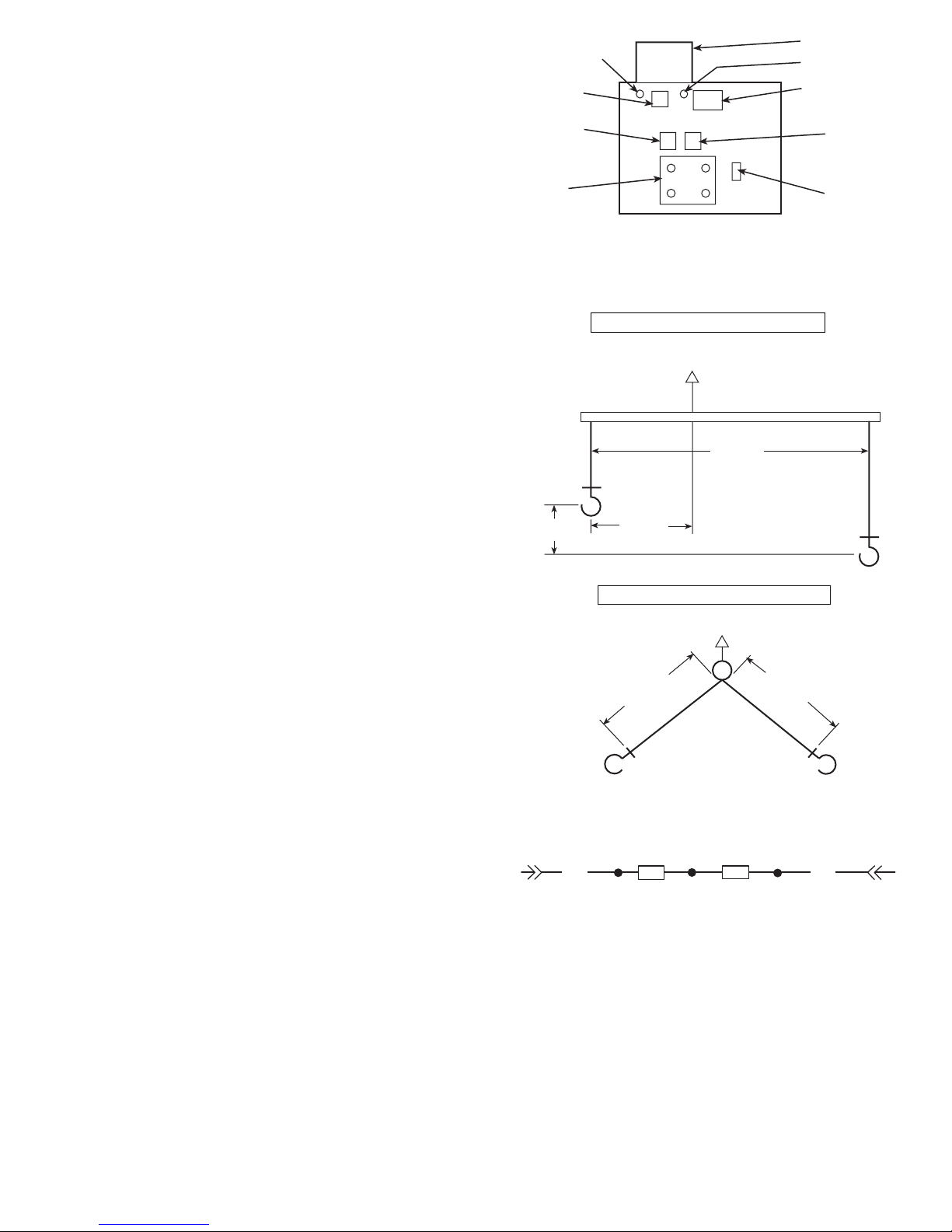
9. Remove the four M14 bolts securing the discharge line
flange to the compressor. Two of the bolts also secure
the mounting bracket for the external oil filter. Support
the oil line to prevent damage to the line while the compressor is being changed. For 30GX units, place temporary protectionovercoilstoprevent fin and tube damage.
10. Movelifting apparatus into place and attach to the 2 lifting rings on the compressor. Apply minimal tension to
hold the compressor while the remaining bolts are
removed.
11. Remove the
3
⁄8-in. holddown bolt securing the foot at
the dischargeendof the compressor to themountingbracket
on the cooler.A foot bracket will be mounted to the replacement compressor.
12. Remove the 4 lockwashers and nuts securing the compressor to the suction flange of the cooler. The compressor is held in place using four M14 x 2 studs through
the suction nozzle of the cooler. The studs have an E-12
external Torx drive head. If possible, remove studs; if
studs hit the cooler insulation, leave them in place —
they will not interfere with compressor removal or installation. Save all the hardware as it will be needed to
install the replacement compressor.
13. After checking to ensure all lines, wires, conduits, etc.
are free and out of the way, remove compressor from
cooler.Apply a light film of O-ring grease to new O-ring
and place back into groove in mounting flange of compressor. If the new compressor is the A1 or A2 (30HX
units) compressor, remove the compressor junction box
and rotate it 180 degrees. Tighten screws to 6.8 to
9.5 N-m (5 to 7 ft-lb). The A1 and A2 compressors are
on the right side of the unit when facing the unit control
box.
14. Remove suction cover plate and bolts from new compressor and set compressor on unit flange. Thread the
studs all the way back into the compressor. Install
the 4 lockwashers and nuts finger-tight. Tighten bolts
in a crossing pattern to a range of 81.4 to 135.6 N-m
(60 to 100 ft-lb). Do NOT overtighten as damage may
result to O-ring. Install and tighten hold down bolt in
mounting foot.
15. Remove motor cooling/economizer and discharge line
cover plates from new compressor.
16. Apply a light film of O-ring grease to motor cooling/
economizer and discharge line O-rings, place back into
grooves and install flange bolts. Tighten discharge line
bolts in a crossing pattern to a range of 81.4 to
135.6 N-m (60 to 100 ft-lb). Tighten motor cooling/
economizer bolts to a range of 81.4 to 108.5 N-m (60 to
80 ft-lb). Do NOT overtighten as damage may result to
O-rings.
17. Reconnect the oil filter to the shutoff valve and oil line
to the compressor. Install oil line straight into fitting until ferrule seats against fitting. Thread packing nut onto
fitting and tighten finger tight. Use a backup wrench to
finish tightening the nut. Do not overtighten.
18. Reinstall the loader and oil solenoids, high-pressureswitch,
and oil pressure transducer. Make sure the loader solenoids are installed on the correct number loader.
19. Reconnect conduits back into compressor junction box.
Reconnect all wiring that was removed in Steps 4, 5,
and 7. The replacement compressor comes with a reverse rotation switch. This switch must be wired in series with the high-pressure switch for compressor protection. Reconnect these wires as shown in Fig. 20.
20. Leak check compressor and refrigerant lines with nitrogen. Repair any leaks found. Remove nitrogen from system. Evacuate compressor and refrigerant lines. Refer
to the Refrigerant and Oil Charging sections on
pages 54 and 55 for recharging procedures.
21. Open all shutoff valves and leak check the circuit and
all fittings and joints. Repair any leaks found.
JUNCTION BOX
OIL BLEED PORT
HIGH
PRESSURE
SWITCH
LOADER
SOLENOID
NO. 1
INTERNAL OIL
FILTER ACCESS
(3/4 in.)
OIL PRESSURE
TRANSDUCER
OIL
SOLENOID
LOADER
SOLENOID
NO. 2
LOADER
COVER
PLATE
Fig. 18 — Transducer Removal
DISCHARGE END
GEAR COVER END
CENTER OF GRAVITY
OF COMPRESSOR
508 mm
(20.0 in.)
178 mm
(7.0 in.)
95 mm
(3.75 in.)
CENTER OF GRAVITY
OF COMPRESSOR
DISCHARGE END
GEAR COVER END
MINIMUM
381 mm
(15 in.)
MINIMUM
381 mm
(15 in.)
COMPRESSOR LIFTING MECHANISM
NOTE: Locatestrapfrom center ofgravitylifting ring andsupportmotor casing to provide 3-point level rigging.
Fig. 19 — Compressor Lifting Diagrams
COMPRESSOR LIFTING MECHANISM
ONE LUG AT OUTSIDE EDGE, RING AT
DISCHARGE CENTER
LIFTING LUGS BOTH OUTSIDE EDGES
RED
PL1-5
HPS
RRS
RED
PL1-6
LEGEND
HPS — High-Pressure Switch
PL — Plug
RRS — Reverse Rotation Switch
Fig. 20 — High-Pressure Switch Wiring
57
Page 58
22. Restore main and control power to the machine. Using
the HSIO, enter the quick test function by pressing
(for compressor A1 or A2 replacement) or
(for compressor B1 replacement). Test the op-
eration of the solenoids. Press totesteachloader
solenoid, then use the key to find the motor cool-
ing and oil solenoids and test them in the same manner.
Pressing the key after each output turns the
solenoid off (or press ). It is important that the
loaders are located properly (loader 1 on right hand side
when viewed from side opposite control box on 30HX
units, on left hand side when reaching over compressor
to far side on 30GX units).
23. Start the compressor using the Manual mode. Press
at the HSIO.Press to enable the Manual
mode. When display changes to ‘‘Enable,’’ switch the
Local-Off-Remote switch to the Local position. Select
the desired compressor using the down arrow key. Press
to start the compressor. Use the down arrow
key and press to energize both loaders. Let the
circuit stabilize with both loaders energized. Refer to the
Refrigerant and Oil Charging sections of this document
for recharging procedures and performance criteria.
BURNOUT CLEANUP PROCEDURE — If a screw compressor motorburnsouton a 30GX,HX chiller,asimplecleanup
should be performed. The following procedure provides the
minimum steps to be taken before restarting the circuit.
1. Remove the oil from the oil separator. This can be facilitated by connecting a hose to the port located on the
service valve entering the external oil filter.Run the hose
to a container(s) that can hold up to 5 to 6 gallons of oil.
To force out most of the oil in the separator pressurize
the circuit. To remove the remaining oil, the pre-lube
pump can be run in mode from the HSIO. To prevent wear to the gears, do not allow the pre-lube pump
to operate ‘‘dry.’’
2. Remove the failed compressor following the Compressor Changeout Sequence procedure above.
3. Oncethecompressoris removed access the oil catch pan
through the cooler-compressor mounting flange. Clean
out any debris which may have collected in the oil catch
pan.
4. Install a new compressor.
5. To dilute and remove any residual oil left in the separator, pump approximately
1
⁄2gallon of compressor oil
into the oil separator using the Schrader port located on
top oftheseparator(30GX) or on the dischargeline(30HX)
and remove using the pre-lube pump described in
Step 1.
6. Disconnect the hose from the external oil filter service
valve.
7. Install a new filter drier and compressor external oil
filter.
8. Measure in the amount of Castrol SW 220 Polyolester
oil as specified on the nameplate of the chiller.
9. Leak check, evacuate and recharge the machine as described in this manual with the amount of R-134a stated
on the chiller nameplate.
10. Perform periodic acid checks on the circuit and change
the filter drier in the motor cooling line as necessary.
Use the Carrier Standard Service Techniques Manual as
a source of reference.
Moisture-Liquid Indicator — Clear flow of liquid
refrigerant indicates sufficient charge in the system. Note,
however, that bubbles in the sight glass do not necessarily
indicate insufficient charge. Moisture in the system
is measured in parts per million (ppm), changes of color of
indicator are:
Green — moisture is below 80 ppm;
Yellow-green (chartreuse) — 80 to 225 ppm (caution);
Yellow (wet) — above 225 ppm.
Change filter drier at the first sign of moisture in the
system.
IMPORTANT: Unit must in operation for at least
12 hours before moisture indicator can give an accurate reading. With the unit running, the indicating element must be in contact with liquid refrigerant to give
true reading.
Filter Drier — Whenever moisture-liquid indicator shows
presence of moisture, replace filter drier. Refer to Carrier
Standards Service Technique Manual, Chapter 1, Refrigerants, for details on servicing filter driers.
Liquid Line Service Valve — This valve is located
ahead of the filter drier and provides a1⁄4-in. Schrader connection (30GX only) for field charging. In combination with
compressor dischargeservicevalve,each circuit can be pumped
down into the high side for servicing.
Thermistors — To aid in verifying thermistor perfor-
mance, resistances at various temperatures are listed for all
thermistors (except motor thermistors) inTables 39Aand39B.
See Table 40 for motor thermistor values.
LOCATION — General location of thermistor sensors and
terminal connections in the control box are listed in Table 2.
THERMISTOR REPLACEMENT
Liquid level thermistors are installed in the top of the
cooler using compression fittings. All other thermistors
are installed in wells and will slide out of the wells easily. The wells are under refrigerant pressure (cooler EWT
and LWT are under waterside pressure) and do not need
to be removed to replace a faulty thermistor.
To replace thermistors T1, T2, T5, or T6 (Entering,
Leaving Water; Discharge Gas Temperature):
Disconnect appropriate wires from PSIO-2 in unit control
box. Remove thermistor cable from harness. Remove and
discard original thermistor from well. Insert new thermistor
in well body to its full depth. Add a small amount of thermal
conductive grease to thermistor probe and well. Thermistors
are friction-fit thermistors and will slip back into well located at the cooler head (T1, T2) or at the top of the condenser shell (T5, T6). Secure thermistor to well body with a
wire tie to prevent thermistor from working its way out of
the well. See Fig. 21.
To replace thermistors T3 or T4 (Liquid Level Sensors):
See the Inspecting/Opening Economizers section on
page 51 for information on transferring the refrigerant charge
58
Page 59
to the high side. Transfer refrigerant and reclaim any refrigerant remaining in the low side.
NOTE: A new packing nut and ferrule will be required as
the old one is not removable from the old thermistor.
For 30GX080-176 and all 30HX units cut wire nuts apart
to appropriate blue leads at PSIO-1 (J7-5,6 for T3; J7-8,9 for
T4) and red leads connecting wires to TRAN-7. Remove old
leads from control box harness. For 30GX205-265 units, disconnect plug assembly at liquid level sensor .Loosen the packing nut fully from the well threads. Remove and discard old
thermistor and packing nut. Slide new packing nut then ferrule up onto new thermistor probe from inserted end. Insertion depth is dependent on unit model number. See Fig. 22
and Table 41.
Hand tighten packing nut to position ferrule while holding thermistor in position. With wrench, tighten enough to
firmly secure thermistor in place in well. Run new harness
wires into main control box for 30GX080-176 and all 30HX
units. Reconnect blue wires at PSIO-1 for thermistor reading and red wires to TRAN-7. Reconnect plug assembly to
new liquid level sensor for 30GX205-265 units. Restore unit
control power only and verify that level thermistor is reading correctly. Check system low side for leaks and repair as
necessary.Evacuate low side and open circuit discharge and
liquid valves.
To service compressor motor thermistors:
Two thermistors are factory installed in each compressor.
Connections for the thermistors are located in the compressor junction box. There are 3 terminals for the thermistors:
S1, S2, and C. Motor temperature is measured by leads connected to one of the S terminals and the C terminal. If a compressor motor thermistor failure occurs, verify that there is
a true short or open circuit at these terminals. If one of the
thermistors fails, disconnect and relocate the wire on one of
the S terminals to the other S terminal (S1 to S2 or S2 to S1).
The thermistors are not serviceable in the field. If both of the
compressor motor thermistors fail, compressor replacement
is required. See Table 40 for motor thermistor temperature
and resistance values.
Pressure Transducers — A single style of pressure
transducer is used for both high- and low-pressure sensing
on the 30GX,HX chillers. The transducers operate on a
5 vdc supply. The power supply for this is a 24 vac to
5 vdc full wave rectified power supply, PS1. See unit component arrangement label for mounting location and terminal connections in the control box. Refer to Fig. 23A and
23B for pressure transducer locations.
PRESSURE TRANSDUCER CALIBRATION — Pressure
transducers are factory installed on all models to read Discharge, Suction, Economizer (reads leaving condenser pressure on models without economizer), and Oil pressure. DO
NOT attempt to calibrate any of these transducers by the pressure gage method unless the transducer is connected to a fully
charged refrigerant system. A more accurate method of calibration is used by the 30GX,HX software and corrects for
ambient temperature when calibrating. Calibrating a transducer when the system is under nitrogen charge will result
in an incorrect offset being applied to the reading (due to
temperature correction).Althoughthese transducers are calibrated at the factory, replacement transducers require calibration for accurate readings.Calibrationisalsorequiredwhen
replacing a PSIO. Access to the transducer calibration area
is through the Service function and the transducers can
be calibrated at the current system pressure using a pressure
gage at the same point or exposed to atmospheric pressure.
In the example in Table 42, the CircuitADischarge Pressure
transducer has been replaced and needs to be calibrated. A
pressure gage has been installed at the transducer and reads
85 psi (must be in the range of −5.0 to 185.0 psi). See
Table 42.
Use care when removingtheoilpressuretransducersfrom
the compressor fitting. The fitting that the transducers
mount in is sealed with an O-ring Schrader fitting into
the compressor casting. Do NOT overtigthen the transducer when replacing after calibration. Hold both fittings with wrenches when removing and reinstalling.
The control will apply the 0.8 psi offset from the calibration example in Table 42 to all future readings. The calibration process for any of the other pressure transducers is
done in a similar manner.Atransducer can also be calibrated
at atmospheric pressure by removing the transducer from the
system. To do this, carefully unplug the transducer connector. Unscrew the transducer from its mounting location and
reconnect the connector. Follow the steps in Table 42 to read
the current pressure and enter 0.0 psig as the gage pressure.
Remove the connector from the transducer, thread the transducer back onto the fitting from which it was removed (do
NOT use thread sealant/compound), and reinstall the
connector.
If it is necessary, all of the transducers may be calibrated
at 0.0 psig. All of the transducers must be removed from the
system and reconnected in atmosphere as described.
When complete, scroll down under to ‘‘Calibrate
All at 0 PSIG’’ and press . A ‘‘Yes’’ will be dis-
played at this stepandwillautomaticallychangebackto‘‘No’’
once all transducers have been successfully calibrated. Reconnect the transducers and connectors as described above.
All transducers are mounted on Schrader fittings. Therefore,
it is NOT necessary to remove system refrigerant charge.
Use a catch pan when removing the oil pressure transducer
for calibration as oil will leak out through the Schrader
fitting.
TROUBLESHOOTING — If transducer is suspected of being faulty, first check supply voltage to transducer. Supply
voltage should be 5 vdc ± .2 v. If supply voltage is correct,
compare pressure reading displayed on keypad and display
module against pressure shown on a calibrated pressure gage.
If the 2 pressure readings are not reasonably close, replace
pressure transducer.
59
Page 60
Table 39A — Thermistor Temperatures (°F) vs Resistance/Voltage Drop
(NOTE: These values do NOT Apply to the Motor Temperature Thermistors )
TEMP
(F)
VOLTAGE
DROP
(V)
RESISTANCE
(Ohms)
−25 4.821 98,010
−24 4.818 94,707
−23 4.814 91,522
−22 4.806 88,449
−21 4.800 85,486
−20 4.793 82,627
−19 4.786 79,871
−18 4.779 77,212
−17 4.772 74,648
−16 4.764 72,175
−15 4.757 69,790
−14 4.749 67,490
−13 4.740 65,272
−12 4.734 63,133
−11 4.724 61,070
−10 4.715 59,081
−9 4.705 57,162
−8 4.696 55,311
−7 4.688 53,526
−6 4.676 51,804
−5 4.666 50,143
−4 4.657 48,541
−3 4.648 46,996
−2 4.636 45,505
−1 4.624 44,066
0 4.613 42,679
1 4.602 41,339
2 4.592 40,047
3 4.579 38,800
4 4.567 37,596
5 4.554 36,435
6 4.540 35,313
7 4.527 34,231
8 4.514 33,185
9 4.501 32,176
10 4.487 31,202
11 4.472 30,260
12 4.457 29,351
13 4.442 28,473
14 4.427 27,624
15 4.413 26,804
16 4.397 26,011
17 4.381 25,245
18 4.366 24,505
19 4.348 23,789
20 4.330 23,096
21 4.313 22,427
22 4.295 21,779
23 4.278 21,153
24 4.258 20,547
25 4.241 19,960
26 4.223 19,393
27 4.202 18,843
28 4.184 18,311
29 4.165 17,796
30 4.145 17,297
31 4.125 16,814
32 4.103 16,346
33 4.082 15,892
34 4.059 15,453
35 4.037 15,027
36 4.017 14,614
37 3.994 14,214
38 3.968 13,826
39 3.948 13,449
40 3.927 13,084
41 3.902 12,730
42 3.878 12,387
43 3.854 12,053
44 3.828 11,730
45 3.805 11,416
46 3.781 11,112
47 3.757 10,816
48 3.729 10,529
49 3.705 10,250
50 3.679 9,979
51 3.653 9,717
52 3.627 9,461
53 3.600 9,213
54 3.575 8,973
55 3.547 8,739
56 3.520 8,511
57 3.493 8,291
58 3.464 8,076
TEMP
(F)
VOLTAGE
DROP
(V)
RESISTANCE
(Ohms)
59 3.437 7,868
60 3.409 7,665
61 3.382 7,468
62 3.353 7,277
63 3.323 7,091
64 3.295 6,911
65 3.267 6,735
66 3.238 6,564
67 3.210 6,399
68 3.181 6,238
69 3.152 6,081
70 3.123 5,929
71 3.093 5,781
72 3.064 5,637
73 3.034 5,497
74 3.005 5,361
75 2.977 5,229
76 2.947 5,101
77 2.917 4,976
78 2.884 4,855
79 2.857 4,737
80 2.827 4,622
81 2.797 4,511
82 2.766 4,403
83 2.738 4,298
84 2.708 4,196
85 2.679 4,096
86 2.650 4,000
87 2.622 3,906
88 2.593 3,814
89 2.563 3,726
90 2.533 3,640
91 2.505 3,556
92 2.476 3,474
93 2.447 3,395
94 2.417 3,318
95 2.388 3,243
96 2.360 3,170
97 2.332 3,099
98 2.305 3,031
99 2.277 2,964
100 2.251 2,898
101 2.217 2,835
102 2.189 2,773
103 2.162 2,713
104 2.136 2,655
105 2.107 2,597
106 2.080 2,542
107 2.053 2,488
108 2.028 2,436
109 2.001 2,385
110 1.973 2,335
111 1.946 2,286
112 1.919 2,239
113 1.897 2,192
114 1.870 2,147
115 1.846 2,103
116 1.822 2,060
117 1.792 2,018
118 1.771 1,977
119 1.748 1,937
120 1.724 1,898
121 1.702 1,860
122 1.676 1,822
123 1.653 1,786
124 1.630 1,750
125 1.607 1,715
126 1.585 1,680
127 1.562 1,647
128 1.538 1,614
129 1.517 1,582
130 1.496 1,550
131 1.474 1,519
132 1.453 1,489
133 1.431 1,459
134 1.408 1,430
135 1.389 1,401
136 1.369 1,373
137 1.348 1,345
138 1.327 1,318
139 1.308 1,291
140 1.291 1,265
141 1.289 1,240
142 1.269 1,214
TEMP
(F)
VOLTAGE
DROP
(V)
RESISTANCE
(Ohms)
143 1.250 1,190
144 1.230 1,165
145 1.211 1,141
146 1.192 1,118
147 1.173 1,095
148 1.155 1,072
149 1.136 1,050
150 1.118 1,029
151 1.100 1,007
152 1.082 986
153 1.064 965
154 1.047 945
155 1.029 925
156 1.012 906
157 0.995 887
158 0.978 868
159 0.962 850
160 0.945 832
161 0.929 815
162 0.914 798
163 0.898 782
164 0.883 765
165 0.868 750
166 0.853 734
167 0.838 719
168 0.824 705
169 0.810 690
170 0.797 677
171 0.783 663
172 0.770 650
173 0.758 638
174 0.745 626
175 0.734 614
176 0.722 602
177 0.710 591
178 0.700 581
179 0.689 570
180 0.678 561
181 0.668 551
182 0.659 542
183 0.649 533
184 0.640 524
185 0.632 516
186 0.623 508
187 0.615 501
188 0.607 494
189 0.600 487
190 0.592 480
191 0.585 473
192 0.579 467
193 0.572 461
194 0.566 456
195 0.560 450
196 0.554 445
197 0.548 439
198 0.542 434
199 0.537 429
200 0.531 424
201 0.526 419
202 0.520 415
203 0.515 410
204 0.510 405
205 0.505 401
206 0.499 396
207 0.494 391
208 0.488 386
209 0.483 382
210 0.477 377
211 0.471 372
212 0.465 367
213 0.459 361
214 0.453 356
215 0.446 350
216 9.439 344
217 0.432 338
218 0.425 332
219 0.417 325
220 0.409 318
221 0.401 311
222 0.393 304
223 0.384 297
224 0.375 289
225 0.366 282
60
Page 61
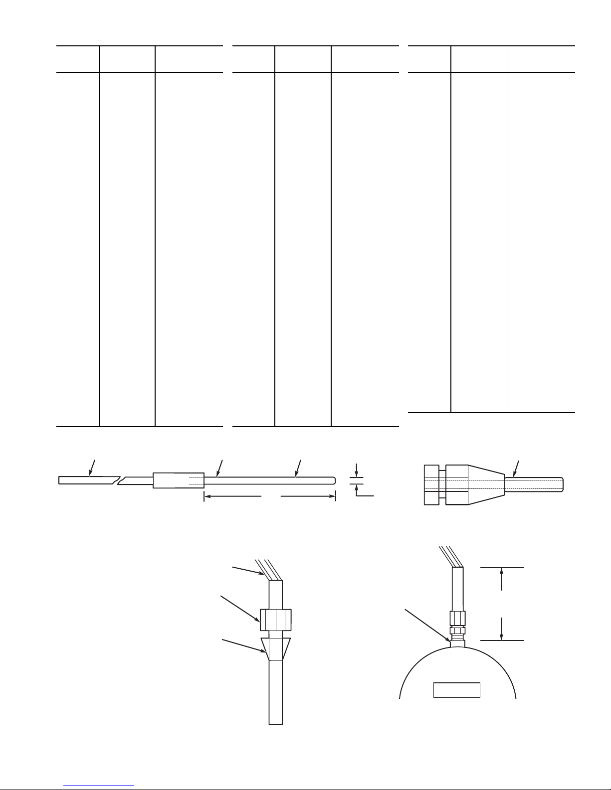
Table 39B — Thermistor Temperatures (°C) vs Resistance/Voltage Drop
(NOTE: These Values do NOT Apply to the Motor Temperature Thermistors)
TEMP
(C)
VOLTAGE
DROP
(V)
RESISTANCE
(Ohms)
−40 4.896 168 230
−39 4.889 157 440
−38 4.882 147 410
−37 4.874 138 090
−36 4.866 129 410
−35 4.857 121 330
−34 4.848 113 810
−33 4.838 106 880
−32 4.828 100 260
−31 4.817 94 165
−30 4.806 88 480
−29 4.794 83 170
−28 4.782 78 125
−27 4.769 73 580
−26 4.755 69 250
−25 4.740 65 205
−24 4.725 61 420
−23 4.710 57 875
−22 4.693 54 555
−21 4.676 51 450
−20 4.657 48 536
−19 4.639 45 807
−18 4.619 43 247
−17 4.598 40 845
−16 4.577 38 592
−15 4.554 38 476
−14 4.531 34 489
−13 4.507 32 621
−12 4.482 30 866
−11 4.456 29 216
−10 4.428 27 633
−9 4.400 26 202
−8 4.371 24 827
−7 4.341 23 532
−6 4.310 22 313
−5 4.278 21 163
−4 4.245 20 079
−3 4.211 19 058
−2 4.176 18 094
−1 4.140 17 184
0 4.103 16 325
1 4.065 15 515
2 4.026 14 749
3 3.986 14 026
4 3.945 13 342
5 3.903 12 696
6 3.860 12 085
7 3.816 11 506
8 3.771 10 959
9 3.726 10 441
TEMP
(C)
VOLTAGE
DROP
(V)
RESISTANCE
(Ohms)
10 3.680 9 949
11 3.633 9 485
12 3.585 9 044
13 3.537 8 627
14 3.487 8 231
15 3.438 7 855
16 3.387 7 499
17 3.337 7 161
18 3.285 6 840
19 3.234 6 536
20 3.181 6 246
21 3.129 5 971
22 3.076 5 710
23 3.023 5 461
24 2.970 5 225
25 2.917 5 000
26 2.864 4 786
27 2.810 4 583
28 2.757 4 389
29 2.704 4 204
30 2.651 4 028
31 2.598 3 861
32 2.545 3 701
33 2.493 3 549
34 2.441 3 404
35 2.389 3 266
36 2.337 3 134
37 2.286 3 008
38 2.236 2 888
39 2.186 2 773
40 2.137 2 663
41 2.087 2 559
42 2.039 2 459
43 1.991 2 363
44 1.944 2 272
45 1.898 2 184
46 1.852 2 101
47 1.807 2 021
48 1.763 1 944
49 1.719 1 871
50 1.677 1 801
51 1.635 1 734
52 1.594 1 670
53 1.553 1 609
54 1.513 1 550
55 1.474 1 493
56 1.436 1 439
57 1.399 1 387
58 1.363 1 337
59 1.327 1 290
TEMP
(C)
VOLTAGE
DROP
(V)
RESISTANCE
(Ohms)
60 1.291 1 244
61 1.258 1 200
62 1.225 1 158
63 1.192 1 118
64 1.160 1 079
65 1.129 1 041
66 1.099 1 006
67 1.069 971
68 1.040 938
69 1.012 906
70 0.984 876
71 0.949 836
72 0.920 805
73 0.892 775
74 0.865 747
75 0.838 719
76 0.813 693
77 0.789 669
78 0.765 645
79 0.743 623
80 0.722 602
81 0.702 583
82 0.683 564
83 0.665 547
84 0.648 531
85 0.632 516
86 0.617 502
87 0.603 489
88 0.590 477
89 0.577 466
90 0.566 456
91 0.555 446
92 0.545 436
93 0.535 427
94 0.525 419
95 0.515 410
96 0.506 402
97 0.496 393
98 0.486 385
99 0.476 376
100 0.466 367
101 0.454 357
102 0.442 346
103 0.429 335
104 0.416 324
105 0.401 312
106 0.386 299
107 0.370 285
THERMISTOR JACKETED CABLE SENSOR TUBE BEND SLIGHTLY BEFORE WELL INSERTION
3/16 in.
4 in.
THERMISTOR WELL
Fig. 21 — Thermistor Replacement (T1, T2, T5, or T6)
X
COOLER
MEASURE TO TOP
OF WELD COUPLING
FOR PROPER
INSERTION
(SEE TABLE 41)
PACKING NUT
FERRULE
LEAD END (30GX080-176, ALL 30HX)
PLUG END (30GX205-265)
Fig. 22 — Thermistor (Liquid Level Sensor) Replacement
61
Page 62
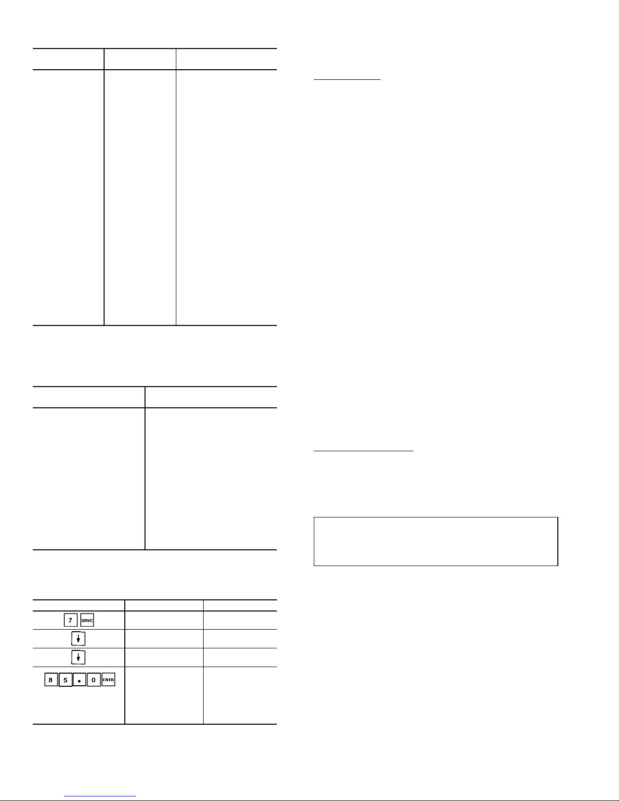
Table 40 — Thermistor Temperatures vs
Resistance, Motor Temperature Thermistors
TEMP
(F)
TEMP
(C)
RESISTANCE
(Ohms)
−22 −30 88,480.0
−13 −25 65,205.0
−4 −20 48,536.0
5 −15 36,476.0
14 −10 27,663.0
23 −5 21,163.0
32 0 16,325.0
41 5 12,696.0
50 10 9,949.5
59 15 7,855.5
68 20 6,246.0
77 25 5,000.0
86 30 4,028.4
95 35 3,265.7
104 40 2,663.2
113 45 2,184.2
122 50 1,801.2
131 55 1,493.1
140 60 1,243.9
149 65 1,041.4
158 70 875.8
167 75 739.7
176 80 627.6
185 85 534.9
194 90 457.7
203 95 393.3
212 100 339.3
221 105 293.8
230 110 255.3
239 115 222.6
248 120 194.8
NOTE: Motor temperature thermistor values must be verified using
resistance. Voltage drop cannot be used.
Table 41 — Thermistor Depth
UNIT MODEL
NUMBER
THERMISTOR DEPTH
‘‘X’’-in. (mm)
30GX080-090 6.00 (152.4)
30GX105-115 4.25 (108.0)
30GX125-136 5.56 (141.2)
30GX150,151 6.00 (152.4)
30GX160,161 4.25 (108.0)
30GX175,176 4.25 (108.0)
30GX205-226 3.94 (100.0)
30GX250-265 4.82 (122.4)
30HXA,C076-086 5.13 (130.3)
30HXA,C096 6.00 (152.4)
30HXA,C106 4.25 (108.0)
30HXA,C116-126 5.13 (130.3)
30HXA,C136-146 6.00 (152.4)
30HXA,C161-171 4.25 (108.0)
30HXA,C186 5.56 (141.2)
30HXA,C206 3.94 (100.0)
30HXA,C246-271 4.82 (122.4)
Table 42 — Calibrating Pressure Transducers
(Pressure Gage Installed)
KEYPAD ENTRY DISPLAY RESPONSE COMMENTS
CALIBRATION
OFFSET
CIRCUIT A
PRESSURE
Discharge Pressure
84.2 PSI
Current reading is
displayed.
Discharge Pressure
85.0 PSI
Enter gage pressure
reading to nearest
tenth. Control will
allow offset of up to
6 psig. Transducer
calibration is now
complete.
Safety Devices — The 30GX/HX chillers contain many
safety devices and protection logic built into the electronic
control. Following is a description of the major safeties.
COMPRESSOR PROTECTION
Motor Overload — One factory preset solid-state overload
protects each compressor against overcurrent. Do not bypass the overload or make any changes to the overload
setting. Determine the cause for trouble and correct the problem before resetting a tripped overload. In addition to the
overload, each compressor is further protected by the
Compressor Protection Module. Each module has a factory
installed and configured 8-pin header. The configuration of
this header defines the must-trip amps at which the CPM
will turn the compressor off. SeeAppendixD for correct setting of overload and configuration headers.
Each CPM board also reads the status of each compressor’s high-pressure switch. All compressors have factoryinstalled high-pressure switches. For 30GX units, the switch
is set to trip at 303 ± 7 psig (2089 ± 48 kPa). The setting
for 30HXA units is 275 ± 7 psig (1896 ± 48 kPa) and for
30HXC units the setting is 191 ± 7 psig (1317 ± 48 kPa).
If the switch opens during operation, the compressor will be
shut down. The CPM will reset automatically when the
switch closes, however, a manual reset is required to restart
the compressor.
OIL SEPARATOR HEATERS(30GX)— Each oil separator
circuit has a heater mounted on the underside of the vessel.
The heater is energized with control circuit power. After a
prolonged shutdown or service job, additional time may be
required before starting the unit. Oil heaters are energized
when the discharge gas temperature falls below 105 F
(40.6 C). The heaters are deenergized when the discharge
gas temperature rises above 110 F (43.3 C). The control will
allow the chiller to attempt to start with the heaters energized and will keep the heaters on, even when running, until
the discharge gas temperature reaches 110 F (43.3 C). Note
that the oil heaters are deenergized if the oil level switch is
open.
COOLER PROTECTION
Low Water Temperature — Microprocessor is programmed
to shut the chiller down if the leaving fluid temperature drops
below 34 F (1.1 C) for water or more than 8° F (4.4° C)
below set point for brine units. When the fluid temperature
rises 6° F (3.3° C) above the leaving fluid set point, the safety
resets and the chiller restarts. Reset is automatic as long as
this is the first occurrence of the day.
IMPORTANT: If the unit is installed in an area where
ambient temperatures fall below 32 F (0° C), inhibited
ethylene glycol or other suitable solution must be used
in the chilled fluid circuit.
Relief Devices — Fusible plugs are located in each cir-
cuit (30GX only) between the condenser and the liquid line
shutoff valve.
PRESSURE RELIEFVALVES — Valves are installed in each
circuit and are located on all coolers. One relief valve is also
installed on each 30HXC condenser. Both circuits’ oil separators on 30GX and 30HXA units have factory-installed
relief valves as well. These valves are designed to relieve if
an abnormal pressure condition arises. Relief valves on all
coolers and 30HXC condensers relieve at 220 psi (1517 kPa).
Relief valves on 30GX and 30HXA oil separators relieve at
320 psi (2206 kPa). Units with factory-installed suction service valves also have a relief valve in each compressor discharge line. These valves are designed to relieve at 350 psig
(2413 kPa). These valves should not be capped. If a valve
relieves, it should be replaced. If the valve is not replaced,
it may relieve at a lower pressure, or leak due to trapped dirt
from the system which may prevent resealing.
62
Page 63
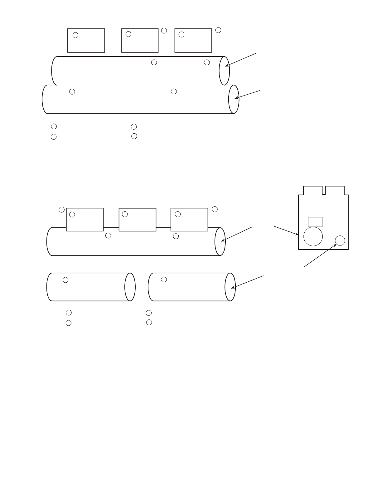
COMPRESSOR A1
COMPRESSOR B1
3
3
2
1
COOLER
CONDENSER (30HXC MODEL)
OIL SEPARATOR (30HXA MODEL)
2
1
4
4
1
2
3
3
4
DISCHARGE PRESSURE
SUCTION PRESSURE
OIL PRESSURE
ECONOMIZER PRESSURE (LOCATED IN MOTOR COOLING LINE)
COMPRESSOR A2
(206-271 ONLY)
Fig. 23A — 30HX Pressure Transducer Locations
COMPRESSOR A1
COMPRESSOR B1
COOLER
OIL SEPARATORS
(ONE VESSEL ON
SMALL GX'S, TWO
SEPARATE ON LARGER
UNITS)
1
2
3
4
DISCHARGE PRESSURE
SUCTION PRESSURE
OIL PRESSURE
ECONOMIZER PRESSURE (LOCATED IN MOTOR COOLING LINE)
4
4
3
3
2
2
1
1
3
COMPRESSOR A2
(205-265 ONLY)
Fig. 23B — 30GX Pressure Transducer Locations
63
Page 64

Pressure relief valves locatedoncoolerandcondensershells
and 30HXA oil separator shells have3⁄4-in. NPT connections for relief. The 30GX oil separators have1⁄2-in. male
flare connections. Some local building codes require that relieved gases be removed. This connection allows conformance to this requirement.
Control Modules
Turn controller power offbeforeservicingcontrols.This
ensures safety and prevents damage to controller.
PROCESSOR MODULE (PSIO-1), HIGH-VOLTAGE
RELAY MODULE (DSIO-HV), AND EXV DRIVER
MODULE (DSIO-EXV), 12/6 MODULE (PSIO-2) — The
PSIO and DSIO modules all perform continuous diagnostic
evaluations of the condition of the hardware. Proper operation of these modules is indicated by LEDs on the front surface of the DSIOs, and on the top horizontal surface of the
PSIOs.
RED LED — Blinking continuously ata1to2second rate
indicates proper operation. Lighted continuously indicates a
problem requiring replacement of module. Off continuously
indicates power should be checked. If there is no input power,
check fuses. If fuse is bad, check for shorted secondary of
transformer, tripped circuit breaker or bad module. On the
PSIO module, if the light is blinking at a rate of twice per
second, the module should be replaced.
GREEN LED — On a PSIO module, this is the green LED
closest to COMM connectors. The other green LED on module indicates externalcommunications,whenused.GreenLED
should always be blinking when power is on. It indicates
modules are communicating properly. If green LED is not
blinking, check red LED. If red LED is normal, check module address switches. Correct addresses are as follows:
PSIO-1 (Processor Module) — 01
CPM-A1 (Protection Module) — 21
CPM-A2 (Protection Module) — 29
CPM-B1 (Protection Module) — 37
DSIO (EXV Driver Module) — 50
DSIO-HV (Relay Module) — 62
PSIO-2 (12/6 I/O Module) — 74
The first number of the address for a DSIO module should
be set on the switch closest to the silver mounting plate.
If all modules indicate communication failure, check
COMM plug on PSIO-1 module for proper seating. If a good
connection is assured and condition persists, replace PSIO-1
module.
If only a DSIO module indicates communication failure,
check COMM plug on that module for proper seating. If a
good connection is assured and the condition persists, replace the DSIO module.
All system operating intelligence rests in the PSIO-1 module, the module that controls unit. This module monitors
conditions through input and output ports and through
DSIO modules (high-voltage relay module and EXV driver
module).
The machine operator communicates with microprocessor through keypad and display module. Communication between PSIO and other modules is accomplished by a 3-wire
sensor bus. These 3 wires run in parallel from module to
module.
On sensor bus terminal strips, terminal 1 of PSIO module
is connected to terminal 1 of each of the other modules.
Terminals 2 and 3 are connected in the same manner. See
Fig. 24. If a terminal 2 wire is connected to terminal 1, system does not work.
In the 30GX,HX control box, the processor module
(PSIO-1), DSIO-HV, keypad and display module and 5 vdc
power supply are all powered from a common 21 vac power
source (PSIO-1 and HSIO powered from 24 vac source on
30HX units) which connects to terminals 1 and 2 of the power
connector on each module.Aseparate source of 21 vac power
is used to power the PSIO-2 module and liquid level sensor
heaters. A separate 12.5 vdc power source is used for
the DSIO-EXV module through terminals 1 and 2 on the
power connector.TheCPMmodulesareconnected to 24 vac
power sources. Refer to Table 43 for control troubleshooting
information.
Carrier Comfort Network (CCN) Interface — The
30GX,HX chiller units can be connected to the CCN if desired.Thecommunicationbuswiringis a shielded, 3-conductor
cable with drain wire and is supplied and installed in the
field. The system elements are connected to the communication bus in a daisy chain arrangement as shown in Fig. 24.
The positive pin of each system element communication connector must be wired to the positive pins of the system elements on either side of it. This is also required for the negative and signal ground pins of each system element. Wiring
connections for CCN should be made at the COMM1 plug
on the PSIO-1 module. Consult the CCN Contractor’sManual
for further information.
NOTE: Conductors and drain wire must be 20 AWG (American Wire Gage) minimum stranded, tinned copper. Individual conductors must be insulated with PVC, PVC/
nylon, vinyl, Teflon, or polyethylene. An aluminum/polyester
100% foil shield and an outer jacket of PVC, PVC/nylon,
chrome vinyl, or Teflon with a minimum operating temperature range of −20 C to 60 C is required. Wire manufactured byAlpha (2413 or 5463),American(A22503),Belden
(8772), or Columbia (02525) meets the above mentioned
requirements.
It is important when connecting to a CCN communication
bus that a color coding scheme be used for the entire network to simplify the installation. It is recommended that red
be used for the signal positive, black for the signal negative,
and white for the signal ground. Use a similar scheme for
cables containing different colored wires.
At each system element, the shields of its communication
bus cables must be tied together. If the communication bus
is entirely within one building, the resulting continuous shield
must be connected to a ground at one point only. If the communication bus cable exits from one building and enters another, the shields must be connected to grounds at the lightning suppressor in each building where the cable enters or
exits the building (one point per building only). To connect
the unit to the network:
1. Turn off power to the control box.
2. Cut the CCN wire and strip the ends of the red (+), white
(ground), and black (−) conductors. (Substitute appropriate colors for different colored cables.)
64
Page 65
Table 43 — Compressor Control Troubleshooting
SYMPTOMS CAUSE REMEDY
COMPRESSOR DOES NOT
RUN
Power line open Check main disconnect.
Control fuse open Check control circuit for ground or short. Replace fuse.
High-Pressure Switch (HPS) tripped Move LOCAL/OFF/REMOTE switch to OFF position
then back to LOCAL or REMOTE position.
Tripped motor overload Check the controls. Find cause of trip. Reset overload.
Loose terminal connection Check connections.
Improperly wired controls Check wiring and rewire.
Low line voltage Check line voltage. Determine location of voltage drop
and remedy deficiency.
Compressor motor defective Check motor winding for open or short. Replace com-
pressor if necessary.
Seized compressor Replace compressor.
Pre-lubrication not successful Check oil pump operation, oil pressure transducer, verify
oil level/flow switch operation.
COMPRESSOR CYCLES
OFF ON LOW PRESSURE
Loss of charge Repair leak and recharge.
Bad transducer Replace transducer.
Low refrigerant charge Add refrigerant.
Failed expansion device Repair/replace as needed.
COMPRESSOR SHUTS
DOWN ON HIGH PRESSURE CONTROL
High-pressure switch erratic in action Replace switch.
Compressor discharge valve partially closed Open valve or replace if defective.
Condenser fan(s) not operating (air cooled units) Check wiring. Repair or replace motor(s) if defective.
Condenser coil plugged or dirty (air cooled units) Clean coil.
Condenser water valve not operating (water
cooled units)
Check wiring. Repair or replace valve if defective
Circuit overcharged Clean condenser.
Liquid valve closed* Open valve or replace if defective.
UNIT OPERATES LONG OR
CONTINUOUSLY
Low refrigerant charge Add refrigerant.
Control contacts fused Replace control.
Partially plugged or plugged expansion valve or
filter drier
Clean or replace.
Defective insulation Replace or repair.
Service load exceeding design capacity Keep doors and windows closed.
Inefficient compressor Check loader solenoid valves. Replace if necessary.
SYSTEM NOISES Piping vibration Support piping as required.
Expansion valve hissing Add refrigerant.
Check for plugged liquid line filter drier.
Compressor noisy Replace compressor (worn bearings).
Check for loose compressor bolts securing compressor
to cooler.
COMPRESSOR LOSES OIL Leak in system Find and repair leak.
Mechanical damage to rotors Replace compressor.
HOT LIQUID LINE Shortage of refrigerant due to leak Repair leak and recharge.
FROSTED LIQUID LINE Shutoff valve partially closed or restricted Open valve or remove restriction.
COMPRESSOR LOADERS
NOT WORKING PROPERLY
Burned out coil Replace coil.
Defective capacity control valve Replace valve.
Miswired solenoid Rewire correctly.
*30GX251, 265 sizes have two Circuit A discharge and liquid valves.
1
2
3
1
2
3
1
2
3
1
2
3
1
2
3
1
2
3
1
2
3
CPM-B1CPM-A1HSIO-IIPSIO-2-J8DSIO-EXV-J2
DSIO-HV-J2
PSIO-1-J8
Fig. 24 — Sensor Bus Wiring (Communications)
65
Page 66
3. Removethe 4-pin female plug from the PSIO-1 COMM1
plug and connect the red wire to terminal 1 of the plug,
the white wire to terminal 2, and the black wire to terminal 3.
4. Insert the plug back into the COMM1 plug.
IMPORTANT: A shorted CCN bus cable will prevent
some routines from running and may prevent the unit
from starting. If abnormal conditions occur, unplug the
connector.Ifconditions return to normal, check the CCN
connector and cable. Run new cable if necessary. A
short in one section of the bus can cause problems with
all system elements on the bus.
PROCESSOR MODULE (PSIO-1)
Inputs — Each input channel has 3 terminals; only 2 of the
terminals are used.Applicationofmachinedetermineswhich
terminals are used. Always refer to the individual unit wiring for terminal numbers.
Outputs — Output is 20 vdc or 4 to 20 mA. There are 3 terminals, only 2 of which are used, depending on the application. Refer to unit the wiring diagram.
NOTE: The 12/6 Input/Output module (PSIO-2) has identical input and output configurations as the PSIO-1. There is
NO operating software in the PSIO-2 module.
HIGH VOLTAGE RELAY MODULE (DSIO-HV)
Inputs — Inputs on strip J3 are discrete inputs (ON/OFF).
When 24-vac power is applied across the 2 terminals in a
channel it reads the input as an On signal. Zero volts input
is read as an Off signal.
Outputs — TerminalstripsJ4andJ5areinternalrelayswhose
coils are signaled to be turned on and off by the microprocessor (PSIO-1). The relays switch the circuit to which
they are connected. No power is supplied to these connections by DSIO-HV module.
Replacing Defective Processor Module — The
PSIO-1 module replacement part number is 30GX500110.
The unit model and serial numbers are printed on the unit
nameplate located on an exterior corner post (30GX) or the
corner of the control box (30HX). The proper software and
unit configuration data is factory installed by Carrier in the
replacement module. Therefore, when ordering a replacement processor module (PSIO-1), specify the replacement
part number, full unit model number, and serial number. If
these numbers are not provided, the replacement module will
be downloaded with the base software. The base software
settings must be reconfigured by the installer in the field.
Verify the existing PSIO-1 module is defective by using
the procedure described in the Control Modules section.
Refer to Start-up Checklist for 30GX,HX Liquid Chillers
(completed at time of original start-up) found in the job folder .
This information is needed later in this procedure. If the
checklist does not exist, fill out the current factory and
service configurationcodes( ) sectionsonanew checklist. Tailor the various options and configurations as needed
for this particular installation.
Electrical shock can cause personal injury. Disconnect
all electrical power before servicing.
1. Check that all power to unit is off. Carefully disconnect
all wires from defective module by unplugging the 6 connectors. It is not necessary to remove any of the individual wires from the connectors. Remove the screws
securing the green ground wire and communication drain
wire. Save the screws.
2. Remove the defective PSIO-1 module by removing its
mounting screws with a Phillips screwdriver, and removing the module from the control box. Save thescrews
for later use.
3. Use a small screwdriver to set the address switches S1
and S2 on the new PSIO module to exactly match the
settings on the defective module.
4. Package the defective module in the carton of the new
module for return to Carrier.
5. Mount the new module in the unit control box using a
Phillips screwdriver and the screws saved in Step 2.
6. Reinstall all 6 wire connectors, the green ground wire,
and the communications drain wire.
7. Carefully check all wiring connections before restoring
power.
8. Verify the LOCAL/OFF/REMOTE switch is in the
OFF position.
9. Restore control power. Verify the red and green lights
on top of the PSIO-1 and on front of each DSIO module
respond as described in Control Modules section. The
keypad and display module should also begin its rotating display.
Using the keypad and display module, press to
verify that the software version number matches the
ER (engineering requirement) number shown on the
PSIO-1 label.
10. Press , scroll down one level at a time, and check
the 3 factory and 2 service configuration codes as re-
corded on checklist. These codes must exactly match the
codes stored in the previous PSIO-1 module for proper
unit operation. These should already be downloaded if
the proper information was supplied when ordering the
replacement module. If the codes do not match, the codes
must be entered by the procedure described in the factory service code section of Table 22.
11. Once all codes have been verified, and all configurations, set points, and schedules re-entered, return the
LOCAL/OFF/REMOTE switch to its previous position.
WinterShutdown Preparation — At the end of each
cooling season the fluid should be drained from the system.
However, due to the cooler circuiting, some fluid will remain in the cooler after draining. To prevent freeze-up damage to the cooler tubes perform the following procedure.
1. If accessory cooler heaters have been installed, deener-
gize the heaters to prevent damage and possible safety
hazards when draining, or when there is no liquid in the
system. Remove Fuse 1 to deenergize the heaters. Drain
the fluid from the system.
2. Isolate the cooler from the rest of the system with water
shut off valves.
3. Fill the cooler with an appropriate amount of unhibited
ethylene glycol solution (or other suitable corrosioninhibitive antifreeze) for 15° F (8.3° C) below the expected low ambient conditions.
4. Leavethe cooler filled with the antifreeze solution for the
winter, or drain if desired. Be sure to deenergize heaters
(if installed) as explained in Step 1 to prevent damage.
Use an approved method of disposal when removing the
antifreeze solution.
66
Page 67
PRE-START-UP PROCEDURE
IMPORTANT: Before beginning Pre-Start-Up or StartUp, complete the Start-Up Checklist for the 30GX,HX
Liquid Chillers on pages CL-1 to CL-8. This Checklist assures proper start-up of the chiller, and provides
a record of unit condition, application requirements,
system information and operation at initial start-up. The
checklist should be removed from the manual and kept
with the job file for future reference.
IMPORTANT: DO NOTATTEMPTTOSTARTTHE
CHILLER UNTILTHE FOLLOWING CHECKSHAVE
BEEN COMPLETED.
System Check
1. Check all auxiliary components such as the chilled fluid
circulating pump, air-handlingequipment,orotherequipment to which the chiller supplies liquid. Consult the
manufacturer’s instructions. If the unit has field-installed
accessories, be sure all are properly installed and wired
correctly. Refer to the unit wiring diagrams.
2. Check the cooler flow switch for proper configuration
and operation ( from HSIO). Ensure the switch
closes when the pump is on and opens when the pump
is turned off. A flow switch must be installed.
3. Openthedischargeandliquidvalvesineach circuit. The
discharge shutof fvalvesarein-lineballtypeandareopen
when parallel with the refrigerant flow.
4. If factory-installed option is installed, open the suction
service valves in each circuit. Service valve is located
below the compressor in the cooler suction connection
flange.
5. Open the oil shutoff valves located by the oil pre-filter.
Open bubbler tube valve on 30HX machines equipped
with economizers.
6. Check the tightness of all electrical connections. Check
incoming power supply for proper nameplate voltage.
7. Check to ensure the unit is level per the installation
instructions.
8. Check the incoming power supply for proper phasing.
This can be done by turning on both the line voltage and
control voltage power supplies. Leave the LOCAL/OFF/
REMOTE switch in the OFF position. If the incoming
power is not phased correctly, the CPM will generate
an alarm for voltage phase reversal. Press for
CircuitAand for Circuit B at the HSIOtocheck
for this alarm. Scroll up and locate the Feedback value
(displayed in units of volts). If a value of 7.0 appears, a
voltage phase reversal has been identified and requires
incoming power supply phase change. If this is the case,
shut down all power supplies and switch any 2 incoming power leads at the control box terminal block.
DO NOT make any changes to the factory installed
compressor power wiring in the control box or at
the compressor junction box. Doing so will cause
permanent damage to the compressor and will require compressor replacement. Proper phasing has
already been checked at the factory.
For those units with 2 incoming terminal blocks, the voltage sequence is sensed at one terminal block only.Check
the phasing to ensure that both circuits match.
If the incoming power is still phased incorrectly at the
second terminal block, a current phase reversal alarm
will be generated when an attempt is made to start this
compressor. The compressor will be shut down within
15 milliseconds. To correct this, interchange 2 power
leads at this terminal block only.
9. Check all field configuration data and set points.
10. Enter correct date, time, and operating schedule(s).
11. Verify operation of solenoids, pumps, valves, compressors, fans, etc. as listed in the Checklist.
12. Open condenser water valves. Check condenser water
pump for proper operation (30HX).
START-UP AND OPERATION
Actual Start-Up —
Actual start-up should be done only
under supervision of a qualified refrigeration mechanic and
qualified Carrier Comfort Network personnel.
1. Set leaving fluid temperature. No cooling range adjust-
ment is necessary.
2. Start chilled fluid pump and condenser pump (30HXC) if
not controlled by unit.
3. Switch LOCAL/OFF/REMOTE switch to LOCAL or
REMOTE.
4. Provided there is a load on the chiller, allow the machine
to operate and confirm that everything is functioning properly.Verify that the leaving fluid temperature agrees with
the cooling set point (1 or 2), or if reset is being used, the
modified set point. Chiller is controlling to the Control
Point displayed under .
OperatingSequence— The chiller is started by switch-
ing the LOCAL/OFF/REMOTE switch to either LOCAL or
REMOTE. On a command for cooling, the oil pump is turned
on to start the pre-lubrication process. After 20 seconds, the
oil solenoid is opened and the control reads the oil pressure
from the transducer and determines if sufficient pressure has
been built up. If there is not sufficient pressure, an alarm is
generated after the second attempt and the compressor is not
started.
Upon building pressure, the compressor is allowed to start.
For across-the-line (XL) start chillers, the compressor starts
and comes up to full speed within 1 to 3 seconds. For WyeDelta start chillers, contactors 1M and S (starter contactor
assembly) are closed and the compressor is started in a Wye
configuration. This method reduces the locked rotor current
requirements by approximately60%whilemaintainingenough
torque to bring the compressor up to full speed.
After 5 seconds, the CPM module switches out contactor
S and brings in contactor 2M, which runs the motor in a
Delta configuration (same configuration in which XL units
run). The oil pump will shut off within 10 seconds after the
compressor is started. Once the compressor is successfully
running, the control loads the compressor and adds additional stages of capacity as needed to satisfy the leaving fluid
set point. Head pressure is controlled by fan cycling (30GX)
or can be controlled with a field installed accessory Motormastert III controller (30GX) or field installed condenser
water valves (30HX).
If cooler pump controlisenabled,thecoolerpumpis started.
If condenser pump control (30HXC) is enabled, the condenser pump is started (Type 1).
67
Page 68
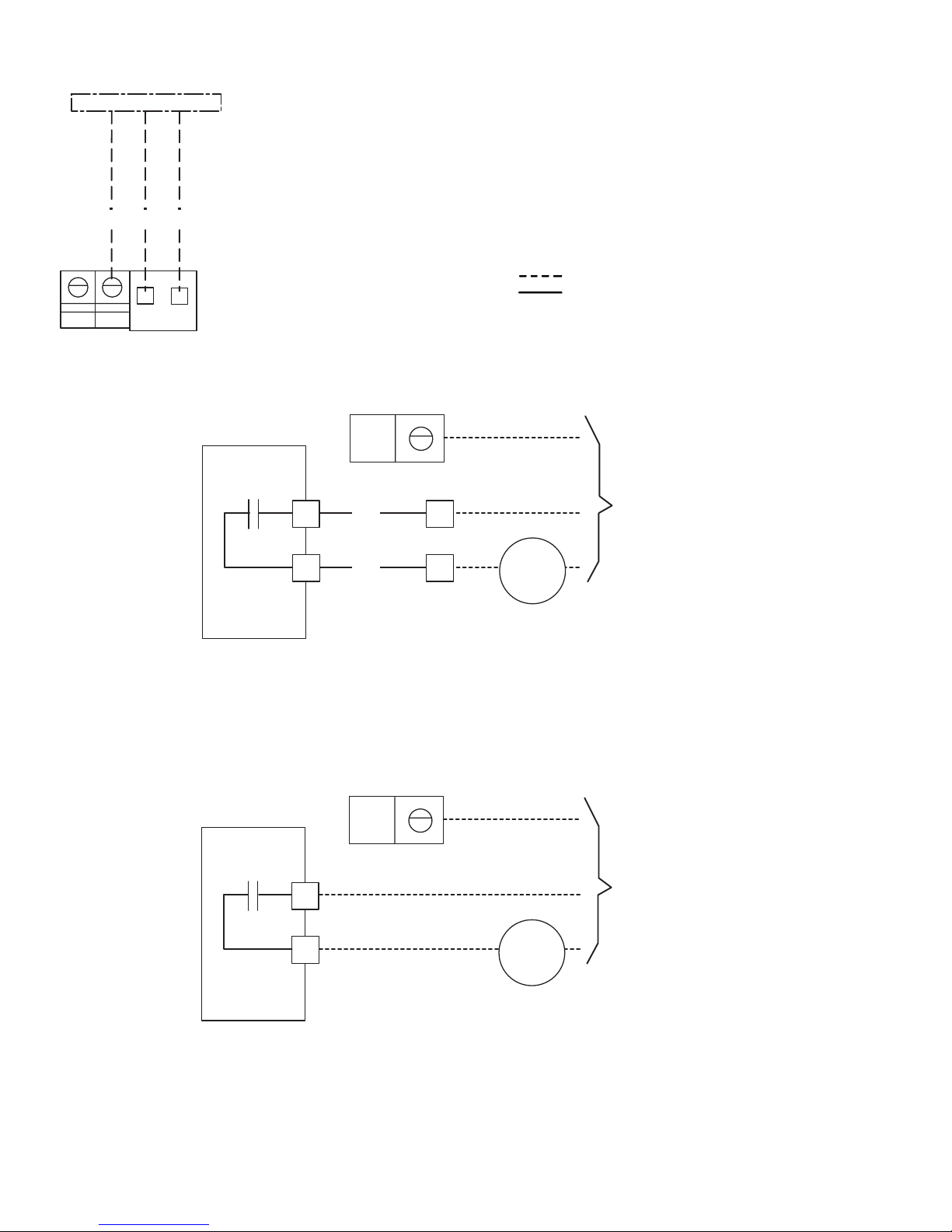
FIELD WIRING
Field wiring is shown in Fig. 25-37.
LEGEND FOR FIG. 25-37
ALM — Alarm
C—Contactor
CFC — Condenser Fan Contactor
CPR — Condenser Pump Relay
CWP — Chilled Water Pump
DSIO — High Voltage Relay Module
EQUIP — Equipment
EXV — Electronic Expansion Valve
FU — Fuse
GFI-CO — Ground Fault Interrupter Convenience Outlet
GND — Ground
NEC — National Electrical Code
PL — Plug
PSIO — Processor Sensor Input/Output Module
RB — Relay Board
TB — Terminal Block
Field-Wired
Factory Wired
FIELD CONTROL POWER SUPPLY
NEC FUSED DISCONNECT
230 V CONTROL CIRCUITS
USE 15 AMP MAXIMUM FROM
SEPARATE POWER SUPPLY
115 V CONTROL CIRCUITS
USE 30 AMP MAXIMUM FROM
SEPARATE POWER SUPPLY
2
1
GND
TB4
Fig. 25 — Power Supply Wiring
EQUIP GND
TB2
TB2
BLK
BLK
T1
T2
K6
SEPARATE
115 OR 230 V
FIELD POWER
SUPPLY
RELAY BOARD 1
2
3
ALM
MAX. LOAD ALLOWED FOR THE ALARM RELAY IS
125 VA SEALED, 1250 VA INRUSH AT 115 OR 230 VOLT.
FIELD SUPPLIED
Fig. 26 — Remote Alarm Relay Accessory Wiring; 30HXA,C
RELAY BOARD 2
K3
T4
T3
SEPARATE
115 OR 230 V
FIELD POWER
SUPPLY
EQUIP GND
ALM
MAX. LOAD ALLOWED FOR THE ALARM RELAY IS
125 VA SEALED, 1250 VA INRUSH AT 115 OR 230 VOLT.
FIELD SUPPLIED
Fig. 27 — Remote Alarm Relay Accessory Wiring; 30GX
68
Page 69
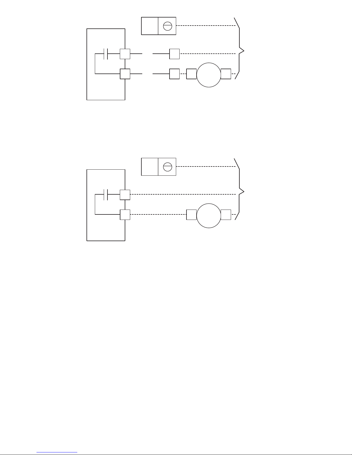
RELAY BOARD 1
K3
T4
T3
BLK
BLK
TB2
TB2
4
5
C1
C2
EQUIP GND
SEPARATE
115 OR 230 V
FIELD POWER
SUPPLY
CWP
MAX. LOAD ALLOWED FOR THE CWP RELAY IS
125 VA SEALED, 1250 VA INRUSH AT 115 OR 230 VOLT.
ACCESSORY ONLY
Fig. 28 — Chilled Water Pump Relay Wiring; 30HXA,C
SEPARATE
115 OR 230 V
FIELD POWER
SUPPLY
K3
RELAY BOARD 1
EQUIP GND
C2C1
T3
T4
CWP
MAX. LOAD ALLOWED FOR THE CWP RELAY IS
125 VA SEALED, 1250 VA INRUSH AT 115 OR 230 VOLT.
ACCESSORY ONLY
Fig. 29 — Chilled Water Pump Relay Wiring; 30GX
69
Page 70
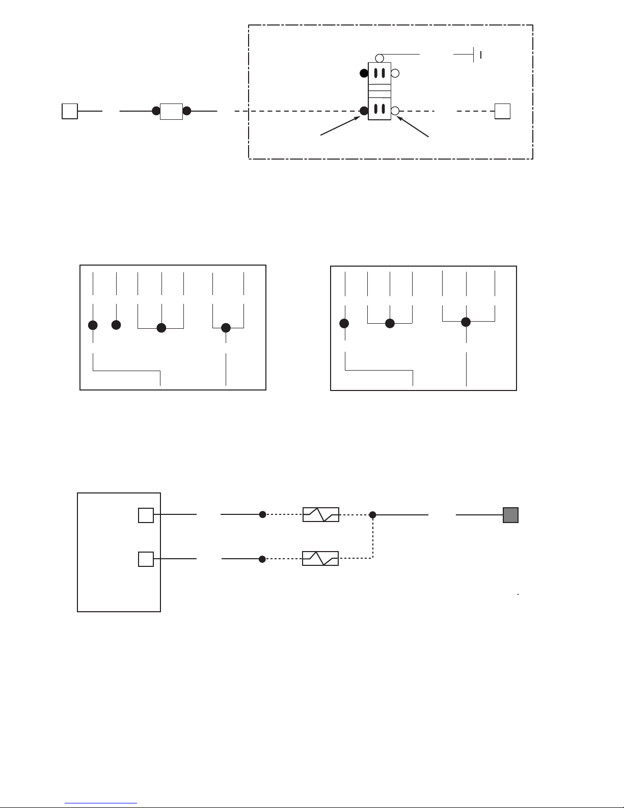
GFI-CO
GRN/YEL
SILVER SCREWSBRASS SCREWS
BLK
BLU
1
15 AMPS
FU1
TEST
RESET
ACCESSORY
TB4
WHT
TB4
2
Fig. 30 — Ground Fault Interrupter-Convenience Outlet Accessory Wiring
BRN
BRN
VIO
VIO
PNK
PNK
ORN BLU
BLU
BLU
RED
REDBLU
ORN
BLK
BLK
BLK
BLK
230V CONTROL CIRCUIT WIRING 115V CONTROL CIRCUIT WIRING
Fig. 31 — Oil Pump Motor Junction Box Wiring
TB4
WHT
2
MINIMUM LOAD CONTROL CIRCUIT B
MINIMUM LOAD CONTROL CIRCUIT A
GRA
PNK
T3
T1
RELAY BOARD 2
NOTE: Gray, Pink, and White wires are included in the control box as part of the factory wire harness. Field supplied and installed wire is needed
from control box to solenoid valves.
Fig. 32 — Minimum Load Valve Accessory Wiring
70
Page 71
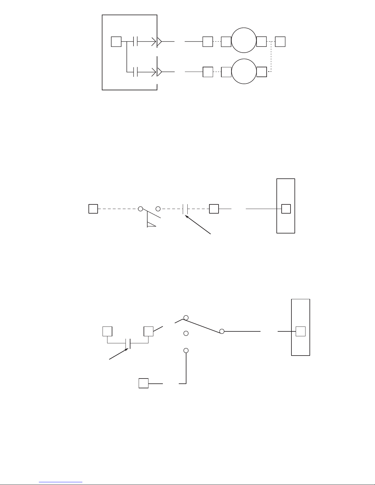
T6
BLK
K5
RB2PL2-3
RELAY BOARD 2
K4
RB2PL2-5
C1
C2
2
TB2
6
C1
C2
TB2
CPR/
CFCB
BLK
1
CFCA
TB4
FIELD SUPPLIED
Fig. 33 — Condenser Pump Relay Wiring, 30HXC and Remote Condenser Fan On/Off Wiring, 30HXA
COOLER FLOW SWITCH
11
RED
CHILLED WATER
PUMP INTERLOCK
CONTACTS
TB2
3
DSIO (EXV)-J3
TB2
12
Fig. 34 — Chilled Water Interlock and Flow Switch Input Wiring
13 14
RED
OFF
REMOTE ON/OFF
CONTACTS
REMOTE
TB2 TB2
TB2
1
RED
RED
DSIO (EXV)-J3
12
Fig. 35 — Remote On/Off Switch Input Wiring
MAX. LOAD ALLOWED AT TB2-1 AND TB2-6 IS
125 VA SEALED, 1250 VA INRUSH AT 115 OR 230 VOLTS.
71
Page 72
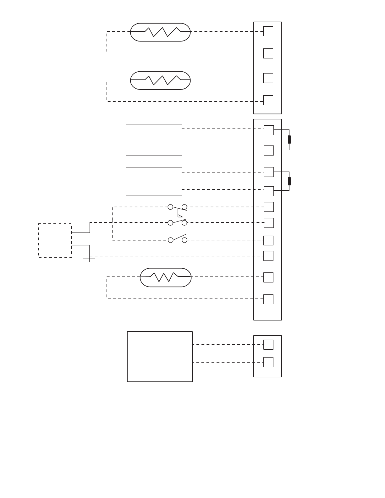
FIELD SUPPLIED
AND POWERED
4-20 mA SIGNAL
FIELD SUPPLIED
AND POWERED
4-20 mA SIGNAL
OUTDOOR AIR THERMISTOR
FIELD SUPPLIED
4-20 mA
WATER
VALVE
+
-
+
-
4-20 mA SIGNAL
GENERATOR
TEMPERATURE
RESET
4-20 mA SIGNAL
GENERATOR
DEMAND LIMIT
47
46
36
35
31
28
23
22
20
19
CONDENSER ENTERING
WA TER THERMIST OR
FIELD SUPPLIED
CONDENSER LEAVING
WA TER THERMIST OR
FIELD SUPPLIED
+
FIELD SUPPLIED 4-20 mA
WATER VALVE
(30HXC ONLY)
PSIO-2, J6 PLUG
TOP
18
17
15
14
PSIO-2, J7 PLUGS
REMOTE DUAL SETPOINT
ICE DONE
25
500 OHM, 1/2 WATT
FIELD SUPPLIED
RESISTOR
500 OHM, 1/2 WATT
FIELD SUPPLIED
RESISTOR
CONDENSER FLOW SWITCH
BOTTOM
-
32
FIELD
SUPPLIED
24 VAC
Fig. 36 — PSIO-2 Wiring for Accessories and Field-Installed Options, 30HX Units
72
Page 73
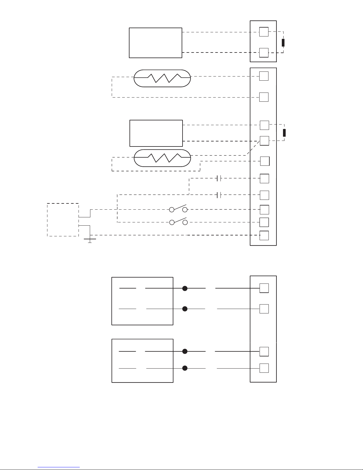
FIELD SUPPLIED
AND POWERED
4-20 mA SIGNAL
FIELD SUPPLIED
AND POWERED
4-20 mA SIGNAL
TOP
PSIO-2, J7 PLUGS
BOTTOM
4-20 mA SIGNAL
GENERATOR
TEMPERATURE
RESET
+
-
500 OHM, 1/2 WATT
FIELD SUPPLIED
RESISTOR
14
13
OUTDOOR AIR THERMISTOR
FIELD SUPPLIED
20
21
22
+
-
4-20 mA SIGNAL
GENERATOR
DEMAND LIMIT
23
500 OHM, 1/2 WATT
FIELD SUPPLIED
RESISTOR
47
46
PSIO-2, J6 PLUG
49
50
VIO
GRA
VIO
GRA
VIO
GRA
VIO
GRA
MOTORMASTER®
OPTION (080-150, 160)
CIRCUIT A (151, 161-265)
MOTORMASTER
OPTION
CIRCUIT B (151, 161-265)
31
28
REMOTE DUAL SETPOINT
ICE DONE
25
34
STAGE 2
STAGE 1
DEMAND LIMIT
EXTERNAL
SWITCH
35
FIELD
SUPPLIED
24 VAC
24
SPACE TEMPERATURE
SENSOR
FIELD SUPPLIED
Fig. 37 — PSIO-2 Wiring for Accessories and Field-Installed Options, 30GX Units
73
Page 74
APPENDIX A
Compressor Must Trip Amps (Determined by CPM Modules)
COMPRESSOR MUST TRIP AMPS
2-COMPRESSOR UNITS
Unit Size Unit Voltage
Compressor A1, B1
Must Trip Amps
30GX080
575-3-60 98, 82
380-3-60 148,124
208/230-3-60 270,226
460-3-60 122,102
230-3-50 256,212
380/415-3-50 156,128
30GX090
575-3-60 120, 82
380-3-60 180,124
208/230-3-60 328,226
460-3-60 148,102
230-3-50 310,212
380/415-3-50 188,128
30GX105
230-3-50 344,238
380/415-3-50 208,144
30GX106
575-3-60 134, 92
380-3-60 202,140
208/230-3-60 368,254
460-3-60 168,114
230-3-50 344,238
380/415-3-50 208,144
30GX115
575-3-60 162, 92
380-3-60 246,140
208/230-3-60 448,254
460-3-60 204,114
230-3-50 418,238
380/415-3-50 254,144
30GX125
575-3-60 162,110
380-3-60 246,168
208/230-3-60 448,306
460-3-60 204,138
230-3-50 418,288
380/415-3-50 254,174
30GX136
575-3-60 162,134
380-3-60 246,202
208/230-3-60 448,368
460-3-60 204,168
230-3-50 418,344
380/415-3-50 254,208
30GX150
230-3-50 344,520
380/415-3-50 208,314
30GX151
575-3-60 198,134
380-3-60 300,202
208/230-3-60 546,368
460-3-60 240,168
30GX160
230-3-50 418,520
380/415-3-50 254,314
30GX161
575-3-60 198,162
380-3-60 300,246
208/230-3-60 546,448
460-3-60 248,204
230-3-50 520,418
380/415-3-50 314,254
30GX175
230-3-50 520,520
380/415-3-50 314,314
30GX176
575-3-60 198,198
380-3-60 300,300
208/230-3-60 546,546
460-3-60 248,248
30HXA076
575-3-60 82, 82
380-3-60 124,124
346-3-50 140,140
208/230-3-60 226,226
460-3-60 102,102
230-3-50 212,212
380/415-3-50 128,128
30HXA086
575-3-60 98, 82
380-3-60 148,124
346-3-50 170,140
208/230-3-60 270,226
460-3-60 122,102
230-3-50 256,212
380/415-3-50 156,128
COMPRESSOR MUST TRIP AMPS
2-COMPRESSOR UNITS
Unit Size Unit Voltage
Compressor A1, B1
Must Trip Amps
30HXA096
575-3-60 120, 82
380-3-60 180,124
346-3-50 206,140
208/230-3-60 328,226
460-3-60 148,102
230-3-50 310,212
380/415-3-50 188,128
30HXA106
575-3-60 144, 82
380-3-60 218,124
346-3-50 250,140
208/230-3-60 400,226
460-3-60 180,102
230-3-50 376,212
380/415-3-50 228,128
30HXA116
575-3-60 144, 98
380-3-60 218,148
346-3-50 250,170
208/230-3-60 400,270
460-3-60 180,122
230-3-50 376,256
380/415-3-50 228,156
30HXA126
575-3-60 144,120
380-3-60 218,180
346-3-50 250,206
208/230-3-60 400,328
460-3-60 180,148
230-3-50 376,310
380/415-3-50 228,188
30HXA136
575-3-60 176,120
380-3-60 266,180
346-3-50 306,206
208/230-3-60 486,328
460-3-60 220,148
230-3-50 462,310
380/415-3-50 280,188
30HXA146
575-3-60 176,144
380-3-60 266,218
346-3-50 306,250
208/230-3-60 486,400
460-3-60 220,180
230-3-50 462,376
380/415-3-50 280,228
30HXA161
575-3-60 198,134
380-3-60 300,202
346-3-50 344,228
208/230-3-60 546,368
460-3-60 248,168
230-3-50 520,344
380/415-3-50 314,208
30HXA171
575-3-60 162,198
380-3-60 246,300
346-3-50 278,344
208/230-3-60 448,546
460-3-60 204,248
230-3-50 418,520
380/415-3-50 254,314
30HXA186
575-3-60 198,198
380-3-60 300,300
346-3-50 344,344
208/230-3-60 546,546
460-3-60 248,248
230-3-50 520,520
380/415-3-50 314,314
74
Page 75
APPENDIX A (cont)
Compressor Must Trip Amps (Determined by CPM Modules) (cont)
COMPRESSOR MUST TRIP AMPS
2-COMPRESSOR UNITS
Unit Size Unit Voltage
Compressor A1, B1
Must Trip Amps
30HXC076
575-3-60 56, 56
380-3-60 84, 84
346-3-50 96, 96
208/230-3-60 154,154
460-3-60 70, 70
230-3-50 144,144
380/415-3-50 88, 88
30HXC086
575-3-60 68, 56
380-3-60 102, 84
346-3-50 116, 96
208/230-3-60 186,154
460-3-60 84, 70
230-3-50 176,144
380/415-3-50 106, 88
30HXC096
575-3-60 82, 56
380-3-60 124, 84
346-3-50 140, 96
208/230-3-60 226,154
460-3-60 104, 70
230-3-50 212,144
380/415-3-50 128, 88
30HXC106
575-3-60 100, 56
380-3-60 150, 84
346-3-50 168, 96
208/230-3-60 274,154
460-3-60 124, 70
230-3-50 254,144
380/415-3-50 154, 88
30HXC116
575-3-60 100, 68
380-3-60 150,102
346-3-50 168,116
208/230-3-60 274,186
460-3-60 124, 84
230-3-50 254,176
380/415-3-50 154,106
30HXC126
575-3-60 100, 82
380-3-60 150,124
346-3-50 168,140
208/230-3-60 274,226
460-3-60 124,104
230-3-50 254,212
380/415-3-50 154,128
COMPRESSOR MUST TRIP AMPS
2-COMPRESSOR UNITS
Unit Size Unit Voltage
Compressor A1, B1
Must Trip Amps
30HXC136
575-3-60 120, 82
380-3-60 180,124
346-3-50 204,140
208/230-3-60 328,226
460-3-60 148,104
230-3-50 308,212
380/415-3-50 186,128
30HXC146
575-3-60 120,100
380-3-60 180,150
346-3-50 204,168
208/230-3-60 328,274
460-3-60 148,124
230-3-50 308,254
380/415-3-50 186,154
30HXC161
575-3-60 130, 90
380-3-60 196,136
346-3-50 220,152
208/230-3-60 358,246
460-3-60 162,112
230-3-50 332,228
380/415-3-50 202,138
30HXC171
575-3-60 108,130
380-3-60 164,196
346-3-50 182,220
208/230-3-60 298,358
460-3-60 136,162
230-3-50 274,332
380/415-3-50 166,202
30HXC186
575-3-60 130,130
380-3-60 196,196
346-3-50 220,220
208/230-3-60 358,358
460-3-60 162,162
230-3-50 332,332
380/415-3-50 202,202
75
Page 76
APPENDIX A (cont)
Compressor Must Trip Amps (Determined by CPM Modules) (cont)
COMPRESSOR MUST TRIP AMPS
3-COMPRESSOR UNITS
Unit Size Unit Voltage
Compressor A1, A2, B1
Must Trip Amps
30GX205
230-3-50 418,238,520
380/415-3-50 254,144,314
30GX206
575-3-60 198, 92,162
380-3-60 300,140,246
208/230-3-60 546,254,448
460-3-60 248,114,204
30GX225
230-3-50 520,288,520
380/415-3-50 314,174,314
30GX226
575-3-60 198,110,198
380-3-60 300,168,300
208/230-3-60 546,306,546
460-3-60 248,138,248
230-3-50 520,288,520
380/415-3-50 314,174,314
30GX250
230-3-50 520,418,520
380/415-3-50 314,254,314
30GX251
575-3-60 198,198,162
380-3-60 300,300,246
208/230-3-60 546,546,448
460-3-60 248,248,204
30GX265
575-3-60 198,198,198
380-3-60 300,300,300
208/230-3-60 546,546,546
460-3-60 248,248,248
230-3-50 520,520,520
380/415-3-50 314,314,314
30HXA206
575-3-60 162, 92,198
380-3-60 246,138,300
346-3-50 278,158,344
208/230-3-60 448,254,546
460-3-60 204,116,248
230-3-50 418,238,520
380/415-3-50 254,144,314
30HXA246
575-3-60 198,134,198
380-3-60 300,202,300
346-3-50 344,228,344
208/230-3-60 546,368,546
460-3-60 248,168,248
230-3-50 520,344,520
380/415-3-50 314,208,314
COMPRESSOR MUST TRIP AMPS
3-COMPRESSOR UNITS
Unit Size Unit Voltage
Compressor A1, A2, B1
Must Trip Amps
30HXA261
575-3-60 198,162,198
380-3-60 300,246,300
346-3-50 344,278,344
208/230-3-60 546,448,546
460-3-60 248,204,248
230-3-50 520,418,520
380/415-3-50 314,254,314
30HXA271
575-3-60 198,198,198
380-3-60 300,300,300
346-3-50 344,344,344
208/230-3-60 546,546,546
460-3-60 248,248,248
230-3-50 520,520,520
380/415-3-50 314,314,314
30HXC206
575-3-60 108, 62,130
380-3-60 164, 92,196
346-3-50 182,104,220
208/230-3-60 298,168,358
460-3-60 136, 76,162
230-3-50 274,156,332
380/415-3-50 166, 94,202
30HXC246
575-3-60 130, 90,130
380-3-60 196,136,196
346-3-50 220,152,220
208/230-3-60 358,246,358
460-3-60 162,112,162
230-3-50 332,228,332
380/415-3-50 202,138,202
30HXC261
575-3-60 130,108,130
380-3-60 196,164,196
346-3-50 220,182,220
208/230-3-60 358,298,358
460-3-60 162,136,162
230-3-50 332,274,332
380/415-3-50 202,166,202
30HXC271
575-3-60 130,130,130
380-3-60 196,196,196
346-3-50 220,220,220
208/230-3-60 358,358,358
460-3-60 162,162,162
230-3-50 332,332,332
380/415-3-50 202,202,202
76
Page 77
APPENDIX B
CapacityLoading Sequence Example — The fol-
lowing tables show the loading sequence for a 30HX186
(50/50 split) and a 30HX161 (59/41 split) chiller. Each
compressor has 2 loaders. There is no difference in operation between ‘ ‘Staged’’and ‘‘Equal’’ circuit loadingon2compressor chillers.
STANDARD LOADING SEQUENCE (CIRCUIT A LEAD CIRCUIT, 2-COMPRESSOR UNIT)
STAGE
COMP
A1
LOADER
A1
LOADER
A2
COMP
B1
LOADER
B1
LOADER
B2
% TOTAL
CAPACITY
(50/50 Split)
% TOTAL
CAPACITY
(59/41 Split)
0 0 0 0 0 0 0 0.0 0.0
1 1 0 0 0 0 0 20.0 23.5
2 1 1 0 0 0 0 35.0 41.1
3 1 1 1 0 0 0 50.0 58.8
4 1 1 0 1 1 0 70.0 70.0
5 1 1 0 1 1 1 85.0 82.4
6 1 1 1 1 1 1 100.0 100.0
CLOSE CONTROL LOADING SEQUENCE (CIRCUIT A LEAD CIRCUIT, 2-COMPRESSOR UNIT)
STAGE
COMP
A1
LOADER
A1
LOADER
A2
COMP
B1
LOADER
B1
LOADER
B2
% TOTAL
CAPACITY
(50/50 Split)
% TOTAL
CAPACITY
(59/41 Split)
0 0 0 0 0 0 0 0.0 0.0
1 1 0 0 0 0 0 20.0 23.5
2 1 1 0 0 0 0 35.0 41.1
3 1 1 1 0 0 0 50.0 58.8
3A 1 0 0 1 0 0 40.0 40.0
3B 1 0 0 1 1 0 55.0 52.4
4 1 0 0 1 1 1 70.0 64.7
5 1 1 0 1 1 1 85.0 82.4
6 1 1 1 1 1 1 100.0 100.0
LEGEND
0—Off
1—On
NOTES:
1. Stage 3A(and 3Bfor59/41 split) isnotused bythealgorithm when
increasing stages.Stage3 (and 2for59/41 split) isnotused when
decreasing stages.
2. The % Total Capacities above are calculated based on compressor nominal tons. For the case of the 59/41 split above, the 30HX
uses compressors with flow rates of 250 and 174 cfm (from compressor model numbers 06N_1250 and 06N_1174), which represent nominal tons of 80 and 56 (respectively) at 60 Hz.A factor of
40% is used when no loaders are energized and a factor of 70%
is usedwhen Loader 1isenergized. Thecapacityshown for Stage
3B above is calculated as follows:
% Total Capacity = [(0.40 x 80 + 0.70 x 56)/(80 + 56)] x 100%
= 52.4%
Nominal Tons
COMPRESSOR
PART NO.
60 Hz NOM.
TONS
50 Hz NOM.
TONS
06N_1123 39 —
06N_1146 46 39
06N_1174 56 46
06N_1209 66 56
06N_1250 80 66
06N_1300 —80
77
Page 78
APPENDIX B (cont)
The followingtablesshowthe loading sequence for 30HX206
(57/43 split) and 30HX271 (67/33 split) chillers. All
compressors have two loaders and the chillers are configured for equal circuit loading. See Note 2.
STANDARD LOADING SEQUENCE (CIRCUIT A LEAD CIRCUIT, 3-COMPRESSOR UNIT)
STAGE
COMPA1LOADERA1LOADERA2COMPA2COMPB1LOADERB1LOADER
B2
% TOTAL
CAPACITY
(57/43 Split)
% TOTAL
CAPACITY
(67/33 Split)
0 0 0 0 0 0 0 0 0.0 0.0
1 1 0 0 0 0 0 0 14.3 13.3
2 1 1 0 0 0 0 0 25.0 23.3
3 1 1 1 0 0 0 0 35.7 33.3
4 1 1 0 0 1 1 0 55.2 46.7
5 1 1 0 0 1 1 1 68.2 56.7
6 1 1 1 0 1 1 1 78.9 66.7
7 1 1 0 1 1 1 1 83.0 80.0
8 1 1 1 1 1 1 1 100.0 100.0
CLOSE CONTROL LOADING SEQUENCE (CIRCUIT A LEAD CIRCUIT, 3-COMPRESSOR UNIT)
STAGE
COMPA1LOADERA1LOADERA2COMPA2COMPB1LOADERB1LOADER
B2
% TOTAL
CAPACITY
(57/43 Split)
% TOTAL
CAPACITY
(67/33 Split)
0 0 0 0 0 0 0 0 0.0 0.0
1 1 0 0 0 0 0 0 14.3 13.3
2 1 1 0 0 0 0 0 25.0 23.3
3 1 1 1 0 0 0 0 35.7 33.3
3A 1 0 0 0 1 0 0 31.6 26.7
4 1 0 0 0 1 1 0 44.5 36.7
5 1 0 0 0 1 1 1 57.5 46.7
6 1 1 0 0 1 1 1 68.2 56.7
7 1 1 1 0 1 1 1 78.9 66.7
7A 1 0 0 1 1 1 1 65.9 60.0
8 1 1 0 1 1 1 1 83.0 80.0
9 1 1 1 1 1 1 1 100.0 100.0
LEGEND
0—Off
1—On
NOTES:
1. Stages 3A and 7A are not used by the algorithm when increasing
stages. Stages 3 and 7 are not used by the algorithm when decreasing stages.
2. The loadingsequencefor 30GX205-265unitsis the sameas those
shown for the 30HZ206,271 above.
78
Page 79
APPENDIX B (cont)
The followingtablesshowthe loading sequence for 30HX206
(57/43 split) and 30HX271 (67/33 split) chillers. All compressors have two loaders and the chiller is configured for
staged circuit loading. Loaders A1 on compressors A1 and
A2 are energized in parallel. The same is true for Loaders
A2 on both compressors A1 and A2. See Note 3.
STANDARD LOADING SEQUENCE (CIRCUIT A LEAD CIRCUIT, 3-COMPRESSOR UNIT)
STAGE
COMPA1LOADERA1LOADERA2COMPA2COMP
B1
LOADERB1LOADER
B2
% TOTAL
CAPACITY
(57/43 Split)
% TOTAL
CAPACITY
(67/33 Split)
0 0 0 0 0 0 0 0 0.0 0.0
1 1 0 0 0 0 0 0 14.3 13.3
2 1 1 0 0 0 0 0 25.0 23.3
3 1 1 1 0 0 0 0 35.7 33.3
4 1 1 0 1 0 0 0 39.7 46.7
5 1 1 1 1 0 0 0 56.8 66.7
6 1 1 1 1 1 1 0 87.0 90.0
7 1 1 1 1 1 1 1 100.0 100.0
CLOSE CONTROL LOADING SEQUENCE (CIRCUIT A LEAD CIRCUIT, 3-COMPRESSOR UNIT)
STAGE
COMPA1LOADERA1LOADERA2COMPA2COMP
B1
LOADERB1LOADER
B2
% TOTAL
CAPACITY
(57/43 Split)
% TOTAL
CAPACITY
(67/33 Split)
0 0 0 0 0 0 0 0 0.0 0.0
1 1 0 0 0 0 0 0 14.3 13.3
2 1 1 0 0 0 0 0 25.0 23.3
3 1 1 1 0 0 0 0 35.7 33.3
3A 1 0 0 1 0 0 0 22.7 26.7
4 1 1 0 1 0 0 0 39.7 46.7
5 1 1 1 1 0 0 0 56.8 66.7
6 1 1 1 1 1 0 0 74.1 80.0
7 1 1 1 1 1 1 0 87.0 90.0
8 1 1 1 1 1 1 1 100.0 100.0
LEGEND
0—Off
1—On
NOTES:
1. Stage 3A is not used by the algorithm when increasing stages.
Stage 3 is not used by the algorithm when decreasing stages.
2. The % Total Capacities above are calculated based on compres-
sor nominal tons. For the case of the 57/43 split above, the 30HX
uses compressors with flow rates of 209, 123 and 250 cfm (from
compressormodelnumbers 06N_1209, 06N_123and 06N_1250),
which represent nominal tons of 66, 39 and 80 (respectively) at
60 Hz.Afactorof 40% is usedwhenno loaders are energizedand
a factor of 70% is usedwhenLoader1is energized. The capacity
shown for Stage 4 above is calculated as follows:
% Total Capacity = [0.70 x 66 + 0.70 x 39 + 0.0 x 80)/(66 + 39 +
80)] x 100% = 39.7%
3. The loadingsequencefor 30GX205-265unitsis the sameas those
shown for the 30HX206,271 above.
79
Page 80
APPENDIX C
The following are the available accessories for 30GX/HXA/HXC units.
ACCESSORY
PART NUMBER
USED ON DESCRIPTION OF ACCESSORY COMMENTS
30GX-900-001 30GX080-105 Condenser Grille Package
30GX-900-002 30GX106-125 Condenser Grille Package
30GX-900-003 30GX136, 150, 160 Condenser Grille Package
30GX-900-013 30GX151, 161, 175, 205, 225 Condenser Grille Package
30GX-900-024 30GX176 Condenser Grille Package
30GX-900-009 30GX206, 226, 250 Condenser Grille Package
30GX-900-010 30GX251, 265 Condenser Grille Package
30GX-900-004 30GX (115 V Control) Minimum Load Valve both circuits
30GX-900-005 30GX (230 V Control) Minimum Load Valve both circuits
30GX-900-006 30GX (460 V) Control Transformer
30GX-900-007 30GX (575 V) Control Transformer
30GX-900-008 30GX (208 V) Control Transformer
30GX-900-012 30GX080-150, 160 3-Phase MotormasterT Control single controller
30GX-900-014 30GX151, 161-265 3-Phase Motormaster Control two controllers
30GX-900-015 30GX080-265 Sound Enclosure/Hail Guard/Wind Baffle header end only
30GX-900-016 30GX080-105 Sound Enclosure/Hail Guard/Wind Baffle one side per package
30GX-900-017 30GX106-125 Sound Enclosure/Hail Guard/Wind Baffle one side per package
30GX-900-018 30GX136, 150, 160 Sound Enclosure/Hail Guard/Wind Baffle one side per package
30GX-900-019 30GX151, 161, 175, 205, 225 Sound Enclosure/Hail Guard/Wind Baffle
one side per package (151, 161, 175)
cooler side only (205, 225)
30GX-900-020 30GX176, 206, 226, 250 Sound Enclosure/Hail Guard/Wind Baffle
one side per package (176)
cooler side only (206, 226, 250)
30GX-900-028 30GX205, 225 Sound Enclosure/Hail Guard/Wind Baffle control box side only
30GX-900-029 30GX206, 226, 250 Sound Enclosure/Hail Guard/Wind Baffle control box side only
30GX-900-030 30GX251, 265 Sound Enclosure/Hail Guard/Wind Baffle cooler side only
30GX-900-031 30GX251, 265 Sound Enclosure/Hail Guard/Wind Baffle control box side only
30GX-900-021 30GX (230 V Control) Cooler Heater
30GX-900-022 30GX (115 V Control) Cooler Heater
30GX-900-023 30GX080-265 Vibration Isolation Pads
30GX-900-025 30GX105-136, 160-176
Insulation Kit
(169, 3 Pass Cooler with Economizer)
tubesheets/heads/economizer
30GX-900-026 30GX150, 151
Insulation Kit
(149, 2 Pass Cooler with Economizer)
tubesheets/heads/economizer
30GX-900-027 30GX150, 151
Insulation Kit
(149, 1 Pass Cooler with Economizer)
tubesheets/heads/economizer
30HX-900-001 30HX116-271 Sound Enclosure Panels
30HX-900-011 30HX076-106 Sound Enclosure Panels
30HX-900-002
30GX080-090, 150, 151
30HX076-096, 116-146
Victaulic Cooler Connections (14 in.)
30HX-900-003
30GX105-136, 160-176
30HX106, 161-186
Victaulic Cooler Connections (16 in.)
30HX-900-014
30GX205-265
30HX206-271
Victaulic Cooler Connections (18 in.)
30HX-900-015 30HX206-271 Victaulic Condenser Connection (22 in.)
30HX-900-004 30HX076-146 Victaulic Condenser (18 in.)
30HX-900-005 30HX161-186 Victaulic Condenser (20 in.)
30HX-900-006 30HX (230, 460 V) Control Transformer
30HX-900-013 30HX (575 V) Control Transformer
30HX-900-007 30GX,HX all LID 2B Enhanced Remote Controller
30HX-900-008 30HX (115 V Control) Minimum Load Valve single circuit
30HX-900-009 30HX (230 V Control) Minimum Load Valve single circuit
30HX-900-010 30HX076-271 Vibration Isolation Pad
30HX-900-016
30GX080,090
30HX076-096
Insulation Kit
(149, 3 Pass Cooler no Economizer)
tubesheets/heads
30HX-900-017
30GX080,090
30HX076-096
Insulation Kit
(149, 2 Pass Cooler no Economizer)
tubesheets/heads
30HX-900-020
30GX105-136,160-176
30HX161-186
Insulation Kit
(169, 2 Pass Cooler with Economizer)
tubesheets/heads/economizer
30HX-900-021
30GX160-176
30HX161-186
Insulation Kit
(169, 1 Pass Cooler with Economizer)
tubesheets/heads/economizer
30HX-900-022
30GX205-265
30GX206-271
Insulation Kit
(189, 2 Pass Cooler with Economizer)
tubesheets/heads/economizer
30HX-900-023
30GX205-265
30HX206-271
Insulation Kit
(189, 1 Pass Cooler with Economizer)
tubesheets/heads/economizer
80
Page 81
APPENDIX D
Compressor Protection Module Configuration Header Punch-Outs and Overload Settings
2-Compressor Units
UNIT
MODEL NUMBER
PUNCH OUTS
FOR CPM-A
PUNCH OUTS
FOR CPM-B
COMP A1
OVERLOAD SETTING
COMP B1
OVERLOAD SETTING
30GX-080---1 1,2,3,6,7,8 1,2,3,5,6,7,8 85 71
30GX-080---2 1,2,5,6,7 1,2,4,5,7 128 107
30GX-080---5 1,4,8 1,3,6,7,8 234 195
30GX-080---6 1,2,4,5,7,8 1,2,3,6,8 106 88
30GX-080---8 1,4,5 1,3,5,6,7 223 183
30GX-080---9 1,2,5,7 1,2,4,5 135 111
30GX-090---1 1,2,4,5,6 1,2,3,5,6,7,8 103 71
30GX-090---2 1,3,4,5,6,7 1,2,4,5,7 156 107
30GX-090---5 2,3,4,6 1,3,5,7,8 285 195
30GX-090---6 1,2,5,6,7 1,2,3,6,8 129 88
30GX-090---8 2,3,4,5,6,8 1,3,5,6,7 269 183
30GX-090---9 1,3,4,5,7 1,2,4,5 163 111
30GX-105---8 2,3,5,6 1,3,8 299 207
30GX-105---9 1,3,4 1,2,4 181 125
30GX-106---1 1,2,4,6,8 1,2,3,5,7 116 80
30GX-106---2 1,3,4,7,8 1,2,4,7 175 120
30GX-106---5 2,3 1,4,5,8 320 220
30GX-106---6 1,2,6 1,2,4,5,6,7,8 145 100
30GX-106---8 2,3,5,6 1,3,8 299 207
30GX-106---9 1,3,4 1,2,4 181 125
30GX-115---1 1,2,6,7,8 1,2,3,5,7 141 80
30GX-115---2 1,4,5,6,8 1,2,4,7 213 120
30GX-115---5 3,4,5 1,4,5,8 390 220
30GX-115---6 1,3,4,7 1,2,4,5,6,7,8 176 100
30GX-115---8 2,6,7,8 1,3,8 363 207
30GX-115---9 1,4,5,8 1,2,4 220 125
30GX-125---1 1,2,6,7,8 1,2,3,8 141 96
30GX-125---2 1,4,5,6,8 1,2,6 213 145
30GX-125---5 3,4,5 2,3,4,5,6,7,8 390 265
30GX-125---6 1,3,4,7 1,2,4,7,8 176 120
30GX-125---8 2,6,7,8 1,5 363 250
30GX-125---9 1,4,5,8 1,2,8 220 151
30GX-136---1 1,2,6,7,8 1,2,4,6,8 141 116
30GX-136---2 1,4,5,6,8 1,3,4,7,8 213 175
30GX-136---5 3,4,5 2,3 390 320
30GX-136---6 1,3,4,7 1,2,6 176 145
30GX-136---8 2,6,7,8 2,3,5,6 363 299
30GX-136---9 1,4,5,8 1,3,4 220 181
30GX-150---8 2,3,5,6 4,6 299 451
30GX-150---9 1,3,4 2,3,4,5,7,8 181 273
30GX-151---1 1,3,4,6,8 1,2,4,6,8 172 116
30GX-151---2 1,7 1,3,4,7,8 260 175
30GX-151---5 6,7,8 2,3 475 320
30GX-151---6 1,4,5,6 1,2,6 215 145
30GX-160---8 2,6,7,8 4,6 363 451
30GX-160---9 1,4,5,8 2,3,4,5,7,8 220 273
30GX-161---1 1,3,4,6,8 1,2,6,7,8 172 141
30GX-161---2 1,7 1,4,5,6,8 260 213
30GX-161---5 6,7,8 3,4,5 475 390
30GX-161---6 1,4,5,6 1,3,4,7 215 176
30GX-161---8 4,6 2,6,7,8 451 363
30GX-161---9 2,3,4,5,7,8 1,4,5,8 273 220
30GX-175---8 4,6 4,6 451 451
30GX-175---9 2,3,4,5,7,8 2,3,4,5,7,8 273 273
30GX-176---1 1,3,4,6,8 1,3,4,6,8 172 172
30GX-176---2 1,7 1,7 260 260
30GX-176---5 6,7,8 6,7,8 475 475
30GX-176---6 1,4,5,6 1,4,5,6 215 215
30HXA076---1 1,2,3,5,6,7,8 1,2,3,5,6,7,8 71 71
30HXA076---2 1,2,4,5,7 1,2,4,5,7 107 107
30HXA076---3 1,2,4,7 1,2,4,7 122 122
30HXA076---5 1,3,6,7,8 1,3,6,7,8 195 195
30HXA076---6 1,2,3,6,8 1,2,3,6,8 88 88
30HXA076---8 1,3,5,6,7 1,3,5,6,7 183 183
30HXA076---9 1,2,4,5 1,2,4,5 111 111
30HXA086---1 1,2,3,6,7,8 1,2,3,5,6,7,8 85 71
30HXA086---2 1,2,5,6,7 1,2,4,5,7 128 107
30HXA086---3 1,2,7,8 1,2,4,7 148 122
30HXA086---5 1,4,8 1,3,6,7,8 234 195
30HXA086---6 1,2,4,5,7,8 1,2,3,6,8 106 88
30HXA086---8 1,4,5 1,3,5,6,7 223 183
30HXA086---9 1,2,5,7 1,2,4,5 135 111
81
Page 82
APPENDIX D (cont)
Compressor Protection Module Configuration Header Punch-Outs and Overload Settings (cont)
2-Compressor Units
UNIT
MODEL NUMBER
PUNCH OUTS
FOR CPM-A
PUNCH OUTS
FOR CPM-B
COMP A1
OVERLOAD SETTING
COMP B1
OVERLOAD SETTING
30HXA096---1 1,2,4,5,6 1,2,3,5,6,7,8 103 71
30HXA096---2 1,3,4,5,6,7 1,2,4,5,7 156 107
30HXA096---3 1,3,4,8 1,2,4,7 179 122
30HXA096---5 2,3,4,6 1,3,6,7,8 285 195
30HXA096---6 1,2,5,6,7 1,2,3,6,8 129 88
30HXA096---8 2,3,4,5,6,8 1,3,5,6,7 269 183
30HXA096---9 1,3,4,5,7 1,2,4,5 163 111
30HXA106---1 1,2,4 1,2,3,5,6,7,8 125 71
30HXA106---2 1,3,5,7,8 1,2,4,5,7 190 107
30HXA106---3 1,4,5,7,8 1,2,4,7 217 122
30HXA106---5 2,4 1,3,6,7,8 347 195
30HXA106---6 1,3,4,5,6,7 1,2,3,6,8 157 88
30HXA106---8 2,4,5,6 1,3,5,6,7 326 183
30HXA106---9 1,3,6,7 1,2,4,5 198 111
30HXA116---1 1,2,4 1,2,3,6,7,8 125 85
30HXA116---2 1,3,5,7,8 1,2,5,6,7 190 128
30HXA116---3 1,4,5,6,8 1,2,7,8 217 148
30HXA116---5 2,4 1,4,8 347 234
30HXA116---6 1,3,4,5,6,7 1,2,4,5,7,8 157 106
30HXA116---8 2,4,5,6 1,4,5 326 223
30HXA116---9 1,3,6,7 1,2,5,7 198 135
30HXA126---1 1,2,4 1,2,4,5,6 125 103
30HXA126---2 1,3,5,7,8 1,3,4,5,6,7 190 156
30HXA126---3 1,4,5,7,8 1,3,4,8 217 179
30HXA126---5 2,4 2,3,4,6 347 285
30HXA126---6 1,3,4,5,6,7 1,2,5,6,7 157 129
30HXA126---8 2,4,5,6 2,3,4,5,6,8 326 269
30HXA126---9 1,3,6,7 1,3,4,5,7 198 163
30HXA136---1 1,2 1,2,4,5,6 153 103
30HXA136---2 1,4,7,8 1,3,4,5,6,7 231 156
30HXA136---3 2,3,4,5,6,7,8 1,3,4,8 266 179
30HXA136---5 3,6,8 2,3,4,6 423 285
30HXA136---6 1,3,5,7 1,2,5,6,7 191 129
30HXA136---8 3,4,8 2,3,4,5,6,8 401 269
30HXA136---9 1,5,6 1,3,4,5,7 243 163
30HXA146---1 1,2 1,2,4 153 125
30HXA146---2 1,4,7,8 1,3,5,7,8 231 190
30HXA146---3 2,3,4,5,6,7,8 1,4,5,7,8 266 217
30HXA146---5 3,6,8 2,4 423 347
30HXA146---6 1,3,5,7 1,3,4,5,6,7 191 157
30HXA146---8 3,4,8 2,4,5,6 401 326
30HXA146---9 1,5,6 1,3,6,7 243 198
30HXA161---1 1,3,4,6,8 1,2,4,6,8 172 116
30HXA161---2 1,7 1,3,4,7,8 260 175
30HXA161---3 2,3,4,5 1,3,6,7 299 199
30HXA161---5 6,7,8 2,3 475 320
30HXA161---6 1,4,5,6 1,2,6 215 145
30HXA161---8 4,6 2,3,5,6 451 299
30HXA161---9 2,3,4,5,7,8 1,3,4 273 181
30HXA171---1 1,2,6,7,8 1,3,4,6,8 141 172
30HXA171---2 1,4,5,6,8 1,7 213 260
30HXA171---3 1,5,6,8 2,3,5,6 241 299
30HXA171---5 3,4,5 6,7,8 390 475
30HXA171---6 1,3,4,7 1,4,5,6 176 215
30HXA171---8 2,6,7,8 4,6 363 451
30HXA171---9 1,4,5,8 2,3,4,5,7,8 220 273
30HXA186---1 1,3,4,6,8 1,3,4,6,8 172 172
30HXA186---2 1,7 1,7 260 260
30HXA186---3 2,3,5,6 2,3,5,6 299 299
30HXA186---5 6,7,8 6,7,8 475 475
30HXA186---6 1,4,5,6 1,4,5,6 215 215
30HXA186---8 4,6 4,6 451 451
30HXA186---9 2,3,4,5,7,8 2,3,4,5,7,8 273 273
30HXC076---1 1,2,3,4,5,6 1,2,3,4,5,6 50 50
30HXC076---2 1,2,3,5,6,7 1,2,3,5,6,7 73 73
30HXC076---3 1,2,3,5 1,2,3,5 83 83
30HXC076---5 1,2,5,7,8 1,2,5,7,8 133 133
30HXC076---6 1,2,3,4,6,8 1,2,3,4,6,8 60 60
30HXC076---8 1,2,4 1,2,4 125 125
30HXC076---9 1,2,3,5,6 1,2,3,5,6 76 76
30HXC086---1 1,2,3,4,6,7 1,2,3,4,5,6 58 50
30HXC086---2 1,2,3,6,8 1,2,3,5,6,7 88 73
30HXC086---3 1,2,4,5,6,7 1,2,3,5 101 83
30HXC086---5 1,3,4,5,7,8 1,2,5,7,8 161 133
30HXC086---6 1,2,3,5,6,7 1,2,3,4,6,8 73 60
30HXC086---8 1,2 1,2,4 152 125
30HXC086---9 1,2,3,7,8 1,2,3,5,6 92 76
82
Page 83

APPENDIX D (cont)
Compressor Protection Module Configuration Header Punch-Outs and Overload Settings (cont)
2-Compressor Units
UNIT
MODEL NUMBER
PUNCH OUTS
FOR CPM-A
PUNCH OUTS
FOR CPM-B
COMP A1
OVERLOAD SETTING
COMP B1
OVERLOAD SETTING
30HXC096---1 1,2,3,5,6,7,8 1,2,3,4,5,6 71 50
30HXC096---2 1,2,4,5,7 1,2,3,5,6,7 108 73
30HXC096---3 1,2,4,7 1,2,3,5 122 83
30HXC096---5 1,3,6,7,8 1,2,5,7,8 197 133
30HXC096---6 1,2,3,6 1,2,3,4,6,8 89 60
30HXC096---8 1,3,5,6,7 1,2,4 183 125
30HXC096---9 1,2,4,5 1,2,3,5,6 111 76
30HXC106---1 1,2,3,6,7 1,2,3,4,5,6 86 50
30HXC106---2 1,2,5,6,8 1,2,3,5,6,7 130 73
30HXC106---3 1,2,6 1,2,3,5 146 83
30HXC106---5 1,5,6,7,8 1,2,5,7,8 238 133
30HXC106---6 1,2,4,5,7 1,2,3,4,6,8 108 60
30HXC106---8 1,4,5,8 1,2,4 220 125
30HXC106---9 1,2,5,7,8 1,2,3,5,6 133 76
30HXC116---1 1,2,3,6,7 1,2,3,4,6,7 86 58
30HXC116---2 1,2,5,6,8 1,2,3,6,8 130 88
30HXC116---3 1,2,6 1,2,4,5,6,7 146 101
30HXC116---5 1,5,6,7,8 1,3,4,5,7,8 238 161
30HXC116---6 1,2,4,5,7 1,2,3,5,6,7 108 73
30HXC116---8 1,4,5,8 1,2 220 152
30HXC116---9 1,2,5,7,8 1,2,3,7,8 133 92
30HXC126---1 1,2,3,6,7 1,2,3,5,6,7,8 86 71
30HXC126---2 1,2,5,6,8 1,2,4,5,7 130 108
30HXC126---3 1,2,6 1,2,4,7 146 122
30HXC126---5 1,5,6,7,8 1,3,6,7,8 238 197
30HXC126---6 1,2,4,5,7 1,2,3,6 108 89
30HXC126---8 1,4,5,8 1,3,5,6,7 220 183
30HXC126---9 1,2,5,7,8 1,2,4,5 133 111
30HXC136---1 1,2,4,5,6 1,2,3,5,6,7,8 103 71
30HXC136---2 1,3,4,5,6,7 1,2,4,5,7 156 108
30HXC136---3 1,3,4,7 1,2,4,7 177 122
30HXC136---5 2,3,4,6 1,3,6,7,8 285 197
30HXC136---6 1,2,5,6,7 1,2,3,6 129 89
30HXC136---8 2,3,4,5,6,7 1,3,5,6,7 267 183
30HXC136---9 1,3,4,5,7,8 1,2,4,5 162 111
30HXC146---1 1,2,4,5,6 1,2,3,6,7 103 86
30HXC146---2 1,3,4,5,6,7 1,2,5,6,8 156 130
30HXC146---3 1,3,4,7 1,2,6 177 146
30HXC146---5 2,3,4,6 1,5,6,7,8 285 238
30HXC146---6 1,2,5,6,7 1,2,4,5,7 129 108
30HXC146---8 2,3,4,5,6,7 1,4,5,8 267 220
30HXC146---9 1,3,4,5,7,8 1,2,5,7,8 162 133
30HXC161---1 1,2,4,6,7,8 1,2,3,5,7,8 112 78
30HXC161---2 1,3,4,6,7 1,2,4,6 170 117
30HXC161---3 1,3,5,7 1,2,5,6 192 132
30HXC161---5 2,3,6,8 1,4,5,6,8 310 214
30HXC161---6 1,2,6,7,8 1,2,3 140 97
30HXC161---8 2,4,5,7 1,3,6,7 289 198
30HXC161---9 1,3,4,7,8 1,2,4,7,8 175 120
30HXC171---1 1,2,3,7 1,2,4,6,7,8 94 112
30HXC171---2 1,2,6,7 1,3,4,6,7 142 170
30HXC171---3 1,3,4,5,6,8 1,3,5,7 158 192
30HXC171---5 1,7,8 2,3,6,8 259 310
30HXC171---6 1,2,4,6 1,2,6,7,8 117 140
30HXC171---8 1,5,6,7,8 2,3,4,7 237 289
30HXC171---9 1,2,6,8 1,3,4,7,8 144 175
30HXC186---1 1,2,4,6,7,8 1,2,4,6,7,8 112 112
30HXC186---2 1,3,4,6,7 1,3,4,6,7 170 170
30HXC186---3 1,3,5,7 1,3,5,7 192 192
30HXC186---5 2,3,6,8 2,3,6,8 310 310
30HXC186---6 1,2,6,7,8 1,2,6,7,8 140 140
30HXC186---8 2,3,4,7 2,3,4,7 289 289
30HXC186---9 1,3,4,7,8 1,3,4,7,8 175 175
83
Page 84
APPENDIX D (cont)
Compressor Protection Module Configuration Header Punch-Outs and Overload Settings (cont)
3-Compressor Units
UNIT
MODEL NUMBER
PUNCH OUTS
FOR CPM-A1
PUNCH OUTS
FOR CPM-A2
PUNCH OUTS
FOR CPM-B1
COMP A1
OVERLOAD
SETTING
COMP A2
OVERLOAD
SETTING
COMP B1
OVERLOAD
SETTING
30GX205---8 2,6,7,8 1,3,8 4,6 363 207 451
30GX205---9 1,4,5,8 1,2,4 2,3,4,5,7,8 220 125 273
30GX206---1 1,3,4,6,8 1,2,3,5,7 1,2,6,7,8 172 80 141
30GX206---2 1,7 1,2,4,7 1,4,5,6,8 260 120 213
30GX206---5 6,7,8 1,4,5,8 3,4,5 475 220 390
30GX206---6 1,4,5,6 1,2,4,5,6,7,8 1,3,4,7 215 100 176
30GX225---8 4,6 1,5 4,6 451 250 451
30GX225---9 2,3,4,5,7,8 1,2,8 2,3,4,5,7,8 273 151 273
30GX226---1 1,3,4,6,8 1,2,3,8 1,3,4,6,8 172 96 172
30GX226---2 1,7 1,2,6 1,7 260 145 260
30GX226---5 6,7,8 2,3,4,5,6,7,8 6,7,8 475 265 475
30GX226---6 1,4,5,6 1,2,4,7,8 1,4,5,6 215 120 215
30GX226---8 4,6 1,5 4,6 451 250 451
30GX226---9 2,3,4,5,7,8 1,2,8 2,3,4,5,7,8 273 151 273
30GX250---8 4,6 2,6,7,8 4,6 451 363 451
30GX250---9 2,3,4,5,7,8 1,4,5,6 2,3,4,5,7,8 273 220 273
30GX251---1 1,3,4,6,8 1,3,4,6,8 1,2,6,7,8 172 172 141
30GX251---2 1,7 1,7 1,4,5,6,8 260 260 213
30GX251---5 6,7,8 6,7,8 3,4,5 475 475 390
30GX251---6 1,4,5,6 1,4,5,6 1,3,4,7 215 215 176
30GX265---1 1,3,4,6,8 1,3,4,6,8 1,3,4,6,8 172 172 172
30GX265---2 1,7 1,7 1,7 260 260 260
30GX265---5 6,7,8 6,7,8 6,7,8 475 475 475
30GX265---6 1,4,5,6 1,4,5,6 1,4,5,6 215 215 215
30GX265---8 4,6 4,6 4,6 451 451 451
30GX265---9 2,3,4,5,7,8 2,3,4,5,7,8 2,3,4,5,7,8 273 273 273
30HXA206---1 1,2,6,7,8 1,2,3,5,7 1,3,4,6,8 141 80 172
30HXA206---2 1,4,5,6,8 1,2,4,7 1,7 213 120 260
30HXA206---3 1,5,6,8 1,2,5,8 2,3,5,6 241 137 299
30HXA206---5 3,4,5 1,4,5,8 6,7,8 390 220 475
30HXA206---6 1,3,4,7 1,2,4,5,6,7,8 1,4,5,6 176 100 215
30HXA206---8 2,6,7,8 1,3,8 4,6 363 207 451
30HXA206---9 1,4,5,8 1,2,4 2,3,4,5,7,8 220 125 273
30HXA246---1 1,3,4,6,8 1,2,4,6,8 1,3,4,6,8 172 116 172
30HXA246---2 1,7 1,3,4,7,8 1,7 260 175 260
30HXA246---3 2,3,5,6 1,3,6,7 2,3,5,6 299 199 299
30HXA246---5 6,7,8 2,3 6,7,8 475 320 475
30HXA246---6 1,4,5,6 1,2,6 1,4,5,6 215 145 215
30HXA246---8 4,6 2,3,5,6 4,6 451 299 451
30HXA246---9 2,3,4,5,7,8 1,3,4 2,3,4,5,7,8 273 181 273
84
Page 85

APPENDIX D (cont)
Compressor Protection Module Configuration Header Punch-Outs and Overload Settings (cont)
3-Compressor Units
UNIT
MODEL NUMBER
PUNCH OUTS
FOR CPM-A1
PUNCH OUTS
FOR CPM-A2
PUNCH OUTS
FOR CPM-B1
COMP A1
OVERLOAD
SETTING
COMP A2
OVERLOAD
SETTING
COMP B1
OVERLOAD
SETTING
30HXA261---1 1,3,4,6,8 1,2,6,7,8 1,3,4,6,8 172 141 172
30HXA261---2 1,7 1,4,5,6,8 1,7 260 213 260
30HXA261---3 2,3,5,6 1,5,6,8 2,3,5,6 299 241 299
30HXA261---5 6,7,8 3,4,5 6,7,8 475 390 475
30HXA261---6 1,4,5,6 1,3,4,7 1,4,5,6 215 176 215
30HXA261---8 4,6 2,6,7,8 4,6 451 363 451
30HXA261---9 2,3,4,5,7,8 1,4,5,8 2,3,4,5,7,8 273 220 273
30HXA271---1 1,3,4,6,8 1,3,4,6,8 1,3,4,6,8 172 172 172
30HXA271---2 1,7 1,7 1,7 260 260 260
30HXA271---3 2,3,5,6 2,3,5,6 2,3,5,6 299 299 299
30HXA271---5 6,7,8 6,7,8 6,7,8 475 475 475
30HXA271---6 1,4,5,6 1,4,5,6 1,4,5,6 215 215 215
30HXA271---8 4,6 4,6 4,6 451 451 451
30HXA271---9 2,3,4,5,7,8 2,3,4,5,7,8 2,3,4,5,7,8 273 273 273
30HXC206---1 1,2,3,7 1,2,3,4,5,8 1,2,4,6,7,8 94 53 112
30HXC206---2 1,2,6,7 1,2,3,5,7 1,3,4,6,7 142 80 170
30HXC206---3 1,3,4,5,6,8 1,2,3,6 1,3,5,7 158 90 192
30HXC206---5 1,7,8 1,2,6 2,3,6,8 259 145 310
30HXC206---6 1,2,4,6 1,2,3,4,7 1,2,6,7,8 117 66 140
30HXC206---8 1,5,6,7,8 1,2,5,7 2,3,4,7 237 135 289
30HXC206---9 1,2,6,8 1,2,3,5,8 1,3,4,7,8 144 82 175
30HXC246---1 1,2,4,6,7,8 1,2,3,5,7,8 1,2,4,6,7,8 112 78 112
30HXC246---2 1,3,4,6,7 1,2,4,6 1,3,4,6,7 170 117 170
30HXC246---3 1,3,5,7 1,2,5,6 1,3,5,7 192 132 192
30HXC246---5 2,3,6,8 1,4,5,6,8 2,3,6,8 310 214 310
30HXC246---6 1,2,6,7,8 1,2,3 1,2,6,7,8 140 97 140
30HXC246---8 2,3,4,7 1,3,6,7 2,3,4,7 289 198 289
30HXC246---9 1,3,4,7,8 1,2,4,7,8 1,3,4,7,8 175 120 175
30HXC261---1 1,2,4,6,7,8 1,2,3,7 1,2,4,6,7,8 112 94 112
30HXC261---2 1,3,4,6,7 1,2,6,7 1,3,4,6,7 170 142 170
30HXC261---3 1,3,5,7 1,3,4,5,6,8 1,3,5,7 192 158 192
30HXC261---5 2,3,6,8 1,7,8 2,3,6,8 310 259 310
30HXC261---6 1,2,6,7,8 1,2,4,6 1,2,6,7,8 140 117 140
30HXC261---8 2,3,4,7 1,5,6,7,8 2,3,4,7 289 237 289
30HXC261---9 1,3,4,7,8 1,2,6,8 1,3,4,7,8 175 144 175
30HXC271---1 1,2,4,6,7,8 1,2,4,6,7,8 1,2,4,6,7,8 112 112 112
30HXC271---2 1,3,4,6,7 1,3,4,6,7 1,3,4,6,7 170 170 170
30HXC271---3 1,3,5,7 1,3,5,7 1,3,5,7 192 192 192
30HXC271---5 2,3,6,8 2,3,6,8 2,3,6,8 310 310 310
30HXC271---6 1,2,6,7,8 1,2,6,7,8 1,2,6,7,8 140 140 140
30HXC271---8 2,3,4,7 2,3,4,7 2,3,4,7 289 289 289
30HXC271---9 1,3,4,7,8 1,3,4,7,8 1,3,4,7,8 175 175 175
85
Page 86
APPENDIX E
The following charts list pressure drops for coolers and condensers.
076, 086
116, 126
136, 146
161, 171
246-271
096
106
186
206
100
10
1
100
1000
COOLER FLOW RATE (GPM)
PRESSURE DROP (FT WG)
30HX COOLER PRESSURE DROP — ENGLISH
Unit Size Range
NOTE: Ft of water = 2.31 x change in psig.
076, 086
096
106
116, 126
136, 146
161, 171
186
206
246-271
1000
100
10
1
1
10
100
COOLER FLOW RATE (L/S)
PRESSURE DROP (KPA)
30HX COOLER PRESSURE DROP — SI
Unit Size Range
86
Page 87
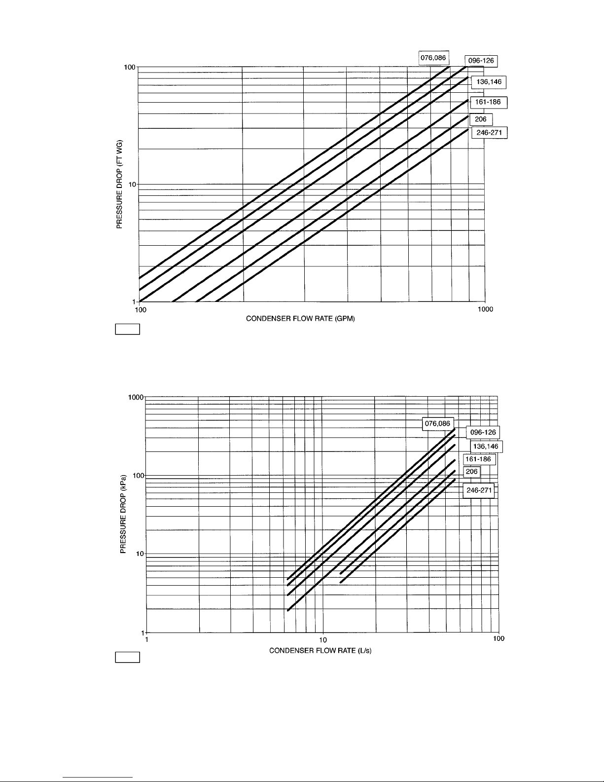
APPENDIX E (cont)
30HX CONDENSER PRESSURE DROP — ENGLISH
Unit Size Range
NOTE: Ft of water = 2.31 x change in psig.
30HX CONDENSER PRESSURE DROP — SI
Unit Size Range
87
Page 88
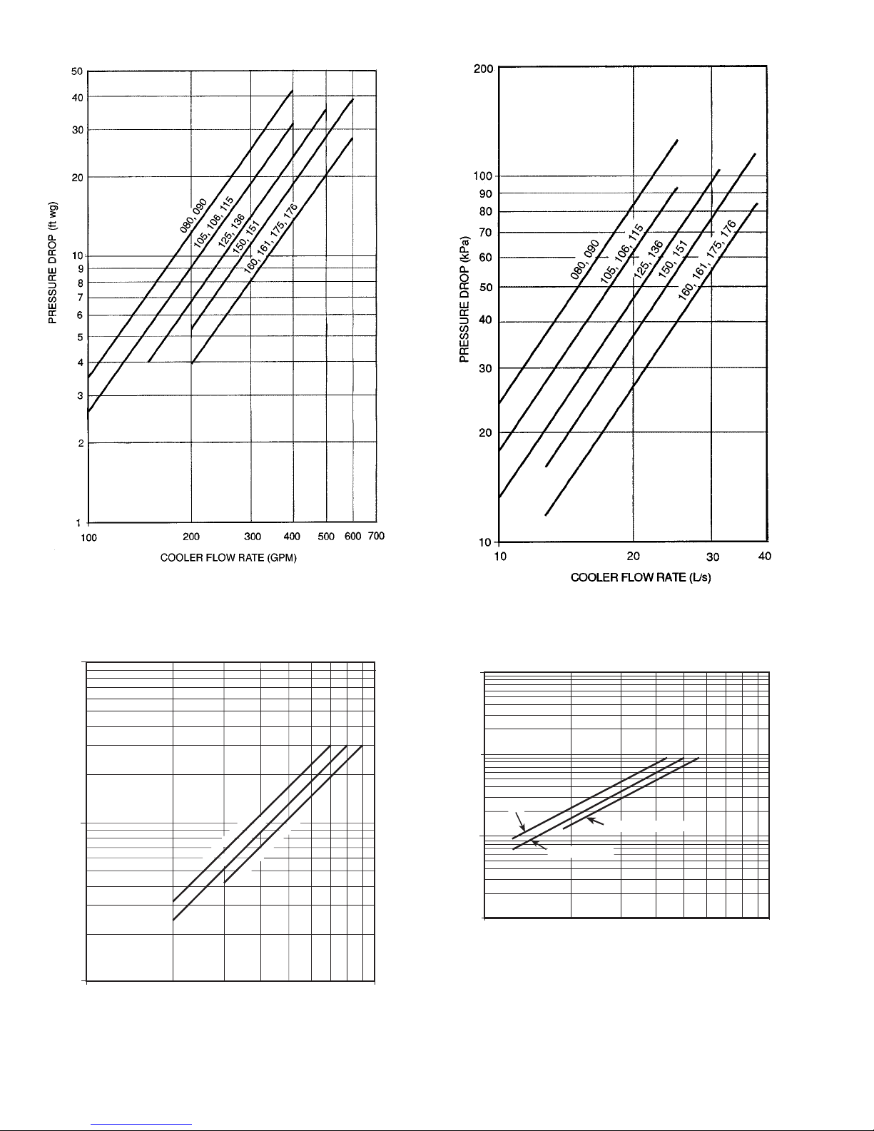
APPENDIX E (cont)
30GX080-176 COOLER PRESSURE DROP —
ENGLISH
NOTE: Ft of water = 2.31 x change in psig.
30GX080-176 COOLER PRESSURE DROP —
SI
100
10
1
100
1000
COOLER FLOW RATE (GPM)
PRESSURE DROP (ft wg)
30GX205, 206
30GX225, 226
30GX250, 251, 265
30GX205-265 COOLER PRESSURE DROP —
ENGLISH
1000
100
10
1
10
100
COOLER FLOW RATE (L/s)
PRESSURE DROP (kpa)
30GX205, 206
30GX225, 226
30GX250, 251, 265
30GX205-265 COOLER PRESSURE DROP —
SI
88
Page 89
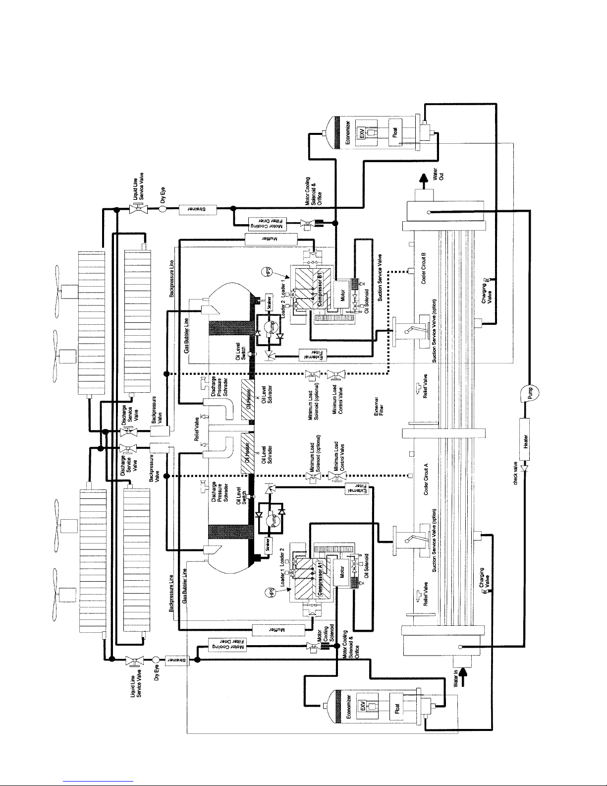
Typical System Components, 30GX, With Economizer
LEGEND
EXV — Electronic Expansion Valve
HPS — High Pressure Switch
APPENDIX F
89
Page 90
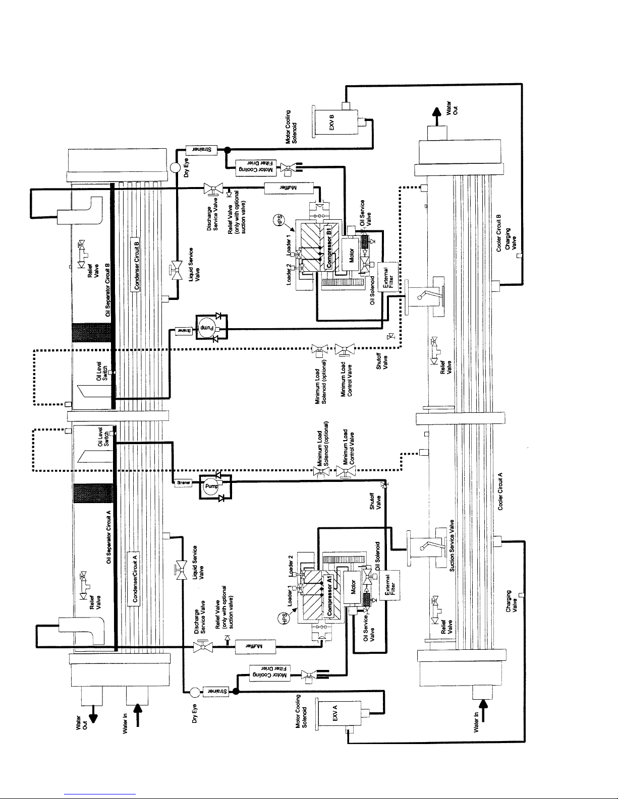
Typical System Components, 30HX, Without Economizer
LEGEND
EXV — Electronic Expansion Valve
HPS — High Pressure Switch
APPENDIX F (cont)
90
Page 91

INDEX
Accessing Functions and Subfunctions, 13
Actual Start-Up, 67
Adjusting PID Routines, 10
Alarms and Alerts, 43
Automatic Default Display, 13
Back Pressure Valve, 4
Burnout Clean-Up Procedure, 58
Capacity Control Overrides, 7
Capacity Control, 6
Capacity Sequence Determination, 7
Carrier Comfort Network (CCN) Interface, 64
Checking Display Codes, 43
Close Control, 7
Coil Cleaning, 53
Complete Unit Stoppage, 43
Compressor Alarm/Alert Circuit, 43
Compressor Changeout Sequence, 56
Compressor Protection Module (CPM), 3, 4
Compressor Protection, 62
Condenser Coils (30GX Only), 53
Condenser Fans (30GX Only), 54
Condenser Pump Control, 12
Control (LOR) Switch, 3
Control Modules, 64
Cooler and Condenser (30HXC) Pump Control, 10
Cooler Heater Control, 13
Cooler Protection, 62
Cooler Pump Control, 10
Demand Limit, 39
Demand Limit, (CCN Loadshed Controlled), 42
DSIO-HV Relay Module, 3, 64
Economizer Operation, 4
Electronic Expansion Device (EXD), 3
Electronic Expansion Device Module, 3
EXD Troubleshooting Procedure, 50
External Temperature Reset, 39
Externally Powered Demand Limit, 42
Externally Powered Reset, 39
EXV Driver Module (DSIO-EXV), 64
EXV Operation, 3
Field Wiring, 68
Filter Drier, 58
Head Pressure Control, 8
High Voltage Relay Module (DSIO-HV), 64, 66
History Function, 25
Inspecting/Cleaning Heat Exchangers, 53
Inspecting/Opening Economizers, 51
Inspecting/Opening Electronic Expansion Valves, 51
Keypad and Display Module (HSIO-II), 3, 13
Lead/Lag Determination, 7
Liquid Line Service Valve, 58
Loading Sequence, 6
Major System Components, 3
Minimum Load Valve, 7
Minutes Left for Start, 6
Minutes Off Time, 6
Moisture-Liquid Indicator, 58
Motor Cooling, 4
Oil Charging/Low Oil Recharging, 55
Oil Filter Maintenance, 56
Oil Pumps, 4
Oil Separator Heaters (30GX), 62
Operating Sequence, 67
Operation Data, 3
Power Failure External to the Unit, 43
Pre-Start-Up Procedure, 67
Pressure Relief Valves, 62
Pressure Transducer Calibration, 59
Pressure Transducers, 59
Processor Module (PSIO-1), 3, 64, 66
PSIO-2 (8052) Module, 3, 64
Refrigerant Charging/Adding Charge, 54
Relief Devices, 62
Replacing Defective Processor Module, 66
Replacing the External Oil Filter, 56
Replacing the Internal Oil Filter, 56
Restart Procedure, 43
Retubing, 52
Return Fluid Temperature Reset, 39
Safety Considerations, 1
Safety Devices, 62
Schedule Function, 37
Sensors, 4
Service Function, 30
Service, 52
Servicing Coolers and Condensers, 52
Set Point Function, 25
Single Circuit Stoppage, 43
Start-Up and Operation, 67
Start-Up Checklist, CL-1
Status Function, 16
System Check, 67
Temperature Reset, 39
Test Function, 25
Thermistor Replacement, 58
Thermistors, 58
Tightening Cooler/Condenser Head Bolts, 52
Troubleshooting, 43
Tube Plugging, 52
Unit Shutoff, 43
Water Treatment, 53
Winter Shutdown Preparation, 66
Wye-Delta vs. Across-the-Line (XL) Starting Option, 5
91
Page 92
SERVICE TRAINING
Packaged Service Training programs are an excellent way to increase your knowledge of the equipment discussed in this manual, including:
• Unit Familiarization
• Installation Overview
• Maintenance
• Operating Sequence
A large selection of product, theory, and skills programs are available, using popular video-based formats and materials. All include video and/or slides, plus companion book.
Classroom Service Training which includes ‘‘hands-on’’ experience with the products in our labs that
can mean increased confidence that really pays dividends in faster troubleshooting and fewer callbacks.
Course descriptions and schedules are in our catalog.
CALL FOR FREE CATALOG 1-800-962-9212
[ ] Packaged Service Training [ ] Classroom Service Training
Copyright 1998 Carrier Corporation
Manufacturer reserves the right to discontinue, or change at any time, specifications or designs without notice and without incurring obligations.
Book 2
Tab5
PC903 CatalogNo.533-062 PrintedinU.S.A.Form30G,H-3TPg92 1099 1-98Replaces:30G,H-2T
Page 93
START-UP CHECKLIST FOR 30GX,HX LIQUID CHILLERS
(Remove and use for job file.)
A. Preliminary Information
JOB NAME
LOCATION
INSTALLING CONTRACTOR
DISTRIBUTOR
START-UP PERFORMED BY
EQUIPMENT:
MODEL
S/N
COMPRESSORS:
CIRCUIT A CIRCUIT B
1) MODEL #
1) MODEL #
S/N S/N
2) MODEL # 2) MODEL #
S/N S/N
COOLER:
MODEL #
S/N
CONDENSER: (30HX ONLY)
MODEL #
S/N
AIR-HANDLING EQUIPMENT:
MANUFACTURER
MODEL # S/N
ADDITIONAL AIR-HANDLING UNITS AND ACCESSORIES
Manufacturer reserves the right to discontinue, or change at any time, specifications or designs without notice and without incurring obligations.
Book 2
Tab 5c
PC 903 Catalog No. 533-062 Printed in U.S.A. Form 30G,H-3T Pg CL-1 1-98 Replaces: 30G,H-2T
Page 94

B. Preliminary Equipment Check
IS THERE ANY SHIPPING DAMAGE? IF SO, WHERE
WILL THIS DAMAGE PREVENT UNIT START-UP?
M UNIT IS LEVEL IN ITS INSTALLATION
M UNIT IS SUPPLIED WITH THE PROPER CONTROL VOLTAGE
VAC
M ELECTRICAL CIRCUIT WIRING HAS BEEN SIZED AND INSTALLED PROPERLY
M UNIT GROUND WIRE HAS BEEN CONNECTED
M ELECTRICAL CIRCUIT PROTECTION HAS BEEN SIZED AND INSTALLED PROPERLY
M ALL TERMINALS ARE TIGHT
M ALL CABLES AND THERMISTORS HAVE BEEN INSPECTED FOR CROSSED WIRES
M ALL PLUG ASSEMBLIES ARE TIGHT
CHECK AIR-HANDLING SYSTEM
M ALL AIR HANDLERS ARE OPERATING
M ALL CHILLED WATER VALVES ARE OPEN
M ALL FLUID PIPING IS CONNECTED PROPERLY
M ALL AIR HAS BEEN VENTED FROM THE SYSTEM
M CHILLED WATER PUMP (CWP) IS OPERATING WITH THE CORRECT ROTATION
CWP AMPERAGE: RATED:
ACTUAL:
PUMP PRESSURES: INLET: OUTLET:
CHECK CONDENSER SYSTEM (30HX ONLY):
M ALL CONDENSER WATER VALVES ARE OPEN
M ALL CONDENSER PIPING IS CONNECTED PROPERLY
ALL AIR HAS BEEN VENTED FROM THE SYSTEM
M CONDENSER WATER PUMP IS OPERATING WITH THE CORRECT ROTATION
CONDENSER WATER PUMP AMP: RATED:
ACTUAL:
PUMP PRESSURES: INLET: OUTLET:
CHECK REMOTE CONDENSER SYSTEM (30HXA ONLY):
M ALL CONDENSER PIPING IS CONNECTED PROPERLY
M CONDENSER LINES/CONDENSER HAS BEEN EVACUATED, AS REQUIRED
CL-2
Page 95
C. Unit Start-Up
M CWP STARTER HAS BEEN PROPERLY INTERLOCKED WITH THE CHILLER
M ALL LIQUID VALVES ARE BACKSEATED
M ALL DISCHARGE VALVES ARE OPEN
M ALL SUCTION VALVES ARE OPEN, IF EQUIPPED
M ALL OIL LINE VALVES ARE OPEN
M UNIT HAS BEEN LEAK CHECKED
LOCATE, REPAIR, AND REPORT ANY REFRIGERANT LEAKS
M CHECK VOLTAGE IMBALANCE: AB AC BC
AVERAGE VOLTAGE = (SEE INSTALLATION INSTRUCTIONS)
MAXIMUM DEVIATION =
(SEE INSTALLATION INSTRUCTIONS)
VOLTAGE IMBALANCE =
(SEE INSTALLATION INSTRUCTIONS)
M VOLTAGE IMBALANCE IS LESS THAN 2%
DO NOT START CHILLER IF VOLTAGE IMBALANCE IS GREATER THAN 2%. CONTACT LOCAL POWER
COMPANY FOR ASSISTANCE.
M ALL INCOMING POWER VOLTAGE IS WITHIN RATED VOLTAGE RANGE
CHECK COMPRESSOR RUNNING CURRENT:
COMPRESSOR NO LOADERS ONE LOADER FULL LOAD
COMP A1,L1
AMPS AMPS AMPS
COMP A1,L2
AMPS AMPS AMPS
COMP A1,L3
AMPS AMPS AMPS
COMP B1,L1
AMPS AMPS AMPS
COMP B1,L2
AMPS AMPS AMPS
COMP B1,L3
AMPS AMPS AMPS
COMP A2,L1
AMPS AMPS AMPS
COMP A2,L2
AMPS AMPS AMPS
COMP A2,L3
AMPS AMPS AMPS
CHECK COOLER WATER LOOP:
WATER LOOP DESIGN VOLUME: GALLONS (LITERS)
CALCULATED VOLUME
GALLONS (LITERS)
3 GALLONS/NOMINAL TON (3.32 LITERS/kW) FOR AIR CONDITIONING
6 GALLONS/NOMINAL TON (6.65 LITERS/kW) FOR PROCESS COOLING
M PROPER LOOP VOLUME ESTABLISHED
M PROPER LOOP CORROSION INHIBITOR INCLUDED
GALLONS (LITERS) OF
M PROPER LOOP FREEZE PROTECTION INCLUDED, IF REQUIRED
GALLONS (LITERS) OF
M PIPING INCLUDES ELECTRIC HEATER TAPE, IF EXPOSED TO THE OUTSIDE
M INLET PIPING TO COOLER INCLUDES A 40 MESH STRAINER
CL-3
Page 96

CHECK PRESSURE DROP ACROSS THE COOLER:
ENTERING COOLER:
PSIG (kPa)
LEAVING COOLER:
PSIG (kPa)
(LEAVING − ENTERING) × 2.31 FT OF H
2
O/PSIG = FT OF H2O
(LEAVING − ENTERING) × 0.334 M OF H
2
O/kPa = MOFH2O
PLOT COOLER PRESSURE DROP ON PERFORMANCE DATA CHART (IN PRODUCT DATA LITERATURE) TO
DETERMINE TOTAL GALLONS/MINUTE (GPM) OR LITERS PER SECOND (L/S) AND FIND UNIT’S MINIMUM
FLOW RATE.
TOTAL GPM (L/S):
GPM/NOMINAL TON (L/S PER TON) =
M TOTAL GPM (L/S) IS GREATER THAN UNIT’S MINIMUM FLOW RATE
M TOTAL GPM (L/S) MEETS JOB SPECIFIED REQUIREMENT OF
GPM (L/S)
M COOLER HEATER FUSE INSTALLED, AND HEATERS ARE ACTIVE (IF USED)
CHECK CONDENSER WATER LOOP:
M PROPER LOOP CORROSION INHIBITOR INCLUDED
GALLONS (LITERS) OF
M INLET PIPING TO CONDENSER INCLUDES A 40 MESH STRAINER
CHECK PRESSURE DROP ACROSS THE CONDENSER (30HXC ONLY):
ENTERING CONDENSER: PSIG (kPa)
LEAVING CONDENSER:
PSIG (kPa)
(LEAVING − ENTERING) × 2.31 FT OF H
2
O= FT OF H2O
(LEAVING − ENTERING) × 0.334 M OF H
2
O/kPa = MOFH2O
PLOT CONDENSER PRESSURE DROP ON PERFORMANCE DATACHART (IN PRODUCT DATALITERATURE) TO
DETERMINE TOTAL GALLONS/MINUTE (GPM) OR LITERS PER SECOND (L/S) AND FIND UNIT’S MINIMUM
FLOW RATE.
TOTAL GPM (L/S):
GPM/NOMINAL TON (L/S PER TON) =
M TOTAL CONDENSER GPM (L/S) IS GREATER THAN UNIT’S MINIMUM FLOW RATE
M TOTAL GPM MEETS JOB SPECIFIED REQUIREMENT OF
GPM (L/S)
CL-4
Page 97

PERFORM TEST FUNCTION (INDICATE POSITIVE RESULT):
ONCE POWER IS SUPPLIED TO THE UNIT, CHECK THE DISPLAY FOR ANY ALARMS, SUCH AS PHASE REVERSAL. FOLLOW THE TEST FUNCTION INSTRUCTIONS IN THE CONTROLS AND TROUBLESHOOTING LITERATURE. BE SURE TO CHECK FOR PROPER FAN ROTATION WITH THE FAN TEST SECTIONS. BE SURE ALL SERVICE VALVES ARE OPEN BEFORE BEGINNING THE COMPRESSOR TEST SECTION. ITEMS MARKED WITH ‘‘†’’
CAN BE TESTED ONLY IF THE UNIT IS CONFIGURED FOR THIS OPTION. DO NOT RUN OIL PUMPS FOR MORE
THAN 20 SECONDS.
M LOADER A1 M LOADER B1
M LOADER A2 M LOADER B2
M MINIMUM LOAD VALVE A† M MINIMUM LOAD VALVE B†
M CIRCUIT A OIL HEATER M CIRCUIT B OIL HEATER
M A1 MOTOR COOLING SOLENOID M B1 MOTOR COOLING SOLENOID
M A2 MOTOR COOLING SOLENOID† M B2 MOTOR COOLING SOLENOID†
M CIRCUIT A OIL PUMP M CIRCUIT B OIL PUMP
M OIL SOLENOID A1 M OIL SOLENOID B1
M OIL SOLENOID A2† M OIL SOLENOID B2†
M CIRCUIT A EXV M FAN 1 (30GX)†
M CIRCUIT B EXV M FAN 2 (30GX)†
M CIRCUIT A WATER VALVE† M FAN 3 (30GX)†
M CIRCUIT A% FAN SPEED (GX)† M FAN 4 (30GX)†
M CIRCUIT B% FAN SPEED (GX)† M FAN 5 (30GX)†
M FAN 6 (30GX)†
M COOLER PUMP†
M COMPRESSOR A1 M CONDENSER PUMP†
M COMPRESSOR A2† M COOLER HEATER†
M COMPRESSOR B1 M ALARM RELAY†
M COMPRESSOR B2†
M CHECK FOR COMMUNICATING MODULES (BLINKING RED AND GREED LEDs)
M CORRECT FLUID SET POINTS ARE ENTERED
COOL SET POINT 1
COOL SET POINT 2
M CORRECT DATE, TIME, AND OPERATING SCHEDULE(S) ARE SET
CL-5
Page 98
M REVIEW AND RECORD FACTORY CONFIGURATION CODES,
CONFIGURATION CODE 1:
CONFIGURATION CODE 2:
CONFIGURATION CODE 3:
CONFIGURATION CODE 4:
CONFIGURATION CODE 5:
M REVIEW AND RECORD SOFTWARE VERSION,
SOFTWARE CESR500100 VERSION
M REVIEW AND RECORD FIELD CONFIGURATION,
COOLER FLUID SELECT
MIN LOAD VALVE SELECT
LOADING SEQ. SELECT
LEAD/LAG SEQ. SELECT
HEAD PRESSURE CONTROL
MOTORMASTER SELECT
WATER VALVE TYPE
EXTERNAL RESET SENSOR
COOLER PUMP INTERLOCK
COOLER PUMP CONTROL
CONDENSER PUMP CONTROL
CONDENSER FLOW SWITCH
CONDENSER WATER SENSORS
TO START THE CHILLER:
BE SURE THAT ALL SERVICE VALVESARE OPEN, AND ALL PUMPS ARE ON BEFORE ATTEMPTING TO START
THIS MACHINE. ONCE ALL CHECKS HAVE BEEN MADE, MOVE THE SWITCH TO ‘‘LOCAL’’ OR ‘‘REMOTE’’
FROM ‘‘STOP.’’
M UNIT STARTS AND OPERATES PROPERLY.
TEMPERATURES AND PRESSURES:
ONCE THE MACHINE HAS BEEN OPERATING FOR AWHILEAND THE TEMPERATURES AND PRESSURES HAVE
STABLIZED, RECORD THE FOLLOWING:
COOLER EWT
COOLER LWT
AMBIENT TEMPERATURE
CONDENSER EWT
(ENTERING WATER TEMP)
CONDENSER LWT
(LEAVING WATER TEMP)
CIR. A OIL PRESS
CIR. A SUCTION PRESS
CIR. A DISCHARGE PRESS
CIR. A DISCHARGE TEMP
CIR. A LIQUID LINE TEMP
CIR. B OIL PRESS
CIR. B SUCTION PRESS
CIR. B DISCHARGE PRESS
CIR. B DISCHARGE TEMP
CIR. B LIQUID LINE TEMP
NOTE: OIL FILTER PRESSURE DROPS MUST BE CHECKED AFTER INITIAL 200-300 HOURS OF COMPRESSOR
OPERATION. SEE OIL FILTER MAINTENANCE SECTION, PAGE 56.
CL-6
Page 99

NOTES:
CL-7
Page 100

Copyright 1998 Carrier Corporation
Manufacturer reserves the right to discontinue, or change at any time, specifications or designs without notice and without incurring obligations.
Book 2
Tab 5c
PC903 CatalogNo.533-062 PrintedinU.S.A. Form30G,H-3T PgCL-8 1099 1-98 Replaces:30G,H-2T
 Loading...