

Page 1
30HXA,HXC076-186
Water-Cooled and Condenserless Chillers
Installation Instructions
50/60 Hz
CONTENTS
Page
SAFETY CONSIDERATIONS ...................1
INTRODUCTION ..............................1
INSTALLATION .............................1-27
Step 1 — Inspect Shipment ...................1
Step 2 — Rig and Place Unit ..................1
Step 3 — Piping Connections .................9
• COOLER FLUID, VENT, AND DRAIN
• BRINE UNITS
• PREPARATION FOR YEAR-ROUND
OPERATION
• 30HXA REFRIGERANT PIPING
• 30HXC CONDENSER CONNECTIONS
• INSTALL PRESSURE RELIEF REFRIGERANT
VENT PIPING
Step 4 — Make Electrical Connections .......14
• FIELD POWER CONNECTIONS
• FIELD CONTROL POWER CONNECTIONS
Step 5 — Install Accessories ................26
• ELECTRICAL
• 30HXA LOW-AMBIENT OPERATION
• MINIMUM LOAD ACCESSORY
• MISCELLANEOUS ACCESSORIES
Step 6 — Leak Test Unit .....................26
• 30HXC UNITS
• 30HXA UNITS
Step 7 — Refrigerant Charge ................26
• 30HXC UNITS
• 30HXA UNITS
IMPORTANT:This equipment generates, uses, and can
radiate radio frequency energy. If not installed and
used in accordance with these instructions, this equipment may cause radio interference.The equipment has
been tested and found to comply with the limits of a
Class A computing device as defined by the FCC
(Federal Communications Commission, U.S.A.) Regulations, Subpart J of Part 15, which are designed to
provide reasonable protection against such interference when operated in a commercial environment.
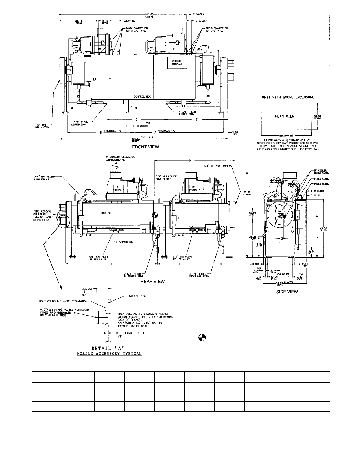
INSTALLATION
Step 1— Inspect Shipment —
age upon arrival. If damage is found, file a claim with the
shipping company right away. Do not store units in an area
exposed to weather because of sensitive control mechanisms and electronic devices.
Locate unit indoors. When considering unit location, consult National Electrical Code (NEC, U.S.A.) and local code
requirements. Allow sufficient space for wiring, piping, and
service. Install unit in an area which will not be exposed to
subfreezing weather. See Fig. 1-4 for clearance details.
Allow the following clearances for service access:
Front .............................. 3ft(914 mm)
Rear ............................... 3ft(914 mm)
Top ............................... 2ft(610 mm)
Ends ............... tube removal at one (either) end;
3 ft (914 mm) at opposite end.
Inspect unit for dam-
SAFETY CONSIDERATIONS
Installing, starting up, and servicing this equipment can
be hazardous due to system pressures, electrical components, and equipment location. Only trained, qualified
installers and service mechanics should install, start up, and
service this equipment.
When working on the equipment, observe precautions in
the literature, andontags, stickers, and labels attached to the
equipment.
• Follow all safety codes.
• Wear safety glasses and work gloves.
• Use care in handling, rigging, and setting bulky
equipment.
INTRODUCTION
These instructions cover installation of 30HX liquid chillers with electronic controls and units with factory-installed
options (FIOPSs).
Manufacturer reserves the right to discontinue, or change at any time, specifications or designs without notice and without incurring obligations.
Book 2
Tab 5c
PC 903 Catalog No. 563-052 Printed in U.S.A. Form 30HX-1SI Pg 1 5-96 Replaces: New
Be sure surface beneath the unit is level and is capable of
supporting the operating weight of the unit. See Fig. 5 and
Tables 1A and 1B for unit operating weights. If necessary,
add supporting structure (steel beams or reinforced concrete
slabs) to floor to transfer weight to nearest beams.
Step 2 — Rig and Place Unit
Rig unit from the top heat exchanger only. Rigging from
the bottom heat exchanger will cause the unit to be lifted
unsafely. Personal injury or damage to the unit may
occur.
Do not remove unit from skid until unit is in its
final location. Rig from the rigging holes provided in the top
heat exchanger. See Fig. 1-5 for rigging and center of gravity information. Lower the unit carefully onto the floor or
roller. Push or pull only on the skid, not the unit. If the
unit is moved on rollers, use a minimum of 3 evenly-spaced
rollers.
Copy continued on page 9.
Page 2
LEGEND
K.O. — Knockout
THK — Thick
TYP — Typical
UNIT
30HXC
076
086
096
106
116
126
136
146
NOTES:
1. Denotes center of gravity.
2. Dimensions are in inches. Dimensions ( ) are in millimeters.
3. Recommended service clearance around unit (front, back, and one side) is
369 (914).
DIMENSIONS — in. (mm)
ABCDEFGHJK LMNP
102.12
(2594)
102.12
(2594)
102.12
(2594)
102.12
(2594)
132.56
(3367)
132.56
(3367)
132.56
(3367)
132.56
(3367)
45.87
(1165)
45.87
(1165)
37.63
(956)
37.63
(956)
72.12
(1832)
72.12
(1832)
72.12
(1832)
72.12
(1832)
45.87
(1165)
45.87
(1165)
54.12
(1375)
54.12
(1375)
50.63
(1286)
50.63
(1286)
50.63
(1286)
50.63
(1286)
9.87
(251)
9.87
(251)
9.87
(251)
10.47
(266)
9.87
(251)
9.87
(251)
9.87
(251)
9.87
(251)
9.36
(236)
9.36
(236)
9.36
(236)
10.28
(261)
9.36
(236)
9.36
(236)
9.36
(236)
9.36
(236)
43.50
(1105)
43.50
(1105)
43.50
(1105)
45.50
(1156)
43.50
(1105)
43.50
(1105)
43.50
(1105)
43.50
(1105)
15.60
(396)
15.60
(396)
15.60
(396)
15.60
(396)
31.11
(790)
31.11
(790)
31.11
(790)
31.11
(790)
85.15
(2163)
85.15
(2163)
85.15
(2163)
85.15
(2163)
100.66
(2557)
100.66
(2557)
100.66
(2557)
100.66
(2557)
4.00
(102)
4.00
(102)
4.00
(102)
5.00
(127)
4.00
(102)
4.00
(102)
4.00
(102)
4.00
(102)
95.00
(2413)
95.00
(2413)
95.00
(2413)
95.00
(2413)
126.00
(3200)
126.00
(3200)
126.00
(3200)
126.00
(3200)
65.22
(1657)
65.22
(1657)
65.22
(1657)
67.22
(1707)
65.22
(1657)
65.22
(1657)
65.22
(1657)
65.22
(1657)
1.90
(48)
1.90
(48)
1.90
(48)
1.90
(48)
1.70
(43)
1.70
(43)
1.70
(43)
1.70
(43)
47.00
(1194)
47.00
(1194)
47.00
(1194)
47.00
(1194)
62.20
(1580)
62.20
(1580)
62.20
(1580)
62.20
(1580)
30.80
(782)
30.80
(782)
30.80
(782)
30.80
(782)
29.40
(747)
29.40
(747)
29.40
(747)
29.40
(747)
Fig. 1 — Base Unit Dimensions, 30HXC076-146 Units
2
Page 3
UNIT
30HXC
161
171
186
DIMENSIONS — in. (mm)
ABCD E
72.12
(1832)
61.37
(1559)
61.37
(1559)
50.63
(1286)
61.37
(1559)
61.37
(1559)
2.00
(51)
2.00
(51)
2.00
(51)
63.50
(1588)
63.50
(1588)
63.50
(1588)
31.00
(787)
31.00
(787)
31.00
(787)
Fig. 2 — Base Unit Dimensions, 30HXC161-186 Units
NOTES:
1. Denotes center of gravity.
2. Dimensions are in inches. Dimensions ( ) are in millimeters.
3. Recommended service clearance around unit (front, back, and one side) is
369 (914).
LEGEND
K.O. — Knockout
THK — Thick
TYP — Typical
3
Page 4
LEGEND
K.O. — Knockout
SAE — Society of Automotive
THK — Thick
TYP — Typical
Engineers, U.S.A.
UNIT
30HXA
076
086
096
106
116
126
136
146
NOTES:
1. Denotes center of gravity.
2. Dimensions are in inches. Dimensions ( ) are in millimeters.
3. Recommended service clearance around unit (front, back, and one side) is
369 (914).
DIMENSIONS — in. (mm)
ABCDEFGHJKLMNPRSTUV
102.12
45.87
45.87
27.81
9.36
43.50
15.60
85.15
4.00
95.00
65.22
13.93
59.48
5.72
45.81
46.25
2.40
46.40
(2594)
102.12
(2594)
102.12
(2594)
102.12
(2594)
132.56
(3367)
132.56
(3367)
132.56
(3367)
132.56
(3367)
(1165)
45.87
(1165)
37.63
(956)
37.63
(956)
72.12
(1832)
72.12
(1832)
72.12
(1832)
72.12
(1832)
(1165)
45.87
(1165)
54.12
(1375)
54.12
(1375)
50.63
(1286)
50.63
(1286)
50.63
(1286)
50.63
(1286)
(706)
27.81
(706)
27.81
(706)
28.41
(721)
27.81
(706)
27.81
(706)
27.81
(706)
27.81
(706)
(236)
9.36
(236)
9.36
(236)
10.28
(261)
9.36
(236)
9.36
(236)
9.36
(236)
9.36
(236)
(1105)
43.50
(1105)
43.50
(1105)
45.50
(1156)
43.50
(1105)
43.50
(1105)
43.50
(1105)
43.50
(1105)
(396)
15.60
(396)
15.60
(396)
15.60
(396)
31.11
(790)
31.11
(790)
31.11
(790)
31.11
(790)
(2163)
85.15
(2163)
85.15
(2163)
85.15
(2163)
100.66
(2557)
100.66
(2557)
100.66
(2557)
100.66
(2557)
(102)
4.00
(102)
4.00
(102)
5.00
(127)
4.00
(102)
4.00
(102)
4.00
(102)
4.00
(102)
(2413)
95.00
(2413)
95.00
(2413)
95.00
(2413)
126.00
(3200)
126.00
(3200)
126.00
(3200)
126.00
(3200)
(1657)
65.22
(1657)
65.22
(1657)
67.22
(1707)
65.22
(1657)
65.22
(1657)
65.22
(1657)
65.22
(1657)
(354)
13.93
(354)
22.15
(563)
22.15
(563)
40.16
(1020)
40.16
(1020)
40.16
(1020)
40.16
(1020)
(1511)
59.48
(1511)
42.77
(1086)
42.77
(1086)
64.23
(1631)
64.23
(1631)
64.23
(1631)
64.23
(1631)
(145 )
5.72
(145)
5.72
(145)
5.87
(149)
5.72
(145)
5.72
(145)
5.72
(145)
5.72
(145)
(1164)
45.81
(1164)
54.06
(1373)
54.06
(1373)
72.06
(1830)
72.06
(1830)
72.06
(1830)
72.06
(1830)
(1175)
46.25
(1175)
38.00
(965)
38.00
(965)
51.01
(1296)
51.01
(1296)
51.01
(1296)
51.01
(1296)
(61)
2.40
(61)
2.40
(61)
2.40
(61)
2.30
(58)
2.30
(58)
2.30
(58)
2.30
(58)
(1179)
46.40
(1179)
46.40
(1179)
46.40
(1179)
61.00
(1549)
61.00
(1549)
61.00
(1549)
61.00
(1549)
35.00
(889)
35.00
(889)
35.00
(889)
35.00
(889)
34.30
(871)
34.30
(871)
34.30
(871)
34.30
(871)
Fig. 3 — Base Unit Dimensions, 30HXA076-146 Units
4
Page 5
LEGEND
K.O. — Knockout
SAE — Society of Automotive
THK — Thick
TYP — Typical
Engineers, U.S.A.
UNIT
30HXA
161
171
186
NOTES:
1. Denotes center of gravity.
2. Dimensions are in inches. Dimensions ( ) are in millimeters.
3. Recommended service clearance around unit (front, back, and one side) is
369 (914).
DIMENSIONS — in. (mm)
ABCDEFGHJ
72.12
(1832)
61.37
(1559)
61.37
(1559)
50.63
(1386)
61.37
(1559)
61.37
(1559)
48.56
(1233)
43.25
(1099)
43.25
(1099)
46.62
(1184)
46.62
(1184)
46.62
(1184)
72.06
(1830)
61.31
(1572)
61.31
(1572)
51.00
(1295)
61.75
(1568)
61.75
(1568)
2.70
(69)
2.70
(69)
2.70
(69)
62.50
(1588)
62.50
(1588)
62.50
(1588)
35.20
(894)
35.20
(894)
35.20
(894)
Fig. 4 — Base Unit Dimensions, 30HXA161-186 Units
5
Page 6
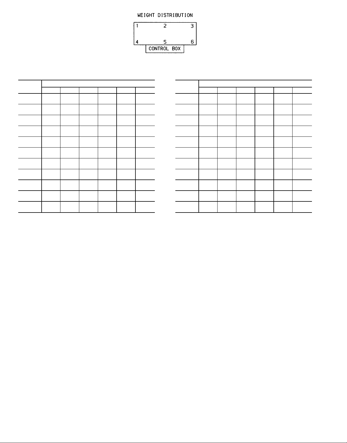
WEIGHT DISTRIBUTION AT EACH MOUNTING PLATE,
30HXC UNITS — Lb (Kg)
UNIT
30HXC
076
086
096
106
116
126
136
146
161
171
186
NOTE: See Fig. 1-4 for center of gravity details.
123456
738
(335)
738
(335)
686
(311)
730
(331)
728
(330)
738
(335)
758
(344)
763
(346)
817
(371)
936
(425)
962
(436)
MOUNTING PLATE NO.
943
(428)
947
(430)
968
(439)
1028
(466)
1114
(505)
1127
(511)
1176
(533)
1182
(536)
1272
(577)
1318
(598)
1361
(617)
595
(270)
597
(271)
693
(314)
744
(337)
777
(352)
780
(354)
811
(368)
815
(370)
908
(412)
840
(381)
860
(390)
1110
(503)
1112
(504)
1027
(466)
1073
(487)
1053
(478)
1061
(481)
1083
(491)
1085
(492)
1219
(553)
1379
(626)
1410
(640)
1418
(643)
1427
(647)
1447
(656)
1510
(685)
1615
(733)
1628
(738)
1689
(766)
1697
(770)
1890
(857)
1946
(883)
1996
(905)
(406)
(409)
1034
(469)
1092
(495)
1127
(511)
1131
(513)
1171
(531)
1172
(532)
1346
(610)
1241
(563)
1265
(574)
Fig. 5 — Rigging Information
896
902
WEIGHT DISTRIBUTION AT EACH MOUNTING PLATE,
30HXA UNITS — Lb (Kg)
UNIT
30HXA
076
086
096
106
116
126
136
146
161
171
186
123456
555
(252)
555
(252)
509
(231)
555
(252)
530
(240)
540
(245)
548
(249)
551
(250)
560
(254)
627
(284)
648
(294)
MOUNTING PLATE NO.
793
(360)
798
(362)
808
(367)
869
(394)
895
(406)
905
(410)
926
(420)
930
(422)
965
(438)
968
(439)
1004
(455)
418
(190)
418
(190)
493
(224)
541
(245)
540
(245)
541
(245)
555
(252)
555
(252)
598
(271)
534
(242)
552
(250)
926
(420)
928
(421)
848
(385)
896
(406)
855
(388)
864
(392)
8743
(396)
883
(400)
954
(433)
1072
(486)
1110
(504)
1326
(601)
1340
(608)
1350
(612)
1410
(640)
1456
(660)
1468
(666)
1498
(679)
1506
(683)
1650
(748)
1658
(752)
1703
(772)
699
(317)
705
(320)
827
(375)
880
(399)
887
(402)
887
(402)
908
(412)
908
(412)
1025
(465)
918
(416)
939
(426)
6
Page 7
Table 1A — Physical Data, English
UNIT SIZE 076 086 096 106 116 126 136 146 161 171 186
UNIT WEIGHT (lb)
Fluid Cooled (HXC) 5700 5723 5855 6177 6415 6465 6688 6718 7452 7660 7854
Condenserless (HXA) 4717 4744 4835 5151 5162 5205 5308 5333 5752 5777 5946
COMPRESSORS Semi-Hermetic, Twin Screw
Quantity 222222 2 2 2 2 2
Nominal Capacity per
Compressor (tons)
Economizer No No No No No No No No Yes Yes Yes
No. Capacity Steps
Standard 666666 6 6 6 6 6
Optional (maximum) 888888 8 8 8 8 8
Minimum Step Capacity (%)
Standard 20 20 20 20 20 20 20 20 20 20 20
Optional 10 10 10 10 10 10 10 10 10 10 10
REFRIGERANT TYPE R-134a
Charge* (lb)
Circuit A/Circuit B
COOLER TYPE Shell and Tube with Enhanced Copper Tubes
Part No. 10HX400− 001 001 002 010 007 007 006 006 104 012 013
Net Fluid Volume (gal) 17.0 17.0 19.0 22.6 21.4 21.4 24.0 24.0 28.5 28.5 33.4
Maximum Refrigerant Pressure
(psig)
Maximum Fluid-Side Pressure
(psig)
Fluid Connections (in.) Steel Weld Couplings
Inlet and Outlet 444544 4 4 5 5 5
Drain (NPT)
30HXA OIL SEPARATOR
Part No. 09RX400− 007 007 008 008 009 009 009 009 009 010 010
Maximum Refrigerant Pressure
(psig)
Refrigerant Connections (in.)
Discharge 2
Liquid 11⁄
CONDENSER (HXC) Shell and Tube with Enhanced Copper Tubes
Part No. 09RX400− 001 001 002 002 003 003 004 004 005 006 006
Net Fluid Volume (gal) 16.8 16.8 18.3 18.3 23.9 23.9 27.5 27.5 30.6 37.6 37.6
Maximum Refrigerant Pressure
(psig)
Maximum Water-Side Pressure
(psig)
Water Connections (in.) Steel Weld Couplings
Inlet and Outlet 555555 5 5 5 5 5
Drain (NPT)
*Charges listed are for 30HXC units. The 30HXA units are shipped with a holding charge only.
39/39 46/39 56/39 66/39 66/46 66/56 80/56 80/66 80/56 66/80 80/80
55/55 66/55 79/55 95/55 95/66 95/79 114/79 114/95 130/90 109/130 130/130
220 220 220 220 220 220 220 220 220 220 220
300 300 300 300 300 300 300 300 300 300 300
1
1
⁄
2
1
⁄
2
1
⁄
2
1
⁄
2
1
⁄
2
⁄
1
2
⁄
2
1
⁄
2
1
⁄
2
1
⁄
2
320 320 320 320 320 320 320 320 320 320 320
1
⁄
8
21⁄
8
21⁄
8
21⁄
8
21⁄
8
21⁄
8
21⁄
8
21⁄
8
21⁄
8
21⁄
8
11⁄
8
11⁄
8
11⁄
8
11⁄
8
11⁄
8
11⁄
8
11⁄
8
13⁄
8
13⁄
8
8
220 220 220 220 220 220 220 220 220 220 220
300 300 300 300 300 300 300 300 300 300 300
1
1
⁄
2
1
⁄
2
1
⁄
2
1
⁄
2
1
⁄
2
⁄
1
2
⁄
2
1
⁄
2
1
⁄
2
1
⁄
2
21⁄
13⁄
1
⁄
2
8
8
1
⁄
2
7
Page 8
Table 1B — Physical Data, SI
UNIT SIZE 076 086 096 106 116 126 136 146 161 171 186
UNIT WEIGHT (Kg)
Fluid Cooled (HXC) 2586 2596 2656 2802 2910 2933 3034 3047 3380 3476 3563
Condenserless (HXA) 2140 2152 2193 2336 2341 2361 2408 2419 2609 2620 2697
COMPRESSORS Semi-Hermetic, Twin Screw
Quantity 22222222222
Nominal Capacity per
Compressor (kW)
Economizer No No No No No No No No Yes Yes Yes
No. Capacity Steps
Standard 66666666666
Optional (maximum) 88888888888
Minimum Step Capacity (%)
Standard 20 20 20 20 20 20 20 20 20 20 20
Optional 10 10 10 10 10 10 10 10 10 10 10
REFRIGERANT TYPE R-134a
Charge* (Kg)
Circuit A/Circuit B
COOLER TYPE Shell and Tube with Enhanced Copper Tubes
Part No. 10HX400− 001 001 002 010 007 007 006 006 104 012 013
Net Fluid Volume (L) 64.3 64.3 71.9 85.5 81.0 81.0 90.8 90.8 107.9 107.9 126.4
Maximum Refrigerant
Pressure (kPa)
Maximum Fluid-Side
Pressure (kPa)
Fluid Connections (in.) Steel Weld Couplings
Inlet and Outlet 44454444555
Drain (NPT)
30HXA OIL SEPARATOR
Part No. 09RX400− 007 007 008 008 009 009 009 009 009 010 010
Maximum Refrigerant
Pressure (kPa)
Refrigerant Connections (in.)
Discharge 2
Liquid 11⁄
CONDENSER (HXC) Shell and Tube with Enhanced Copper Tubes
Part No. 09RX400− 001 001 002 002 003 003 004 004 105 006 006
Net Fluid Volume (L) 63.6 63.6 69.3 69.3 90.5 90.5 104.1 104.1 115.8 142.3 142.3
Maximum Refrigerant
Pressure (kPa)
Maximum Water-Side
Pressure (kPa)
Water Connections (in.) Steel Weld Couplings
Inlet and Outlet 55555555555
Drain (NPT)
*Charges listed are for 30HXC units. The 30HXA units are shipped with a holding charge only.
137/137 162/137 197/137 232/137 232/137 232/197 281/197 281/232 281/197 232/281 281/281
24.9/
24.9
29.9/
24.9
35.8/
24.9
43.1/
24.9
43.1/
29.9
43.1/
35.8
51.7/
35.8
51.7/
43.1
59.0/
40.8
49.4/
59.0
59.0/
59.0
1517 1517 1517 1517 1517 1517 1517 1517 1517 1517 1517
2068 2068 2068 2068 2068 2068 2068 2068 2068 2068 2068
1
⁄
2
1
⁄
2
1
⁄
2
1
⁄
2
1
⁄
2
1
⁄
2
1
⁄
2
1
⁄
2
1
⁄
2
1
⁄
2
1
⁄
2
2205 2205 2205 2205 2205 2205 2205 2205 2205 2205 2205
1
⁄
8
21⁄
8
21⁄
8
21⁄
8
21⁄
8
21⁄
8
21⁄
8
21⁄
8
21⁄
8
21⁄
8
8
11⁄
8
11⁄
8
11⁄
8
11⁄
8
11⁄
8
11⁄
8
11⁄
8
13⁄
8
13⁄
21⁄
8
13⁄
1517 1517 1517 1517 1517 1517 1517 1517 1517 1517 1517
2068 2068 2068 2068 2068 2068 2068 2068 2068 2068 2068
1
⁄
2
1
⁄
2
1
⁄
2
1
⁄
2
1
⁄
2
1
⁄
2
1
⁄
2
1
⁄
2
1
⁄
2
1
⁄
2
1
⁄
2
8
8
8
Page 9
IMPORTANT: Some of the unit skids are larger than
standard door openings. Be sure that the path to the
unit’s final destination is wide enough to accommodate unit shipping skid. Remove the skid if necessary.
If skid is removed and rollers are used, attach rollers
to unit tube sheets while moving unit.
Areas where unit mounting points will be located must be
level to within1⁄16in. per ft (1 mm per m) along the long
axis of the unit. Once unit is in place and level, bolt unit to
the floor. Use isolation pads under the unit to aid in vibration
isolation as required.
Step 3 — Piping Connections — See Fig. 6 and
7 for typical piping applications.
COOLER FLUID, VENT, AND DRAIN — The inlet (re-
turn) fluid connection is always the lower of the 2 cooler
connections. See Fig. 6 for locations. A screen strainer with
a minimum of 20 mesh should be installed ahead of the cooler
inlet to prevent debris from damaging internal tubes of the
cooler. Outlet (supply) fluid connection is the upper connection of the 2 cooler connections.
The cooler has weld flanges to connect the field-supplied
piping. Plan the piping arrangement in accordance with good
piping practices and so that the piping does not cross in front
of the cooler head. Use flexible connections on cooler piping to reduce vibration transmission. Offsetthe piping to permit removal of the cooler head for maintenance. Install pipe
hangers where needed. Make sure no weight or stress is placed
on the water nozzle.
To install cooler piping:
1. Remove bolts on weld flanges, and remove flanges from
cooler fluid heads.
Remove the weld flanges before welding piping to
the flanges. Refer to Fig. 1-4 for weld flange locations. Failure to remove the flanges may damage the
sensors and insulation.
2. To keep debris from entering the heat exchanger during
shipping and storage, the gaskets between the weld flanges
and the fluid heads do not have holes cut into them. The
gaskets have perforations where the holes are to be cut.
Carefully cut a hole along the designated perforations.
IMPORTANT: Be sure to remove flanges and cut
holes in the gaskets between the flanges and the fluid
heads as indicated.
3. Apply a thin coat of oil to both sides of each gasket to
help ensure a good seal, and reattach each gasket to each
fluid head.
4. Weld the field-supplied piping to the weld flanges.
5. Bolt the weld flanges back onto their respective fluid heads.
IMPORTANT:When bolting the weld flanges to the
fluid heads, be sure to locate the flange such that
the hole in each flange lines up completely with the
hole in each fluid head. If installed incorrectly, part
of the hole in the fluid head will be blocked off.
This will result in impaired fluid flow in high pressure drop applications.
Tighten all cooler head bolts to 250 ft-lb (339 N-m)
before filling system with water (or brine).
6. Install field-supplied differentialflow switches in the cooler
piping for protection against loss of flow. The differential
flow switches must be installed on top of the pipe in a
horizontal run and should be at least 5 pipe diameters from
any bend. Install the low-pressure differential flow switch
into the outlet line piping, and install the high-pressure
differentialflow switch into the inlet line piping as shown
in Fig. 8.
7. Provide openings in fluid piping for pressure gages and
thermometers (if used). These openings should be 5 to 10
pipe diameters from the unit water nozzles. For thorough
mixing and temperature stabilization, wells in the leaving fluid pipe should extend at least 2 in. (50 mm) into
the pipe.
Accessory Victaulic-type connections are available. Fol-
low the connection directions provided with the accessory.
Although cooler has an air vent, it is recommended that a
field-supplied air vent be installed in the system to facilitate
servicing. Field-supplied shut-offand balancing valves should
also be installed to facilitate servicing and flow balancing.
Locate valves in return and supply fluid lines as close to the
chiller as possible. Locate air vent at highest point of the
cooler fluid system. See Fig. 6.
Provide drain connections at all low points to permit complete drainage of the system.
BRINE UNITS — Special factory modifications to the units
are required to allow them to operate at fluid temperatures
less than 34 F (1.1 C). Be sure that the fluid has sufficient
inhibited ethylene glycol or other suitable corrosionresistant antifreeze solution to prevent cooler freeze up.
PREPARATIONFOR YEAR-ROUND OPERATION — In
areas where the piping or unit is exposed to 32 F (0 °C) or
lower ambient temperatures, freeze-up protection is recommended using inhibited ethylene glycol or other suitable
corrosion-resistant antifreeze solution and electric heater tapes.
Heater tapes should have a rating for area ambient temperatures and be covered with a suitable thickness of closed-cell
insulation. Route power for the heater tapes from a separatelyfused disconnect. Mount the disconnect within sight from
the unit per local or NEC codes. Identify disconnect as heater
tape power source with warning that power must not be turned
off except when servicing unit.
Fill the fluid loop with water (or brine) and a corrosionresistant inhibitor suitable for the water of the area. Consult
the local water authority for characteristics of area water and
a recommended inhibitor for the cooler fluid loop. It is recommended that once the cooler water lines have been
installed and leak checked that the cooler heads be insulated
with a suitable thickness of closed-cell insulation. This will
minimize the amount of condensation that will form on the
cooler heads.
IMPORTANT: Before starting the unit, be sure all of
the air has been purged from the system.
A drain connection is located at the bottom of the cooler
head. See Fig. 3 and 4 for connection location. Install shutoffvalves to the drain line before filling the system with fluid.
9
Page 10

intended to show details for specific installation. Certified field wiring and
NOTES:
1. Wiring and piping shown are for general point-of-connection only and are not
dimensional diagrams are available upon request. The 30HXA and HXC units
should be installed using certified drawings.
2. All wiring must comply with applicable codes.
LEGEND
lation are all field supplied.
3. Refer to Carrier System Design Manual for details regarding piping techniques.
4. Piping, wiring, switches, valves, vent, gages, strainers, drain, and vibration iso-
Field Wiring
Field Piping
Fig.6—Typical Cooler (30HXA, HXC) and Condenser (30HXC Only) Piping and Wiring
10
Page 11

NOTES:
1. Piping shown is for general point-of-connection only and is not intended to show details for a specific installation. Certified field wiringanddimensional drawings are available upon request. The 30HXA
units should be installed using certified drawings.
2. Refer to Carrier System Design Manual for details regarding piping techniques.
3. Piping and pressure relief devices are field supplied.
4. Vent pipes properly per local codes.
TO REMOTE
CONDENSER(S)
TO REMOTE
CONDENSER(S)
TO REMOTE
CONDENSER(S)
COOLER*
EXV
OIL
SEPARATOR
ANGLE
VALVE
LIQUID LINE
Fig.7—Typical 30HXA Refrigerant Piping to Remote Condenser
30HXA REFRIGERANT PIPING (See Fig. 7) — Take
care when running the refrigerant piping from the 30HXA
unit to the remote condenser(s) to avoid excessive pressure drops. The pressure drop using R-134a refrigerant is
differentthan when using R-22 refrigerant. See Tables 2 and
3 for an example fora2F(1.1 C) pressure drop in saturated
temperature in the discharge (hot gas) line and liquid line,
respectively. Refer to Fig. 9 and 10 for line sizing information for the discharge and liquid lines for 30HXA (R-134a)
units.
EXV
LIQUID LINE
TO REMOTE
CONDENSER(S)
PRESSURE
RELIEF
DISCHARGE
LINE
LEGEND
EXV — Electronic Expansion Valve
*See Fig. 6 for typical cooler piping.
Table 2 — Discharge Line 2 F (1.1 C) Drop in
Saturated Temperature Example
SATURATED
DISCHARGE
TEMP
F C Psig kPa Psig kPa
126 52.2 187.5 1293 281.6 1942
124 51.1 182.0 1255 274.3 1891
D PRESSURE 5.5 38 7.3 51
PRESSURE
R-134a R-22
11
COM — Common
N.O. — Normally Open
LEGEND
Fig. 8 — Differential Flow Switch
Page 12

NOTES:
1. Values are for a 2° F pressure drop at 125 F (51.7 C) saturated discharge temperature, 120 F (48.9 C) saturated condensing temperature, and 105 F (40.6 C)
liquid refrigerant temperature.
2. Size each circuit separately.
Fig. 9 — R-134a Liquid Line Sizing, 30HXA Units
Table 3 — Liquid Line 2 F (1.1 C) Drop in
Saturated Temperature Example
SATURATED
LIQUID
TEMP
F C Psig kPa Psig kPa
100 37.7 124.3 857 195.9 1351
98 36.7 120.1 828 190.2 1311
D PRESSURE 4.2 29 5.7 40
PRESSURE
R-134a R-22
Discharge lines should be looped above the compressors
to avoid having charge flowing back to the oil separator and
compressor during unit shutdown. Wrap back-pressure valve
when brazing discharge line to avoid damaging the valve.
It is recommended that field-supplied pressure relief valves
be installed in each discharge line. Most local codes require
that the relief valves be vented directly to the outdoors. The
vent must not be smaller than the relief valve outlet, and the
pressure setting should be 320 psig (2205 kPa).
Run a field-supplied
1
⁄4-in. (6.4 mm) copper line between
the back-pressure valve on the oil separator (bottom pressure vessel) to the fitting on the refrigerant line entering the
economizer port of the compressor to measure oil pressure
differential.See Fig. 11.The back-pressure valve and the fitting on the refrigerant line have a
1
⁄4-in. flare fitting for mak-
ing this connection. The flare nut is field supplied.
IMPORTANT:There is a Schrader-type fitting in each
of the two
1
⁄4-in. fittings. These Schrader-type fittings
MUST BE REMOVED before running the line.
The 30HXA units are shipped from the factory with a holding charge of R-134a. Before opening the refrigerant system, relieve system pressure and recover system refrigerant
through the charging valve on the cooler.
30HXC CONDENSER CONNECTIONS — The inlet fluid
connection is always the lower of the 2 condenser connections. It is recommended that a screen strainer with a
minimum of 20 mesh be installed ahead of the condenser
inlet to prevent debris from damaging the internal condenser
tubes.
The outlet water connection is the upper connection of
the 2 connections. The condenser has weld couplings to
connect field-supplied piping. Plan the piping arrangement
in accordance with good piping practices and so that the piping does not cross in front of the condenser head. Use flexible connections on the condenser piping to reduce vibration
transmission. Offset the piping to permit condenser head removal for maintenance purposes. Install pipe hangers where
needed. Make sure no weight or stress is placed on the water
nozzle.
12
Page 13

NOTES:
1. Values are for a 2° F pressure drop at 125 F (51.7 C) saturated discharge temperature, 120 F (48.9 C) saturated condensing temperature, and 105 F (40.6 C)
liquid refrigerant temperature.
2. Size each circuit separately.
Fig. 10 — R-134a Discharge Line Sizing, 30HXA Units
Fig. 11 — Field-Supplied1⁄4-in. Copper Tube, 30HXA Units
13
Page 14

To install condenser piping:
1. Remove bolts on weld flanges, and remove flanges from
condenser water heads.
Remove the weld flanges before welding piping to
the flanges. Refer to Fig. 1 and 2 for weld flange
locations. Failure to remove the flanges may damage the sensors and insulation.
2. To keep debris from entering the heat exchanger during
shipping and storage, the gaskets between the weld flanges
and the water heads do not have holes cut into them. The
gaskets have perforations where the holes are to be cut.
Carefully cut a hole along the designated perforations.
IMPORTANT: Be sure to remove flanges and cut
holes in the gaskets between the flanges and the water heads as indicated.
3. Apply a thin coat of oil to both sides of each gasket to
help ensure a good seal, and reattach each gasket to each
water head.
4. Weld the field-supplied piping to the weld flanges.
5. Bolt the weld flanges back onto their respective water
heads.
IMPORTANT:When bolting the weld flanges to the
water heads, be sure to locate the flange such that
the hole in each flange lines up completely with the
hole in each water head. If installed incorrectly, part
of the hole in the water head will be blocked off.
This will result in impaired water flow in high pressure drop applications.
Provide openings in water piping for pressure gages and
thermometers (if used). These openings should be 5 to 10
pipe diameters from the unit water nozzles. For thorough mixing and temperature stabilization, wells in the leaving water
pipe should extend at least 2 in. (50 mm) into the pipe.
Accessory Victaulic-type connections and condenserwater thermistors are available. Follow the connection directions as provided with the accessory. If accessory differential pressure switch, water flow switch, or condenser water
thermistor is to be installed, install the proper fittings into
the condenser water lines before water is connected.
Although condenser has an air vent, it is recommended
that a field-supplied air vent be installed in the system to
facilitate servicing. Field-suppliedshut-offand balancing valves
should also be installed to facilitate servicing and flow balancing. Locate valves in inlet and outlet lines as close to the
chiller as possible. Locate air vents at the highest point of
the system loop. See Fig. 6.
Provide drain connections at all low points in the loop to
permit complete system drainage.
For installations where entering condensing water temperature could be below 70 F (21 C), a field-supplied
leaving water temperature regulating valve is required.
Operation below 70 F (21.1 C) without this valve may cause
the unit to shut down on low oil pressure alarms.
NOTE: This valve should be a temperature-controlled
valve (DO NOT USE a pressure-controlled valve) which
controls to 80 F (26.7 C) leaving water temperature. Be sure
to add a bleed line between the entering and leaving water
lines.
INSTALL PRESSURE RELIEF REFRIGERANT VENT
PIPING — To facilitate refrigerant vent piping, units have
flares for all of the relief fittings. The low side relief valves
on all units are provided with a 3/4 in. NPT flare connections, and are located on the cooler shell. There are 2 relief
valves for the cooler; one on each circuit.
The 30HXA high side relief valve is provided with a
5/8 in. SAE (Society of Automotive Engineers, U.S.A.) flare
connection. The 30HXC high side relief valves are provided
with a 3/4 in. NPT flare connection, and are located on the
condenser shell.
There are 2 relief valves for the separator (30HXA) and
2 for the condenser (30HXC); one for each circuit. Most
local codes require that these devices be piped to the outside. If vent piping is required by local codes, these connections have been provided to aid in the connection of vent
piping in accordance with ASHRAE 15 (American Society
of Heating, Refrigeration, and Air Conditioning Engineers),
Safety Code for Mechanical Refrigeration. If vent piping is
required, do not restrict the vent flow in any way.
NOTE: When accessory suction service valve kit is installed, there are 2 additional high-side pressure relief valves.
Pipe these valves per local codes. These are located on the
discharge line between the muffler and the discharge shutoff valve.
Step 4 — Make Electrical Connections — The
electrical characteristics of the available power supply must
agree with the unit nameplate rating. Supply voltage must
be within the limits shown.
FIELD POWER CONNECTIONS(See Fig. 12) — Allpower
wiring must comply with applicable local and national codes.
Install field-supplied, branch circuit fused disconnect(s) of a
type that can be locked off or open. Disconnect(s) must be
located within sight and readily accessible from the unit in
compliance with NEC Article 440-14. See Tables 4A and 4B
for unit electrical data. See Tables 5A and 5B for compressor electrical data.
IMPORTANT:the 30HX units have a factory-installed
option available fora non-fused disconnect for unitpower
supply.If the unit is equipped with this option, all field
power wiring should be made to the non-fused disconnect since no terminal blocks are supplied.
All units have a single location for power entry to simplify the field power wiring. Maximum wire size that the
unit terminal block or non-fused disconnect will accept is
500 kcmil.
All 380/415-3-50, 460-3-60, and 575-3-60 units require
a single field-supplied power supply. All 230-3-50 and
208/230-3-60 units require 2 separate field-supplied power
supplies.
All 380-3-60 units (except the 30HXC/A186 units)
require a single field-supplied power supply. The
30HXC/A186 units require 2 field-supplied power supplies.
The 30HXA136-186 and 30HXC171,186, 346-3-50 units
require 2 field-supplied power supplies. All other 346-3-50
units require a single field-supplied source.
FIELD CONTROL POWER CONNECTIONS (See
Fig. 13) — Units with a power supply of 208/230-, 460-,
and 575-3-60 require 115-1-60 control circuit power. Units
with a 380-3-60 power supply require 230-1-60 control circuit power. All other units 230-1-50 control circuit power.
Field control power connections are made at terminals 1 and
2 of TB4.
Copy continued on page 26.
14
Page 15

Table 4A — Unit Electrical Data, 30HXC Units*
VOLTAGE
UNIT
30HXC
076
086
096
106
116
126
136
146
See legend and notes on page 16.
Nameplate
(3 Ph)
208/230-60 187 253 123/123 200/200 175/150 115-60 104 127
460-60 414 506 100 150 125 115-60 104 127 148 374
575-60 518 633 80 110 100 115-60 104 127 118 299
380-60 342 418 121 175 150 230-60 207 254 169 419
230-50 207 253 115/115 200/200 150/150 230-50 198 254 266 †
346-50 325 380 138 175 175 230-50 198 254 118 †
380/415-50 342 440 126 175 150 230-50 198 254 165 400
208/230-60 187 253 148/123 250/200 200/150 115-60 104 127
460-60 414 506 111 150 125 115-60 104 127 148 374
575-60 518 633 89 125 100 115-60 104 127 118 299
380-60 342 418 135 200 175 230-60 207 254 169 419
230-50 207 253 140/115 250/200 75/150 230-50 198 254 305 †
346-50 325 380 154 225 175 230-50 198 254 208 †
380/415-50 342 440 140 200 175 230-50 198 254 190 479
208/230-60 187 253 181/122 300/200 225/150 115-60 104 127
460-60 414 506 126 175 150 115-60 104 127 172 449
575-60 518 633 101 150 125 115-60 104 127 137 359
380-60 342 418 153 225 175 230-60 207 254 195 502
230-50 207 253 169/115 300/200 225/150 230-50 198 254 347 †
346-50 325 380 173 250 200 230-50 198 254 237 †
380/415-50 342 440 158 225 200 230-50 198 254 216 562
208/230-60 187 253 219/123 350/200 300/150 115-60 104 127
460-60 414 506 143 200 175 115-60 104 127 197 529
575-60 518 633 115 175 150 115-60 104 127 158 423
380-60 342 418 174 250 200 230-60 207 254 223 590
230-50 207 253 202/115 350/200 250/150 230-50 198 254 397 †
346-50 325 380 195 300 225 230-50 198 254 271 †
380/415-50 342 440 178 250 225 230-50 198 254 247 661
208/230-60 187 253 219/148 350/250 300/200 115-60 104 127
460-60 414 506 153 225 175 115-60 104 127 207 539
575-60 518 633 122 175 150 115-60 104 127 166 431
380-60 342 418 185 250 225 230-60 207 254 234 601
230-50 207 253 202/140 350/250 250/175 230-50 198 254 417 †
346-50 325 380 208 300 250 230-50 198 254 284 †
380/415-50 342 440 190 250 225 230-50 198 254 259 673
208/230-60 187 253 219/181 350/300 300/225 115-60 104 127
460-60 414 506 165 225 200 115-60 104 127 219 551
575-60 518 633 131 175 150 115-60 104 127 175 440
380-60 342 418 199 250 225 230-60 207 254 248 615
230-50 207 253 202/169 350/300 250/225 230-50 198 254 440 †
346-50 325 380 224 300 250 230-50 198 254 300 †
380/415-50 342 440 204 300 250 230-50 198 254 273 687
208/230-60 187 253 263/181 450/300 350/225 115-60 104 127
460-60 414 506 184 250 225 115-60 104 127 249 646
575-60 518 633 147 200 175 115-60 104 127 199 536
380-60 342 418 222 300 300 230-60 207 254 282 720
230-50 207 253 245/169 400/300 300/225 230-50 198 254 496 †
346-50 325 380 252 350 300 230-50 198 254 338 †
380/415-50 342 440 230 300 300 230-50 198 254 308 797
208/230-60 187 253 263/219 450/350 350/300 115-60 104 127
460-60 414 506 198 250 225 115-60 104 127 262 659
575-60 518 633 158 225 200 115-60 104 127 210 547
380-60 342 418 240 350 300 230-60 207 254 299 737
230-50 207 253 245/202 400/350 300/250 230-50 198 254 523 †
346-50 325 380 270 400 350 230-50 198 254 355 †
380/415-50 342 440 246 350 300 230-50 198 254 324 813
Supplied
Min Max MCA MOCP
POWER CIRCUIT CONTROL CIRCUIT ICF
Recommended
Fuse Size
Voltage
(Single
Ph)
Min Max MCA MOCP WD XL
307 †
15 15
307 †
15 15
354 †
15 15
405 †
15 15
426 †
15 15
452 †
15 15
512 †
15 15
542 †
15 15
15
Page 16

Table 4A — Unit Electrical Data, 30HXC Units* (cont)
VOLTAGE
UNIT
30HXC
161
171
186
ICF — Maximum Instantaneous Current Flow during start-up
MCA — Minimum Circuit Ampacity (for wire sizing)
MOCP — Maximum Overcurrent Protection
RLA — Rated Load Amps
WD — Wye-Delta Start
XL — Across-the-Line Start
*Refer to Carrier’s electronic catalog for the most current electrical
data.
†Wye-Delta Start is standard. Not available in across-the-line start.
**The 30HX186 units have 2 terminal blocks/non-fused disconnects
and 6 parallel conductors/non-fused disconnects.
††The 30HXC171 and 186 units have 2 terminal blocks/non-fused
disconnects and 6 parallel conductors/non-fused disconnects.
NOTES:
1. Main power must be supplied from a field-supplied fused electrical service with a (factory- or field-installed) disconnect located in
sight from the unit.
2. Control circuit power must besuppliedfromaseparatesourcethrough
a field-supplied disconnect. The control circuit accessory transformer may be applied to power from the main unit power supply.
3. Maximum incoming wire size for each terminal block is 500 kcmil.
4. Maximum allowable phase imbalance is: voltage, 2%; amps, 5%.
5. Units with one MCA value have one main terminal block. Units
with 2 MCA values require multiple conductors.
6. Use copper conductors only.
Nameplate
(3 Ph)
208/230-60 187 253 285/197 500/350 350/250 115-60 104 127
460-60 414 506 200 300 250 115-60 104 127 287 756
575-60 518 633 160 225 200 115-60 104 127 230 605
380-60 342 418 242 350 300 230-60 207 254 325 843
230-50 207 253 266/182 450/300 350/225 230-50 198 254 578 †
346-50 325 380 273 400 350 230-50 198 254 394 †
380/415-50 342 440 249 350 300 230-50 198 254 358 944
208/230-60 187 253 238/285 400/500 300/400 115-60 104 127
460-60 414 506 215 300 250 115-60 104 127 302 771
575-60 518 633 172 250 200 115-60 104 127 242 617
380-60 342 418 260 350 300 230-60 207 254 343 861
230-50 207 253 219/266 350/450 300/350 230-50 198 254 607 †
346-50 325 380 145/176 250/300 175/225 230-50 198 254 413 †
380/415-50 342 440 267 350 300 230-50 198 254 376 962
208/230-60 187 253 285/285 500/500 400/400 115-60 104 127
460-60 414 506 232 300 300 115-60 104 127 319 788
575-60 518 633 185 250 225 115-60 104 127 255 630
380-60 342 418 156/156 250/250 200/200 230-60 207 254 364 882
230-50 207 253 266/266 450/450 350/350 230-50 198 254 645 †
346-50 325 380 176/176 300/300 225/225 230-50 198 254 438 †
380/415-50 342 440 289 400 350 230-50 198 254 399 985
(the point in the starting sequence where the sum of the
LRA for the start-up compressor, plus the total RLA for
all running compressors, plus the total FLA for all running fan motors is at a maximum)
Supplied
Min Max MCA MOCP
LEGEND
POWER CIRCUIT CONTROL CIRCUIT ICF
Recommended
Fuse Size
7. The MOCP is calculated as follows:
8. Units have the following power wiring terminal blocks and parallel
Voltage
(Single
Ph)
MOCP = (2.25) (largest RLA) + the sum of the other RLAs. Size
the fuse one size down from the result. The RLAs are listed on the
unit nameplate.
The recommended fuse size in amps (RFA) is calculated as
follows:
RFA = (1.50) (largest RLA) + the sum of the other RLAs. Size
the fuse one size up from the result. The RLAs are listed on the
unit nameplate.
conductors:
VOLTAGE
208/230 26
460 13
575 13
380** 13
230 26
346†† 13
380/415 13
Min Max MCA MOCP WD XL
591 †
15 15
624 †
15 15
661 †
15 15
TERMINAL
BLOCKS
OR NON-FUSED
DISCONNECTS
PARALLEL
CONDUCTORS
OR NON-FUSED
DISCONNECTS
16
Page 17

Table 4B — Unit Electrical Data, 30HXA Units*
VOLTAGE
UNIT
30HXA
076
086
096
106
116
126
136
146
See legend and notes on page 18.
Nameplate
(3 Ph)
208/230-60 187 253 180/180 300/300 225/225 115-60 104 127
460-60 414 506 146 200 175 115-60 104 127 218 550
575-60 518 633 117 150 150 115-60 104 127 175 440
380-60 342 418 177 250 200 230-60 207 254 248 615
230-50 207 253 169/169 300/300 225/225 230-50 198 254 440 †
346-50 325 380 201 250 225 230-50 198 254 299 †
380/415-50 342 440 183 250 225 230-50 198 254 273 687
208/230-60 187 253 215/180 350/300 300/225 115-60 104 127
460-60 414 506 162 225 200 115-60 104 127 248 645
575-60 518 633 130 175 150 115-60 104 127 199 536
380-60 342 418 196 250 225 230-60 207 254 282 720
230-50 207 253 205/169 350/300 250/225 230-50 198 254 496 †
346-50 325 380 225 300 300 230-50 198 254 337 †
380/415-50 342 440 206 300 250 230-50 198 254 308 797
208/230-60 187 253 262/180 450/300 350/225 115-60 104 127
460-60 414 506 183 250 225 115-60 104 127 281 750
575-60 518 633 147 200 175 115-60 104 127 225 600
380-60 342 418 222 300 300 230-60 207 254 318 836
230-50 207 253 248/169 400/300 300/225 230-50 198 254 567 †
346-50 325 380 254 350 300 230-50 198 254 386 †
380/415-50 342 440 231 350 300 230-50 198 254 352 938
208/230-60 187 253 319/180 500/300 400/225 115-60 104 127
460-60 414 506 209 300 250 115-60 104 127 324 885
575-60 518 633 167 250 200 115-60 104 127 259 708
380-60 342 418 253 350 300 230-60 207 254 365 985
230-50 207 253 300/169 500/300 400/225 230-50 198 254 620 †
346-50 325 380 289 400 350 230-50 198 254 423 †
380/415-50 342 440 263 400 300 230-50 198 254 385 1042
208/230-60 187 253 319/215 500/350 400/300 115-60 104 127
460-60 414 506 222 300 300 115-60 104 127 337 898
575-60 518 633 177 250 200 115-60 104 127 269 718
380-60 342 418 269 400 350 230-60 207 254 380 1000
230-50 207 253 300/205 500/350 400/250 230-50 198 254 649 †
346-50 325 380 308 450 350 230-50 198 254 443 †
380/415-50 342 440 281 400 350 230-50 198 254 402 1059
208/230-60 187 253 319/262 500/450 400/350 115-60 104 127
460-60 414 506 239 350 300 115-60 104 127 354 915
575-60 518 633 191 250 225 115-60 104 127 283 732
380-60 342 418 289 400 350 230-60 207 254 401 1021
230-50 207 253 300/248 500/400 400/300 230-50 198 254 683 †
346-50 325 380 331 400 400 230-50 198 254 465 †
380/415-50 342 440 302 400 350 230-50 198 254 423 1080
208/230-60 187 253 389/262 700/450 500/350 115-60 104 127
460-60 414 506 271 400 350 115-60 104 127 386 1015
575-60 518 633 216 300 250 115-60 104 127 309 812
380-60 342 418 328 450 400 230-60 207 254 436 1132
230-50 207 253 369/248 600/400 450/300 230-50 198 254 817 †
346-50 325 380 245/164 400/250 300/200 230-50 198 254 557 †
380/415-50 342 440 343 500 400 230-50 198 254 507 1346
208/230-60 187 253 389/319 700/500 500/400 115-60 104 127
460-60 414 506 291 400 350 115-60 104 127 406 1035
575-60 518 633 233 300 300 115-60 104 127 325 828
380-60 342 418 353 500 400 230-60 207 254 461 1157
230-50 207 253 369/300 600/500 450/400 230-50 198 254 859 †
346-50 325 380 245/199 400/350 300/250 230-50 198 254 585 †
380/415-50 342 440 369 500 450 230-50 198 254 532 1371
Supplied
Min Max MCA MOCP
POWER CIRCUIT CONTROL CIRCUIT ICF
Recommended
Fuse Size
Voltage
(Single
Ph)
Min Max MCA MOCP WD XL
451 †
15 15
511 †
15 15
577 †
15 15
662 †
15 15
690 †
15 15
728 †
15 15
791 †
15 15
837 †
15 15
17
Page 18

Table 4B — Unit Electrical Data, 30HXA Units* (cont)
VOLTAGE
UNIT
30HXA
161
171
186
ICF — Maximum Instantaneous Current Flow during start-up
MCA — Minimum Circuit Ampacity (for wire sizing)
MOCP — Maximum Overcurrent Protection
RLA — Rated Load Amps
WD — Wye-Delta Start
XL — Across-the-Line Start
*Refer to Carrier’s electronic catalog for the most current electrical
data.
†Wye-Delta Start is standard. Not available in across-the-line start.
**The 30HX186 units have 2 terminal blocks/non-fused disconnects
and 6 parallel conductors/non-fused disconnects.
††The 30HXA136-186 units have 2 terminal blocks/non-fused
disconnects and 6 parallel conductors/non-fused disconnects.
NOTES:
1. Main power must be supplied from a field-supplied fused electrical service with a (factory- or field-installed) disconnect located in
sight from the unit.
2. Control circuit power must besuppliedfromaseparatesourcethrough
a field-supplied disconnect. The control circuit accessory transformer may be applied to power from the main unit power supply.
3. Maximum incoming wire size for each terminal block is 500 kcmil.
4. Maximum allowable phase imbalance is: voltage, 2%; amps, 5%.
5. Units with one MCA value have one main terminal block. Units
with 2 MCA values require multiple conductors.
6. Use copper conductors only.
Nameplate
(3 Ph)
208/230-60 187 253 437/295 700/500 600/400 115-60 104 127
460-60 414 506 304 450 350 115-60 104 127 478 1282
575-60 518 633 243 350 300 115-60 104 127 382 1025
380-60 342 418 368 500 450 230-60 207 254 539 1428
230-50 207 253 415/275 700/450 500/350 230-50 198 254 858 †
346-50 325 380 276/183 450/300 350/225 230-50 198 254 535 †
380/415-50 342 440 385 500 450 230-50 198 254 533 1398
208/230-60 187 253 359/437 600/700 450/600 115-60 104 127
460-60 414 506 327 450 400 115-60 104 127 501 1305
575-60 518 633 261 350 300 115-60 104 127 401 1044
380-60 342 418 396 500 450 230-60 207 254 567 1456
230-50 207 253 334/415 600/700 450/500 230-50 198 254 905 †
346-50 325 380 222/276 350/450 300/350 230-50 198 254 616 †
380/415-50 342 440 413 600 500 230-50 198 254 562 1427
208/230-60 187 253 437/437 700/700 600/600 115-60 104 127
460-60 414 506 355 500 400 115-60 104 127 529 1333
575-60 518 633 284 400 350 115-60 104 127 539 1066
380-60 342 418 239/239 400/400 300/300 230-60 207 254 601 1490
230-50 207 253 415/415 700/700 500/500 230-50 198 254 970 †
346-50 325 380 276/276 450/450 350/350 230-50 198 254 660 †
380/415-50 342 440 453 600 600 230-50 198 254 601 1466
(the point in the starting sequence where the sum of the
LRA for the start-up compressor, plus the total RLA for
all running compressors, plus the total FLA for all running fan motors is at a maximum)
Supplied
Min Max MCA MOCP
LEGEND
POWER CIRCUIT CONTROL CIRCUIT ICF
Recommended
Fuse Size
Voltage
(Single
Ph)
7. The MOCP is calculated as follows:
MOCP = (2.25) (largest RLA) + the sum of the other RLAs. Size
the fuse one size down from the result. The RLAs are listed on the
unit nameplate.
The recommended fuse size in amps (RFA) is calculated as
follows:
RFA = (1.50) (largest RLA) + the sum of the other RLAs. Size
the fuse one size up from the result. The RLAs are listed on the
unit nameplate.
8. Units have the following power wiring terminal blocks and parallel
conductors:
VOLTAGE
208/230 26
460 13
575 13
380** 13
230 26
346†† 13
380/415 13
Min Max MCA MOCP WD XL
979 †
15 15
1030 †
15 15
1093 †
15 15
TERMINAL
BLOCKS
OR NON-FUSED
DISCONNECTS
PARALLEL
CONDUCTORS
OR NON-FUSED
DISCONNECTS
18
Page 19

Table 5A — Compressor Electrical Data, 30HXC Units
UNIT SIZE
30HXC
076
076-WD
086
086-WD
096
096-WD
106
106-WD
116
116-WD
LEGEND
LRA — Locked Rotor Amps
RLA — Rated Load Amps
WD — Wye-Delta Start
*Units are shipped with wye-delta start as standard. Across-the-line start is not available.
NAMEPLATE
V-Hz
(3 Phase)
208/230-60 * * * *
460-60 44.3 330 44.3 330
575-60 35.4 264 35.4 264
380-60 53.7 365 53.7 365
230-50 * * * *
346-50 * * * *
380/415-50 55.8 344 55.8 344
208/230-60 98.1 209 98.1 209
460-60 44.3 104 44.3 104
575-60 35.4 83 35.4 83
380-60 53.7 115 53.7 115
230-50 92.1 174 92.1 174
346-50 61.1 120 61.1 120
380/415-50 55.8 109 55.8 109
208/230-60 * * * *
460-60 53.6 330 44.3 330
575-60 42.8 264 35.4 264
380-60 64.9 365 53.7 365
230-50 * * * *
346-50 * * * *
380/415-50 67.7 423 55.8 344
208/230-60 118.6 209 98.1 209
460-60 53.6 104 44.3 104
575-60 42.8 83 35.4 83
380-60 64.9 115 53.7 115
230-50 111.8 213 92.1 174
346-50 74.2 147 61.1 120
380/415-50 67.7 134 55.8 109
208/230-60 * * * *
460-60 65.5 405 44.3 330
575-60 52.3 324 35.4 264
380-60 79.2 448 53.7 365
230-50 * * * *
346-50 * * * *
380/415-50 81.7 506 55.8 344
208/230-60 144.9 256 98.1 209
460-60 65.5 128 44.3 104
575-60 52.3 102 35.4 83
380-60 79.2 141 53.7 115
230-50 134.9 255 92.1 174
346-50 89.5 176 61.1 120
380/415-50 81.7 160 55.8 109
208/230-60 * * * *
460-60 79.2 485 44.3 330
575-60 63.3 388 35.4 264
380-60 95.9 536 53.7 365
230-50 * * * *
346-50 * * * *
380/415-50 97.8 605 55.8 344
208/230-60 175.4 307 98.1 209
460-60 79.2 153 44.3 104
575-60 63.3 123 35.4 83
380-60 95.9 169 53.7 115
230-50 161.7 305 92.1 174
346-50 107.3 210 61.1 120
380/415-50 97.8 191 55.8 109
208/230-60 * * * *
460-60 79.2 485 53.6 330
575-60 63.3 388 42.8 264
380-60 95.9 536 64.9 365
230-50 * * * *
346-50 * * * *
380/415-50 87.8 605 67.7 423
208/230-60 175.4 307 118.6 209
460-60 79.2 153 53.6 104
575-60 63.3 123 42.8 83
380-60 95.5 169 64.9 115
230-50 161.7 305 111.8 213
346-50 107.3 210 74.2 147
380/415-50 97.8 191 67.7 134
RLA LRA RLA LRA
A1 B1
COMPRESSOR NUMBERS
19
Page 20

Table 5A — Compressor Electrical Data, 30HXC Units (cont)
UNIT SIZE
30HXC
126
126-WD
136
136-WD
146
146-WD
161
161-WD
171
171-WD
LEGEND
LRA — Locked Rotor Amps
RLA — Rated Load Amps
WD — Wye-Delta Start
*Units are shipped with wye-delta start as standard. Across-the-line start is not available.
NAMEPLATE
V-Hz
(3 Phase)
208/230-60 * * * *
460-60 79.2 485 65.5 405
575-60 63.3 388 52.3 324
380-60 95.9 536 79.2 448
230-50 * * * *
346-50 * * * *
380/415-50 97.8 605 81.7 506
208/230-60 175.4 307 144.9 256
460-60 79.2 153 65.5 128
575-60 63.3 123 52.3 102
380-60 95.9 169 79.2 141
230-50 161.7 305 134.9 255
346-50 107.3 210 89.5 176
380/415-50 97.8 191 81.7 160
208/230-60 * * * *
460-60 94.9 580 65.5 405
575-60 75.8 484 52.3 324
380-60 114.9 641 79.2 448
230-50 * * * *
346-50 * * * *
380/415-50 118.8 715 81.7 506
208/230-60 210.0 367 144.9 256
460-60 94.6 183 65.5 128
575-60 75.8 147 52.3 102
380-60 114.9 203 79.2 141
230-50 196.3 361 134.9 255
346-50 130.3 248 89.5 176
380/415-50 118.8 226 81.7 160
208/230-60 * * * *
460-60 94.9 580 79.2 485
575-60 75.8 484 63.3 388
380-60 114.9 641 95.9 536
230-50 * * * *
346-50 * * * *
380/415-50 118.8 715 97.8 605
208/230-60 210.0 367 175.4 307
460-60 94.9 183 79.2 153
575-60 75.8 147 63.3 123
380-60 114.9 203 95.9 169
230-50 196.3 361 161.7 305
346-50 130.3 248 107.3 210
380/415-50 118.8 226 97.8 191
208/230-60 * * * *
460-60 103.1 685 71.2 525
575-60 82.4 548 56.9 420
380-60 124.8 757 86.2 580
230-50 * * * *
346-50 * * * *
380/415-50 128.6 856 88.2 600
208/230-60 228.8 433 157.6 350
460-60 103.1 216 71.2 175
575-60 82.4 173 56.9 140
380-60 124.8 239 86.2 193
230-50 212.5 432 145.7 348
346-50 141.0 297 96.7 232
380/415-50 128.6 270 88.2 200
208/230-60 * * * *
460-60 86.1 580 103.1 685
575-60 68.8 484 82.4 548
380-60 104.2 641 124.8 757
230-50 * * * *
346-50 * * * *
380/415-50 105.8 715 128.6 856
208/230-60 190.6 367 228.8 433
460-60 86.1 183 103.1 216
575-60 68.8 147 82.4 173
380-60 104.2 203 124.8 239
230-50 174.8 361 212.5 432
346-50 116.0 248 141.0 297
380/415-50 105.8 233 128.6 270
RLA LRA RLA LRA
A1 B1
COMPRESSOR NUMBERS
20
Page 21

Table 5A — Compressor Electrical Data, 30HXC Units (cont)
UNIT SIZE
30HXC
186
186-WD
LEGEND
LRA — Locked Rotor Amps
RLA — Rated Load Amps
WD — Wye-Delta Start
*Units are shipped with wye-delta start as standard. Across-the-line start is not available.
NAMEPLATE
V-Hz
(3 Phase)
208/230-60 * * * *
460-60 103.1 685 103.1 685
575-60 82.4 548 82.4 548
380-60 124.8 757 124.8 757
230-50 * * * *
346-50 * * * *
380/415-50 128.6 856 128.6 856
208/230-60 228.8 433 228.8 433
460-60 103.1 216 103.1 216
575-60 82.4 173 82.4 173
380-60 124.8 239 124.8 239
230-50 212.5 432 212.5 432
346-50 141.0 297 141.0 297
380/415-50 128.6 270 128.6 270
RLA LRA RLA LRA
A1 B1
COMPRESSOR NUMBERS
21
Page 22

Table 5B — Compressor Electrical Data, 30HXA Units
UNIT SIZE
30HXA
076
076-WD
086
086-WD
096
096-WD
106
106-WD
116
116-WD
LEGEND
LRA — Locked Rotor Amps
RLA — Rated Load Amps
WD — Wye-Delta Start
*Units are shipped with wye-delta start as standard. Across-the-line start is not available.
NAMEPLATE
V-Hz
(3 Phase)
208/230-60 * * * *
460-60 64.9 485 64.9 485
575-60 51.9 388 51.9 388
380-60 78.7 536 78.7 536
230-50 * * * *
346-50 * * * *
380/415-50 81.5 605 81.5 605
208/230-60 143.8 307 143.8 307
460-60 64.9 153 64.9 153
575-60 51.9 123 51.9 123
380-60 78.7 169 78.7 169
230-50 134.8 305 134.8 305
346-50 89.4 210 89.4 210
380/415-50 81.5 191 81.5 191
208/230-60 * * * *
460-60 77.6 580 64.9 485
575-60 62.1 484 51.9 388
380-60 94.0 641 78.7 536
230-50 * * * *
346-50 * * * *
380/415-50 99.2 715 81.5 605
208/230-60 171.9 367 143.8 307
460-60 77.6 183 64.9 153
575-60 62.1 147 51.9 123
380-60 94.0 203 78.7 169
230-50 163.9 361 134.8 305
346-50 108.8 248 89.4 210
380/415-50 99.2 226 81.5 191
208/230-60 * * * *
460-60 94.8 685 64.9 485
575-60 75.7 548 51.9 388
380-60 114.7 757 78.7 536
230-50 * * * *
346-50 * * * *
380/415-50 119.9 856 81.5 685
208/230-60 209.8 433 143.8 307
460-60 94.8 216 64.9 153
575-60 75.5 173 51.9 123
380-60 114.7 239 78.7 169
230-50 198.2 432 134.8 305
346-50 131.4 297 89.4 210
380/415-50 119.9 270 81.5 191
208/230-60 * * * *
460-60 115.4 820 64.9 485
575-60 92.2 656 51.9 388
380-60 139.7 906 78.7 536
230-50 * * * *
346-50 * * * *
380/415-50 145.4 960 81.5 605
208/230-60 255.5 518 143.8 307
460-60 115.4 259 64.9 153
575-60 92.2 207 51.9 123
380-60 139.7 286 78.7 169
230-50 240.2 485 134.8 305
346-50 159.4 334 89.4 210
380/415-50 145.4 303 81.5 191
208/230-60 * * * *
460-60 115.4 820 77.6 580
575-60 92.2 656 62.1 484
380-60 139.7 906 94.0 641
230-50 * * * *
346-50 * * * *
380/415-50 145.4 960 99.2 715
208/230-60 255.5 578 171.9 367
460-60 115.4 259 77.6 183
575-60 92.2 207 62.1 147
380-60 139.7 286 94.0 203
230-50 240.2 485 163.9 361
346-50 159.4 334 108.8 248
380/415-50 145.4 303 99.2 226
RLA LRA RLA LRA
A1 B1
COMPRESSOR NUMBERS
22
Page 23

Table 5B — Compressor Electrical Data, 30HXA Units (cont)
UNIT SIZE
30HXA
126
126-WD
136
136-WD
146
146-WD
161
161-WD
171
171-WD
LEGEND
LRA — Locked Rotor Amps
RLA — Rated Load Amps
WD — Wye-Delta Start
*Units are shipped with wye-delta start as standard. Across-the-line start is not available.
NAMEPLATE
V-Hz
(3 Phase)
208/230-60 * * * *
460-60 115.4 820 94.8 685
575-60 92.2 656 75.7 548
380-60 139.7 906 114.7 757
230-50 * * * *
346-50 * * * *
380/415-50 145.4 960 119.9 856
208/230-60 255.5 518 209.8 447
460-60 115.4 259 94.8 216
575-60 92.2 207 75.7 173
380-60 139.7 286 114.7 239
230-50 240.2 485 198.2 432
346-50 159.4 334 131.4 297
380/415-50 145.4 303 119.9 270
208/230-60 * * * *
460-60 140.7 920 94.8 685
575-60 112.4 736 75.7 548
380-60 170.2 1017 114.7 757
230-50 * * * *
346-50 * * * *
380/415-50 178.8 1226 119.9 856
208/230-60 311.4 581 209.8 433
460-60 140.7 291 94.8 216
575-60 112.4 233 75.7 173
380-60 170.2 321 114.7 239
230-50 295.3 619 198.2 432
346-50 195.9 426 131.4 297
380/415-50 178.8 387 119.9 276
208/230-60 * * * *
460-60 140.7 920 115.4 820
575-60 112.4 736 92.2 656
380-60 170.2 1017 139.7 906
230-50 * * * *
346-50 * * * *
380/415-50 178.8 1226 145.4 960
208/230-60 311.4 581 255.5 518
460-60 140.7 291 115.4 259
575-60 112.4 233 92.2 207
380-60 170.2 321 139.7 286
230-50 295.3 619 240.2 485
346-50 195.9 426 159.4 334
380/415-50 178.8 387 145.4 303
208/230-60 * * * *
460-60 157.9 1175 106.6 790
575-60 126.2 940 85.1 630
380-60 191.2 1299 129.0 870
230-50 * * * *
346-50 * * * *
380/415-50 201.2 1265 133.4 1045
208/230-60 349.6 743 235.9 527
460-60 157.9 371 106.6 263
575-60 126.2 297 85.1 211
380-60 191.2 410 129.0 290
230-50 332.3 638 220.3 607
346-50 220.5 439 146.2 402
380/415-50 201.2 400 133.4 348
208/230-60 * * * *
460-60 129.6 920 157.9 1175
575-60 103.6 736 126.2 940
380-60 156.9 1017 191.2 1299
230-50 * * * *
346-50 * * * *
380/415-50 161.7 1226 201.2 1265
208/230-60 286.9 581 349.6 743
460-60 129.6 291 157.9 371
575-60 103.6 233 126.2 297
380-60 156.9 321 191.2 410
230-50 267.2 619 332.3 638
346-50 177.3 426 220.5 439
380/415-50 161.7 387 201.2 400
RLA LRA RLA LRA
A1 B1
COMPRESSOR NUMBERS
23
Page 24

Table 5B — Compressor Electrical Data, 30HXA Units (cont)
UNIT SIZE
30HXA
186
186-WD
LEGEND
LRA — Locked Rotor Amps
RLA — Rated Load Amps
WD — Wye-Delta Start
*Units are shipped with wye-delta start as standard. Across-the-line start is not available.
NAMEPLATE
V-Hz
(3 Phase)
208/230-60 * * * *
460-60 157.9 1175 157.9 1175
575-60 126.2 940 126.2 940
380-60 191.2 1299 191.2 1299
230-50 * * * *
346-50 * * * *
380/415-50 201.2 1265 201.2 1265
208/230-60 349.6 743 349.6 743
460-60 157.9 371 157.9 371
575-60 126.2 297 126.2 297
380-60 191.2 410 191.2 410
230-50 332.3 638 332.3 638
346-50 220.5 439 220.5 439
380/415-50 201.2 400 201.2 400
RLA LRA RLA LRA
A1 B1
COMPRESSOR NUMBERS
LEGEND
EQUIP — Equipment
NEC — National Electrical Code (U.S.A.)
TB — Terminal Block
Y-Delta — Wye-Delta Start
XL — Across-the-Line Start
Field Power Wiring
Field Control Wiring
Factory-Installed Wiring
NOTES:
1. Factory wiring is in accordance with NEC. Field modifications or
additions must be in compliance with all applicable codes.
2. Wiring for main field supply must be rated 75° C minimum. Use
copper for all units. Maximumincoming wire size foreach terminal
block is 500 kcmil.
Fig. 12 — Field Power Wiring
24
Page 25

LEGEND
ALM — Alarm
CCN — Carrier Comfort Network
COMM — Communications
CWFS — Chilled Water (Fluid) Flow Switch
CWP — Chilled Water (Fluid) Pump
CWPI — Chilled Water (Fluid) Pump Interlock
EQUIP — Equipment
GND, GRD — Ground
NEC — National Electrical Code (U.S.A.)
TB — Terminal Block
NOTES:
1. Factory wiring is in accordance with NEC. Field modifications or additions must be in compliance with all applicable codes.
2. Wiring for main field supply must be rated 75° C minimum. Use copper for all units. Maximum incoming wire size
for each terminal block is 500 kcmil.
3. Power for control circuit should be supplied from a separate source through a field-supplied, fused disconnect with
15 amp maximum protection for all control circuits. Connect control circuit power to terminals 1 and 2 of TB4.
Connect neutral side of supply to terminal 2 of TB4. Control circuit conductors for all units must be copper only.
4. Terminals 13 and 14 of TB2 are for field external connection for remote on-off. The contacts must be rated for dry
circuit application capable of handling a 24 vac to 50 mA load. Remove jumper between 13 and 14 ofTB2 if remote
on-off is installed.
5. Terminals 11 and 12 of TB2 are for chilled water flow switch (CWFS) and chilled water pump interlock (CWPI)
functions. The contacts must be rated for dry circuit application capable of handling a 24 vac to 50 mA load.
6. Terminals 4 and 5 of TB2 are for control of chilled water pump starter. The maximum load allowed for the chilled
water pump relay is 125 va sealed, 1250 va inrush.
7. Terminals2 and 3 of TB2 are for alarm. The maximum load allowed for the alarm is 125 va sealed, 1250 va inrush.
Field Power Wiring
Field Control Wiring
Factory-Installed Wiring
Fig. 13 — Field Control Wiring
25
Page 26

Terminals TB2-11 and TB2-12 are provided for field installation of a chilled water (fluid) pump interlock (CWPI)
and a chilled water (fluid) flow switch (CWFS). These devices are to be installed in series. Contacts must be rated for
day circuit applications capable of handling a 24-vac to
50 mA load.
Accessory remote on-off switch can be wired into TB2-13
and TB2-14. To use this feature, remove the factory-installed
jumper and install the device in series. See Fig. 13 for remote on-off, CWPI, and CWFS wiring. Contacts must be
rated for dry load application capable of handling a 24-vac
to 50 mA load.
Do not use interlocks or other safety device contacts
connected between TB2 terminals 13 and 14 as remote
on-off. Connection of safeties or other interlocks between these 2 terminals will result in an electrical
bypass if the REMOTE-OFF-LOCAL switch is in the
LOCAL position. If remote on-off unit control is required, a field-supplied relay must be installed in the
unit control box and wired as shown in Fig. 13. Failure
to wire the remote on-off as recommended will result in
tube freeze damage.
Terminals 2 and 3 of TB2 have been provided for a
field-supplied remote alarm (ALM). If an audible alarm is
installed, an alarm shutoff is also recommended. Contacts
are rated for 125 va at either 115 or 230 v control power.See
Fig. 13.
Terminals 4 and 5 of TB2 have been provided for a
field-supplied chilled water (fluid) pump relay (CWP). A
field-supplied power supply of appropriate voltage must be
provided. Contacts are rated for 125 va at either 115 or
230 v control power. See Fig. 13.
Terminals 1 and 6 of TB2 have been provided for a
field-supplied control relay for the remote condenser (30HXA)
or a condenser pump relay (30HXC). Afield-supplied power
supply of appropriate voltage must be provided.
Step 5 — Install Accessories
ELECTRICAL — Several optional control accessories are
available to provide the following features:
• control transformer
• cooler pump/flow switch interlock
• cooler pump control
• expanded display panel
• remote alarm
• remote on-off
• pulldown control
• occupancy scheduling
• demand limit control
• temperature reset (from occupied space or outdoor-air
temperature)
• dual set point control
• condenser water sensors
• level II communications (CCN
[Carrier Comfort Network])
Refer to Start-Up and Operation literature and separate accessory installation instructions for additional
information.
30HXA LOW-AMBIENT OPERATION — If outdoor
ambient operating temperatures below 60 F (15 C) are expected, refer to separate installation instructions for lowambient operation using accessory Motormastert III control.
MINIMUM LOAD ACCESSORY — If minimum load
accessory is required, use the appropriate package. Refer to
unit Price Pages or contact your local Carrier representative
for more details. For installation details, refer to separate installation instructions supplied with the accessory package.
MISCELLANEOUSACCESSORIES — For applications requiring special accessories, the following packages are available: control power transformer, minimum load control, sound
reduction enclosure, external vibration isolation, expanded
display, Victaulic-type connections, temperature reset sensor, and chilled fluid flow switch. Refer to individual accessory installation instructions for installation details.
Step 6 — Leak Test Unit
30HXC UNIT — These units are shipped from the factory
with a full charge of R-134a (See Tables 1A and 1B). Perform a leak test to ensure that leaks have not developed
during unit shipment. Dehydration of the system is not required unless the entire refrigerant chargehas been lost. There
are a number of Swage-Lok fittings used on the refrigerant
piping. If a leak is detected at any of these fittings, tighten
outside nut
1
⁄8turn.
DO NOT OVERTIGHTEN THESE FITTINGS. Overtightening will result in the tube being crushed and will
cause a refrigerant system leak.
30HXA UNITS — These units are shipped with a holding
charge of R-134a. Leak test and dehydrate the complete system (including both field and factory installed piping).
Step 7 — Refrigerant Charge
IMPORTANT: These units are designed for use with
R-134a only. DO NOT USE ANY OTHER refrigerant in these units without first consulting your
Carrier representative.
The liquid charging method is recommended for com-
plete charging or when additional charge is required.
When charging, circulate water through the condenser and cooler at all times to prevent freezing. Freezing
damage is considered abuse and may void the Carrier
warranty.
DO NOT OVERCHARGE system. Overcharging results in higher discharge pressure with higher cooling
fluid consumption, possible compressor damage, andhigher
power consumption.
26
Page 27

30HXC UNITS — The 30HXC units are shipped from the
factory with a full charge of R-134a. Unit should not need
to be charged at installation unless a leak was detected in
Step 6 — Leak Test Unit section on page 26. If dehydration
and recharging is necessary, use industry standard practices
or refer to Carrier Standard Services Techniques Manual as
required.
30HXAUNITS — The 30HXA units are shipped with a holding charge of R-134a. The complete charge for the 30HXA,
the remote condenser(s), and interconnecting piping must be
field supplied.
To charge the 30HXA systems:
1
1. Add liquid charge into the cooler using the
⁄4-in. Schradertype fitting located on the tube going into the bottom
of the cooler. This fitting is located between the electronic expansion valve (EXV) (076-146 units) or the
economizer (161-186 units) and the cooler.Add approximately 2 lb/nominal ton (0.9 kg/nominal kW). This amount
of charge should be sufficient to allow the unit to start.
The approximate system charges are shown in Table 6.
2. Raise the compressor discharge to approximately 125 F
(51.7 C) saturated discharge temperature (185 psig
[1276 kPa]) by throttling the condenser air (or water) intake. Add charge until there is approximately 18 to 20 F
(10.0 to 11.1 C) of system subcooling (saturated dischargetemperature − actual temperature entering the EXV).
NOTE: On the units equipped with economizers
(30HXA161-186), the EXV is located inside the economizer so the temperature must be measured entering the
economizer (tube entering bottom of economizer).
3. Check for a clear sight glass. If the unit is not fully loaded,
the sight glass might be flashing. This is normal for a
partially-loaded unit.
Table 6 — 30HXA System Charge for
Start-Up
UNIT
30HXA
076 75 34.0 75 34.0
086 94 42.6 80 36.3
096 114 51.7 80 36.3
106 134 60.8 80 36.3
116 137 62.1 95 43.1
126 137 62.1 116 52.6
136 147 66.7 125 56.7
146 161 73.0 132 59.9
161 190 86.2 132 59.9
171 154 69.9 186 84.4
186 186 84.4 186 84.4
CIRCUIT A
CHARGE
Lb Kg Lb Kg
CIRCUIT B
CHARGE
27
Page 28

PACKAGED SERVICE TRAINING
Our packaged service training programs provide an excellent way to increase your knowledge of the
equipment discussed in this manual. Product programs cover:
• Unit Familiarization • Maintenance
• Installation Overview • Operating Sequence
A large selection of product, theory, and skills programs is available. All programs include a video
cassette and/or slides and a companion booklet. Use these for self teaching or to conduct full training
sessions.
For a free Service Training Material Catalog (STM), call 1-800-962-9212. Ordering instructions are
included.
Copyright 1996 Carrier Corporation
Manufacturer reserves the right to discontinue, or change at any time, specifications or designs without notice and without incurring obligations.
Book 2
Tab 5c
PC 903 Catalog No. 563-052 Printed in U.S.A. Form 30HX-1SI Pg 28 5-96 Replaces: New
 Loading...