

Page 1
30GX080-265
AIR-COOLED LIQUID CHILLER
— PERFORMANCE DATA
— CERTIFIED DIMENSION PRINT
— FIELD WIRING DIAGRAM
30GX-4SB
R 1997 Carrier Corporation • Syracuse, New York 13221
Form 30GX-4SB Supersedes 30GX-3SB Printed in U.S.A. 12-97 Catalog No. 513-450
Page 2
Date: Supersedes: 30GX080-265
AIR-COOLED LIQUID CHILLER
30GX
Rev.:
-4SB
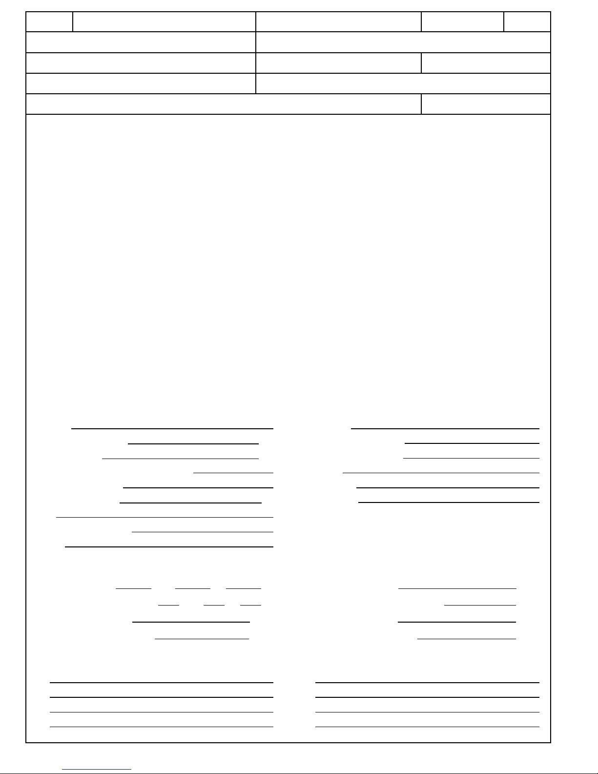
JOB NAME: LOCATION:
BUYER: BUYER P.O. # CARRIER #
UNIT NUMBER: MODEL NUMBER:
PERFORMANCE DATA CERTIFIED BY: DATE:
DESCRIPTION
Packaged air-cooled liquid chiller factory wired, piped, and charged with HFC-134a. Upward
discharge airflow minimizes directional sound and dissipates heat away from surrounding areas.
FEATURES
Cooler is mechanically cleanable ‘‘flooded’’ shell-and-tube type
with removable heads. It is tested and stamped in accordance
with ASME Code for a refrigerant working side pressure of
220 psig (1517 kPa) and a maximum fluid side pressure of
300 psig (2068 kPa) (250 psig [1724 kPa] in Canada) and is
insulated with
3
⁄4-in. (19 mm) closed-cell polyvinyl chloride foam.
Cooler can be equipped with electric heater to help protect against
cooler freeze-up (use of inhibited glycol anti-freeze recommended
for freeze protection).
Compressor is semi-hermetic twin screw design with refrigerant
gas cooled motor and integral oil filter and discharge gas muffler.
Complete thermal and electrical protection is provided.
Air-cooled condenser is constructed of fins mechanically bonded
to seamless copper tubes. Coils are leak and pressure tested at
450 psig (3103 kPa).
Condenser fans are direct driven 11-blade, shrouded axial type,
statically and dynamically balanced, discharging air vertically
upward, protected by coated steel wire safety guards.
Condenser fan motors are totally enclosed 3-phase with permanently lubricated bearings and Class F insulation (except speed
control motors).
Each refrigerant circuit includes oil separator, high side pressure
relief device, liquid and discharge line shutoff valve, filter drier,
moisture indicating sight glass, expansion/level control device.
Microprocessor control includes keypad with diagnostic display
displaying set points, time, system status (including temperatures,
pressures and % loading) and the alarm conditions.
Automatic compressor lead/lag.
Capacity control based on leaving chilled water temperature with
return water temperature sensing.
7-Day time scheduling of pump(s) and chiller.
60-Hz Models: 080, 090, 106, 115, 125, 136, 151, 161, 176, 206,
226, 251, and 265.
50-Hz Models: 080, 090, 105, 106, 115, 125, 136, 150, 160, 161,
175, 205, 225, 226, 250, and 265.
PERFORMANCE DATA
UNIT
Capacity
Compressor Input Power kW
Unit Input Power
kW
Minimum Outdoor Operating Temperature
Capacity Control Steps
Minimum Capacity % %
EER
Entering Air Temperature
Weight
COOLER
Cooler Fluid
Entering Fluid Temperature
Leaving Fluid Temperature
Flow Rate
Pressure Drop
Fouling Factor
ELECTRICAL DATA
Power Supply to Unit Volts Ph Hz
Power Supply to Control Circuit
Volts Ph Hz
Minimum Amps Circuit 1
Amps
Maximum Fuse Amps Circuit 1
Amps
Control Circuit Fuse Amps
Amps
Maximum Instantaneous Current Flow
Amps
Minimum Amps Circuit 2
Amps
Maximum Fuse Amps Circuit 2
Amps
OPTIONS
M
M
M
M
M
M
M
M
2
Page 3
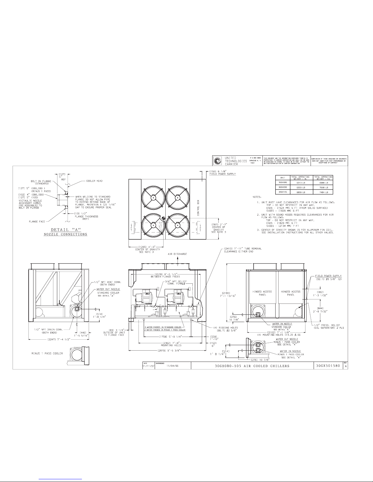
CERTIFIED DIMENSION PRINT
3
CUT ALONG DOTTED LINE CUT ALONG DOTTED LINE
----------------------------------------------------------------------------------------
Page 4
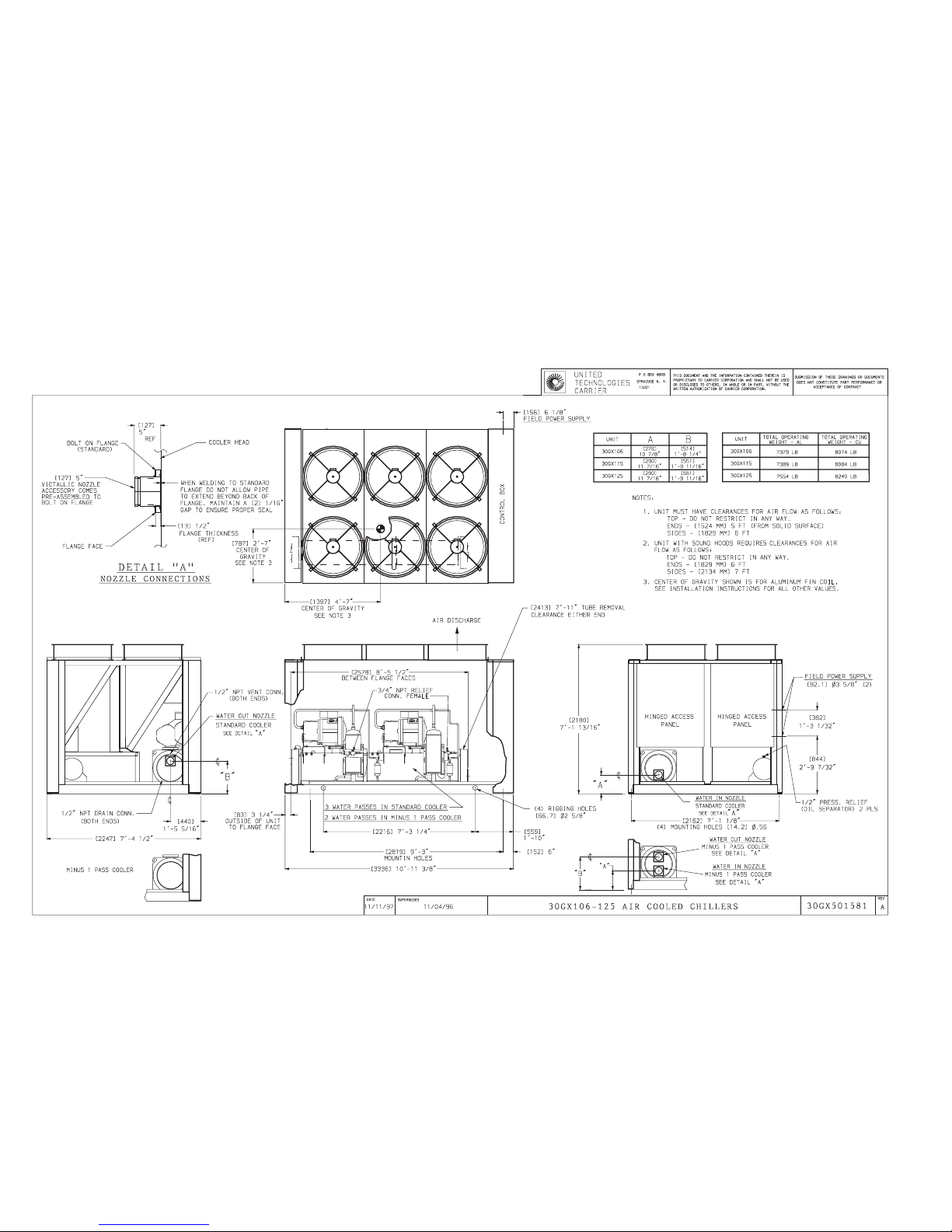
CERTIFIED DIMENSION PRINT
4
Page 5
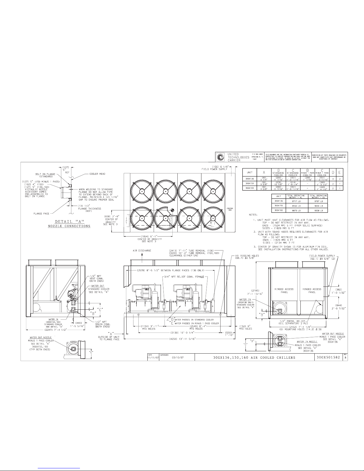
CERTIFIED DIMENSION PRINT
5
CUT ALONG DOTTED LINE CUT ALONG DOTTED LINE
----------------------------------------------------------------------------------------
Page 6
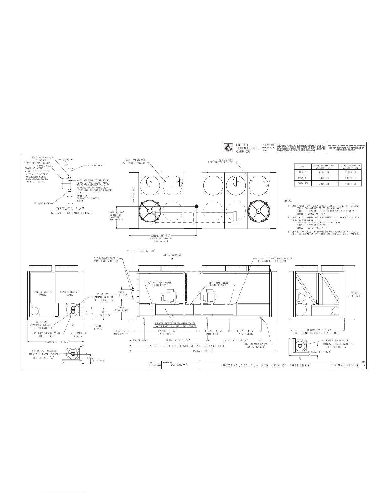
CERTIFIED DIMENSION PRINT
6
Page 7
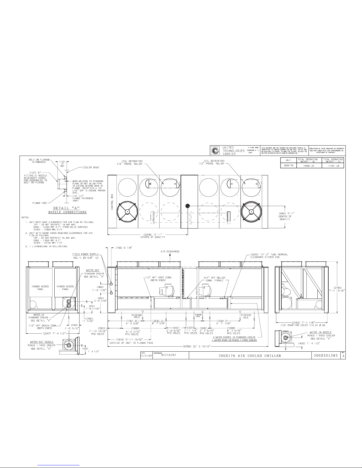
CERTIFIED DIMENSION PRINT
7
CUT ALONG DOTTED LINE CUT ALONG DOTTED LINE
----------------------------------------------------------------------------------------
Page 8
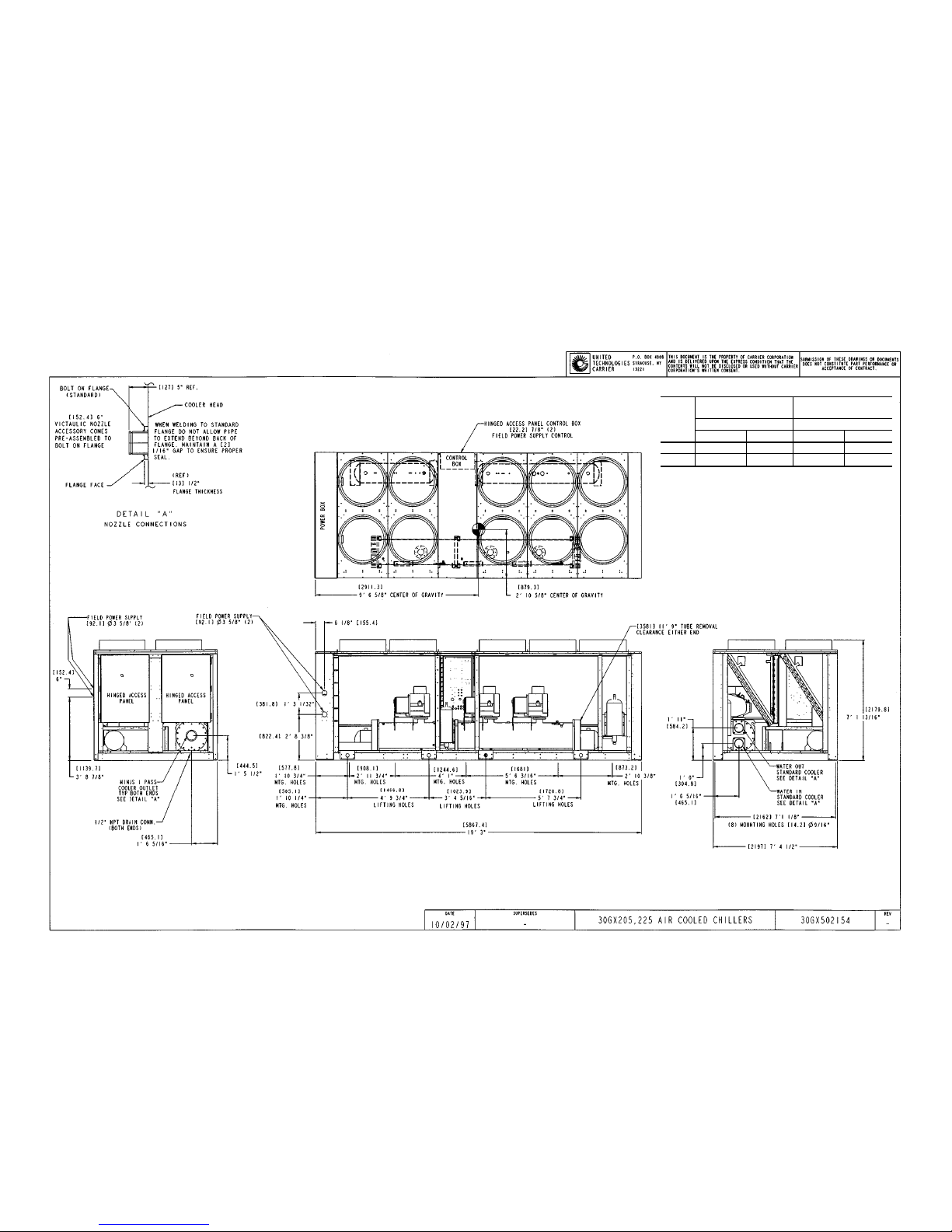
CERTIFIED DIMENSION PRINT
UNIT
30GX
TOTAL OPERATING
WEIGHT
TOTAL OPERATING
WEIGHT
Aluminum Fin Copper Fin
lb kg lb kg
205 12,184 5,538 13,569 6,168
225 12,364 5,620 13,749 6,250
NOTES:
1. Unit must have clearances for air flow as follows:
Top — Do not restrict in any way
Ends — (1524 mm) 5 ft (from solid surface)
Sides — (1829 mm) 6 ft
2. Unit with sound hoods requires clearances for air flow as
follows:
Top — Do not restrict in any way
Ends — (1829 mm) 6 ft
Sides — (2134 mm) 7 ft
3. Center of gravity shown is foraluminum fin coil. See installation instructions for all other values.
8
Page 9
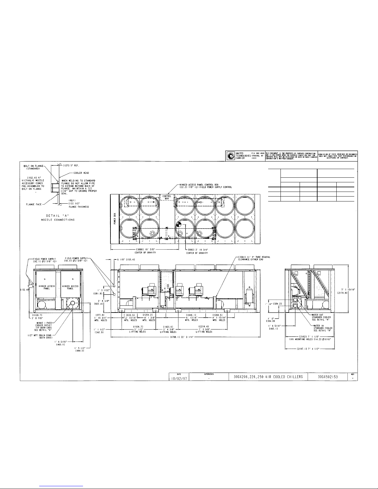
CERTIFIED DIMENSION PRINT
UNIT
30GX
TOTAL OPERATING
WEIGHT
TOTAL OPERATING
WEIGHT
Aluminum Fin Copper Fin
lb kg lb kg
206 12,794 5,815 14,462 6,574
226 12,974 5,897 14,642 6,655
250 13,194 5,997 14,862 6,755
NOTES:
1. Unit must have clearances for air flow as follows:
Top — Do not restrict in any way
Ends — (1524 mm) 5 ft (from solid surface)
Sides — (1829 mm) 6 ft
2. Unit with sound hoods requires clearances for air flow
as follows:
Top — Do not restrict in any way
Ends — (1829 mm) 6 ft
Sides — (2134 mm) 7 ft
3. Center of gravity shown is for aluminum fin coil. See installation instructions for all other values.
9
CUT ALONG DOTTED LINE CUTALONG DOTTED LINE
----------------------------------------------------------------------------------------
Page 10
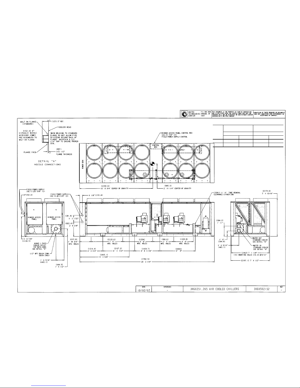
CERTIFIED DIMENSION PRINT
UNIT
30GX
TOTAL OPERATING
WEIGHT
TOTAL OPERATING
WEIGHT
Aluminum Fin Copper Fin
lb kg lb kg
251 13,774 6,621 15,549 7,068
265 13,829 6.286 15,604 7,093
NOTES:
1. Unit must have clearances for air flow as follows:
Top — Do not restrict in any way
Ends — (1524 mm) 5 ft (from solid surface)
Sides — (1829 mm) 6 ft
2. Unit with sound hoods requires clearances for air flow
as follows:
Top — Do not restrict in any way
Ends — (1829 mm) 6 ft
Sides — (2134 mm) 7 ft
3. Center of gravity shown is for aluminum fin coil. See
installation instructions for all other values.
10
Page 11
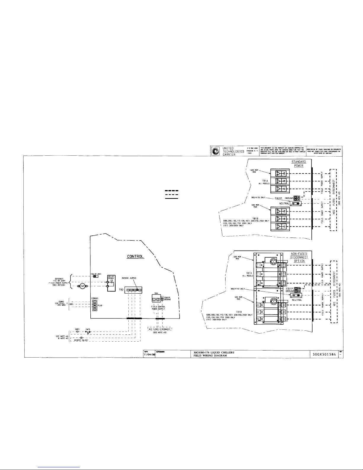
FIELD WIRING DIAGRAM
NOTES:
1. Factory wiring is in accordance with National Electrical Code (NEC). Field modifications or additions must be in compliance with all applicable codes.
2. Wiring for main field power supply must be rated 75° C minimum. Use copper for all
units. Maximum incoming wire size for each terminal block is 500 kcmil.
3. Power for control circuit should be supplied from a separate source through a field
supplied fused disconnect with 30 amp maximum protection for 115 volt control circuits
and 15 amp maximum protection for 230 volt control circuit. Connect control circuit
power to terminals 1 and 2 of TB4. Connect neutral side of supply to terminal 2 of TB4.
Control circuit conductors for all units must be coppr only. 380/415 control power wired
at factory. Requires field supplied neutral connection.
4. Terminals 13 and 14 of TB2 are for field external connection for remote ON-OFF.The
contacts must be rated for dry circuit application capable of handling a 24 vac to 50 mA
load.
5. Terminals 11 and 12 of TB2 are for chilled water flow switch (CWFS) and chilled water
pump interlock (CWPI) functions. The contacts must be rated for dry circuit application
capable of handling a 24 vac to 50 mA load.
6. Terminals T3 and T4 on relay board are for chilled water pump. The maximum load
allowed for the chilled water pump relay is 125 va sealed, 1250 va inrush at 115 or
230 volt.
LEGEND
CCN — Carrier Comfort Network
CWFS — Chilled Water Flow Switch
CWP — Chilled Water Pump
CWPI — Chilled Water Pump Interlock
EQUIP — Equipment
GND,GRD — Ground
TB — Terminal Block
Field Power Wiring
Field Control Wiring
Factory Installed Wiring
11
CUT ALONG DOTTED LINE CUTALONG DOTTED LINE
----------------------------------------------------------------------------------------
Page 12
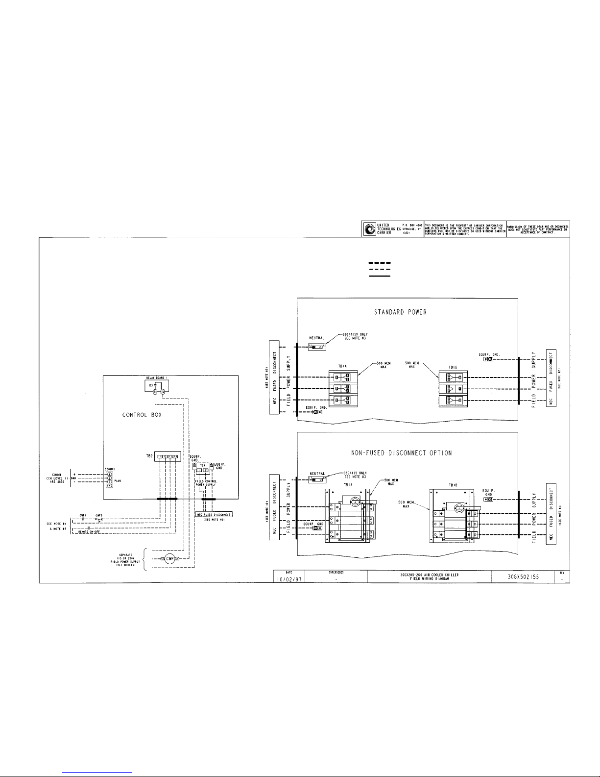
FIELD WIRING DIAGRAM
NOTES:
1. Factory wiring is in accordance with National Electrical Code (NEC). Field modifications or additions must be in compliance with all applicable codes.
2. Wiring for main field power supply must be rated 75° C minimum. Use copper for
all units. Maximum incoming wire size for each terminal block is 500 kcmil.
3. Power for control circuit should be supplied from a separate source through a field
supplied fused disconnect with 30 amp maximum protection for 115 volt control
circuits and 15 amp maximum protection for 230 volt control circuit. Connect control circuit power to terminals 1 and 2 of TB4. Connect neutral side of supply to
terminal 2 of TB4. Control circuit conductors for all units must be coppr only. 380/
415 control power wired at factory. Requires field supplied neutral connection.
4. Terminals 13 and 14 of TB2 are for field external connection for remote ON-OFF.
The contacts must be rated for dry circuit application capable of handling a 24 vac
to 50 mA load.
5. Terminals 11 and 12 of TB2 are for chilled water flow switch (CWFS) and chilled
water pump interlock (CWPI) functions. The contacts must be rated for dry circuit
application capable of handling a 24 vac to 50 mA load.
6. TerminalsT3 and T4 on relay board are for chilled water pump. The maximum load
allowed for the chilled water pump relay is 125 va sealed, 1250 va inrush at 115 or
230 volt. Minimum load required is 25 va sealed.
LEGEND
CCN — Carrier Comfort Network
CWFS — Chilled Water Flow Switch
CWP — Chilled Water Pump
CWPI — Chilled Water Pump Interlock
EQUIP — Equipment
GND — Ground
TB — Terminal Block
Field Power Wiring
Field Control Wiring
Factory Installed Wiring
12
 Loading...