

Page 1
L010125H40 - 0702
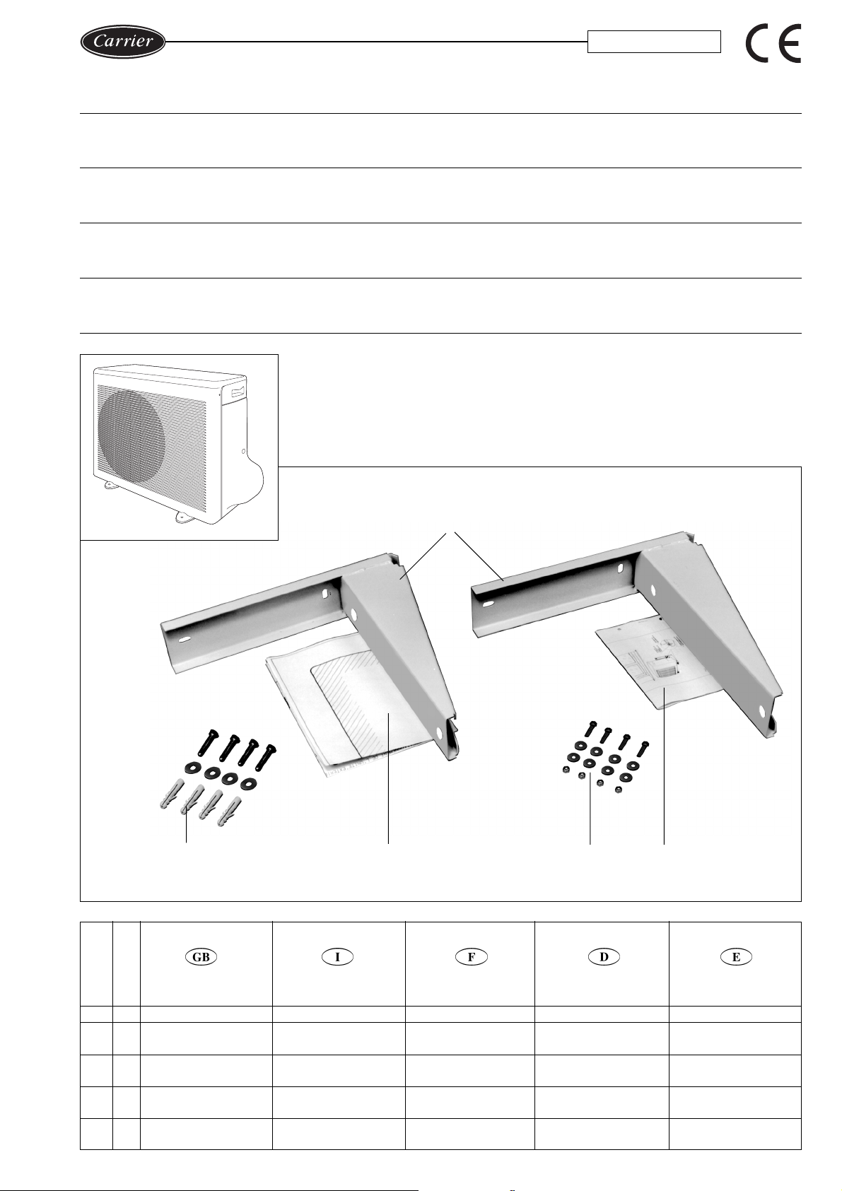
SPLIT SYSTEMS Outdoor unit wall bracket kit
AIR CONDITIONER installation instructions
CLIMA TIZZA T ORE
SISTEMA SPLIT
Istruzioni di installazione
kit supporto staffe unità esterna
CLIMA TISEUR À DEUX BLOCS Consignes d’installation
(SPLIT -SYSTEM) kit support de montage mural unité extérieure
SPLIT SYSTEM-
KLIMAGERÄT
Außengeräte-Wandhalterungs -Bausatz
Installationsanweisungen
ACONDICIONADOR Instrucciones de instalación
DE AIRE SPLIT conjunto de soporte para pared unidad exterior
38BC - 38BH
a
Ref. Q.ty
Rif. Q.tà
Ref. Q.té
Bez. Anz.
Ref. Can.
a 2 Brackets
b 4
c 1
d 4
e 1
DESCRIPTION
Screw anchors Ø10
screws and washers
Positioning
template
M6 screws, washers
and self-locking nuts
Installation
instruction
bcde
DESCRIZIONE
Staffe
Tasselli ad espansione
Ø10 con viti e rondelle
Dima di
posizionamento
Viti M6, rondelle e
dadi autobloccanti
Istruzioni di
installazione
DESCRIPTION
Consoles
Chevilles Ø10
vis et rondelles
Gabarit de
positionnement
Vis M6, rondelles et
écrous autobloquants
Consignes
d’installation
BESCHREIBUNG
Halterungen
Dübel Ø 10, Schrauben
und Unterlegscheiben
PositionierSchablone
M6-Schrauben,Unterlegscheiben
und selbstsichernde Muttern
Installationsanweisungen
Soportes
Anclajes roscados, tor-
nillos y arandelas Ø10
Plantilla de
colocación
Tornillos, arandelas y
tuercas autoblocantes M6
Instrucciones de
installación
DESCRIPCIóN
Page 2
1
Fig. 1 - Abb. 1
2
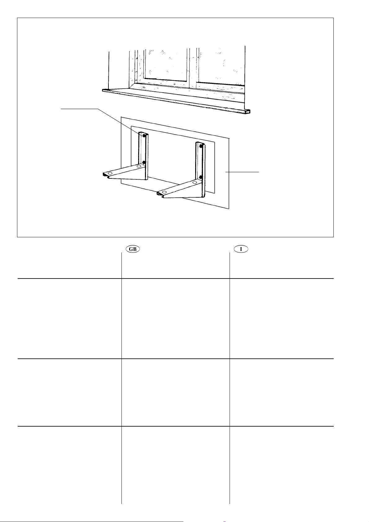
Building works
• Choose the unit installation position.
• Use the positioning template (ref. 3)
to make the fixing holes for the
brackets (ref. 1).
• Fasten the brackets to the wall with
the screw anchors (ref. 2) as
indicated in figure 1.
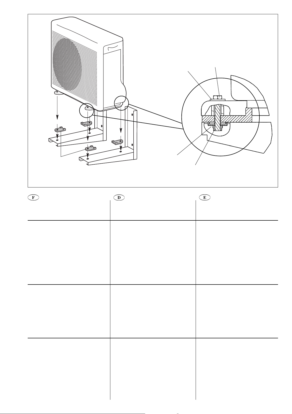
Unit installation
• Position the unit on brackets so that
the four unit feet fit are aligned with
the rubber pads on the brackets.
• Attach the unit to the brackets using
the four M6 screws, nuts and
washers (ref. 4) as shown in figure 2.
Fig. 1
1 Screw ancors,screws and washers
(rif. 2)
2 Positioning template (rif. 3)
Opere murarie
• Stabilire la posizione di installazione
dell'unità.
• Utilizzare l'apposita dima di
posizionamento (rif. 3) per eseguire i
fori di fissaggio delle staffe (rif. 1).
• Fissare a parete le staffe mediante i
tasselli e le viti (rif. 2) come indicato
in figura 1.
Installazione unità
• Montare l'unità sulle staffe
appoggiando i 4 piedini sui rispettivi
antivibranti.
• Fissare l'unità alle staffe con le 4 viti
più rondelle e dadi (rif. 4) come
mostrato in figura 2.
Fig. 1
1 Tasselli ad espansione, viti e
rondelle (rif. 2)
2 Dima di posizionamento (rif. 3)
Fig. 2
3 M6 screw (rif. 4)
4 Flat washer (rif. 4)
5 Flat washer (rif. 4)
6 Self-locking nut (rif. 4)
7 Rubber pads supplied with the unit
2
Fig. 2
3 Vite M6 (rif. 4)
4 Rondella piana (rif. 4)
5 Rondella piana (rif. 4)
6 Dado autobloccante (rif. 4)
7 Antivibranti forniti a corredo
dell’unità
Page 3
4
3
7
Fig. 2 - Abb. 2
T ravaux de construction
• Choisir la position d’installation de
l’unité.
• Utiliser le gabarit de positionnement
(réf. 3) pour faire les trous de fixation
pour les consoles (réf. 1).
• Fixer les consoles au mur à l’aide des
chevilles et des vis (réf. 2), comme
indiqué à la figure 1.
Installation de l’unité
• Positionner l’unité sur les consoles
de sorte que les quatre pieds de
l’unité soient dans l’alignement des
coussins de caoutchouc des
consoles.
• Fixer l’unité aux consoles à l’aide des
quatre vis M6, des écrous et des
rondelles (réf. 4), comme indiqué à la
figure 2.
5
Arbeiten am Gebäude
• Die Geräte-Installationsposition
wählen.
• Mit Hilfe der Positionier-Schablone
(Posten 3) die Befestigungslöcher für
die Halterungen (Posten 1) bohren.
• Die Halterungen mit den Dübeln
(Posten 2) wie in Abb. 1 gezeigt an
der Wand befestigen.
Geräte-Installation
• Das Gerät auf den Halterungen
positionieren, so dass die vier
Gerätefüße mit dem SchalldämmMaterial an den Halterungen
ausgerichtet sind.
• Das Gerät mit den vier M6Schrauben, Muttern und
Unterlegscheiben (Posten 4) wie in
Abb. 2 gezeigt an den Halterungen
befestigen.
6
T rabajos de construcción
• Elegir la posición de instalación de la
unidad.
• Utilizar la plantilla de colocación
(referencia 3) para hacer los agujeros
de fijación para los soportes (ref. 1).
• Fijar los soportes a la pared con los
anclajes roscados (referencia 2),
como se muestra en la figura 1.
Instalación de la unidad
• Colocar la unidad sobre los soportes
de manera que las cuatro patas de la
unidad queden alineadas con las
almohadillas de goma de los soportes.
• Fijar la unidad a los soportes
utilizando los cuatro tornillos, tuercas
y arandelas M6 (referencia 4), como
se muestra en la figura 2.
Fig. 1
1 Chevilles, vis et rondelles (réf. 2)
2 Gabarit de positionnement (réf. 3)
Fig. 2
3 Vis M6 (réf. 4)
4 Rondelle plate (réf. 4)
5 Rondelle plate (réf. 4)
6 Écrou autobloquant (réf. 4)
7 Coussins en caoutchouc fournis
avec l’unité
Abb. 1
1 Dübel, Schrauben und
Unterlegscheiben (Posten 2)
2 Positionier-Schablone (Posten 3)
Abb. 2
3 M6-Schraube (Posten 4)
4 Glatte Unterlegscheibe (Posten 4)
5 Glatte Unterlegscheibe (Posten 4)
6 Selbstsichernde Mutter (Posten 4)
7 Mit dem Gerät mitgeliefertes
Schalldämm-Material
3
Figura 1
1 Anclajes roscados, tornillos y
arandelas (ref. 2)
2 Plantilla de colocación (ref. 3)
Figura 2
3 Tornillo M6 (ref. 4)
4 Arandela plana (ref. 4)
5 Arandela plana (ref. 4)
6 Tuerca autoblocante (ref. 4)
7 Almohadillas de goma
suministradas con la unidad
Page 4

Carrier S.p.A. - Via R. Sanzio, 9 - 20058 Villasanta (MI) Italy - Tel. 039/3636.1
The manufacturer reserves the right to change any product specifications without notice.
La cura costante per il miglioramento del prodotto può comportare senza preavviso, cambiamenti o modifiche a quanto descritto.
La recherche permanente de perfectionnement du produit peut nécessiter des modifications ou changements, sans préavis.
Änderungen im Zuge der technischen Weiterentwicklung vorbehalten.
El fabricante se reserva el derecho de cambiar algunas especificaciones de los productos sin previo aviso. Printed in Italy
 Loading...