

Page 1
Carrier
Operating and Maintenance
Instructions
Automatic Water Strainer
29D
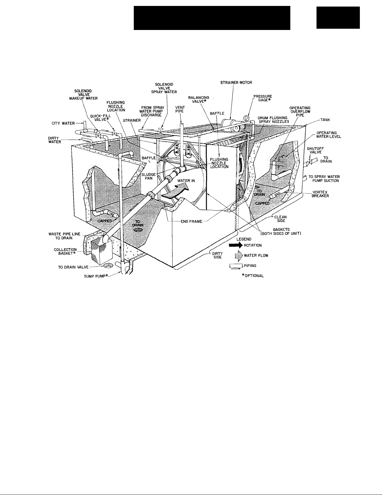
Fig. 1 - Typical Automatic Water Strainer Installation
UNIT DESCRIPTION
The 29D Automatic Water Strainer cleans
foreign matter from the return water of a
Rotaspray® system. Figure 1 shows a typical
installation.
OPERATING CYCLE
Water enters the open end of the strainer drum
and passes outward thru the perforated skin. For
eign matter is screened out of the water, and
covers the inside surface of the drum causing the
water level to rise on the dirty side of the tank.
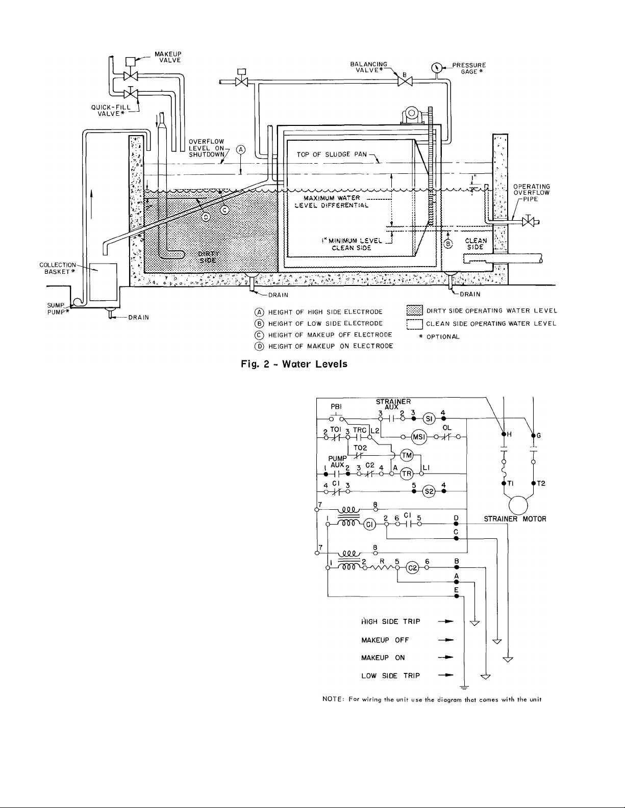
The water level on the clean side rises until it
reaches the height of the high side electrode A
(Fig. 2). This sets the strainer into operation.
The drum begins to rotate and the drum flushing
sprays are turned on. The dirty portion of the
drum passes under the sprays, and foreign matter
is flushed from the drum into the sludge pan. The
pan flushing sprays wash the foreign matter from
the pan into a drain or a perforated collection
basket. (The water drains from this perforated
basket into a sump, and can be returned to the
dirty side of the tank by a small auxiliary pump.)
After the drum is cleaned of foreign matter, the
water levels equalize, and the strainer stops after
the timed operating cycle.
When the water falls below the low side elec
trode B level (Fig. 2) the strainer starts to pro
tect the pump suction when:
1. The "Rotaspray" units evaporate water, caus
ing the water level on the clean side to drop
without a corresponding rise in water level on
the dirty side.
2. Changes in the system water flow requirements
suddenly drop the water level in the clean side
of the tank.
3. The high side electrode fails to operate.
I Carrier Corporation 1967 Printed in U.S.A.
12-67 29D-1SO
Page 2
f
CONTROL CIRCUIT
Automatic Operation - The water strainer con
trol circuit (Fig. 3) consists of a timer and
level controller. The control circuit is wired thru
an auxiliary contact on the recirculated or chilled
water pump starter. If the fused disconnect switch
is closed, the control circuit is activated when
the pump starts. The strainer is then controlled
automatically by the high or low side electrode.
When either electrode is energized, the control
circuit is completed. This starts the drive motor,
opens the spray water solenoid valve, and trips
the timer.
Normally, as the strainer begins to operate,
the water levels begin to equalize, de-energizing
the electrode. However, the timer contacts remain
closed for the preset timed cycle to maintain
strainer operation. The length of the timed cycle
can be adjusted to suit job requirements. At the
end of the timed cycle, the timer contacts open.
This normally stops the drive motor, and closes
the spray water solenoid valve. However, if the
tank water level is too low, the low side electrode
will maintain the makeup valve open for several
minutes, until the water level rises enough to de
energize the low side electrode.
Manual Operation - A momentary contact switch
is provided to bypass the automatic tank level con
troller and operate the water strainer for one
timed cycle. This switch permits operation of the
strainer when the water pump is shut down.
Cl
^2 - Relay Coi Is
MSI - Strainer Motor Starter
PB — Push Button
SI - Spray Wtr Solenoid Valve
Fig. 3 - Elementary Control Circuit
II0-I-60
S2 - Makeup Wtr Solenoid Valve
TM - Timer Motor
TR — Timer Relay Coil
o - Terminals on Components
0 — Terminals on Terminal Strip
Page 3

LUBRICATION
Main Shaft Bearing - Lubricate strainer main
shaft bearing with waterproof grease see Table 1.
This is a sleeve bearing and does not contain
a grease reservoir. Determine frequency of
lubrication from operating conditions. Lubricate
approximately every 500 hr or three months,
whichever is earlier.
Drive Chain - Lubricate drive chain with water
proof grease whenever main shaft bearings are
lubricated. See Table 1.
Table 1 - Drive Chain Grease Guide
HU MB L E O IL CO . Neb u la EP 2
TEX A C O IN C
MO BI L OI L CO . Mo bi lte x EP 2
No nv at ex N o 2
Gear Motor - Change oil after first week of oper
ating and 1000 hr or six months thereafter
whichever is earlier. See Table 2.
NOTE: Do not lubricate gear motor while
unit is in operation.
Table 2 - Gear Case Oil
AM BI EN T
AIR T EM P ( F)
25 - 6 0
50 - n o
SU V V IS C O SI TY
SEC 2 1 0(F )
70 - 1 00
125 - 15 0
SA E N O
90
140
OIL
Tex ac o M er op a 2
or E q ua l
Tex ac o M er op a 5
or E q ua l
Drum Rollers - Lubricate every 500 hr or three
months whichever is earlier (use Texaco Regal
AFB2 or equal).
Sludge Pan Bearing - This bearing does not re
quire lubrication.
CLEANING AND INSPECTION
Frequency of tank cleaning is determined by
operating conditions, which may require draining
and cleaning once each week. Clean all foreign
matter from strainer, tank, perforated collection
baskets and control electrodes. Each time tank is
drained and cleaned, check the following:
1. Drive chain and sprockets for wear, alignment,
and proper chain tension.
2. Rubber seal on entering side of drum for tight
ness. Make certain rubber is not damaged.
Page 4

For replacement items use Carrier specified parts
Manufacturer reserves the right to change any product specifications without notice.
Tab 13 29D-lSONew 12-67 Codes C and MF Catalog No. 532-904
 Loading...