

Page 1
Number One
AirCcndifoninq
Maker
------- ' T
1
Division of
^1^ Carrier Corporation
Carrier Parkway • Syracuse NY 13221
f
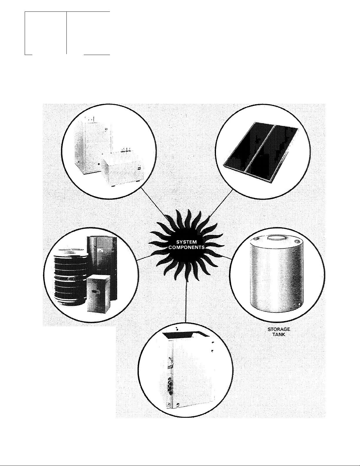
Solaround™Heat Pump System
PUMP
PACKAGES
SOLAR
COULgCTOS PANELS
WgATHERMASTER iS
<Wt* 2SQX Coil}
© Carrier Corporation 1978
HEAT PUMP
28QX
ENCASEO.COiL
Fig. 1 — Solaround System Components
Form 28QX-1SI
Page 2
Page
SAFETY CONSIDERATIONS............................................4
INSTALLATION
Step 1 — Check Equipment and Jobsite
..................................................................
..........................
4 — 6
4
• UNPACKAGE UNITS
• INSPECT EQUIPMENT
• REVIEW SYSTEM COMPONENT DATA
• COMPLETE SYSTEM REQUIREMENTS AND
CONSIDER SYSTEM RECOMMENDATIONS
Step 2 — Install Weathermaster III
Heat Pump System
..............................................................
6
• MAKE PIPING CONNECTIONS
• MAKE ELECTRICAL CONNECTIONS
Step 3 — Install and Insulate Water Storage Tank ... 7, 8
• TANK LOCATION
• REVIEW STORAGE TANK DESIGN
REQUIREMENTS
• INSULATE STORAGE TANK
Step 4 — Install Solar Collector Panels ........................ 8 — 12
• PLAN PHYSICAL POSITION OF PANELS
• PLAN THE COLLECTOR ARRANGEMENT
AND PIPING CIRCUITS
• CONSTRUCT COLLECTOR SUPPORTS
INDEX
• MOUNT THE COLLECTORS
• MAKE PIPING CONNECTIONS
• LEAK TEST THE COLLECTOR ARRAY
• INSTALL FLASHING, INSULATION AND
FRAME ENCLOSURE
Step 5a — Install Plain Water Pump Package . . .
• MOUNT ON FLOOR
• MAKE WATER PIPING CONNECTIONS
• LOCATE AND INSTALL THERMISTOR
SENSORS AND AQUASTAT BULBS
Step 5b — Install Glycol Pump Package
MOUNT ON FLOOR
MAKE WATER/GLYCOL PIPING
CONNECTIONS
• LOCATE AND INSTALL THERMISTOR
SENSORS AND AQUASTAT BULBS
Step 6 — Make Electrical Connections ....
• INSTALL BRANCH CIRCUIT FUSED
DISCONNECTS
• CONTROLPOWER
INITIAL START-UP
..........................................
MAINTENANCE AND SERVICE DATA . .
Page
12 - 16
16 - 19
20-22
23 -26
26-30
MODEL NO.
28QX036000
280X042000
REFRIG
CONTRJOL
Bypass
Accurater
NET WEIGHT
_Jlb]
95"”
i05
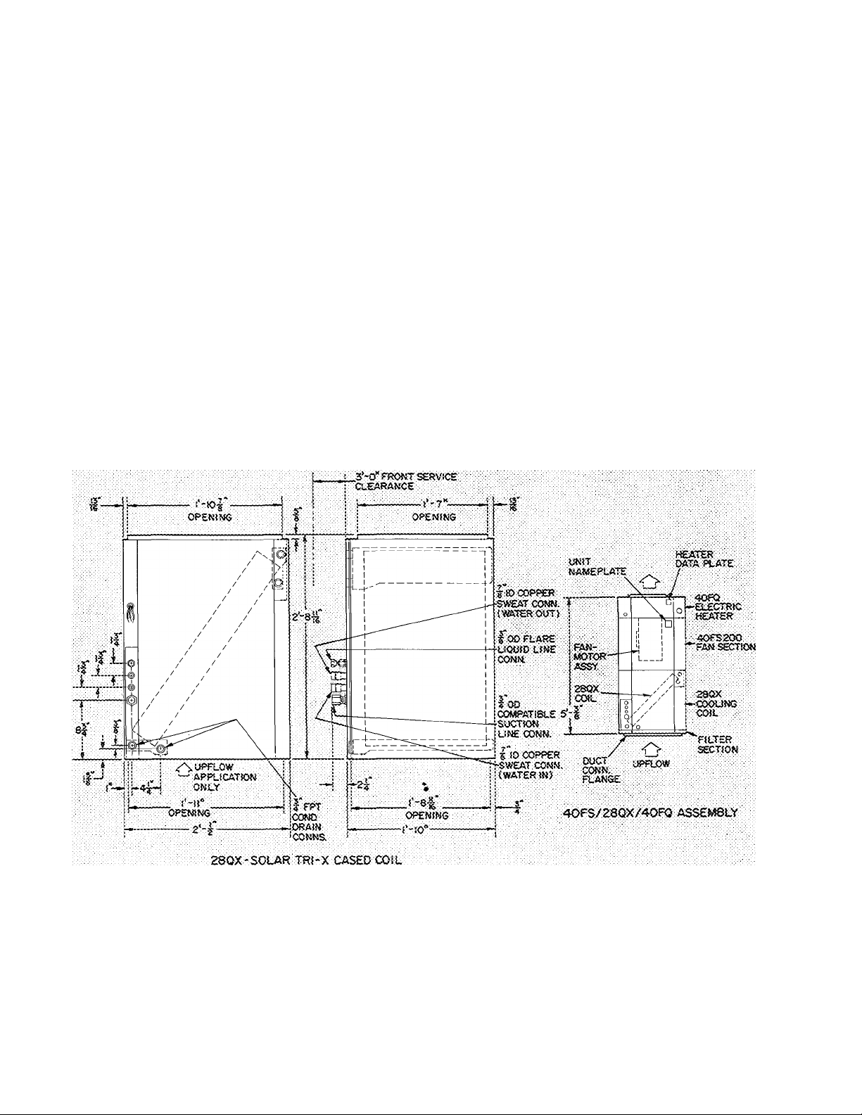
Fig. 2 — Dimensions and Connections
ACCESSORIES
F i Iter Rack
and Filters
Page 3
i FPT i.eAV»M6 l-iQUIO CONN.-
COPPER ABSORBER PLATE —.
SELECTt'.'E SypTACe
♦ FPT £NTER^^K5 WATER 'IXJNNECTiON
PUMP
UM(T
MO.
34GL167
'34gUs7
34GL367
34WA1S7
EXT??ti&£D
ALUMJRUM
ROUSINO
■NSULATiON
yjSE-!N-STR(P ■w£;G.-T7
SOU«i COtueCTOR panel
SiWGl£ GLAZED i !6 L8S
OOUSLE GLAZEO 14S LBS
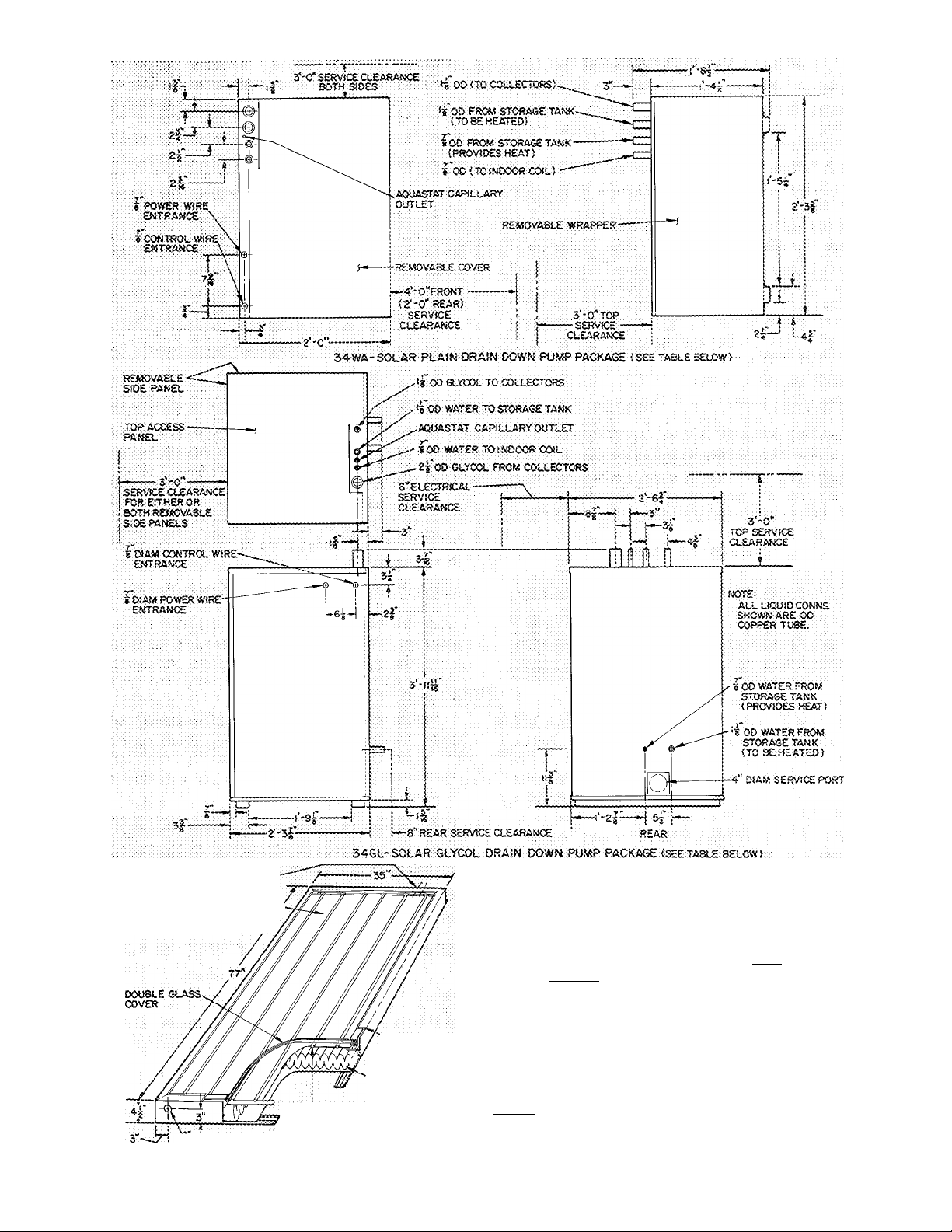
Fig. 2 — Dimensions and Connections (Cont'd)
34WA257
34ifA367
NOTES;
1, Oimc-nsjiX!s ar.c connecticrw (or :3iiHO/40 r-S outnp
sections are siiow:t in tne instaiiation booklets for those
cnits.
2. Ditriensionai data for field suppiied storage tank varies,
with type and capacity of tank supplied. See Storaije'
. Tank lastaliatiod. Step s.
3
ELEC ; CAPACiTY iNETVfT'i
¡collector;
CHAR. *7 PT W.C.
(Gpin;
2;":
t:.5-;-60P-
! ACCESSORIES
(lb)
2.32
:.;is
C’'cr::c''vi 'C sN-cior
T her.'ri;>:;io-
150
Page 4

SAFETY CONSIDERATIONS
Installation, start-up and servicing of this equip
ment can be hazardous due to system pressures,
electrical components and location of equipment
(roofs, elevated structures, etc.).
Only trained, qualified installers and service
mechanics should install, start-up and service this
equipment.
Untrained personnel can perform basic main
tenance functions of cleaning coils, filters and
replacing filters. All other operations should be
performed by trained service personnel.
When working on the equipment, observe pre
cautions in the literature, tags, stickers and labels
attached to the equipment and to any other safety
precautions that apply.
• Follow all safety codes.
• Wear safety glasses and work gloves.
• Use caution when handling or working on glass
covered equipment such as solar collectors.
• Use care in handling, rigging and setting bulky
equipment such as storage tanks and solar
collectors. Be sure power to equipment is shut
off before performing maintenance or service.
INSTALLATION
IMPORTAMT; Follow unit location,, height
proxiimty and piping requirements in this
booklet carefully to enhance system efficiency,
and to avoid system failure. Read entire book
let before starting installation.
Step 1 — Check Equipment and Jobsite
UNPACKAGE UNITS — Move units to final
location. Slide units from cartons, taking special
care not to damage service valves, pipe connec
tions, compatible fittings or grilles. Rig solar
collector panels prior to unpackaging to prevent
possible damage, see pg 8.
INSPECT EQUIPMENT — File claim with shipping
company if shipment is damaged or incomplete.
REVIEW SYSTEM COMPONENT DATA - Units
comprising a Solaround''"''^ System are shown in
Fig. 1 and Table 1. Dimensional data in Fig. 2. As
shown, the Solaround includes a standard
38HQ/40FS heat pump system with addition of
equipment to provide solar assistance during heat
ing season. The pump package, solar collector
panels, water storage tank and a section of 28QX
(Tri-X) indoor coil are a water heat transfer circuit.
Heated water, provided by solar panels, is pumped
from storage tank to indoor coil for water-toindoor-air heat transfer.
Accessory Hot Water Preheater reduces energy
required for heating domestic hot water during
cooling and heating seasons.
All Solaround system units are preselected with
the exception of field-supplied water storage tank.
Purchase or fabricate tank according to factory
specifications. See Step 3, pg 7, and 28QX
Application Data booklet.
Tri-X (28QX) Indoor Coil has separate water and
refrigerant circuits essential to the Solaround
system. The Tri-X serves 3 functions: transfers heat
pump (refrigerant) heating or cooling to indoor air;
transfers heat from storage water to indoor air;
transfers heat pump heat and heat from storage
water to indoor air.
The Tri-X is assembled to 40FS fan section and
40FQ electric heater in same manner as other 28
Series coils.
Plain Water or Glycol/Water Pump Package and
Solar Panels -- Water or glycol/water mixture is
pumped thru solar collector panels by pump
package. The liquid absorbs solar heat as it flows
thru the panels and is returned to storage tank
(plain water system) or expansion tank (glycol
system).
Both plain water or glycol systems, when
properly installed, feature fail-safe draining down
of liquid from solar panels to storage tank (when
circulating pump goes off). This prevents freeze-up
damage to panels.
CAUTION: A glycol system }.>5 preferable in
areas where prolonged periods of sab freezing
temperatures occur. Correct solar panel piping,
including a 2-1 /8 in. liquid draindown Kne, is
essential for proper system operation.
Table 1 — Solaround Systems*
PUMP PACKAGES
Water
34WaT67
34WA257
34WA367
*Any size water or glycol pump package and pre-determined number
of solar panels can be used with one of the Weathermaster III heat
pump assemblies above, i e 34WA257, 10 solar panels, 38HQ140,
38HQ960,40FS200/28QX042/40FQ920 - (15 kw) See Solaround
system Application Data booklet for Selection Procedure
Glycol
"31GÌLÌ67 '
34GL257
34 GL 367
SOLAR COLLECTOR PANELS
Min No.
Max No.
30
WEATHERMASTER III HEAT PUMPS
Indoor
Compr
Section
38HQ
J34
. - ^
NOTE:
On 40FQ-25 and 30 kw electric heaters, remove 60-va control trans
former and replace with 75-va transformer (part no HT01 BD235)
available from Carrier Service Parts Center
Outdoor
Coil
Section
38HQ
-
~940
^ 200
-200
^^960
2ÓÒ
Indoor Unit Assembly
Fan
4£FS
Coil
28QX
036^
036
042
Electric Heater
40FQ920-
10 to 30 kw
Page 5
All water supply lines leaving storage must be more than 6 in from bottom of tank but no closer than
2 ft from lowest water level
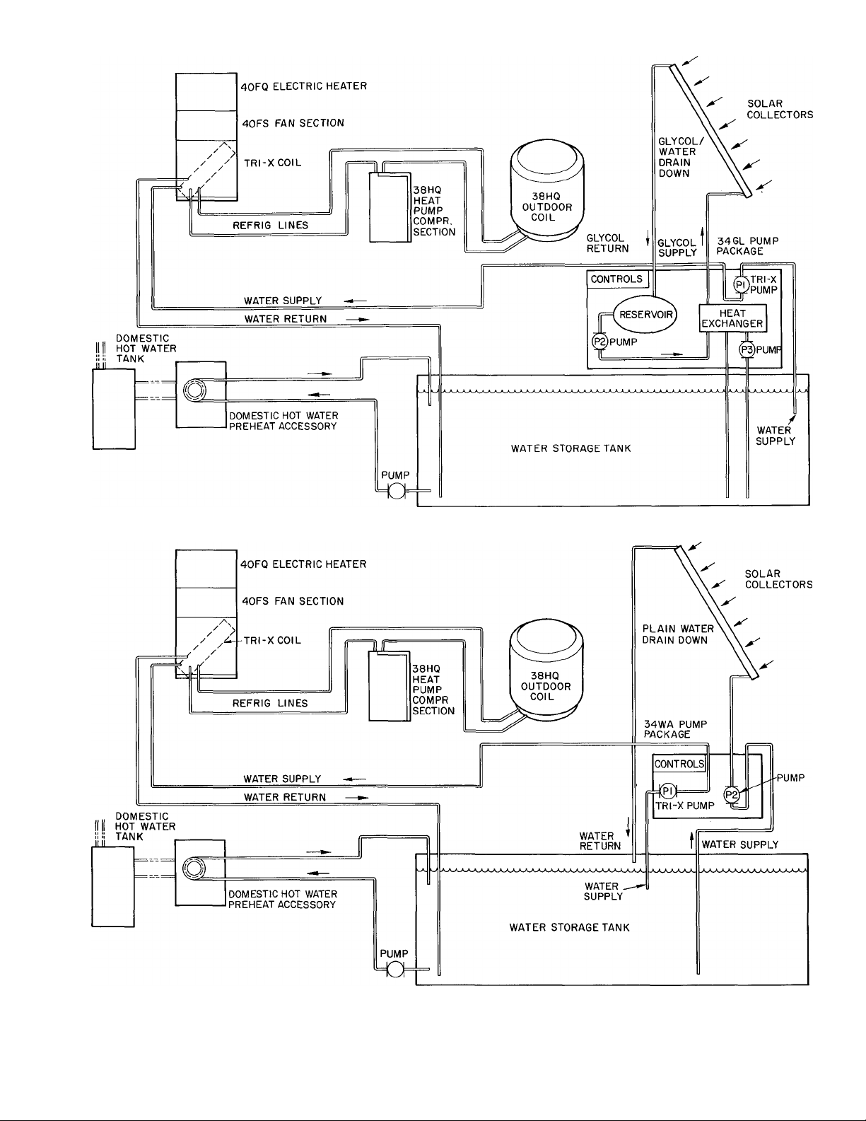
Fig. 3 — Typical Water or Glycol — Solaround System Schematic
Page 6

The plain water Solaround'''''^ System has 2
water piping loops — a solar collector panel loop
and a Tri-X coil loop. The glycol system has 3
piping loops — a collector panel water/glycol loop,
a water/glycol to water heat exchanger loop (thru
the pump package), and a Tri-X coil water loop.
See Typical Piping Schematic diagram. Fig. 3. Solar
panel placement on roof must be at correct angle
to absorb maximum amount of solar heat.
Solaround System Selection for each installation is
provided by Carrier Solar CLIC (Computer Load
Information Center). It computes number of solar
collector panels required, angle placement of
panels, volume of water storage tank, supply piping
sizes, and most beneficial accessory hot water
preheating arrangement. Capacity ratings and
system selection data are contained in Solaround
System Application Data.
COMPLETE SYSTEM REQUIREMENTS AND
CONSIDER SYSTEM RECOMMENDATIONS ^
Plan to locate system components as close together
as possible for easier installation, service and higher
system operating efficiency. Use piping schematics.
Fig. 16, 17, 23 and 24, as a guide. Before starting
installation, study remaining system requirements
and installation data, page 4 thru 22. Adjust
component location as required.
WARNING; An improper installation can cause
system to .maifunction and damage could result.
Summary of System Installation Requirements
necessary for proper operation of plain water or
glycol systems:
a. Pitch solar panel piping downward in vertical
plane a minimum of 1/4-in./ft for proper
drainage to storage tank.
b. Vent storage tank with 1/4-in. tubing.
c. Be sure all water pumps have a positive suction
head (minimum liquid pressure at pump inlet)
by locating pumps a minimum of 2 ft below the
lowest water level in storage tank.
d. Install a storage tank drain.
e. Provide a closed loop piping system for Tri-X
coil by terminating inlet and outlet line a
minimum of 6-in. from bottom of storage tank.
f. Horizontal runs of water supply lines leaving
the storage tank must not be above the lowest
water level in storage tank unless a closed loop
system (item e) is used. This prevents lines from
draining and loss of pump prime.
g. Install pump packages indoors and where tem
perature does not fall below freezing.
System Recommendations
a. Locate all indoor equipment, particularly the
storage tank, pump and control package and
fan coil at the same height level and in close
proximity, to each other for easier piping.
It is recommended that the Tri-X coil be at the
highest point in the coil water piping loop but
not more than 6 ft above water level in storage
tank. This ensures easier air venting and elim
inates special water filling procedure, pg 23.
b. Avoid additional installation, service and main
tenance problems by not burying the storage
tank. See pg 7.
c. Do not use any additional valves in piping other
than those that are specified by the installation
instructions.
d. Locate solar collectors directly above pump
package at a height not exceeding 30 ft from
top of water in storage tank to top of collector.
e. Actual length of piping from storage tank to
the pump package must not exceed 15 ft or
remote aquastat installation is required.
Step 2 — Install Weathermaster III Heat Pump
System
CAUTION: Observe all precautions included in
3SHQ and 40FS installation Instruciions.
Follow normal installation procedure for 38HQ
compression section, outdoor coil unit and 40FS
indoor fan coil assembly. (See wiring changes on
pg 20.) Refer to 38HQ and 40FS Installation
Instructions supplied with units. Available acces
sories for the heat pump system can be used
without deviation from an application where the
heat pump alone is installed.
Assemble the Tri-X coil (casing) with 40FS fan
section and 40FQ electric heater in same manner as
other 28 Series coil for upflow airflow. Horizontal
airflow assemblies are permissible, but require a
field fabricated horizontal condensate collector.
Unit cannot be installed in downflow position. Coil
inlet duct connection flanges are provided on 40FS
filter section rack. It is recommended that as
sembled fan coil be located in same area as other
interior system components, with the Tri-X at
highest point in water piping loop but not more
than 6 ft above water level in storage tank, pg 13.
The fan coil can be located elsewhere with restric
tions placed only by the allowable length of
interconnecting refrigerant tubing.
MAKE PIPING CONNECTIONS - Tri-X coil has
Compatible Fitting refrigerant line connections and
copper pipe stubs for water line sweat connection.
Replace the AccuRater'^^ refrigerant control
piston in the Tri-X coil as required before connec
ting refrigerant lines. See Table 2 for piston sizes.
Make refrigerant line connections. Use a back-up
wrench on AccuRater when making refrigerant
liquid line connections. Follow recommended
piping length in 38HQ booklet.
Water line connections are described under Step
5a and 5b.
MAKE ELECTRICAL CONNECTIONS
See
Step 6 on pg 20 for wiring connections.
Page 7
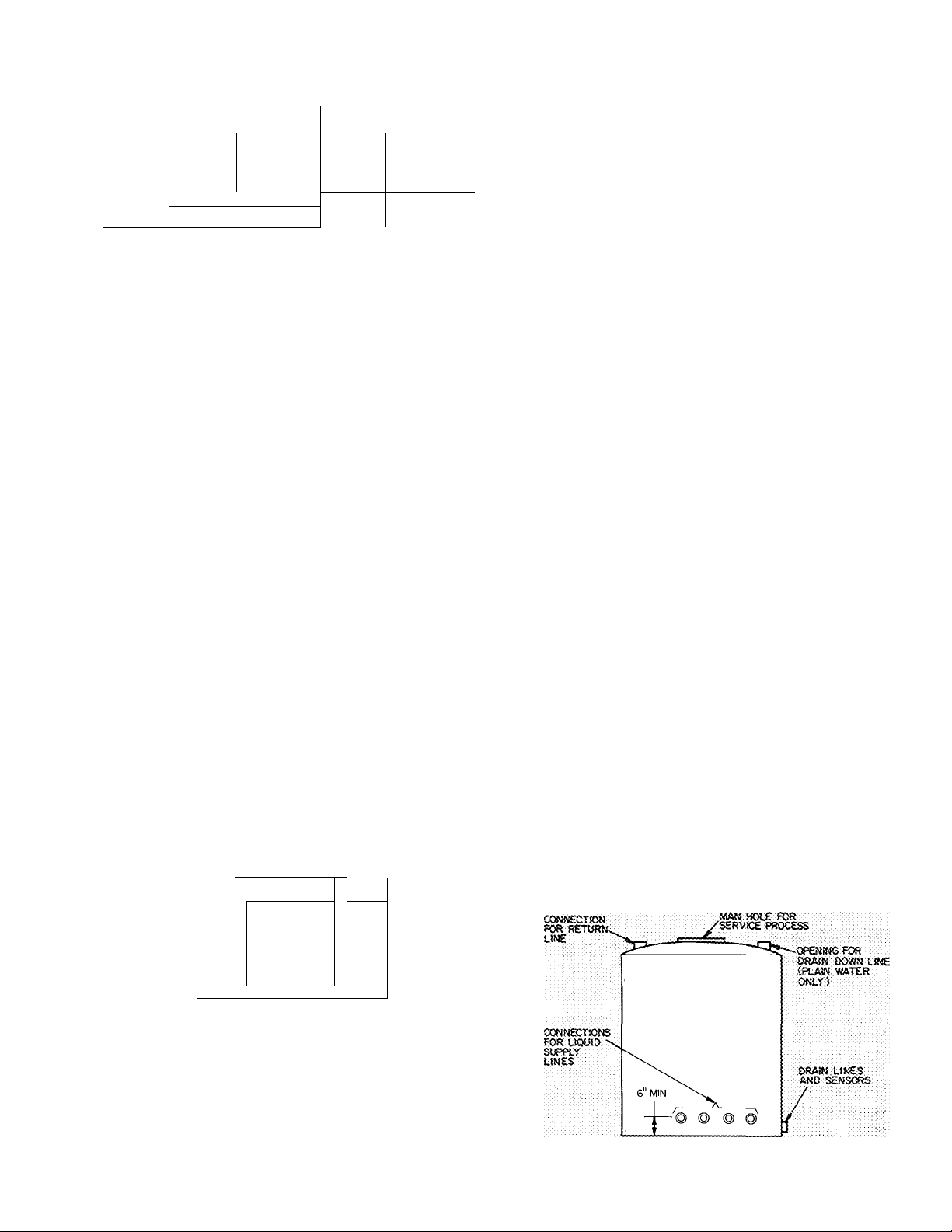
Table 2 — Accu Rater Refrigerant Control
Piston Data
OUTDOOR
INDOOR
COMPR
SECTION
38HQÌ27
38HQ134
38HQ140
'■'Standard factory-installed AccuRater piston. Remaining
" pistons are field installed
Step 3 — Install and Insulate Water Storage Tank
COIL SECTION
Required
Model
38HQ945 3
38HQ940
38HQ960 s
AccuRater Model
Piston (no.)
4
INDOOR COIL
Required
AccuRater
Piston (no.)
28QX036 5
28QXÓ36 6
28QX042
3
CAUTION: A large storage tank full of water
weighs several ions (l-gal. of water weighs 8.3
jbs). Structure must be able to support wei^it
of full tank. Use care wlren rigging, handling
and setting tank in place. Buried tanks are not
recomraended.
Capacity of tank (gal.) is specified by Carrier
Solar CLIC program. See Application Data for
storage tank design parameters. Review essential
tank design requirements.
Use correct type of tank for building configura
tion and construction status: Full or partial
basement, crawl space or slab-on-grade; new con
struction versus existing building (retrofit). Loca
tion of storage tank inside existing building generally
requires vessels which can be assembled on site.
TANK LOCATION — Use an indoor, above ground
tank whenever possible. Do not install tank where
temperature falls below freezing. Consider total tank
weight full of water (a full 1000 gal. steel tank
weighs over 4 tons), possible condensation and water
leak problems, and Solaround’''''^ System compo
nent location and piping requirements (pg 6).
Above or below ground tanks require a top man
hole (access) cover and service/maintenance area
adjacent to piping, aquastat and thermistor sensor
location (see pg 14). When excavating for below
ground tank, provide service clearance as indicated.
,— SERVICE AREA—,
REVIEW STORAGE TANK DESIGN
REQUIREMENTS
1. Size — The tank should be sized to hold
approximately 1.5—2.5 gal./ft2 of solar
collector area; 750 to 2000 gallons.
2. Temperature — The tank must be able to
withstand an operating temperature range of
80 F to 200 F without degradation.
3. Durability — The tank must provide a mini
mum life of 20 years.
4. Construction — The tank must be leak resist
ant. It will be necessary to treat some tanks
(concrete, wood) to ensure leak resistance.
They must also resist corrosion and chemical
or moisture deterioration. They must be able
to withstand the hydraulic pressures exerted
by their contents.
5. Shape — The shape will be optimum when the
surface to volume ratio is a minimum (to
reduce insulation requirements). It is best to
use a tank that will require a minimum of
structural and support framing.
6. Serviceability — The tank must have an access
hole to provide for servicing and maintenance.
It must have openings available for placement
of sensors (pg 14) and for inlet and outlet
piping. The outlet piping must be: minimum
6-in. from bottom of the tank to preclude
fouling or sediment; at least 2-ft from top of
the tank so that the water pumps will have
their required suction head (supplied by the
tank’s hydraulic pressure). See Fig. 13. There
must be provision at the top of the tank for an
atmospheric vent.
7. Heat Retention — The tank must provide a
high degree of heat retention. Insulate entire
tank (including bottom) to an insulation value
of R-20. Insulation must be kept dry.
8. Codes — The tank must be in conformance
with local codes. A recommended guide is
HUD Intermediate Minimum Property
Standards.
9. Make drain provision.
10. Clean tank prior to use.
, c=:
-cz
■ - ^
■'I
, -
Disadvantages of below ground tank include:
difficult to install, insulate and maintain; limited
service access to piping and controls; higher risk of
freezing; tank leaks may be nondetectable; a leak
into tank can cause water fouling and system
damage. A rise in ground water level and a partially
filled tank can result in tank floatation and
possible damage or hazard. Insulation of buried
tanks can also be adversely affected by soil
conditions and moisture.
Fig. 4 — Typical Steel Tank
Page 8
INSULATE STORAGE TANK - Prior to making
the tank installation, consider that the tank will
have to be insulated. The insulation will have to be
placed all around the tank, including underneath it.
This can be accomplished by either placing an
insulating pad beneath the tank (one which can
carry the weight without degrading) or by mount
ing the tank on channels. The channels should be
high enough to accommodate the necessary thick
ness of insulating material. Tank should not be
completely insulated until it is leak tested. See
Initial Start-Up on pg 23. The recommended
insulation level for indoor tank locations is R-20.
Acceptable insulation materials depend upon the
tank type and location. Use only non-toxic
insulating material. Typical insulation and thick
nesses for R-20 are:
Extruded Styrofoam (not bead board)
with skin
Urethane
........................................................
4-1/2 in.
................................................................
4 in.
Fiberglass, Batt......................................................6 in.
Fiberglass, High density board
.............................
5 in.
Indoor Locations
a. Insulation must meet HUD flame spread limits
as follows (ASTM E84-70):
Plastic Foam 25
Other 150
b. For moisture permeable tanks such as concrete
or wood, the insulation should be designed to
avoid trapping moisture. Low permeability
closed cell foam insulation should be used. If
fiberglass is used, a moisture barrier should be
provided at the tank surface; and if a cover is
used over the fiberglass, it must be permeable
(such as canvas).
c. Tank lids or manholes must have a positive seal
to prevent moisture loss into the insulation or
the occupied space. Lid or indoor cover must
have positive lock in open position so that
servicing can be done safely. Do not enter tanks
without person(s) capable of pulling you out of
tank in attendance.
Outside Locations (not recommended)
a. Recommend foam in place of urethane insula
tion, or closed cell foam insulation boards such
as urethane and styrofoam.
b. Recommend a plastic film (10 mil poly
ethylene) liner for the excavation, into which
the preinsulated tank is placed, or into which
the insulation is foamed around the tank. Do
not cover controls or piping with foam. Sealing
of joints in slab type insulation should be made
with mastics or adhesives recommended for the
type of insulation used. Consider tank freeze-up
protection.
Step 4 — Install Solar Collector Panels
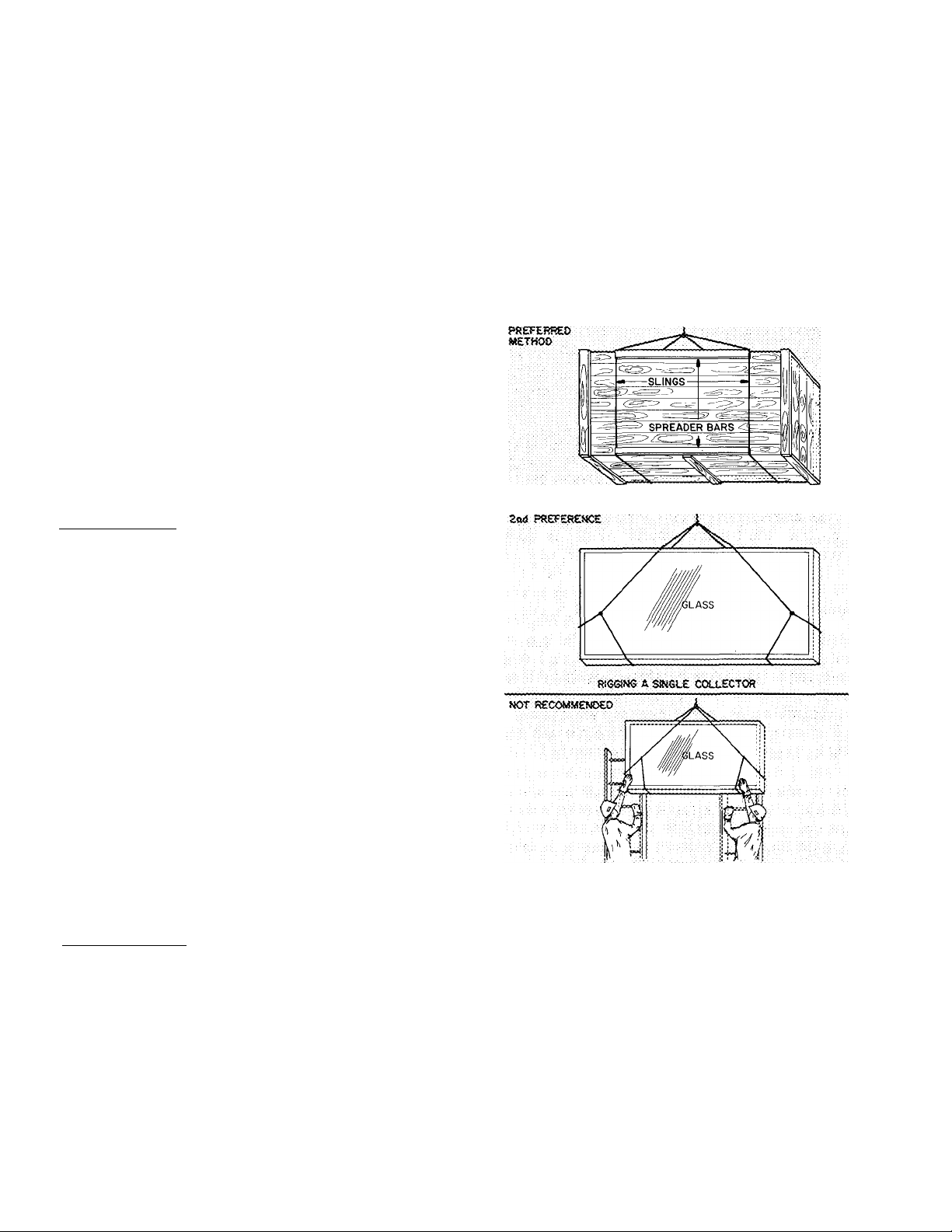
CAUTION: Be careful rigging, handling and
installing solar coiiectoxs. Tops of coHectors are
^ass and ЪгеакаЫе.
Rig and lift collecior(s) to roof before un
packaging from shipping crate or carton. Lift
with boom tnick or crane. If Iiand-Iifted to
roof, slide single collector up 2 ladders vrith a
guide rope on top and 2 men on roof pulling on
rope and taking weight off 2 men below. Use
extreme caution not to lose balance or control
of rope.
RIGSiNG A CRATS OF COLUSCTORS
ROiSTiNG A SlNGtX COLLECTOR UP TWO LADDERS
Do not use solar collector as a primary' roof
surface. Mount them on a roof constructed to
good roofing standards.
Properly seal all entries thru roof including
where collector sleeper frame or mounting
frante is attached to roof.
Flash sieeper frame or mounting franre to
prevent entry' of moisture and ice or snow
build-up beneath collectors installed in areas
where subfreezihg temperatures occur.
Number of panels required, mounting angle
(slope) of panels and liquid supply pipe size (OD)
is specified by Carrier solar CLIC program and
included in job plans. Refer to Fig. 2 for panel
Page 9
PRESSURE R£U£F mVE
ÎSI.VCOL SlfS^MS OWW '
EfOD.
RETliRN
UNE
SETORfi
i:
!•. ■
'i
~~ir
supply
„2^00
RETUSti
LSŒ
R£T«i»t
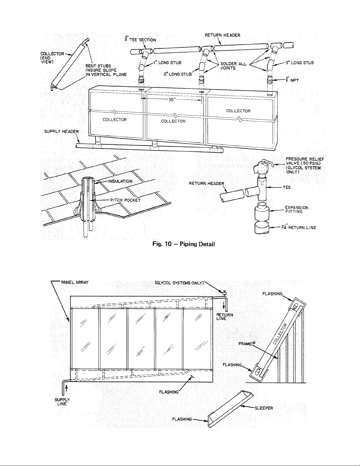
headers a minimum of 114-in.lft in vertical plane
for acceptable panel drainage. A slope of 3/8-in./ft
or 1/2-in./ft assures better panel drainage.
CAUTION: For proper system operation,
install eoilectors in recommended pattern arid
slope horizontal Ijeaders as specified, incorrect
instaliation can result in extensive system and
building damage.
Colleciors are made of ^ass. Use care in rigging
and handling. Do not use panels as primary roof
surface.
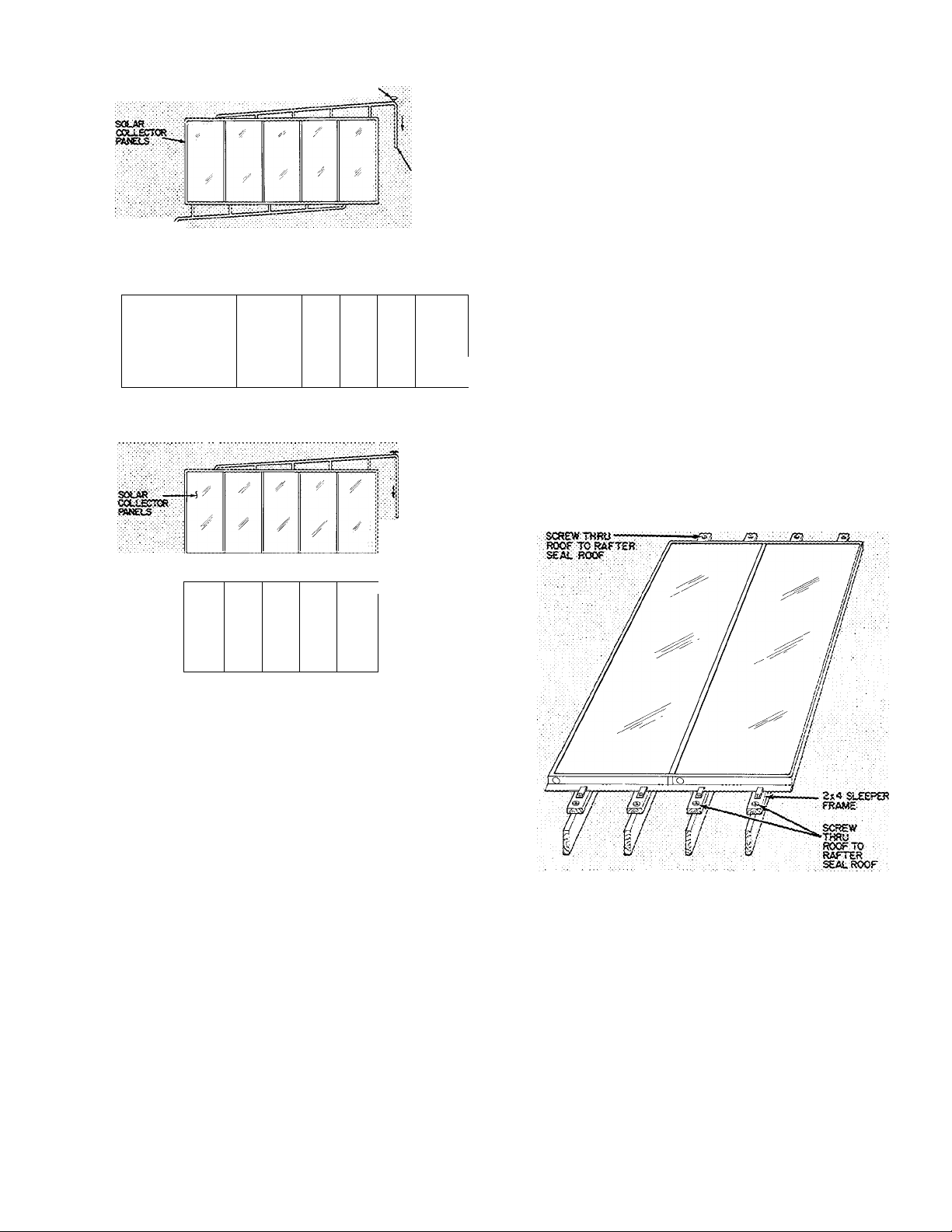
CONSTRUCT COLLECTOR SUPPORTS - Con
struct a framework to support the collectors based
on panel arrangement and circuiting pattern.
1
If the slope of the roof is the same as that
required for the collectors, construct a wooden
“sleeper frame.” Use 2-in. x 4-in. boards that lay
directly on the roof. Fig. 6. Construct frame so it
can be flashed and sealed. This prevents moisture
from accumulating behind the collector. Treat
sleepers with wood preservative and paint.
/
'
'
/
NCfTE;
^KR■ RECWitttENOEO DUE TO OECREASED EPFICSR«
HOWEVER ROOP /WEA L«frAT50NS MAY liECESStTSTE
TUB ARRANSEMcRT.
Fig. 5 — Collector Arrangements
'/
/
/
dimensions. Complete the following steps to install
panels:
PLAN PHYSICAL POSITION OF PANELS - For
maximum heating capacity, face the collector
panels due south ± 5 degrees. The angle or slope of
the collectors above the horizontal plan is normally
the latitude of the installation 15 degrees. Any
deviation from specified mounting position can
result in reduced heating performance. Be sure not
to place collector panels in areas shaded by trees or
buildings during portions of the day when sig
nificant amounts of solar energy can be obtained.
PLAN THE COLLECTOR ARRANGEMENT AND
PIPING CIRCUITS - There are 2 collector mount
ing arrangements recommended for installation in a
specific space, and for correct piping circuits. See
Fig. 5. Butt collectors next to each other to
minimize heat losses. Slope horizontal piping
NOTES:
1 Treat framing with preservative
2 Flash framing to prevent entry of moisture in subfreezing cli
mates (See Fig 11 )
Fig. 6 — Typical Collector "Sleeper" Framing
If an upright mounting frame is required, use
2-in. X 4-in., 2-in. X 6-in. (or heavier) boards or
aluminum framing material. Construct and install
frame perfectly level to the horizontal plane.
Locate bottom frame members directly over roof
rafter. Anchor the frame to roof rafters with
screws. Seal anchor points thoroughly to prevent
water leakage. A typical mounting frame is shown
in Fig. 7. There should be no horizontal surfaces
within 3 ft of the framebase, so that drifting snow
cannot accumulate on collectors.
Page 10
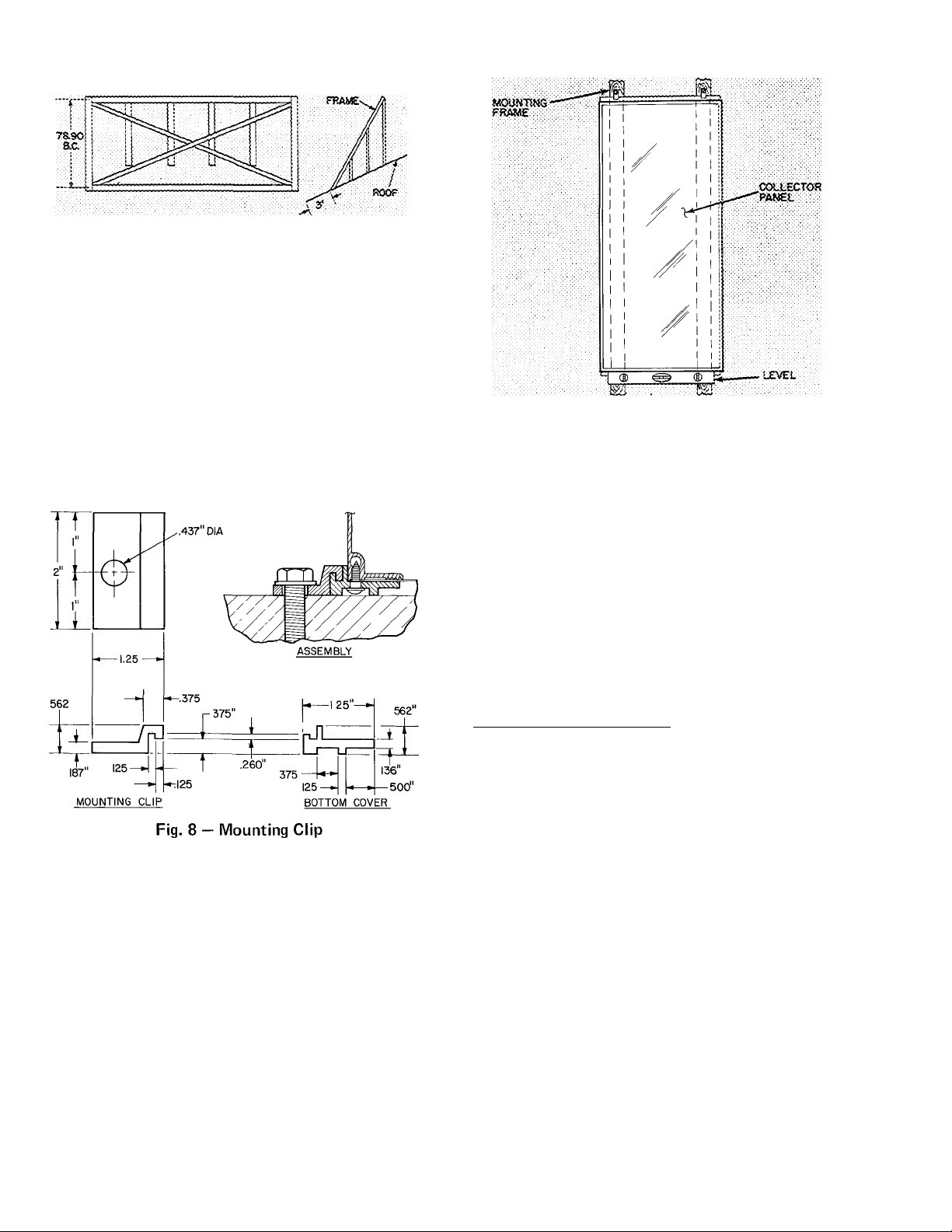
Fig. 7 — Typical Collector Mounting Frame
MOUNT THE COLLECTORS on completed frame
or sleepers. Lasten in place with four mounting
clips supplied with each collector. Use 2 clips on
each end of the collector. See Fig. 8. Each clip has
a .437-in. diameter hole to accept a field supplied
mounting screw. Use a level to align the collectors
exactly parallel to the horizontal plane, Fig. 9.
NOTE: There is no fixed top or bottom to a
collector. It can be installed either way,
although it may be preferable to install so
nameplate can be read.
NOTE: Supply and return piping must be sloped
Fig. 9 — Collector Panel Leveling
attached into the collectors and solder the headers
onto the stubs (Fig. 10). Solder the supply and
return lines in place. Install a tee with a pressure
relief valve between the leaving header and 2-1/8
in. return pipe. Use an ASME approved pressure
relief device with a 50 psig set point and a manual
release lever. (See Leak Testing below.)
If it is necessary for return and supply pipes to
penetrate the roof, install a pitch pocket to seal the
opening.
Install the Collector Sensor on an interior collector
panel after headers have been soldered in place.
Sensor location and method of attachment is
described on pg 15.
MAKE PIPING CONNECTIONS - Attach supply
and return piping headers and lines to collectors.
Piping supply line size is specified by Solar CLIC.
Return line is 2-1/8 in. O.D. on all systems. See
Fig. 10. The headers can be completely pre
fabricated. Determine distance between the
collector inlet connections and outlet connections
(35-in. if panels are butted up to each other). Make
headers with regularly spaced T-sections to mate
with the inlet and outlet of the collector array.
Acquire two 3/4-in. MPT to 3/4-in. sweat
copper fittings for each collector. To each fitting,
solder (95-5) a 3/4-in. copper pipe stub of appro
priate length to maintain a minimum vertical
1/4-in. slope/ft of header. It might be necessary to
bend the copper stubs to maintain this vertical
slope. Thread the fittings with copper stub
LEAK TEST THE COLLECTOR ARRAY ^ Using
city or well water with a minimum pressure of 30
psig, leak test the collectors and piping as follows;
;a. Soft solder (50-50) a temporary cap or end of
2-1 /8 in. collector return line.
b. Attach water supply line to collector supply
pipe.
c. Fill collector array with water using release
lever on pressure relief valve (Fig. 10) to bleed
air from collector system. If relief valve does
not have a manual release lever, temporarily
replace the relief valve with an air bleed valve.
d. Leave water pressure on to system and check
collectors and piping for leaks per local codes.
e. If leaks occur, drain water from system by
removing water pressure source. Repair leak
and repeat steps b, c, d and e.
f. Using a tubing cutter, remove temporary cap
from 2-1/8 in. return line. (This liiie will be
filled with water.)
10
Page 11
COU.SCTOR
‘Enclose exposed frame members to prevent moisture entry and soil effect
Fig. 11 — Lx)cation of Flashing Material
Pf?£SStiR£ RELIE" VALVE
11
Page 12

INSTALL FLASHING, INSULATION AND
FRAME ENCLOSURE after system has been leak
checked. Completely insulate piping with 3/4-in.
closed cell flexible rubber insulation such as
Armaflex or Rubatex. Eiberglass insulation may
also be used, however, any non-rubber insulator
must be waterproofed. Do not leave any portion of
tubing uninsulated or significant heat losses will
result.
Install a flashing over both header assemblies to
make installation weathertight, Fig. 11.
Complete the collector panel installation by
enclosing the exposed sections (ends and back) of
wooden mounting frame. Wind can lift an exposed
frame and dislodge panels. Use 1/4-in. exterior
grade plywood or similar lightweight material. This
provides some protection from wind damage, and
snow buildup.
Step 5a — Install Plain Water Pump Package
specified by Carrier. Review System Requirements,
Pg6.
MOUNT ON FLOOR — Plain water pump and
control package (Fig. 12) can be mounted directly
on a floor. A fixed mounting is not necessary as
the unit’s weight is sufficient to keep the unit in
place. Provide service access at rear, front and
sides of unit. Fig. 2. If the floor on which the unit
is placed is subject to flooding, raise the unit so
that the flood water cannot enter the unit.
MAKE WATER PIPING CONNECTIONS - Use
water grade copper tubing or better. Sweat all
connections and joints with solder (95-5). Tubing
sizes for solar collector piping loop are specified
(by Carrier) for system. (A 2-1/8 in. OD collector
loop return line is used on all systems.) Tubing
sizes for Tri-X coil water loop and domestic water
preheating piping are shown below. Four pipe
connections are required on plain water pump
package, Fig. 2. Typical piping diagrams for com
pleted systems are shown in Fig. 16 and 17.
Collector Loop (Fig. 13) — Begin this loop with a
1-1/8 in. pipe leaving the bottom of the storage
tank. The pipe enters the pump package at the
“storage supply” (second from right) stub. After
passing thru the collector pump, (No. 2), the loop
exits the unit at the “collector supply” stub and
#
LOW VOLTAGE
TERMINAL COMPARTMENT
NON-ADJUSTABLE
AQUASTAT
ADJUSTABLE AQUASTAT
CONTROL
BOX ■
WATER CONN
TO TRI-X
WATER CONN. FROM
STORAGE TANK
(TO BE .HEATED)
WATER CONN
TO SOLAR
COLLECTORS
WATER CONN. FROM
STORAGE TANK
(PROVIDES HEAT)
TRI-X COIL PUMP
(P|)
BALL VALVES
SOLAR COLLECTOR
PANEHS) PUMP (P2)
Fig. 12 — Plain Water Pump Package (Panels Removed)
12
Page 13

travels to the collectors. From here the loop goes
back to the storage tank thru a 2-1/8 in. pipe. This
down pipe terminates above the highest water level
in the storage tank and must have all horizontal
runs of tubing pitched downward a minimum of
1/4-in ./foot.
A pitch of 3/8-in./ft or l/2-in./ft is acceptable
and provides better drainage than 1/4-in./foot. It is
critically important that this pitch be incorporated
into the horizontal runs. It will assure a properly
draining system and will avoid system failures.
The pipe leaving the storage tank must be at
least 6-in. from the bottom of the tank. The run of
pipe to the pump package must not be less than
2 ft below the lowest water level in the tank. This
condition will assure that the collector pump will
have its required prime at all times. Insulate both
collector supply and collector return piping legs.
b. The pipe leaving the storage tank must always
be at least 2 ft below the lowest water level.
c. It is recommended that the 28QX coil be the
highest point in the loop. This will make the
bleed valve on the coil an effective air bleed
port. If it is not possible for the coil to be the
highest point, it will be necessary to add a field
installed air bleed valve at the highest point in
the loop.
d. If the 28QX coil is more than 6 ft above the
water level in the storage tank, it will be
necessary to employ a special fill-up procedure.
This will entail adding a booster pump and
pump fitting in the pipe between the pump
package and the 28QX coil. See the Start-Up
Instructions pg 23 for details concerning this
procedure.
RETURN
■■ ■
TERMitiATt BELOW
LOWEST WATER
LEVEL i
Fig. 13 — Solar Collector Panel(s) Piping Loop
on Plain Water System
28QX (Tri-X) Coh Loop (Fig. 14) - This loop
begins with a 7/8-in. pipe leaving the bottom of the
storage tank and entering the pump package at the
7/8-in. stub labelled “storage supply”. The loop
continues thru the Tri-X pump (P-1) and out the
pump package thru the 7/8-in. stub labelled
“28QX supply.” This pipe enters the Tri-X coil at
the “water in” stub. It exits the coil at the “water
out” stub and goes back to the storage tank (top or
bottom entry).
The pipe size and allowable lengths for the
entire loop are listed below. A value of 4 ft should
be used for the length of tubing inside the pump
package.
ALLOWABLE PIPE LENGTHS
Pipe Q.D. (in.)
7/8
1
1-1/8
Maximum Equivalent Length (ft)
60
120
240
Fig. 14 — Tri-X Coil Piping Loop
on Plain Water System
THERMjSrOfi
tNSL'LATtOK
There is no mounting height restriction on the
Tri-X coil since it is in a closed loop system. There
are, however, other installation restrictions:
a. The termination points of the loop (in storage
tank) must always be below the lowest water
level.
13
(«TERK»
panels
Fig. 15 — Collector Thermistor Location
Page 14

LOCATE AND INSTALL THERMISTOR SEN
SORS AND AQUASTAT BULBS - Located in the
low voltage terminal block compartment of the
control box are 2 thermistor sensors and 3 bulb
wells, Fig. 18.
Two of the bulb wells are to be used with the
aquastat bulbs located on the control box in pump
package, Fig. 12. These wells are to be inserted in
the storage tank so that the aquastat bulbs are
located at the same level in the storage tank as the
outlet to the Tri-X pump. The aquastats are bulb
and capillary refrigerant charged sensors. The
capillary tubes are 20 ft long. Consequently, the
pump package should be placed with this restric
tion in mind.
If it is necessary, the aquastats may be removed
from the control box and mounted close to the
storage tank. If this approach is taken, 14 gauge
wire should be used to connect the aquastat to the
appropriate wires out of the control box.
Thermistor Sensor Mounting — Mount sensors so
that good thermal contact is maintained. A small
amount of G.E. insulgrease #640 (field supplied)
between the sensor and the interior tube of the
solar panel array and also in the well used on the
storage tank sensor is recommended to improve
thermal contact.
Storage Tank Thermistor — The thermistor is not
submersible and should be placed in the remaining
bulb well at the same level in the storage tank as
the outlet to the collector pump.
#
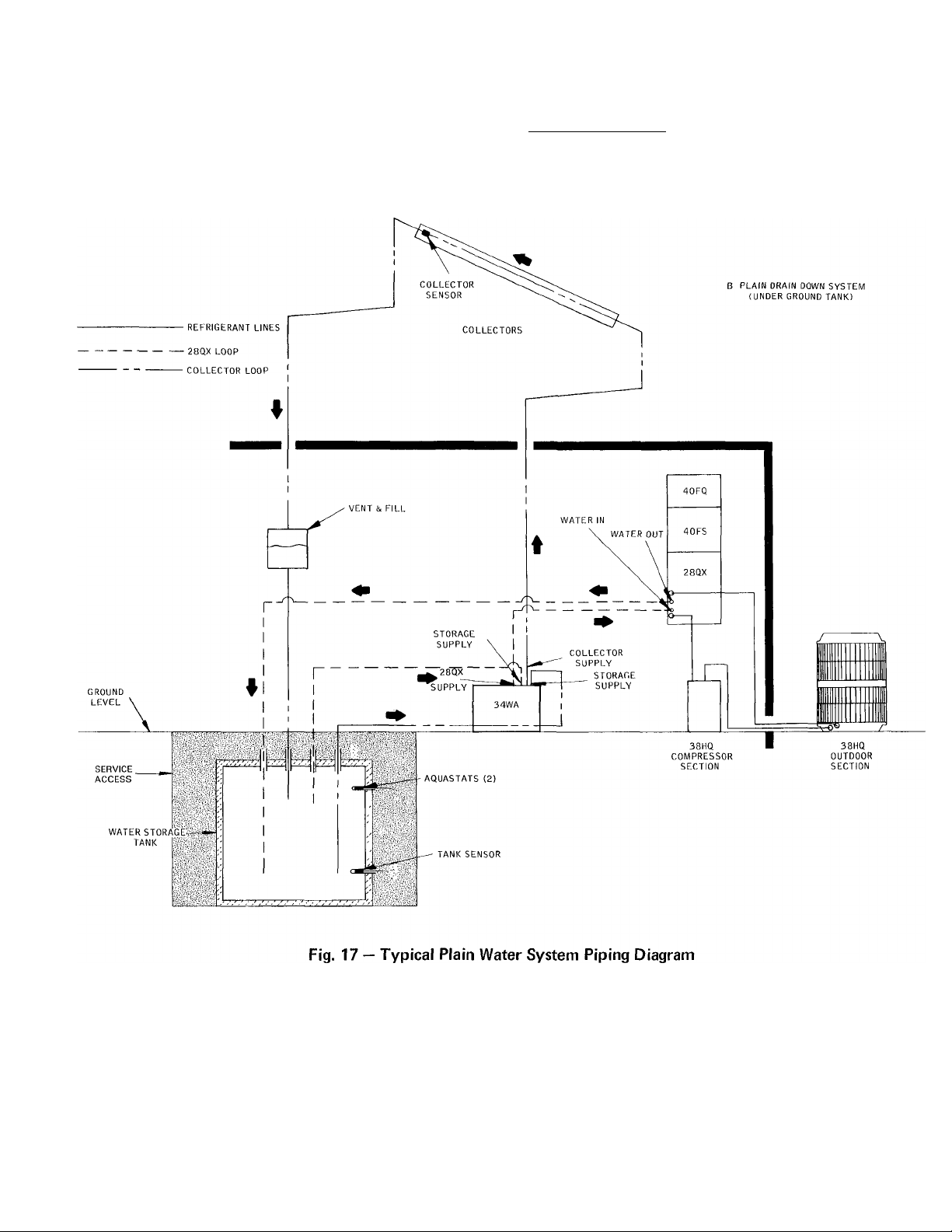
All water supply lines leaving storage must be more than 6-in from bottom of tank but no closer than
2 ft from lowest water level
Fig. 16 — Typical Plain Water System Piping Diagram
14
Page 15
Solar Collector Panel Thermistor ~ The collector
thermistor should be placed on the leaving tube on
an interior panel in the panel array. One of the
interior panels should be used because of reduced
edge losses and higher performance. The thermistor
should be butted up against the panel and secured
in place on the tube with a hose clamp, as
illustrated in Fig. 15. Do not overtighten clamp.
Insulate sensor and tubing.
Thermistor Wiring — (See Electrical Data and
Wiring, pg 20.)
15
Page 16

BULB WELL
WATER CONN TO
STORAGE TANK
GLYCOL/WATER CONN.
TO SOLAR COLLECTORS'
GLYCOL/WATER i
HEAT
EXCHANGER
WATER CONN TO
'TRI-X COIL
, ^ , GLYCOL/WATER CONN. FROM
1 ^
-----
'^OLAR COLLECTORS
THERMISTOR
SENSOR
Fig. 18 — Thermistor Sensor and Bulb Well
HEAT
EXCHANGER
PUMP (P3)
SOLAR
COLLECTOR
PUMP (P2)
WATER CONN. FROM STORAGE
TANK (PROVIDES HEAT)
BALL VALVES
GLYCOL
LEVEL
SIGHT GLASS
Fig. 19 — Glycol Pump Package (Panels Removed)
Step 5b — Install Glycol Pump Package specified
by Carrier. Review System Requirements, pg 6.
The glycol system is composed of the same
components as the plain water system with dif
ferences only in the pump and control package.
Follow same installation requirements and
recommendations indicated for the plain water
system including solar collector and storage tank
installation found in Steps 3 and 4.
MOUNT ON FLOOR — The glycol pump package
(Fig. 19) can be mounted directly on a floor. If the
floor space is subject to flooding, elevate the pump
package so that flood water cannot enter the unit.
Provide service access at the rear, front, top and
sides of unit as shown in Fig. 2.
MAKE WATER/GLYCOL PIPING CONNEC
TIONS — Use water grade copper tubing or better.
Sweat all connections and joints with solder (95-5).
Tubing sizes for solar collector piping loop are
specified (by Carrier) for system. Tubing sizes for
Tri-X, coil water loop, heat exchanger loop and
domestic hot water preheating piping are shown
below. Size pipe connections are required on
Glycol systems. Fig. 2. Typical piping diagrams for
completed systems are shown in Fig. 23 and 24.
Fig. 20 — Solar Collector Panel(s) Piping Loop
on Glycol System
Collector Loop (Fig. 20) — This loop begins at the
“collector return” stub at top of the pump package
(2-1/8 in. O.D. pipe). It travels thru the expansion
tank, pump and heat exchanger and out of the
pump package thru the “collector supply” stub
(1-1/8 in. OD). The glycol travels thru the collec
tors and back thru the drain down pipe to the
beginning of the loop.
16
Page 17

#
Any field installed run of horizontal tubing in
the collector loop must be pitched downward a
minimum of 1/4-in. per foot. A pitch greater than
1/4-in./ft, such as 3/8-in./ft or 1/2-in./ft, is accept
able and better than 1/4-in./ft. This pitch require
ment is critical to the installation because failure to
incorporate this requirement will result in system
failure. A l/4-in./ft pitch (min.) and specified
tubing sizes allow positive liquid drainage.
The size of tubing to be used in the “collector
supply” leg of the loop is specified by Carrier.
Both “collector supply” and “collector return”
legs must be insulated.
Add a field procured and installed component
to the “collector supply” leg of the loop — an
ASME approved pressure relief device with a 50
psig set point (not required on plain water system).
Install in a T-joint in the conditioned space side of
the “collector supply” leg. The device should not
project into the supply leg pipe (see detail A of
Fig. 20).
wa,TER
OUT N
|! ¡[WATERin- , j
eXPAiiSlON
TANK
STORAOE
SUPPLY ■
Fig. 21 — Tri-X Coil Piping Loop on Glycol System
2SQX
SUPPt-Y
SUPPLY
■'I
RETUSN
,, , ,
JU
TERMIMATE
8£L0W
LOWEST
WATE3R LEVEL
28QX (Tri-X) Coil Loop (Fig. 21) — The loop
begins in the storage tank with a pipe at the
bottom of the tank. This pipe exits the tank
bottom and goes to the rear of the pump package
to the left-hand stub labeled “storage supply.” The
loop continues thru a pump and out of the pump
package thru the “28QX supply” stub. The loop
continues to the 28QX coil where it enters at the
“water-in” stub. After traveling thru the coil, the
loop exits at the “water-out” stub of the coil and
returns thru the top or bottom of the storage tank.
(This loop must terminate below the lowest water
level.)
The pipe size and allowable lengths of this loop
are listed below.
ALLOWABLE PIPE LENGTHS
operates in a closed loop system. There are,
however, other restrictions.
a. The termination points of the loop (in storage
tank) must always be below the lowest water
level in the storage tank for the loop to be a
closed system.
b. The beginning point for the pipe that enters the
“storage supply” stub on the pump package
must always be at least 2 ft below the lowest
water level in the storage tank but not less then
6 in. from bottom of tank.
c. It is recommended that the 28QX coil be the
highest part of the loop. This is accomplished
by routing the supply and return pipes below
the coil height level. The reason for having the
28QX coil at the highest point is to make the
air bleed valve in the coil effective. If it is not
possible to route the return and supply lines
below the coil, an air bleed valve (similar to the
one found on the 28QX coil water header) will
have to be installed at the highest point in the
loop.
d. If the 28QX coil is mounted more then 6 ft
above the water level in the storage tank, a
special fill-up procedure will have to be
followed. Details can be found in the Start-Up
Instructions section. However, this procedure
will require a booster pump and booster pump
inlet fitting added to the 28QX supply line
between the pump package and 28QX coil. It
will therefore be necessary to add the booster
pump fitting when installing the 28QX supply
pipe. Refer to the Start-Up Instructions for
details concerning the type of fitting to be
used.
Fig. 22 — Heat Exchanger Piping Loop
on Glycol System
Pipe O.D. (in.) Maximum Equivalent Length (ft)
7/8
1
1-1/8
60
120
240
The pipe length listed is for the entire loop length.
A value of 5 equivalent ft should be used for the
pipe inside the pump package. There is no mount
ing height restriction for the 28QX coil since it
Heat Exchanger Loop (Fig. 22) — This loop begins
in the storage tank. A pipe leaving the bottom of
the storage tank travels to the rear of the pump
package to the right stub labelled “storage supply.”
The loop continues inside the pump package thru
the pump and heat exchanger and exits the unit at
the “storage return” stub. From here, the loop
returns to the top or bottom of the storage tank
(should be below the lowest water level).
17
Page 18

The pipe diameters and the allowable lengths
for this loop are listed below.
is found in the Start-Up Instructions will have to
be followed, pg 23.
ALLOWABLE PIPE LENGTHS
Pipe O.D. (in.) Maximum Equivalent Length (ft)
7/8
1
1-1/8
25
50
100
A value of 8 equivalent ft should be used for the
pipe length inside the glycol pump package.
It is advisable to terminate the storage return
pipe below the lowest water level in the storage
tank. This will make this loop a closed loop and
will assure that no air could infiltrate the loop. It is
important that the height of the return pipe above
the storage water level not exceed 6 feet. If it is
necessary to do so, a special fill-up procedure that
LOCATE AND INSTALL THERMISTOR SEN
SORS AND AQUASTAT BULBS - Located in the
low voltage terminal block compartment of the
control box are 2 thermistor sensors and 3 bulb
wells, Eig. 18.
Two of the bulb wells are to be used with the
aquastat bulbs located on the control box in pump
package. Fig. 12. These wells are to be inserted in
the storage tank so that the aquastat bulbs are
located at the same level in the storage tank as the
outlet to the Tri-X pump. The aquastats are bulb
and capillary refrigerant charged sensors. The
capillary tubes are 20-ft. long. Consequently, the
pump package should be placed with this restric
tion in mind.
All water supply lines leaving storage must be more than 6--in. from bottom of tank, but no closer than
2 ft from lowest water level.
Fig. 23 — Typical Glycol System Piping Diagram
18
Page 19

If it is necessary, the aquastats may be removed
from the control box and mounted close to the
storage tank. If this approach is taken, 14 gauge
wire should be used to connect the aquastat to the
appropriate wires out of the control box.
Thermistor Sensor Mounting — Mount sensors so
that good thermal contact is maintained. A small
amount of G.E. insulgrease #640 (field supplied)
between the sensor and the interior tube of the
solar panel array, and also in the well used on the
storage tank sensor is recommended to improve
thermal contact.
bulb well at the same level in the storage tank as
the outlet to the collector pump.
Solar Collector Panel Thermistor — The collector
thermistor should be placed on the leaving tube on
an interior panel in the panel array. One of the
interior panels should be used because of reduced
edge losses and higher performance. The thermistor
should be butted up against the panel and secured
in place on the tube with a hose clamp, as
illustrated in Fig. 15. Do not overtighten clamp.
Insulate sensor and tubing.
Storage Tank Thermistor — The thermistor is not
submersible and should be placed in the remaining
Thermistor Wiring
Wiring, pg 20.)
(See Electrical Data and
#
Fig. 24 — Typical Glycol System Piping Diagram
19
Page 20

Step 6 — Make Electrical Connections — Field
wiring must comply with local and national fire,
safety and electrical codes. Voltage to units must
be within ± 10% of voltage indicated on nameplate.
Operation of unit on improper line voltage
constitutes abuse and is not covered by Carrier
warranty.
Electrical data for pump packages including
wire and fuse sizes are shown in Table 3. See 38HQ
and 40FS unit Installation Instructions for similar
electrical data. All line and control power wiring
connections for the Solaround"'''^ System are
shown in this booklet. Refer to Pump Package
label wiring diagram, Fig. 25 and 26 and typical
system wiring schematic. Fig. 27. Be sure ther
mistor sensors are wired to terminals in pump
package control box.
INSTALF BRANCH CIRCUIT FUSED DIS
CONNECTS of adequate size to handle unit
starting current. Provide a separate fused dis
connect for each of the following; pump package,
compressor section, indoor fan coil and outdoor
coil section. Locate disconnects within sight of and
readily accessible from the unit, per section 440-14
of National Electrical Code (NEC).
Be sure all ground leads are connected to
grounding lugs provided on units.
CONTROL POWER (24 v) is supplied by indoor
fan coil with 60-va transformer. On 40FQ-25 and
30 kw electric heaters, remove 60-va transformer
and replace with 75-va transformer available from
Carrier Service Parts Center (Part No.
HT01BD235).
Use Carrier accessory room thermostat
HH07AT07 1 with thermostat subbase
HH93AZ069 for proper unit operation.
Warning Logic (WL) Control Wiring Modification Locate WL control in 38HQ compressor section
control box. Move black wire (extended from
low-pressure switch) from WL terminal 2 to WL
terminal 3. This prevents heat pump unit from
restarting when it is shut off by a safety control,
and service is required. The heat pump cannot
restart until thermostat is reset. For instance, if the
heat pump is shut off by 28QX coil freeze
protector, the WL signals a system malfunction by
illuminating a warning light on wall thermostat.
The freeze protector was activated by indoor fan
failure or low refrigerant charge. Either condition
warrants unit servicing before thermostat is reset
and unit is restarted.
Tri-X Coil Wiring — Splice connect 3 wiring leads
to pigtails on 28QX coil freeze-protector (Fig. 25,
26, 27). Use wire nuts and 16 AWG wire (up to
150 ft). Connect leads to pump package terminal
board one.
Thermistor Sensor Wiring — Connect wires from
thermistor on storage tank, and collector panel, to
barrier strip terminals provided on pump package
controller. Use 18 AWG wire for lengths up to
50 ft; 14 AWG wire for lengths up to 250 ft. Use
wire nuts for pigtail connections on thermistors.
Table 3 — Electrical Data (60-Hz)
PUMP
PACKAGE
34WA167
34WA257
34WA367
34GL167
34GL257
34GL367
FLA — Full Load Amps
‘Permissible limits of the voltage range (for limited period of time) at
which the units will operate satisfactorily.
•(-Required when using nonmetallic conduit.
:j;Maximum dual element fuse size.
V/PH
115/1 126
OPER
VOLT*
Max Min
104
Power Wire
Size (AWG)
2 5 14
5.8
8 0 . 12
3 3
6.6
8.8
• 14 48
NOTES: 1
Max Ft
Wire
14
14
12 27
All units have 24-v control circuit which requires ex
ternal power source.
2.
Copper wire size in table based on 60 C. Use copper or
copper-clad aluminum wire. Use latest National Electri
cal Code (NEC) for wire sizing.
BRANCI
63
26
30
24
■1 CIRCUIT
Gnd Wire
Sizet (AWG)
14
14
14
14
14
14
Max Pus
Ampst
■|5
15
25
15
15
25
20
Page 21
FIELD. _
POWER
SUPPLY- RI
BLK
SCHEMATIC DIAGRAM
- WHT
#
—^ K^'
---------
T R6
•® —
ORN
24 V
POWER
—REO —(D^-KD
CONN.
©“-liLU
---------------VIO
----------------
- BRN
BLU '
0--YEL ■
T6 2
-RED
—BLK
~YEL
(^BLU
-------
i^BLK --_
0 - ORN —©H h©----------------------------
®-
1 BLK
Ki)^ RED
—G)H h®— ORN
I----p
R4 W..-W R2
(T^H®
------------------
------------
1
------
YLL—
'"EL
------
<5^T+-(i)-|
------------
RI RI ^ " N—-/ AUUH3 IA I
—(^ H0H®
-----------------------------
•i.
R8 T
<Z>^K^
ORN -0-1 h0
-(Dh I-®-
BLK
-------------
;LU AQUASTAT 90° T- ^
120
AQUASTAT
0<©>®><a)0(^OI
--
BRN—¿)@(^0I
—(D©^^
------------- I—Bl
#
COMPONENT ARRANGEMENT
® 3
®
®| ®
©
® «S
®| ®
® ®
s® ®
®o
I-®®®®
® ®
R 1 R2
-LEGEND TO INDICATE COMMON POTENTIAL ONLY
NOT TO REPRESENT WIRE
FIELD POWER WIRING
FIELD CONTROL WIRING
FIELD SPLICE
COMPONENT CONNECTION (MARKED)
o
COMPONENT CONNECTION (UNMARKED)
o
JUNCTION
PUMP, TRI-X COIL
PUMP,COLLECTOR
RELAY
TERMINAL BLOCK
TEMPERATURE DIFFERENTIAL
FREEZE PROTECTOR
© @ ®
AQUASTAT orn/^
1WA3671000NLY -/ "EO ®‘i° Rtt
--------
WHT OR BLU —’I 11
TB 3
® €>
R3
®®
® ®
R4
®®®
® ®
R7
q
34WA167100
34WA257100
34WA367100
COIL SECT.
280X036
OR
OR
280X042
NOTES:
1, PUMP MOTORS THERMALLY PROTECTED
2 USE COPPER OR COPPER-CLAD ALUMINUM
CONDUCTORS ONLY
SENSORS REMOTELY LOCATED, SHOWN FOR
CONNECTING POINTS ONLY
©
3
®®
‘W
I
disconnect! /
I PER N E C K WIRING
1 I ■ * I MI
' ! M !
utr^m-a
FOR use WITH
38HQ120
38H0960
38HQ127, 134
38HQ940
38HQ140
38HQ960
I34WA500074 |REV. B
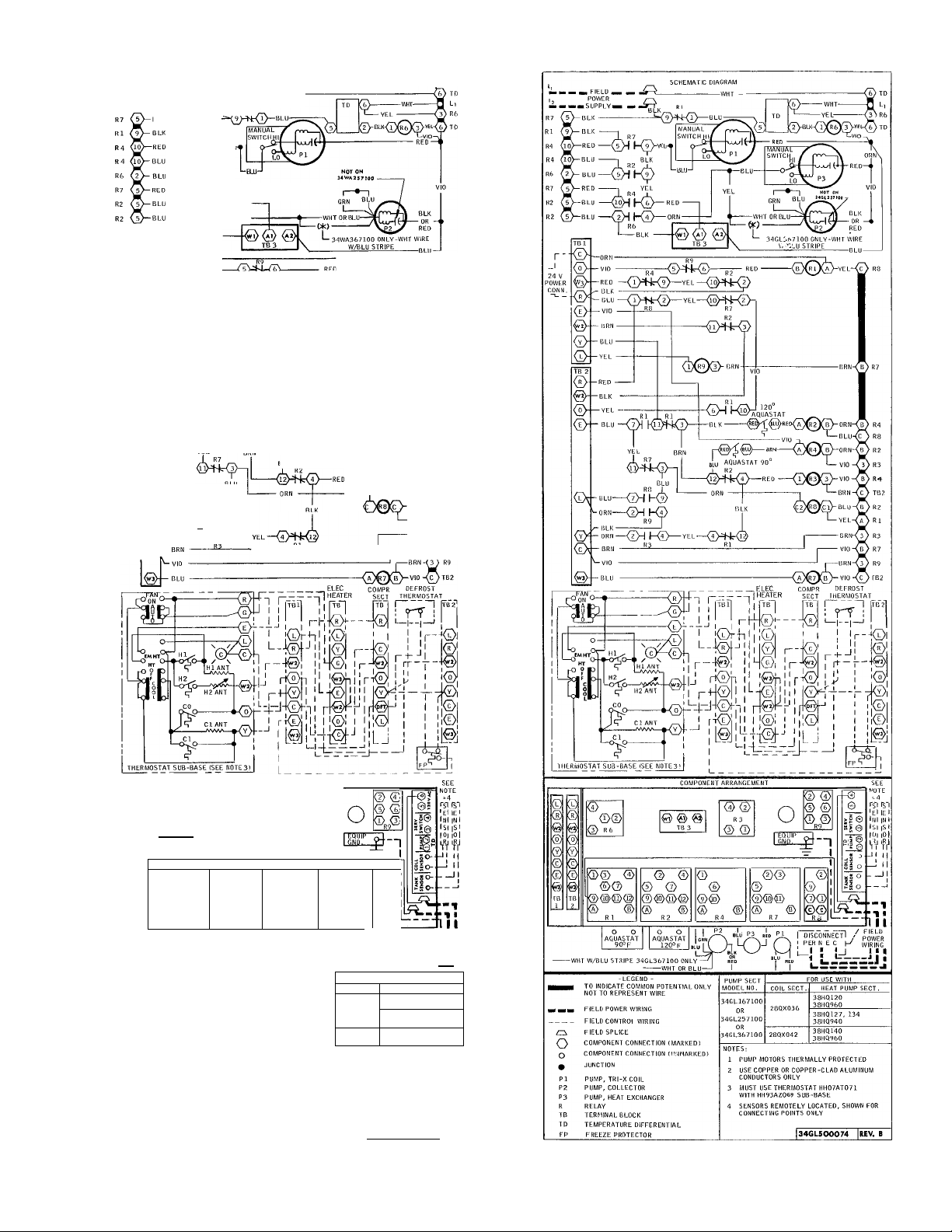
Fig. 25 — Label Diagram; 34WA167,257,367;
115-1-60
HEAT PUMP SECT.
Fig. 26 - Label Diagram; 34GLI67,257,367;
115-1-60
21
Page 22
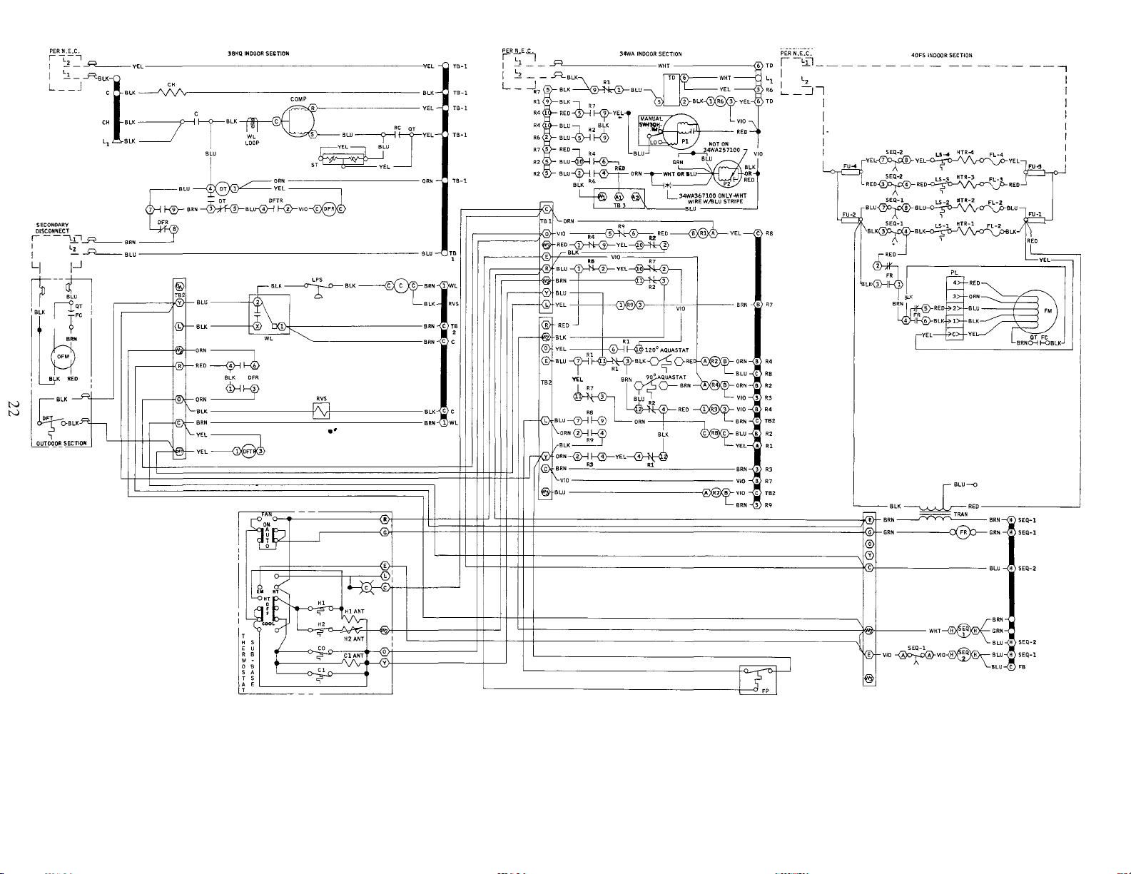
DISCONNECT
Fig. 27 — Typical System Wiring
Page 23

#
INITIAL START-UP
Follow this start-up procedure since a proper
start-up is essential to efficient and reliable system
operation. Review Start-Up data in 38HQ heat
pump Installation Instructions and Refrigerant
Charging on pg 27 of this publication.
Plain Water System Start-Up — At this stage of the
installation, all components should be in place, all
piping connections made and all power and low
voltage wires connected. The fused disconnect
should still be in the OFF position. Leave the
disconnect in the OFF position until the procedure
directs otherwise.
SOLAR COLLECTOR PIPING LOOP ^ Begin
filling the storage tank with water. Tap water can
be used as long as dissolved solids do not exceed
800 ppm. Check the storage tank for leaks, espe
cially the area where supply pipes leave tank. Do
not completely insulate the storage tank until it
has been determined that the tank is leak tight.
Complete the insulation of tank. Add the field-
supplied inhibitor to the storage water. See pg 25.
Before start-up, lubricate collector pump (P2)
bearings on pump package models 34WA257 and
34WA367. Follow oiling instructions on oil tube
and oil warning tag attached to pump. The pump
requires yearly maintenance. Remove shipping
strap from pump on 34WA257 models only.
Fill storage tank until water level is higher than
the highest point in the supply line. Be sure pump
package ball valves and isolation valves are still at
factory set open position (screw heads parallel to
piping). To be sure the pump volute is flooded,
open the uppermost air bleed screw (on pump)
shown below. When water runs thru screw hole, all
the air has been bled out and the screws can be
tightened. Collector pump on 38WA167 does not
trap air and bleeding is not required.
Switch on pump package fused disconnect. If
the sun is out, collector pump will start. If the sun
is not out or water in storage tank is warm, start
the pump by disconnecting one of the collector
sensor leads from the differential control (in pump
sensor lead) and listen (at pipe between pump and
collectors) for the water to drain back. Visually
inspect entire system for water traps.
TRI-X COIL LOOP - Bleed air from loop. The air
bleed valve is found at the top of the leaving water
header on the Tri-X coil (or at the highest point in
the loop; see “Tri-X Coil Loop” on pg 13). The
bleed valve consists of a screw in a body with an
exit tube as shown below.
SCREW
EXIT TUBE
By loosening the screw 2 or 3 turns, a path
from the header interior to the exit tube is created.
After loosening the screw, energize the Tri-X pump
by placing a jumper wire between terminals Wi
and A] of Terminal Board 3. Air will make a
hissing sound as it is pushed out of the bleed valve
by the advancing water. When a spout of water
leaves the exit tube, close the screw on the bleed
valve. De-energize the Tri-X pump after allowing it
to run a few minutes with the bleed valve closed.
Repeat the air bleed procedure at a later time
(one-half hour) to be sure all the air is out of the
loop.
Special Water Fill-Up Procedure is required when
the 28QX is mounted more than 6-ft above the
water level in storage tank. (Procedure is same for
plain water or glycol systems.) In these closed loop
circulation systems, the circulator pump does not
have sufficient lift potential to initially fill the piping
loop.
package control box). With pump running, check
piping loop for leaks. Determine whether the
system drains properly by shutting off collector
pump, (shut off power or reconnect collector
Fig. 28 — Booster Pump Application
Be sure the storage tank is full of water.
Temporarily add a booster pump to the piping
loop. Locate the pump to discharge thru a gate
valve installed in water line between pump package
and 28QX coil. Fig. 28. (If pump is not available, a
garden hose operating at city water pressure can be
used.) Before starting pump, close the ball valve on
the flange of factory circulator pump. Fig. 12 and
23
Page 24
19. This will prevent booster pump from filling
storage tank. Open air bleed valve on top of 28QX
coil, start pump and fill piping loop with water.
If 28QX is not at highest point in the water
loop, install an air bleed valve at high point in loop
to purge air. After loop is filled, remove booster
pump and open ball valve in pump package.
CONTROL ADJUSTMENTS ^ The aquastat with
the adjustment knob on the side of the control box
must be set. It must be set to the value that is
specified by the Solar Clic Program. Room ther
mostat adjustment is same as in 38HQ Heat Pump
Installation Booklet.
Glycol System Start-Up — At this point, all
components should be in place and all piping and
electrical connections should be made. The storage
tank should not yet be insulated, and the fused
disconnect should be off. Begin filling the storage
tank as is described in the “Plain Water System
Start-Up” under “Collector Loop.” Check the tank
for leaks, especially at the tank fittings and add the
inhibitor, pg 25.
SOLAR COLLECTOR PIPING LOOP - If the
34GL257 or 34GL367 has been installed, the
collector pump must be oiled with the factory
supplied tube of oil. Follow the oiling instructions
on the oil tube and the oil warning tag. If the
34GL257 has been installed, remove the shipping
bracket from the collector pump.
The expansion tank (Fig. 12 and 19) in the
collector loop will require the addition of a
glycol-water mixture. Standard automotive anti
freeze (Dow, Prestone, Peak, etc.) will be used as
the glycol source. Determine what percentage of
glycol is proper for the particular application using
the glycol manufacturer’s data. Use the glycol
charging chart to determine the total amount of
glycol-water mixture required. Add the required
amount to the expansion tank using the hole in the
top of the tank and a funnel as entry into the tank
(Fig. 29). If the glycol charging chart requires more
than 18 gal. (the capacity of the expansion tank),
add as much as possible and save the remainder to
be added after the collector pump is operating.
Bleed the air out of the collector pump (34GL257
and 34GL367 only) as described in the “Collector
Loop” section of the “Plain Water System
Start-Up” procedure.
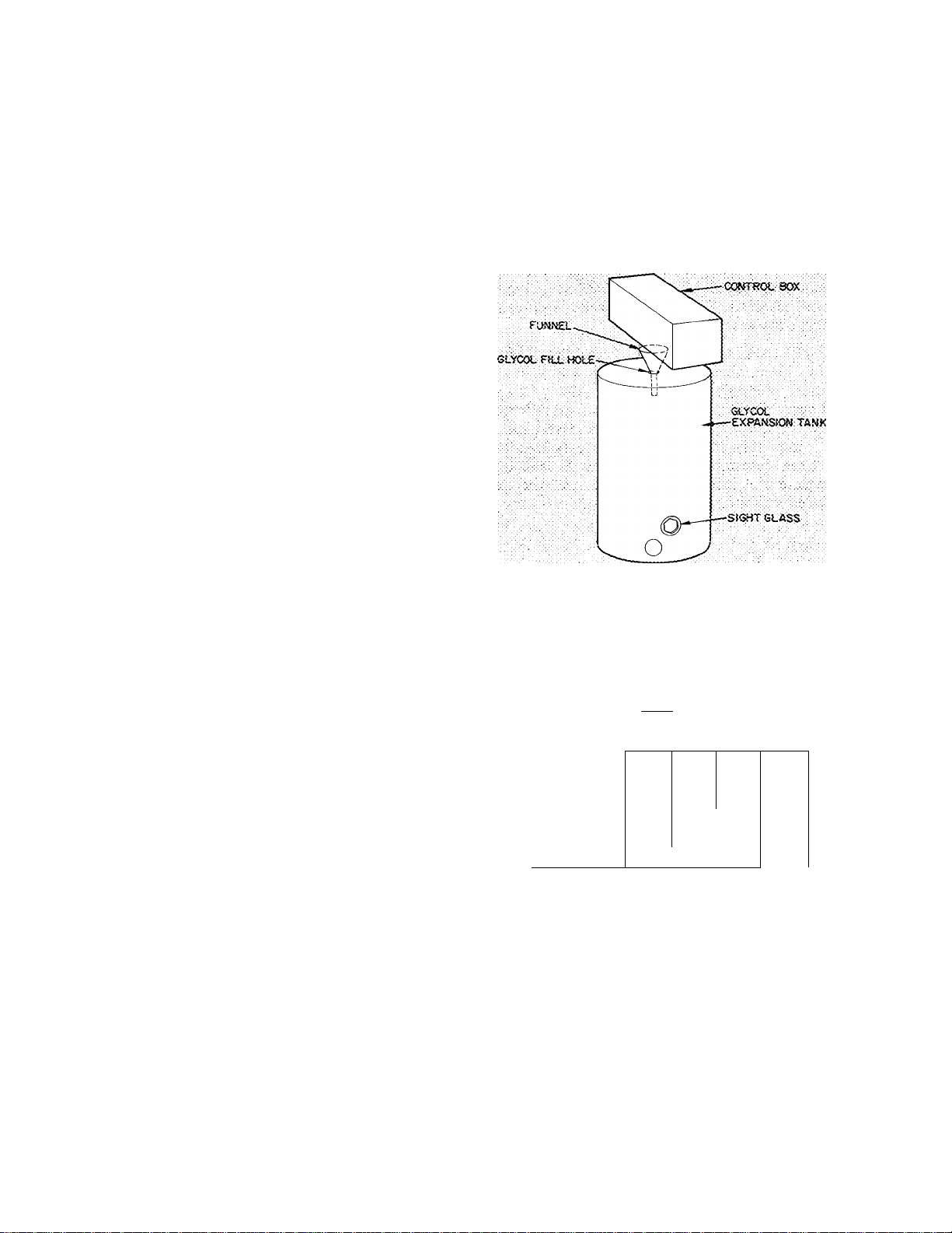
Before starting collector pump locate sight glass
at bottom of expansion tank (Fig. 29). The sight
glass is for checking glycol level in tank when
collector pump is operating. If glycol level falls
below the sight glass, collector pump inlet takes in
air and pump won’t function properly. If complete
glycol-water charge was not all added initially, it
can be added when collector pump is started and
space in expansion tank becomes available.
Switch on fused disconnect to energize col
lector pump. (Follow procedure outlined in the
“Collector Loop” section of the “Plain Water
System Start-Up” instructions.) Determine that
collector piping loop is leak tight and then shut off
collector pump. After shutdown, look thru hole in
top of expansion tank to be sure the glycol drains
back.
Fig. 29 — Filling Expansion Tank
Table 4 — Glycol Charging Chart
Lineal Ft of Piping
from Collector Pump
to Collectors
10
20
30
40
50
60
When glycol/water charge is over 18 gal., the remainder
must be added after collector pump is operating
TOTAL NO. OF COLLECTORS
15
20
21
.1.
,,, : 19
25
18
22
23
10
Glycol/Water Mixture (Gal.)
11
13 15 17
13 14 16
14 16
15 17
16 .18
„JS...
J 19 20
1 20
5 "l9
TRI-X COIL LOOP - Follow the procedure
outlined in the “Tri-X Loop” section of the “Plain
Water System Start-Up” instructions.
HEAT EXCHANGER LOOP - Since the heat
exchanger pump is electrically parallel to the
collector pump, it has already run. However, if the
heat exchanger loop is a closed one, bleed the air
out of the loop. If the loop is an open one (the
return pipe is not below the water’s lowest level in
storage tank), the bleed procedure does not have to
be followed. To bleed the closed loop, loosen the
bleed screw at the top of the heat exchanger as
shown in Fig. 30.
24
Page 25
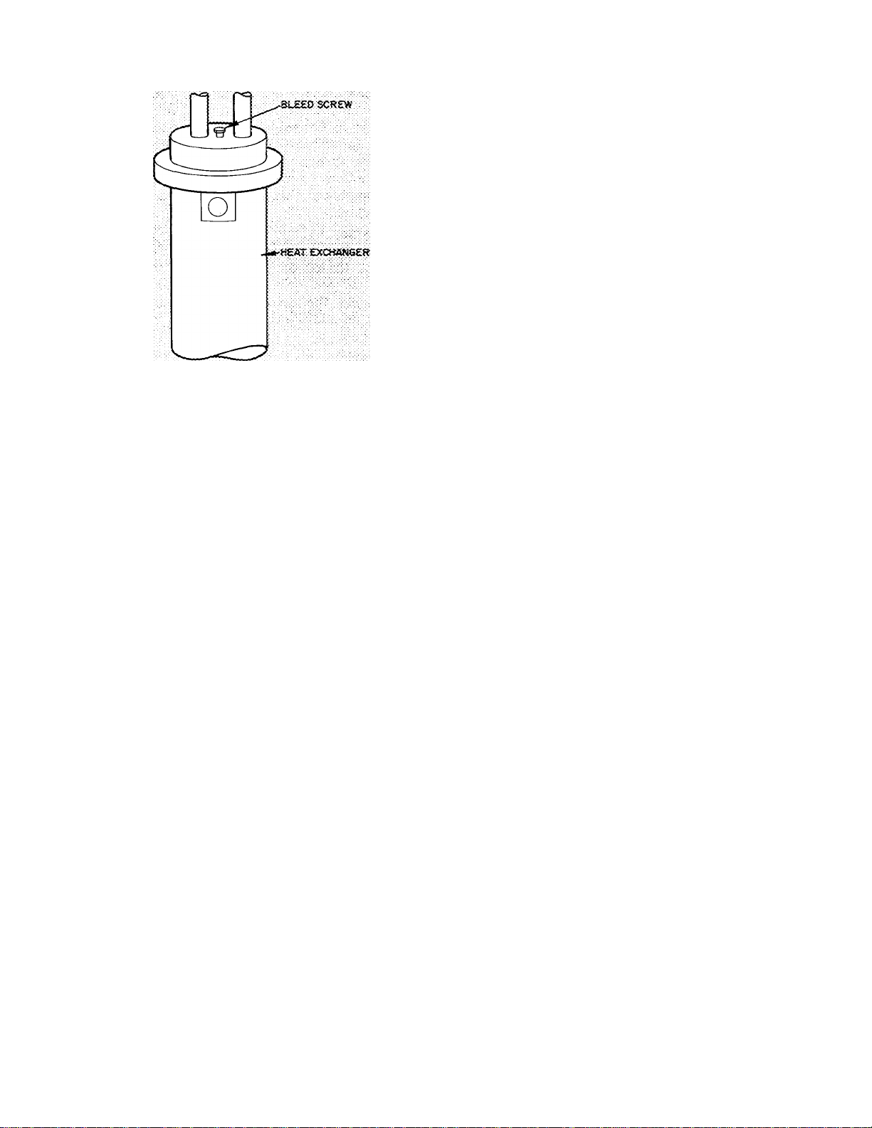
Fig. 30 — Bleed Screw Position
Run the heat exchanger pump by energizing the
collector loop. When the air has been bled, tighten
the screw.
CONTROL ADJUSTMENTS - The same control
timing on the adjustable aquastat must be made
here as was the case for the plain water system. See
the section on “Control Adjustments” in the
“Plain Water System Start-Up” instructions for
details.
Inhibitors (Field Supplied) — Procure an inhibitor
from local water treatment firm. Specify an
inhibitor of fungus, rust, scale, red water and
galvanic action. The stored fluid passes thru many
parts of the Solaround''''''' System composed of
different materials, each vulnerable to the effects
of these natural and chemical actions.
Add inhibitors to the water charge in thermal
storage tank. Tap water may be used if total
dissolved solids do not exceed 800 ppm. Other
wise, dilute tap water with demineralized water to
reduce sohds below that level.
If the system is charged with antifreeze,
commercial automotive antifreeze solutions should
be used at 50% concentration to obtain the proper
inhibitor concentration.
Inhibitors will be depleted with time to a level
which may even increase corrosion rated beyond
that expected with uninhibited water. Therefore,
make bi-annual checks to test the inhibitor
strength, or replace the inhibitor, following the
manufacturer’s recommendation.
Suitable inhibitors for tap water are as follows:
1. For all copper piping systems with coated
concrete or fiberglass reinforced plastic storage
vessles, or steel vessels with plastic or rubber
liners:
NALCO 7SN-196 or equivalent. See specifica
tion below.
Dosage: 1/4 lb per 1000 gallons (30 ppm).
2. For systems with uncoated steel tanks plus
copper piping:
NALCO 2532 or equivalent. See specification
below.
Dosage: 2 oz per gallon.
NALCO 7SN-196 is in a highly soluble, pulverized
form.
Color............................................................White
Odor ............................................................ None
Density .............................................67 Ib/cu ft
pH of 1 % Solution ....................................... 12.3
Solubility in Water @ 75°F . . . . Up to an 8%
clear solution
Si02
..............................................................
30%
PO4................................................................ 25%
Very slightly hygroscopic
NALCO 2532 is a water soluble, blended liquid
product containing quaternary amine and organotin compounds with the following properties:
Color.................................................Light yellow
Odor ..............................................................Mild
Specific Gravity (@ 25°C)
Density (@ 25°C)
Freeze Point
Flash Point
...................................................
...............................
............................................
........................
8.46 Ib/gal
1.016
— 1.0°C
None
pH (Neat)....................................................... 12.2
Do not apply to potable water or domestic
water systems. Apply this product only as
specified.
Solar-Assisted Heat Pump Operating Modes
System Equipment:
1. Pump Package (34 WA/GL)
2. Compressor and O.D. Coil (38HQ)
3. Tri-X Coil (28QX)
4. Indoor Fan and Electric Heater (40FS/FQ)
5. Solar Collector Panels
MODE: SOLAR ENERGY COLLECTION
Controlling Mechanism:
• Solid State differential controller located in
pump package control box. Two thermistor
temperature sensors are remotely located. One
sensing collector panel temperature (Tc) and
the other sensing storage tank temperature (Ts).
25
Page 26

• The collector circuit pump is operated thru a
relay (Rh) which is activated by the differential
controller. The differential controller monitors
the difference in thermistor temperatures (AT =
Tc — Ts). When this AT reaches 20 F, Rg is
energized, and the collector pump runs (also
the heat exchanger pump in the GL models). If
the pump is running and the AT drops to less
than 5 F, R6 is de-energized and the pump(s)
shut down.
MODE: HEATING
Controlling Mechanism:
• 2-stage room thermostat
Located in
90° Non-adjustable Aquastat storage tank.
Senses water
125 Adjustable Aquastat temperature to
Tri-X Coil.
• The 90° aquastat is factory set.
• The 125° adjustable aquastat should be set
(between 95-125)* in the field as specified by
solar CLIC. (The set point is temperature at
which the QX coil water capacity can satisfy
the house heating design load.)
CAUTION; Do not set adjustable aquastat
above 125 F. Higher temperature can reduce
compressor life,
• The following chart defines the heating modes
as a function of water temperature (aquastats)
and room thermostat stages.
WATER TEMP
Above 125* F
(adjustable aqua
stat set point)
Below 1255^F& ■
Above 90 F
(Non-adjustable
aquastat set
point)
Below 90 F
(Non-adjustable
aquastat set
point)
I. Solar Only
li. Solar and Heat
III. Heat Pump Only
THERMOSTAT
1st Stage
- Tri-X Pump and
Indoor Fan On
Pump
— Tri-X Pump,
Compr., Outdoor
and Indoor Fan
On
~ Compr., Indoor
and Outdoor Fan
On
2nd Stage
No Action
Strip Heat
Strip Heat
MODE; COOLING
The cooling modes are same as the 38HQ heat
pump system cooling operation with one excep
tion. When the thermostat is in the cool position,
the differential controller is locked out; conse
quently, the collector pump(s) will not run during
the cooling season. (When the domestic hot water
accessory is installed, this exception does not
apply.)
MODE: EREEZE PROTECTION OPERATION
The freeze protector is a thermostat placed on the
liquid line in the QX coil. It trips at 31 E and will
reset at 46 F. Consequently, the device can only
function in the following modes: defrost and
cooling. In each of these modes the freeze pro
tector functions to prevent the coil from freezing,
but accomplishes this in different ways, as de
scribed below:
Defrost cycle:
If the freeze protector trips, the Tri-X pump
will be turned on. The only way the defrost
cycle of the heat pump is affected is by
enhancing the defrost performance, by pro
viding an additional source of heat besides the
indoor air.
Cooling cycle:
If the freeze protector trips, the compressor is
turned off and locked off until the thermostat is
reset. If the freeze protector does trip in
cooling, it is an indication of improper system
operation. This could be insufficient indoor air
or low refrigerant charge.
MAIIMTEiSIANCE AND SERVICE DATA
Pump Package
1. 34WA257/367 and 34GL257/367
a. Oil the Bell and Gossett collector (P2 —
Fig. 12 and 19)
• On start up and once a year
b. There is no maintenance required on the
Grundfos(Pi or?3 — Fig. 12 and 19) pumps.
2. 34GL167/257/367
a. Glycol level during operation
• On start-up charge the system with
enough glycol so that the level does not
drop below the sight glass during
collector pump operation.
• Check glycol level at least once a year
during collector pump operation.
b. Check inhibitor effectiveness in glycol once
a year.
Heat Pump, Indoor and Outdoor Fan and Coil,
Electric Heater and Storage Tank
1. Indoor components
a. Replace the filter once a year, sooner if it
becomes excessively dirty.
b. The 28QX036/042 should be checked and
bled of air as specified in the Start-Up
Instructions. This process should be per
formed once a year.
c. When necessary to drain the water from
Tri-X coil, apply compressed air to the coil
water headers. Direct the air alternately thru
the entering water header and then the
26
Page 27
leaving water header in approximately 60second intervals. Using this method will
remove most of water in coil circuits.
d. See fan section, electric heater, or the
compressor section Installation, Start-Up
and Service Instructions for scheduled
maintenance.
STORAGE TANK
e. As specified in the Start-Up Instructions, an
inhibitor must be added to the water in the
storage tank to prevent corrosion. Since this
is an open system, it is very important that
the effectiveness of the inhibitor is main
tained. (See Inhibitor Manufacturer’s
Instructions).
2. Outdoor components
The 38HQ940/960 coil should be cleaned
annually or as often as required.
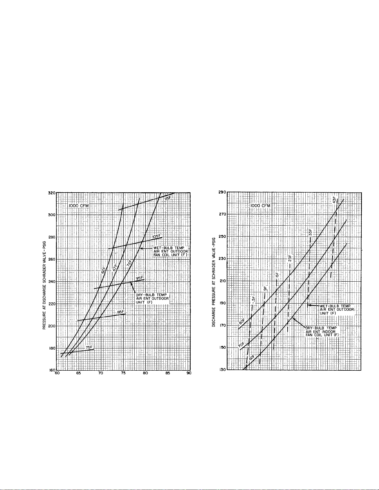
REFRIGERANT CHARGING - The 38HQ out
door fan coil unit contains correct operating charge
for complete system. Refer to 38HQ Unit Installa
tion, Start-Up and Service booklet for refrigerant
charging method details. Cooling cycle charging
charts and heating cycle operation check charts for
38HQ/28QX systems are included in this booklet.
Fig. 31 thru 36.
CAUTION: Rapid, removal of Refrigeran.t-22
charge from heat pump system can <3ro;p pre.ssure and lower temperature and can cause water
in tire Tri~X coil to freeze and split coil tubes.
When necessary for servicing, remove ciiarge
very slowly to minimize possibility of freeze
dajnage.
PRESSURE AT SUCTION SCHRADER VALVE-PSIG
Fig. 31 - 38HQ127/38HQ940 with 28QX036
Cooling Cycle Charging Chart
27
20 30 40 50 60
SUCTION PRESSURE AT SCHRADER VALVE-PSIG
Fig. 32 - 38HQ127/38HQ940 with 28QX940
Heating Cycle Operation Check Chart
70
Page 28

Fig. 33 - 38HQ134/38HQ940 with 28QX036
Cooling Cycle Charging Chart
Fig. 35 - 38HQ140/38HQ960 with 28QX042
Cooling Cycle Charging Chart
20 30 40 50 60
SUCTION PRESSURE AT SCHRADER VALVE-PSIG
Fig. 34 - 38HQ134/38HQ940 with 28QX036
Heating Cycle Operation Check Chart
70
Fig. 36 - 38HQ140/38HQ960 with 280X042
Heating Cycle Charging Chart
28
Page 29
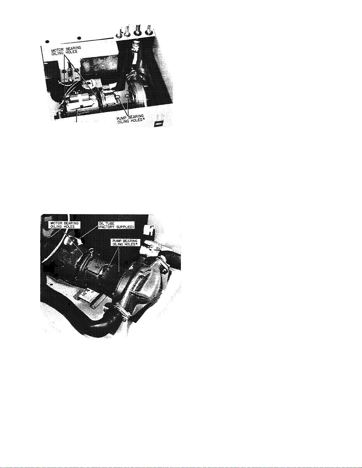
ltoT^;SUPPUEO>
*On 38WA/GL367 Models, remove sheet metal plate for access
to oil reservoir
Fig. 37 — Oiling Hole Location —
Plain Water Pump Package
Start-Up and Annual Preventive Maintenance
Checklist
PUMP PACKAGE
1. Oil Bell and Gosset pump at start-up and
annually (Grundfos pumps are water lubricated
and do not need lubrication).
• Two oilers on each end of motor (Fig. 37
and 38)
• 34WA/GL367 models have sheet metal plate
over oil reservoir; remove plate and add oil
until it comes out bleed hole on side.
34WA/GL267 models have oil tube over
reservoir; fill until oil comes out bleed hole
on side.
2. Inspect for leaks.
3. Make sure ball valves are open on ends of all
Grundfos pumps; screw head should be parallel
to piping.
4. Make sure adjustable aquastat is set properly
(no higher than 125 F).
5. Check glycol level on 34GL systems. It should
be visible in sightglass when operating, if not,
add glycol to bring level up to center of
sightglass.
6. Make sure Grundfos pumps are on high speed.
Switch should be set at #2.
*On 38WA/GL367 Models, remove sheet metal plate for access
to oil reservoir
Fig. 38 — Oiling Hole Location —
Glycol Pump Package
7. Check insulation.
STORAGE TANK
1. Check inhibitor strength. Contact local water
treatment firm. Add inhibitor if necessary.
2. Check to see that insulation has not been
damaged.
3. Check for leaks.
4. Check water level in storage tank' visual
inspection.
5. Check for sediment in bottom of tank. Drain
should be located in supply line with supply
outlet at least 6-in. above bottom of tank.
Release water from drain; if this water has
sediment in it, drain tank completely and clean.
6. Make sure sensing bulbs are tight in wells and
that bulb wells are leak tight.
7. Make sure vent tube is clear and not damaged
or obstructed.
29
Page 30

40FS INDOOR AIR HANDLER AND HEAT
PUMP UNIT
1. Run Refrigerant System Performance check.
2. Refer to appropriate instructions for further
details.
28QX INDOOR COIL
1.
Inspect and clean if necessary.
2.
Change filter or clean with water and detergent
if filter is of permanent type.
3.
Check freeze-up protector. It should be secure
and well insulated.
4.
Open bleed valve on 28QX till water comes out.
This will purge air from system. If 28QX is not
at highest point in system, open field installed
valve.
5.
Make sure all water pipes are fully insulated.
SOLAR PANELS
1. Clean and inspect glass for damage.
2. Inspect panels and associated piping for leaks.
3. Make sure that insulation on piping is in good
condition.
4. Inspect condition of framing:
• Is it level?
• Are panels at correct angle?
• Is flashing leak tight?
• Is frame secure to structure?
5. Make sure collector sensor is secure and well
insulated.
6. On 34GL systems, there is a pressure relief
valve on the highest point of return piping. Be
sure it is in good condition.
30
Page 31

For replacement items use Carrier Specified Parts.
Manufacturer reserves the right to discontinue, or change at any time, specifications or designs without notice and without incurring obligations.
Book
1
Tab 3d 2d
4
Form28QX-lSI New
Printed in U S A
6-78
PC 101
Catalog No 532-816
 Loading...