

Page 1
#
»o
cs
26H
i <
si
3 u
< “
Automatic Icemaker
Dimension Drawings
page 3
page 7
INSTALLATION
AND
SERVICE
INFORMATION
Installation Instructions
Service Instructions page 19
Page 2

-m
Carrier
CARRIER
AUTOMATIC ICEMAKER
SPECIFICATIONS_______________________
DIMENSION DRAWINGS
INSTALLATION
CONTENTS
____-____
_____________
_______________________________________
1. Check Shipment
2. Select Proper Location
3. Move Unit to Location
4. Uncrate the Bin
5. Install Leveling Screv/s
6. Unpack and Mount the Heat Interchanger
7. Move the Bin to Approximate Location....................................
8. Uncrate the Machine Section
9. Remove the Front, Top and Side Panels
10. Plage Machine Section on Top of Bin and Bolt in Position...
I I. Bolt Tie Bar at Rear of Unit................ ...........................................................12
12. Install Water Supply and Drains
13. Make Electrical Connections
14. Install Bin Thermostat Bulb..................................................................
15. Remove the Ice Deflector
16. Install Siphon Standpipe and Adjust Float
17. Replace the Ice Deflector
18. Loosen Compressor Hold Down Bolts
19. Start the Unit
20. Check Operation.................................................................................... 17
21. Final Check List
SERVICE
SERVICE PARTS
___
_______________________________________________________19-61
1. How the Automatic Ice Maker Works
2. Refrigerant Circuit.......................................................................................
3. Freezing Water Circuit
4. Electrical Circuit...........................................................................................
5. Ice Maker Service Checklist
6. Service Analysis 26H5 and 26H3
7. 26H Icemaker Rating Tables
.............
..................................................
......................................
...............................................................
______________________________
- --...................................................................
.........
............
...............................................................................10
............................................................
.......
______
.......
........................................
..........
......................
.........
......................................... .............................
......................................................................... 14
.....
.....................
.................................................................
..............................................................
...................................................................
_____________ ____________
........................
..............................
.................................................
.....
.............
...................................................
.........
.......................................................
.........................................................
____
______
___
...............
.........................
.........
.........................
................
.....................
.........
.........................
.....
..................................
___________________
___
__________ 9-i8
...........
................... 9
...................
............
.......
.....
....................
...............
.....................
_____
..........
..........
....
......
....
.....
.......
.. II
......
.......
......
26H
PAGES
3-6
7,8
9
9
.. 10
10
11
...II
11
12
13
14
14
15
16
16
17
.19
23
36
40
53
54
.60
63-64
All specifications, descriptions, detail drawings, etc.
subject to change without notice or incurring obligation.
1st Printing 7-15-57 5M
1st Reprint 5-15-58 2M
LItho in U.S.A
26H-57PD
Page 3
Carrier^
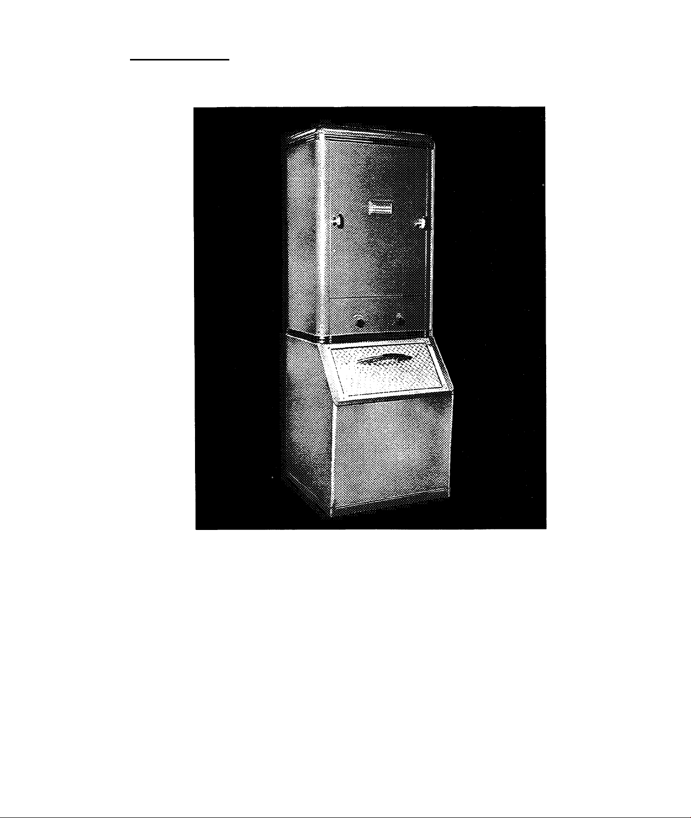
Automatic Icemaker 26H3
#
#
An automatic, low-cost ICE PLANT .
* Produces a continuous supply of ice, cubed or
crushed, automatically.
* Cubes are crystal clear, sanitary . . . untouched
by human hands. Cube's unique shape provides
larger cooling surface.
* Crushed ice delivered in three grades ... to meet
all your sized-ice needs.
* Easily, quickly installed. Requires only standard
electrical and water connections.
* Re-location a simple matter. Just disconnect
water and electricity . . . reinstall in new location.
right in your PLACE of BUSINESS!
* Compact cabinet occupies only 4 sq. ft. floor
area.
* Exterior styled to blend with finest surroundings.
Finished in sea spray green or white, stainless
steel trim.
* Minimum maintenance, maximum quietness . . .
simplified, unique mechanism delivers individually
formed cubes.
* Starts with simple on-off switch. Machine stops
automatically when bin is full, resumes operation
as soon as few cubes are removed.
* Low operating cost . . . efficient, quiet refrigera
tion cycle uses small amounts of water and power.
• Underwriters approved.
3
26H-57PD
Page 4

26H3
SPECIFICATIONS
Carrier
IDEAL for RESTAURANTS, HOTELS, MOTELS, BARS,
TAVERNS, CLUBS, HOSPITALS, DRUG STORES . . .
wherever a continuous supply of clear, sanitary ice,
cubed or crushed, is a tangible business asset. The
Carrier Icemaker freezes and delivers up to 200 pounds
of ice per day, at 90° ambient air and 70° entering
water. Quietly, without complicated cutting or chop
ping mechanism, it provides hard, sparkling cubes
or varied grades of crushed ice. The cube, too, is
designed for highest efficiency ... its unique shape
provides more-than-ordinary cooling surface.
COMPACT, ATTRACTIVE CABINET . . . takes up
only 4 square feet of floor area. Smart, modern design,
featuring rounded corners, o bonder!zed, boked-on
sea spray green or white finish, richly trimmed in
stainless steel and chrome . . . complements any
and all furnishings.
ICE CRUSHER. Entirely automatic, electric-motor
driven unit. Delivers crushed ice in three grades —coarse,
medium, or fine. User sets one control knob to "crushed"
and the other to grade as dictated by needs.
REMOVABLE PANELS provide easy access to working
parts. Access for all normal service through removable
front panel.
WELDED-TYPE HERMETIC COMPRESSOR. Quiet,
efficient, permanently oiled and vibrationless. Designed
for long life and trouble-free operation.
EXCLUSIVE DESIGN ICE-MAKING SYSTEM. NO
MOVING PARTS. Freezing coils are soldered to copper
bands and attached, at 8 different points, to each of 13
stainless steel freezing tubes. In operation, ice builds up
on inside wall of tube at these 8 separate points to form
8 cubes in each tube. Freezing completed, automatic
controls reverse cycle, releasing cubes which simply
"gravity drop" into bin or crusher, as “dialed" by user.
COMPLETELY AUTOMATIC. A simple rotary switch
starts the machine, from then on it produces ice auto
matically. When storage bin fills with cubes, or crushed
ice, the machine shuts off automatically, starting again
whenever some ice is used.
STORAGE BIN (bottom section) available in four
sizes — TOO, 160, 240 and 500 pounds capacity. It
has baked-on finish, stainless steel liner and 2 in
ches of insulation on sides. Partition separates
cubes and crushed ice.
SIPHON-INTERCHANGER. Automatically replaces
the water in the Icemaker system at the end of each
freezing cycle. Pure, crystal clear ice is assured, even in
hard water areas, with a minimum of cleaning and maxi
mum productive capacity.
MECHANICAL SPECIFICATIONS
COMPRESSOR: '/2 horsepower, single cylinder,
welded-type, hermetic compressor, driven by a capaci
tor-start, induction-run motor.
CONDENSER: Water-cooled, shell and finned copper
coil type.
REFRIGERANT: Safe, non-toxic, non-inflammable
FREON-12.
REFRIGERANT CONTROL: Single capillary tube . . .
no moving parts.
WATER PUMP: Stainless steel shaft, brass impeller
and brass housing. Directly connected to a shaded pole,
totally enclosed, thermally protected motor.
POWER CONSUMPTION: 575 watts during freezing.
SWITCH: 3-position rotary ... for manual starting
and stopping, or tor operating of water pump for
cleaning.
CURRENT: 115 volt, 60 cycle, single phase, alternat
ing current.
WATER CONSUMPTION: During freezing, 10 to 42
gallons per hour, depending upon supply water tem
peratures.
DIMENSIONS: 69 inches high, 25 inches deep. Width
is 24 inches with 100 pound storage.
26H3 ICEMAKER WEIGHTS:
Machine section, 100 lb. bin, no crusher, crated 348
Machine section, 100 lb. bin, no crusher, uncrated 305
Ma?hine section, 100 lb. bin, with crusher, crated 388
Machine section, 100 lb. bin, with crusher, uncrated 345
Machine section, 160 lb. bin, no crusher, crated 371
Machine section, 160 lb. bin, no crusher, uncrated 326
Machine section, 160 1b. bin, with crusher, crated 411
Machine section, 160 1b. bin, with crusher, uncrated 366
Machine section, 240 lb. bin, no crusher, crated 405
Machine section, 240 lb. bin, no crusher, uncrated 357
Machine section, 240 lb. bin, with crusher, crated 445
.Machine section, 240 lb. bin, with crusher, uncrated 397
ICE CRUSHER: Cast al uminum rotor, stainless steel
picks, sleeve bearings, belt-driven by a 1/6 horsepower,
drip-proof, thermally protected motor, with adjustable
drive-pulley.
Lbs.
26H-57PD
ÉM
Page 5
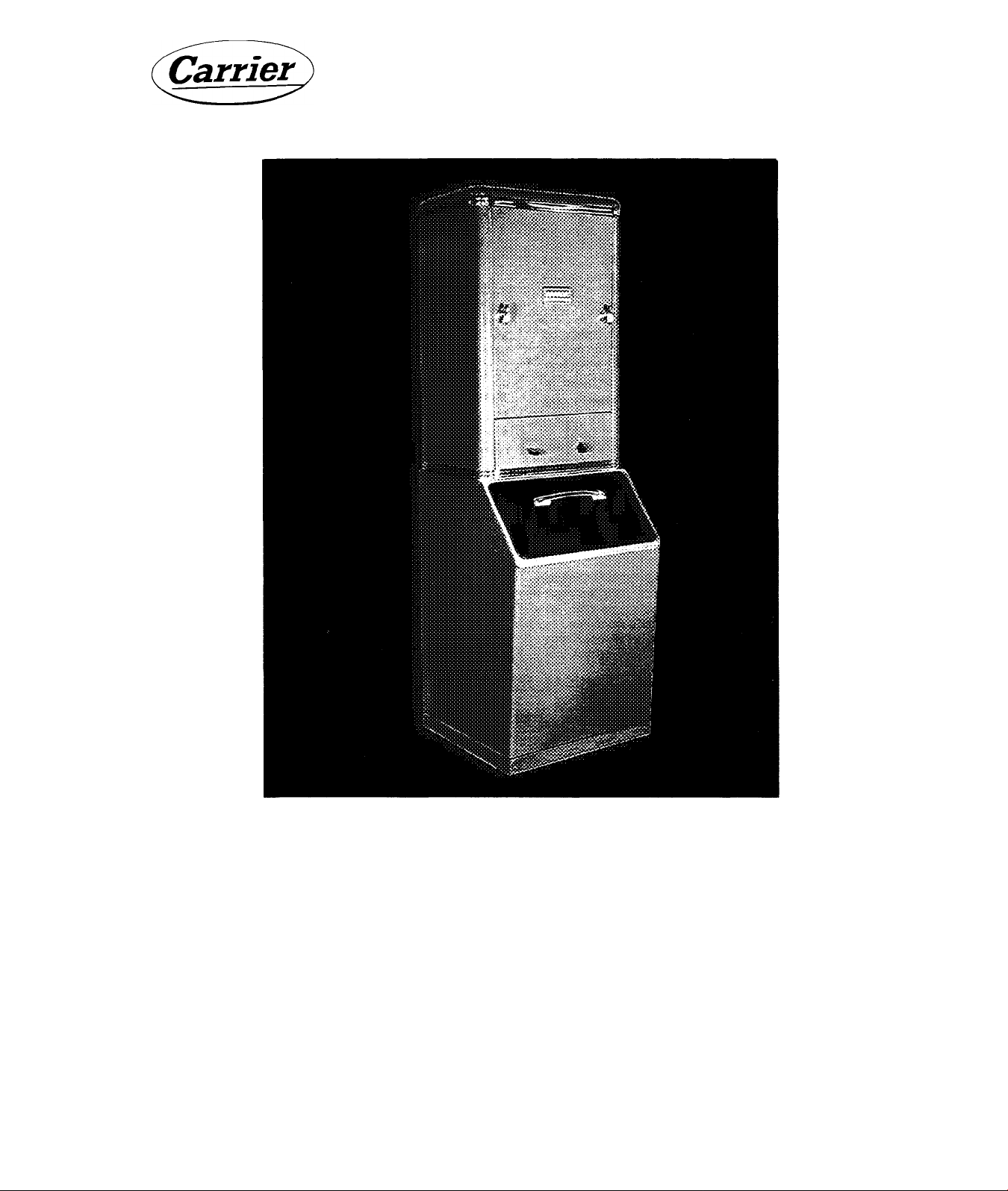
Automatic Icemaker 26H5
An automatic, low-cost ICE PLANT . . . right in your PLACE of BUSINESS!
* Produces a continuous supply of ice, cubed or
crushed, automatically.
* Cubes are crystal clear, sanitary . . . untouched
by human hands. Cube's unique shape provides
larger cooling surface.
* Crushed ice delivered in three grades ... to meet
all your sized-ice needs.
* Easily, quickly installed. Requires only standard
electrical and water connections.
* Re-location a simple matter. Just disconnect
water and electricity . . . reinstall in new location.
Underwriters approved.
* Compact cabinet occupies only 4 sq. ft. floor
area.
* Exterior styled to blend with finest surroundings.
Finished in sea spray green or white, stainless
steel trim.
* Minimum maintenance, maximum quietness . . .
simplified, unique mechanism delivers individually
formed cubes.
* Starts with simple on-off switch. Machine stops
automatically when bin is full, resumes operation
as soon as few cubes are removed.
* Low operating cost . . . efficient, quiet refrigera
tion cycle uses small amounts of water and power.
5
26H-57PD
Page 6

26H5
SPECIFICATIONS
Carrier
IDEAL for RESTAURANTS, HOTELS, MOTELS, BARS,
TAVERNS, CLUBS, HOSPITALS, DRUG STORES . . .
wherever a continuous supply of clear, sanitary ice,
cubed or crushed, is a tangible business asset. The
Carrier Icemaker freezes and delivers up to 450 pounds
of ice per day, at 90° ambient air and 70° entering
water. Quietly, without complicated cutting or chop
ping mechanism, it provides hard, sparkling cubes
or varied grades of crushed ice. The cube, too, is
designed for highest efficiency ... its unique shape
provides more-than-ordinary cooling surface.
COMPACT, ATTRACTIVE CABINET . . . takes up
only 4 square feet of floor area. Smart, modern design,
featuring rounded corners, o bonder!zed, boked-on
sea spray green or white finish, richly trimmed in
stainless steel and chrome . . . complements any
and all furnishings.
ICE CRUSHER. Entirely automatic, electric-motor
driven unit. Delivers crushed ice in three grades —coarse,
medium, or fine. User sets one control knob to “crushed"
and the other to grade as dictated by needs.
REMOVABLE PANELS provide easy access to working
parts. Access for all normal service through removable
front panel.
CARRIER SERVICEABLE-HERMETIC COMPRESSOR.
Provides all the advantages of ordinary, welded-type,
hermetically sealed compressors. No oiling, no belts, no
shaft seal with consequent risk of refrigerant loss. In
addition, retaining the advantages of the open-type
compressor — can be adjusted and serviced on the job.
EXCLUSIVE DESIGN ICE-MAKING SYSTEM. NO
MOVING PARTS. Freezing coils are soldered to copper
bands and attached, at 8 different points, to each of 26
stainless steel freezing tubes. In operation, ice builds up
on inside wall of tube at these 8 separate points to form
8 cubes in each tube. Freezing completed, automatic
controls reverse cycle, releasing cubes which simply
“gravity drop" into bin or crusher, as “dialed" by user.
COMPLETELY AUTOMATIC. A simple rotary switch
starts the machine, from then on it produces ice auto
matically. When storage bin fills with cubes, or crushed
ice, the machine shuts off automatically, starting again
whenever some ice is used.
STORAGE BIN (bottom section) available in
three sizes — 160 pounds, 240 pounds and 500
pounds capacity. It has baked-on finish, stainless
steel liner, 2 inches of insulation. Partition sepa
rates cubes and crushed ice.
SIPHON-INTERCHANGER. Automatically replaces
the water in the Icemaker system at the end of each
freezing cycle. Pure, crystal clear ice is assured, even in
hard water areas, with a minimum of cleaning and maxi
mum productive capacity.
ACCESSORY
208-VOLT CONVERSION PACKAGE. Consists of a
transformer which permits 230-volt model to operate
satisfactorily on 208 volts.
MECHANICAL SPECIFICATIONS
COMPRESSOR: T4-horsepower, twin-cylinder, service
able hermetic type with a capacitor-start, induction-run,
low starting torque motor.
CONDENSER: Water-cooled, shell and finned copper
coil type.
REFRIGERANT;
FREON-12.
REFRIGERANT CONTROL: Twin capillary tubes . . .
no moving parts.
WATER PUMP: Stainless steel shaft, bronze impeller
and bronze housing. Directly connected to a shaded
pole, totally enclosed, thermally protected motor.
POWER CONSUMPTION: 940 watts during freezing.
SWITCH: 3-position rotary ... for manual starting
and stopping, or for operating of water pump for
cleaning.
CURRENT: Available for 115 volt, 208 volt (with
conversion package), or 230 volt, 60 cycle, single phase,
alternating current.
Safe, non-toxic, non-inflammable
WATER CONSUMPTION: During freezing, 15 to 70
gallons per hour, depending upon supply water tem
peratures.
DIMENSIONS: 77 inches high, 25 inches deep. Width
is 24 inches for 160 pound storage model, 34 inches for
240 pound model.
26H5 ICEMAKER WEIGHTS:
Machine section, 160 lb. bin, no crusher, crated 450
Machine section, 160 lb. bin, »o crusher, uncrated 405
Machine section, 160 lb. bin, with crusher, crated 490
Machine section, 160 lb. bin, with crusher, uncrated 445
Machine section, 240 lb. bin, no crusher, crated 484
AAachine section, 240 lb. bin, no crusher, uncrated 436
Machine section,, 240 lb. bin, with crusher, crated 524
Machine section, 240 lb. bin, with crusher, uncrated 476
Machine section, 500 lb. bin, no crusher, uncroted 438
Machine section, 500 lb. bin, with crusher, uncrated 478
ICE CRUSHER: Cast al uminum rotor, stainless steel
picks, sleeve bearings, belt-driven by a 1/6 horsepower,
drip-proof, thermally protected motor, with adjustable
drive-pulley.
#
26H-57PD
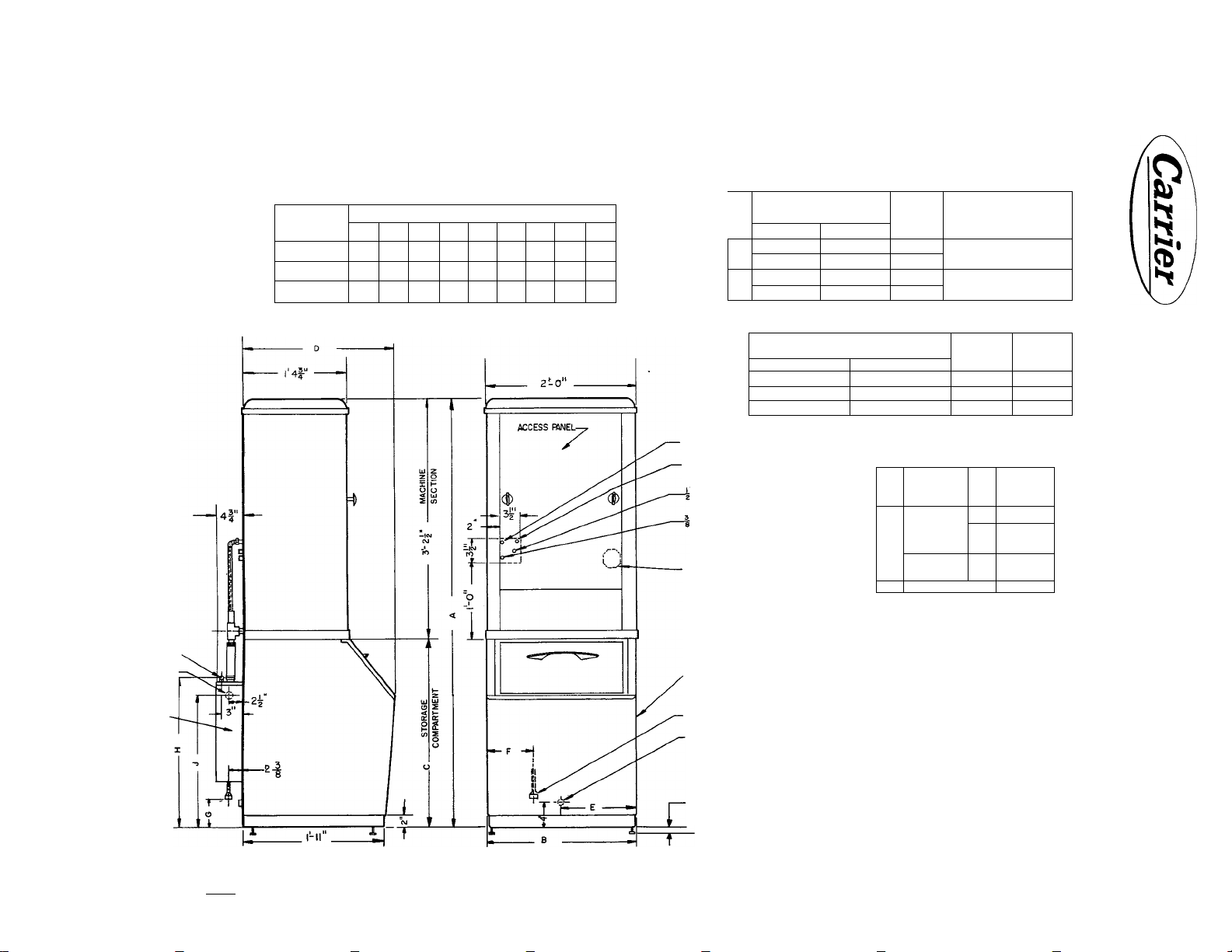
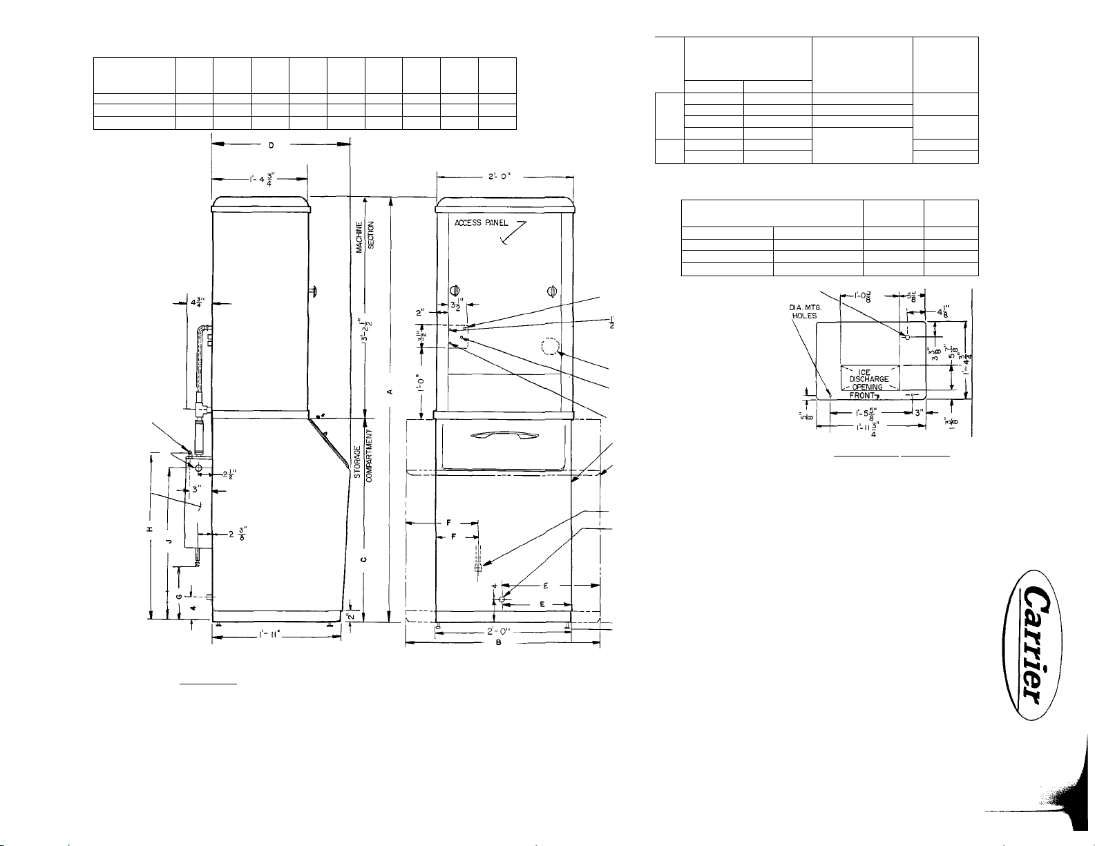
Page 7
À 1
f FSAE WLET-
INTERCHANGER.
i MPT OUTLET—
NTERCH ANGER
STORAGE
COMPARTMENT
CAPAOTYILB)
100
160
A
5 -8^ 2-0"2'-6"
2-0
240 é-4| 2-10 3'-2"
B C
3'-2" 2-1"
DIMBISION
D
ÿ-o|"!-0"
2-1 " 1- 5"
E
r-o"
F G
8i"
8i'
l'l-8
3|"
III”
III"
H
!-9"
2-0"
2-5
2'-8"
2'-8 2'-5”
PART NUMBER -
MACHINE SECTION WTH
J
MSAE INLET- CONDENSER
■INTERCHANGER TO FLOAT VALVE
CCNNECTION
MSAE OUTLET-CONDENSER
MSAE OUTLET- DRIP PAN
HEAT INTERCHANGER
NO CRUSHER
26H3- 309
£
o
a
26H3- 329
26H3- 709 26H3-7I9
i
26H3- 729
s
DOMESTIC PART NUMBER -
ICE STORAGE COMPARTMENT
SEA SPRAY GREEN FINISH'
26D3-2 49
26D5- 449A
26D5-469A
WITH CRUSHER
26H3-319
26H3-339 WHITE
26H3-739
UIM. 1*1 I «
4 HpLES
FINISH
SEA SPRAY
GREEN
SEASFW
GREEN
WHITE
WHITE FINISH
26D3^ 259 100 83
26D5- 459A 160 104
26D5- 479A
3«' DIA. THERMOSTAT BULB OPENING
ELECTRICAL
CHARACTERISTICS
ALL UNITS ARE f HP)
115- 1-60
230-1-50
STORAGE
CAPACITY
(LB)
i-of- —»
240
,1 i f
-4|"
mi®
NET
WEIGHT
(LB)
135
D
s
^ ioh-
INLET OPENING TO JUNCTION
BOX - REAR PANEL
CE STORAGE COMPARTMENT
ICE
DISCHARGE
-^OPENING ^
-5-
~T
lo|CD
MACHINE SECTION- BOTTOM VIEW
FRONT-# —!—
l‘-5f -
-l-llx"
___
V-i®
• 1
__L
Z
t/>
5
z
(/)
lyTTERCHANGER.
TRi.R.0.
CHK. DE.M APPO. E.LV
DATE n-19-58
SUPERSEDES
ISSUE OF
AUTOMATIC ICE MAKER-WATER COOLED
I* FSAE CLEANOUT - INTERCHANGER
f MPT DRAW - storage COMPARTMENT
ALLOW APPROX 2" FOR LEVELING SCREWS
KJ
DWO NO
26H3 - 423
Page 8
STORAGE
COMPARTMENT
CAPACITY
16 0
240 6-41'
500
6-4j
PART NUMBER
MACHINE SECTION WITH
HEAT INTERCHANGER
A
2- O"
2- 10“
4L5"
B
C
d
3- 2"
2-1"
3^2" 2-1“
- ÿ-o" • 2-a“
E
____
1-0"
1-5"
E__..
0-8Ì 0- Ili 2-8" 2-5"
1-1 r
G
o'-Ili"
H
- J-
¿-8" 2-ë'
N0 CRUSHER
26H5-349A 26H5-369A
ü
1—
26H5-359A
CO
26H5-389A
%
Q
26H5-399A
26H5-669A 26H5- 689A
cr
26H5-679A 26H5-699A
WITH CRUSHER
26H5-379A
26H5-409A
26H5-419A
UNITS WITHOUT CRUSHER WEIGH 301 LB. NET
WITH CRUSHER, UNITS WEIGH 341 LB. NET.
ELECTRICAL
CHARACTERISTICS
(ALL UNITS ARE ^HP)
II5-I-60
230-1-60
115-1-60
230-1-60
FINISH
SEA SPRAY
GREEN
Ï'IIITC
, WHITE
KJ
|"FSAE INLET-
INTERCHANGER.
r'MPT OUTLET-
• INTERCHANGER \
INTERCHANGER
DOMESTIC PART NUMBER
ICE STORAGE COMPARTMENT
SEA SPRAY GREEN FINISH
26D5-449A
26D5-4 69A 26D5- 479A
26H5-6 2 9B 26H5- 649B
INTERCHANGER TO FLOAT
VALVE CONNECTION
MSAE INLET-CONDENSER
INLET OPENING TO JUNCTION
BOX- REAR PANEL
X MSAE OUTLET- CONDENSER
2
1 MSAE OUTLET- DRIP PAN
8
160 LB. ICE STORAGE COMPARTMENT
240 LB. ICE STORAGE COMPARTMENT
i"FSAE CLEAN OUT-INTERCHANGER
2
1"mPT drain-STORAGE COMPARTMENT-500 LB. BIN DRAIN LOCATED ON
4
BOTTOM (L OF BIN, r'MPT- CAST BRASS
ALLOW APPROX. 2"F0R LEVEUNG SCREWS
WHITE FINISH
26D5- 459A 160
JDIA. THERMOSTAT BULB OPENING
(2)1
4
STORAGE
CAPACITY
(LB.) (LBJ
240 135
500
MACHINE SECTION-BOTTOM.VIEW
NET
WEIGHT
104
225
D
£
z
(/>
5
z
U)
DR- ERA
CHK. D.E.M
DATES- 8- 62
SUPERSEDES
ISSUE OF ir-19-sa
AUTOMATIC ICE MAKER-WATER COOLED
DWG. NO.
26H5-423
Page 9

Carrier
INSTALLATION
26H
-m
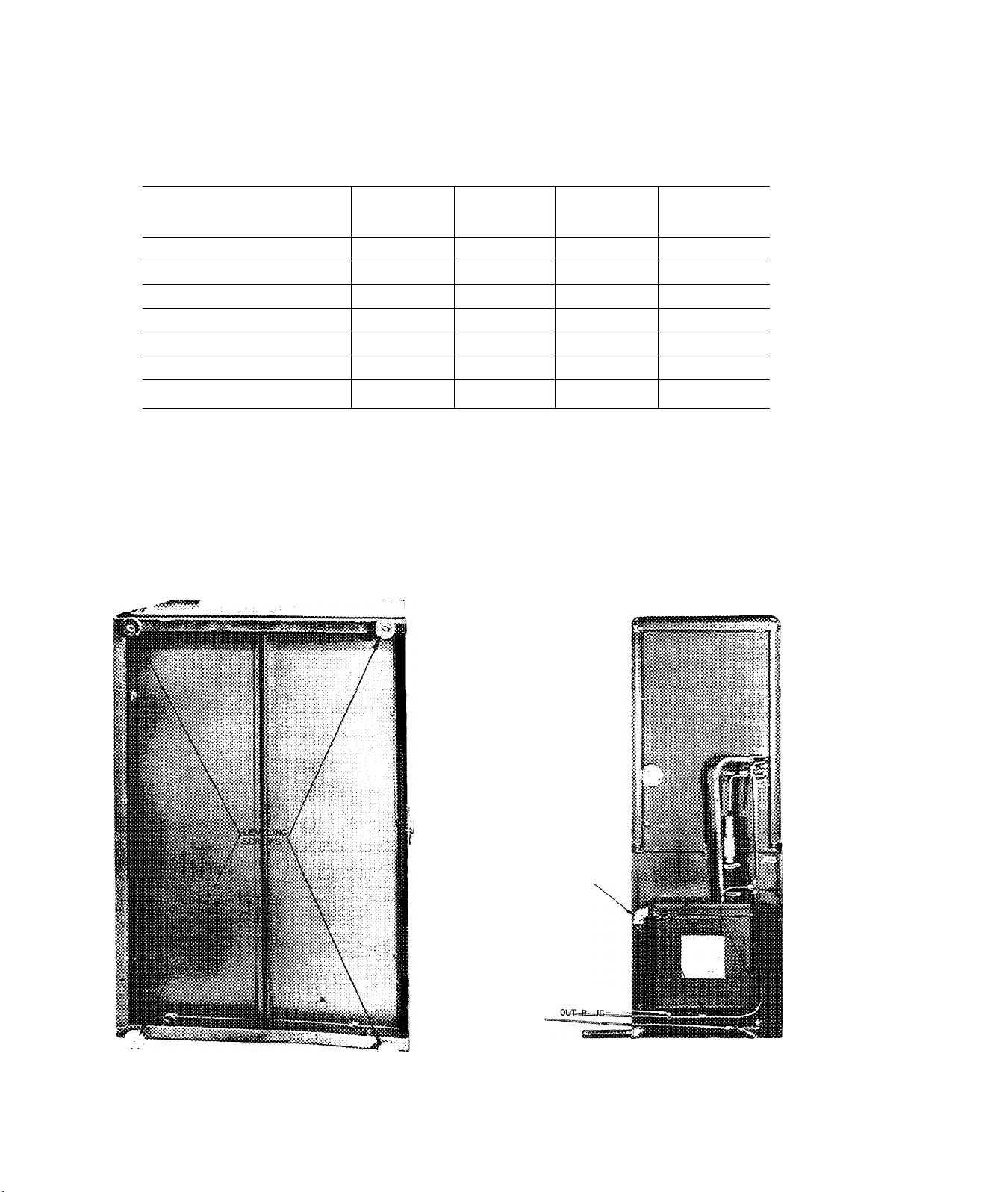
1. CHECK SHIPMENT
The unit is shipped in three cartons. One contains
the machine compartment, one the storage bin and
one the siphon interchanger assembly.
TABLE 1 - PARTS LIST
MACHINE SECTION CRATE
Model
26H3 1
26H5
Quantity
1
1
1
1
1
1
1
1
1
Description
Machine Section
Outside Standpipe
Water Strainer
Crusher Guard*
Inside Standpipe &
Rubber Grommet
Machine Section
Outside Standpipe
Water Strainer
Crusher Guard*
Inside Standpipe &
Rubber Grommet
2. SELECT PROPER LOCATION
Select a location for the unit before delivery. The
following should be considered:
1. Convenience - Select a clean dry place as
close as possible to the point of ice consump
tion. Consult the user before deciding.
2. Room Temperatures
Minimum 50 F - Room temperatures below this
may cause erratic control operation.
Maximum 100 F - Room temperatures above
this overload the compressor and reduce unit
capacity.
3. Floor Strength - See Table 2.
TABLE 2 - OPERATING WEIGHT AND
DIMENSIONS
Model No.
26H3
Total Weight
(Bin Full of Ice)
389
Bin
Cap.
100 25 X 24
Floor
Area (In.)
#
On units equipped with crusher only.
STORAGE BIN CRATE
Size, Lb. Quantity
100, 160, 240,
500 4
HEAT INTERCHANGER PACKAGE
Quantity
1
1
2 Hose Clamps
STORAGE BIN PARTITION
Quantity Description
1
1
Partition
Machine Screws
Description
Storage Bin
Leveling Screws
Description
Interchanger
Rubber Hose
26H5 565
26H5
26H5 940
NOTE: Add 40 lb for Crusher.
4. Clearance:
Top
Rear and Sides
Front
5. Water Supply - See Section 12.
6. Drain Connections - See Section 12.
7. Electrical Connections - See Section 13.
3. MOVE UNIT TO LOCATION
Move the unit to the proper location before uncra
ting. Crated dimensions are shown in Table 3.
676
10" Minimum
6" Minimum
24" Minimum
160 25 X 24
240 25 X 34
500
32 x50
26H-57PD
Page 10
26H INSTALLATION
TABLE 3 - CRATED DIMENSIONS
Carrier
Height Depth
(in.)
26H5 Machine Section
26H3 Machine Section
100 lb. Bln
160 Lb. Bin 39-1/2
240 Lb. Bin
500 Lb. Bin
Heat Interchange!
4. UNCRATE THE BIN
Uncrate the bin first since it serves as the base
for the unit.
5. INSTALL LEVELING SCREWS
Support the bin with the four leveling screws sup
plied with the bin. See Fig. 1. The top of the bin
can be used for leveling.
43-1/2
43-1/2
31-1/2
39-1/2
45-1/2
22-1/2
Width
(in.)
23-1/2
23-1/2
27
26-1/2
26-1/2
34-7/8 49-1/2
17
6. UNPACK AND MOUNT THE HEAT
Remove the interchanger and parts from the carton.
Mount the heat interchanger on the back of the bin
with the 6 sheet metal screws in the paper envelope.
The position of the interchanger on the back of the
bin is shown in Fig. 2.
(in.)
28-1/2
28-1/2 236
26
25 112
35
5 18
INTERCHANGER
Weight
(lb.)
307
95
142
225
t
FIG. 1 - LEVELING SCREWS INSTALLED
26H-57PD
10
HEAT INTERCHANGER
DRAIN
HEAT INTERCHANGER
CLEAN
FIG. 2 - POSITION OF HEAT INTERCHANGER
ON THE BIN
Page 11
Carrier
INSTALLATION
26H
7. MOVE THE BIN TO APPROXIMATE LOCATION
Move the bin as close as possible to the final lo
cation before placing the machine section on top
of it.
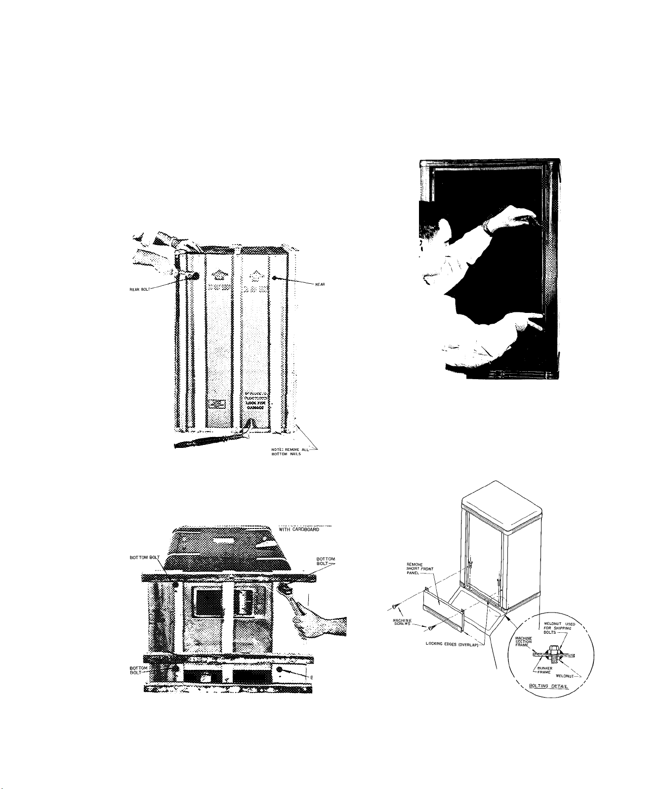
8. UNCRATE THE MACHINE SECTION
Uncrate the machine section as shown in Figs. 3
and 4.
9. REMOVE THE FRONT TOP, AND SIDE PANELS
Remove the front, top, and side panels in that order
before moving the machine section.
FIG. 5 - REMOVING SCREWS HOLDING TOP
AND SIDE PANELS
m
FIG. 3 - UNCRATING - REAR BOLTS
FIG. 4 ■ UNCRATING - BOTTOM BOLTS
10. PLACE MACHINE SECTION ON TOP OF BIN AND BOLT IN POSITION
Remove the short front panel. Using the two cap
screws in the cloth bag shipped with the bin, bolt
the machine section in place as shown in Fig. 6.
BOTTOM BOLT
FIG. 6 - BOLTING MACHINE SECTION TO BIN
II
26H-57PD
Page 12
INSTALLATION
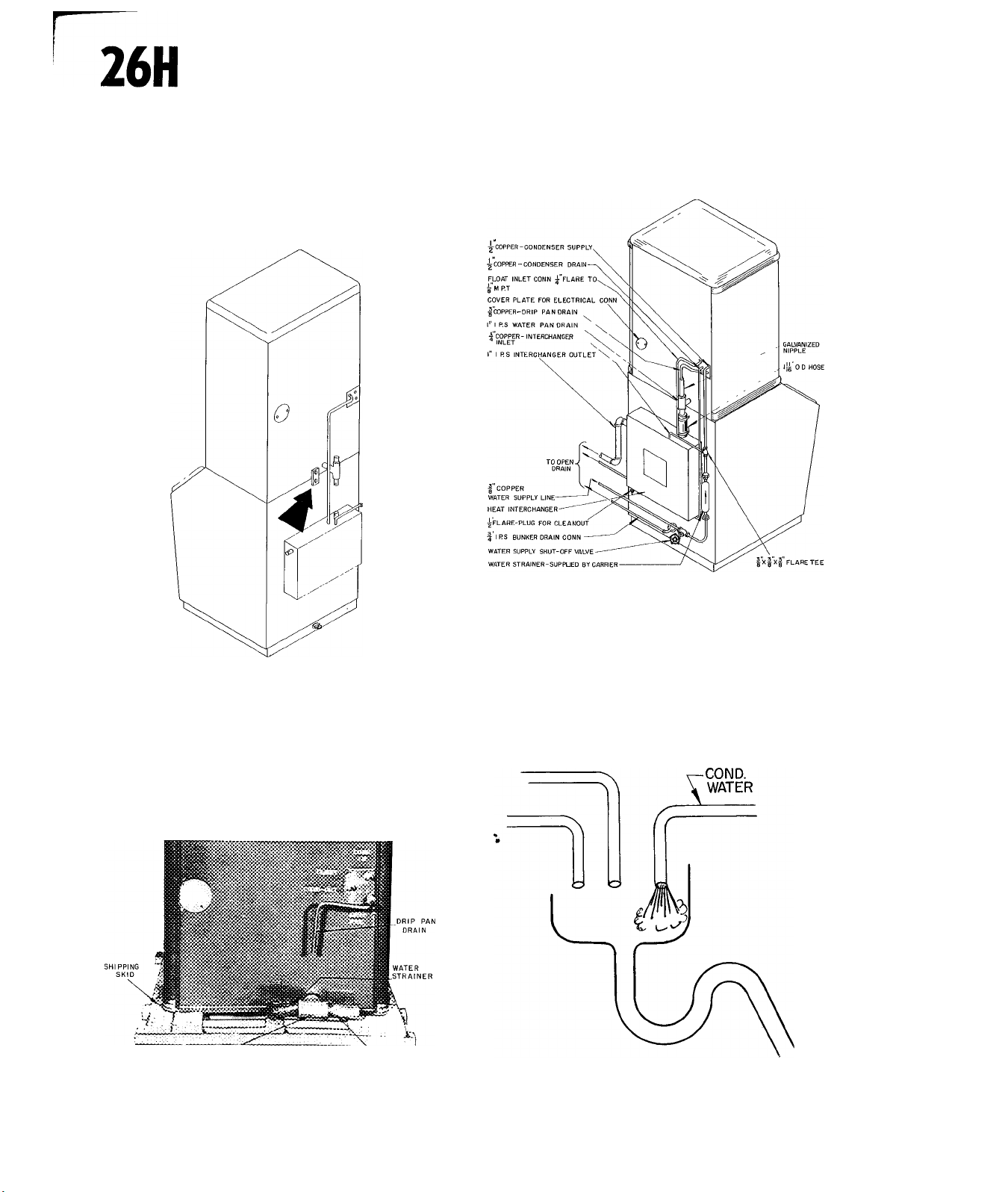
n. BOLT TIE BAR AT REAR OF UNIT
Lock the two sections together with the tie bar
shipped on the back of the machine section. See
Fig. 7.
Carrier
^1^
Refer to Fig. 9 for recommended piping details.
FIG. 7 - BOLTING TIE BAR AT REAR OF UNIT
12. INSTALL WATER SUPPLY AND DRAINS
Fig. 8 shows the piping connections and parts sup
plied by the factory. Any approved source of drink
ing water can be used provided a 30-60 lb. water
pressure can be maintained. If the pressure ex
ceeds 60 lbs. a pressure reducing valve must be
used.
FIG. 9 - PIPING DIAGRAM
The drain lines should be piped separately to an
open drain. The bin drain must be pitched down
ward for gravity flow. See Fig. 10.
r 6ALVAN12ED"T
FIG. 8 - PARTS SHIPPED ON BACK OF
MACHINE SECTION
26H-57PD
GALVANIZED NIPPLE
f
FIG. 10- OPEN DRAIN
12
Page 13

Carrier
INSTALLATION
26H
m
13. MAKE ELECTRICAL CONNECTIONS
Obtain a voltmeter or the special portable line vol
tage tester recommended in the Carrier Product
Information Book. For satisfactory results, the vol
tage when the unit is running must always remain
within 10 percent of the rated nameplate voltage.
Check the current supply at the customer's prem
ises and resolve any wiring problems before pro
ceeding with the installation. See Table 4 for nec
essary electrical data.
TABLE 4
FULL LOAD
MODEL VOLTAGE
26H3
26 H5
26H5
Carrier
Part No.
115
115
230 6.7
General
Electric
Part No.
CURRENT
10.8 15
13.4 17 1/2
TABLE 5 - 208V APPLICATION
Total
Amps
Allowable
208V APPLICATION "BUCK AND BOOST"
TRANSFORMER
For application on 208 volt circuits, a transformer
is recommended to boost the voltage from 208 volts
to 230 volts. The information in Table 5 should be
helpful in selecting the transformers. It is selected
on the basis of making a 10% voltage boost from
205 volts to 225 volts.
FUSETRON
SIZE
9
WIRE SIZE (AWG) TYPE R,T
LENGTH OF RUN
25'
14
12 12
14
50'
12
14
100'
10 6
8 6
14 12
200'
m
HT04AH026
HT04AH035
Not stocked
at Carrier
The wiring connections for this transformer for a 10% voltage boost are as follows:
9T51Y6171 12.5 amps.
9T91Y6172
-INPUT-
FIG. n - "BUCK AMD BOOST" TRANSFORMER WIRING
25 amps. Four units without crushers or two units with
37.5 amps.
-OUTPUT-
-—I 2
Two units without crushers or one unit with
crusher plus one without crusher.
Will NOT handle two units with crushers.
crushers plus two units without crushers.
Will NOT handle four units with crusher.
Six units without crushers or three units with
crushers plus three units without crushers
13
26H 57PD
Page 14
26H INSTALLATION
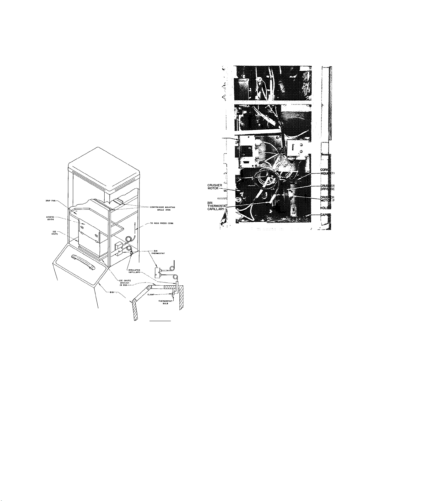
14. INSTALL BIN THERMOSTAT BULB
Remove the tope holding the bin thermostat cap
illary and bulb in a coiled position inside the right
side of the machine section. Uncoil 4 or 5 loops
of the capillary and insert the bulb through the hole
in the right rear corner of the machine section into
the bin. Run the capillary along the top of the bin
and down the back of the thermostat bulb bracket.
See Figs. 12 and 13.
BIN
THERMOST^r
a HI PRESS.
CUTOUT
Carrier
OR BIN
tmsSostat
ARY
SIDE View DETAIL
FIG. 12 - BIN THERMOSTAT CAPILLARY AND
BULB ARRANGEMENT
26H 5-500. 240 AND 160 LB. BINS
Attach the clamp to the bottom hole in the bracket;
insert the thermostat bulb in the clamp so it ex
tends 1/2" below the bottom of the bracket. Tighten
the clamp.
26H3-100 LB. BINS
FIG. 13
RIGHT SIDE OF 26H3 SECTION -
PANELS REMOVED
Instructions for mounting the thermostat capillary
and bulb on a partition are included in the partition
package.
CAUTION: Insulate the capillary where it goes
through the hole in the machine section and the
bin with tape or rubber tubing.
15. INSTALL CRUSHER GUARD
Remove crusher guard assembly from ice chute on
grusher models and install per instructions in para
graph 19 on page 39.
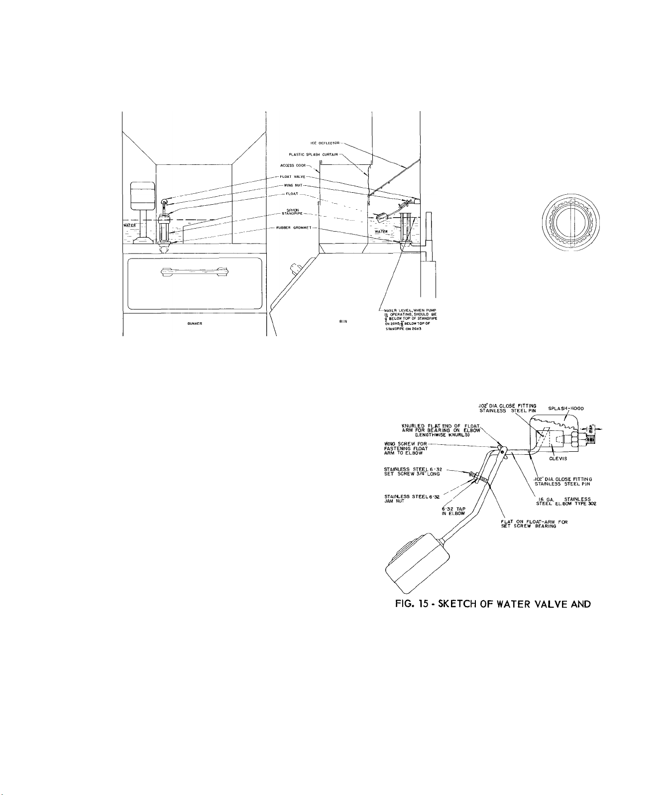
16. INSTALL SIPHON STANDPIPE AND ADJUST FLOAT
Remove the ice deflector to gain access to the water
pan. Fig. 14.
With the clamp attached to the bracket at the top
hole in the arm of the bracket, insert the thermo
stat bulb in the clamp so the clamp is approximately
in the middle of the bulb and tighten the clamp.
26H-57PD
Place standpipe assembly and rubber grommet in
water pan drain. (See Fig. 14). On 26H3 unit,
remove knockout in stainless steel jacket. (Do
not remove on 26H5 unit.)
14
t
Page 15
Carrier
INSTALLATION
26H
FIG. 14 - CORRECT WATER LEVEL
Turn on the water and set the float valve to main
tain a water level 3/8 " below the top of the siphon
stcujdpipe for the 26H3 and 1/2" below for the 26H5.
See Fig. 14.
The water level should be set with the pump off,
and checked again with the pump running, after the
water level has settled. To check the Siphon action
let the unit run on "Pump" until the float shuts ofi
the water to the pan. Turn the selector switch to
"Off". The water in the header and the water pipes
will drop down and raise the water pan level until
the Siphon action begins and the water pan is si
phoned out.
If the water pan fails to siphon out, the water level
has been set too low. If the water siphons or over
flows the inner standpipe when the pump is running,
the water level has been set too high.
FLOAT ASSEMBLY
17. REPLACE THE ICE DEFLECTOR
After the float is set, tighten the wing nut on the
float arm and the setscrew to the flat on the float
arm. See Fig. 15.
The bottom of the deflector sets in two clips fas
tened to the inside front wall of the water pan. The
back of the ice deflector rests against the front of
the evaporator shroud. See Fig. 14.
15
26H-57PD
Page 16
26H
INSTALLATION
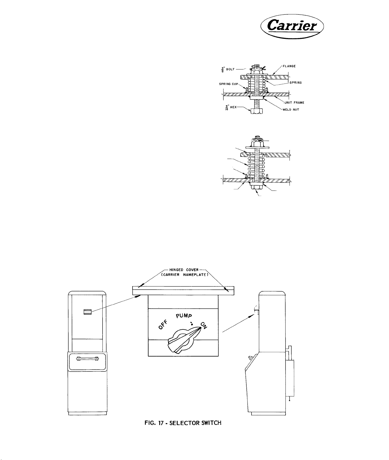
18. LOOSEN COMPRESSOR HOLD-DOWN BOLTS
26H5
Loosen the four compressor hold-down bolts. See
Fig. 16. Check to see that the compressor is float
ing freely on its mounting springs.
When the machine is to be moved, retighten the hold
down bolts to prevent damage.
26H3
The 26H3 is spring mounted internally. Do not
loosen compressor hold-down bolts.
19. START THE UNIT
Shutoff valves are backseated and the unit is ready
for operation when shipped.
Turn the selector switch located under the hinged
nameplate to the "ON "position and check the opera
tion. See Fig. 17.
If the unit fails to start^ push the reset button on
the Safety Overflow Switch.
NOTE: The 26H5 unit may cycle several times on
the high pressure cutout during initial start
up or after a prolonged shut-down. While
such cycling is perfectly normal, it may
COMPRESSOR
SHIPPING POSITION
DO NOT REMOVE
COMPRESSOR
FLANGE
SPRING
SPRING CUP
UNIT FRAME
OPERATING POSITION
COTTER PIN
WELD NUT
BOLT TIGHT AGAINST
WELD NUT
FIG. 16 - COMPRESSOR HOLD-DOWN BOLTS
be reduced by shutting off the unit for about
a half a minute then starting again.
The 26H3 may cycle on overload several
times upon attempting to start after a pro
longed shutdown.
26H-57PD
16
Page 17

Carrier
INSTALLATION
26H
nr
20. CHECK OPERATION
The operation should be as follows:
(a) Freezing for 30 or 40 minutes - compressor
operating, pump operating and hot gas so
lenoid closed. A longer freezing period may
occur where the water supply temperature is
high.
(b) Defrosting for approximately 6 minutes - com
pressor operating, hot gas solenoid open and
water pump off.
(c) Overrun - Time, which is the time between the
falling of the last cube and the start of the
next freezing cycle, should be about 1/2 a
minute to 1-1/2 minutes, to increase overrun
time, raise the setting of the righthand ele
ment (cut in) of the Main Control Thermostat.
(d) The hole in the average ice cube should be
about 3/16" diameter. Run two or three batch
es, since the first harvest will produce-cubes
with larger than overage holes.
21. FINAL CHECK LIST
3. Has the overrun time (par 20C) been set?
4. Have all the controls been checked?
5. Has the voltage been load tested and checked
against nameplate voltage?
6. Have the compressor hold-down bolts been loos
ened so that the compressor rides freely on its
mounting springs?
7. Has the float been set so water will siphon out
at the end of each freezing cycle?
8. Operate the unit for at least two or three cycles.
Is it operating properly?
9. Is the unit quiet?
10. Is the unit clean?
11. Have the installation and warranty cards been
filled out?
1. Is the unit level?
2. Have all electrical and piping connections been
made?
12. Has the owner been given the Operating Instruc
tion booklet and has he been instructed on how
to operate the machine?
17
26H-57PD
Page 18

Carrier
#
Page 19

^-rar
Carrier
1. HOW THE AUTOMATIC ICE MAKER WORKS
The Ice Cube Maker is fully automatic and operates in two alternate cycles - first the freezing cycle, then the
harvesting cycle. The compressor operates continuously during both cycles
SERVICE
26H
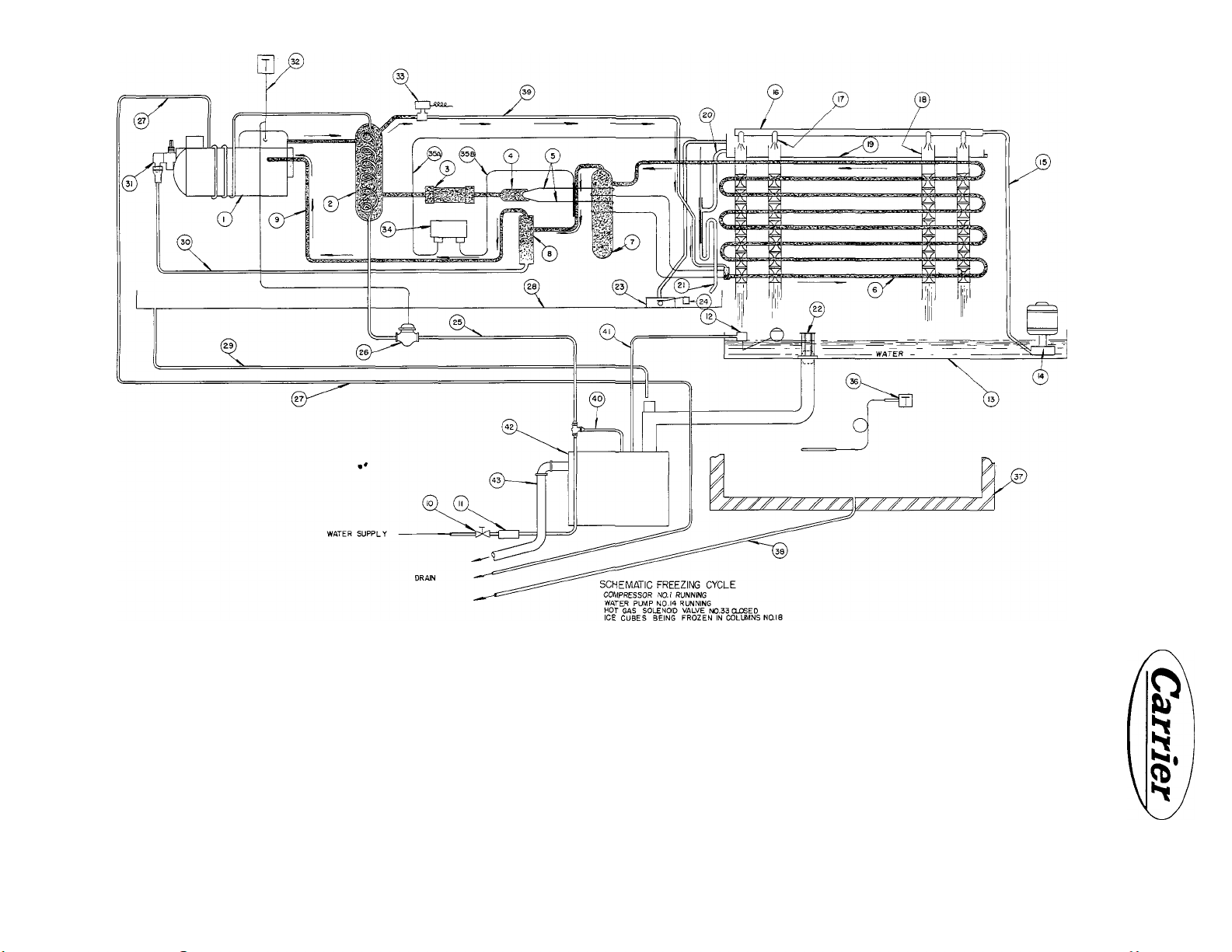
FREEZING CYCLE (SEE FIG. 1)
During the freezing cycle water is pumped from the
water pan (13) to a water header (16) at the top of
the unit. From, the water header it flows over individ
ual spreader plates, down the four inside surfaces
of each of the square, stainless steel freezing col
umns (18). Here water is frozen into individual
cubes. This is accomplished by unique evaporator
design. Copper sleeves are bonded to the outside
of each stainless steel column at eight points
spaced along its vertical dimension. Sections of
the evaporator coils are in turn soldered to these
copper bands. Because of the high rate of heat
transfer through the copper and the low conductiv
ity of the stainless steel, individual cubes start
to form inside the columns opposite each copper
band and grow from this point. The hole in the cen
ter is due to continuous water flow - necessary to
form clear cubes.
DEFROST CYCLE (SEE FIG. 2)
When the passage through any one of the columns
becomes restricted because of ice formation, water
backs into the overflow trough, (19), and drops into
the thermostat well,. (21). Here the cold water acti
vates the cut-out side of the Ranco two-bulb con
trol, (35A). This starts the harvest cycle by stop
ping the water pump (14), and opening the hot gas
solenoid valve, (33). The solenoid valve allows hot
gas to pass directly from the condenser, (2), to the
evaporator coil, (6). The cubes are melted loose
and allowed to drop through the ice chute into the
storage compartment, or bin, (37). If the cubes fail
to drop, the water will continue to build up in the
overflow trough and will flow into the safety over
flow well'(23). This actuates a safety switch (24)
and shuts the machine off.
The hot gas passing from the evaporator coil through
the suction line, warms the capillary bulb (35B)
attached to the vertical portion of the suction line
leading from the first accumulator. The warming of
this_ bulb activates the cut-in side of the Ranco
two-bulb control, which starts the machine on the
freezing cycle. As soon as the Ranco control moves
the machine into the freezing cycle, the water pump
is automatically started and the solenoid valve
closes.
19
26H-57PD
Page 20
KJ
<
1- COMPRESSOR
2- CONDENSER
3- STRAINER a DRYER
4- ADAPTER (FOR TWIN CAPILLARIES)
5- TWIN CAPLLARIES
6- EVAPORATOR COILS
7- 1ST ACCUMULATOR
8- 2ND ACCUMULATOR
9'SXTION LINE
10- SHUT-OFF VALVE (WATER SUPPLY)
11- WATER STRAINER
FUDAT VALVE
WATER PAN
WATER PUMP
WATER LINE (TWIN)TO WATER HEADER
WATER HEADER
WAT^R NOZZLES
FREEZING COLUMNS
OVERFLOW TROUGH
DRAIN LINE FROM OVERFLOW TROUGH
THERMOSTAT WELL
•SIPHON STANDPIPE (WATER PAN DRAIN)
FIG. 1 - SCHEMATIC FREEZING CYCLE
23- SAFETY OVERFLOW WELL
24- OVERFLOW SAFETY SWITCH
2 5-WATER SUPPLY TO. CONDENSER
26- WATER REGULATING VALVE
27- CONDENSER WATER DRAIN
28- DRIP PAN FOR MACHINE SECTION
29- DRIP PAN DRAIN LINE
30- OIL RETURN LINE
31 • SERVICE SHUT-OFF VALVE
32-HIGH PRESSURE CUT-OUT
33 HOT GAS SOLENOID VALVE
*
34- MAIN CONTROL THERMOSTAT
35A- MAIN CONTROL “CUT-OUT C^ILLARY
35B-MAIN CONTROL'CUT-
36 - BIN THERMOSTAT
37 - BIN
38 - BIN DRAIN
39 - HOT GAS LINE
40 - WATER SUPPLY TO HEAT INTERCHANGER
41- WATER SUPPLY TO SUMP
42- HEAT INTERCHANGER
43- HEAT INTERCHANGER DRAIN
IN" CAPILLARY
1
Page 21

~W
Carrier
SERVICE
26H
t?T
sssssss?;?;
i
ii iSi
gSesni-
II
m
_i
U
>U
I—
CO
O
Di
O
y
H
<
s
LU
X
I
CN
o
tl.
21
26H-57PD
Page 22

26H SERVICE
Carrier
FIG. 3 - ICE CRUSHER ASSEMBLED - FRONT VIEW
CRUSHER OPERATION
The defrost and freezing cycles of an Ice Maker
with a crusher are identical to those of units without
a crusher. Normally the crusher is a factory mount
ed accessory, enclosed in the machine section. If
desired, a crusher package may be purchased sep
arately for installation. (See Fig. 3)
CAUTION; When cleaning units equipped with
crushers or performing service operations, discon
nect the power supply.
The two crusher control knobs are mounted on the
lower front panel (Fig. 4). When the knob on the
left is positioned on "Crushed" the cubes pass
through the crusher and crushed ice falls into the
bin. Fineness of the crushed ice is controlled by
the knob on the right. When the knob on the left
is positioned on "Cubes", the ice cubes bypass
the crusher and fall into the bin.
The knob marked "Crushed - Cubes" controls a
switch to the crusher motor and the position of a
damper to direct the cubes. The motor is cut out of
the control circuit when the switch is turned to
"Cubes".
is in the "Crushed" position and the bin thermostat
stops the unit during the harvest cycle^ the crusher
me tor will continue to operate until the main control
switches to the freezing position or the selector
switch is turned to "Pump" or "Off". This prevents
accumulation of cubes at the crusher entrance.
#
When ice builds up in the bin and touches the ther
mostat bulb, the unit will stop. If the crusher knob
26H-57PD
FIG. 4 - ICE CRUSHER CONTROLS
22
Page 23

Carrier
SERVICE
26H
~w
REMOVING THE PANELS
To remove the top front panel turn both handles so
they are horizontal and lift it out. To remove the
top panel remove the screws shown in Fig. 5. Tilt
the panel up and back to disengage it from the back
panel. The side panels are held in place at the
front by two screws and the bottom front panel. The
side panels engage with the flanged edge of the
back panel. Do not remove the back panel except
when absolutely necessary. It is held in place by
six screws threaded into the frame.
Cleaning and inspecting can be done by removing
the front access door, splash curtain, and ice de
flector screen. The plastic curtain is riveted to a
cross arm held in place by two screws (Fig. 6).
After inspection and cleaning, be sure to reposition
the plastic curtain properly to prevent water from
splashing into the bin. (Fig. 7).
#
FIG. 5 - REMOVING SCREWS HOLDING TOP
AND SIDE PANELS
2. REFRIGERANT CIRCUIT
L SHUTOFF VALVES
Fig. 8 is a cross sectional view of a shutoff valve
in mid-position. When the unit is shipped all valves
are backseated and should be left so during normal
operation. A brass cap and gasket cover the valve
stem to prevent leaks. The gauge ports are plugged
with two 1/8" MPT plugs.
ACCESS DOOR ICE CRUSHER CRUSHER
FIG. 6 - REMOVING ACCESS DOOR AND
ICE DEFLECTOR
26H3
There are two shutoff valves in the circuit - a suc
tion valve and a discharge valve. (See Fig. 9).
26 H5
There are three shutoff valves in the circuit - a suc
tion valve, discharge valve, and oil return valve.
(See Fig. 10).
MOTOR
23
26H-57PD
Page 24

26H
SERVICE
DISCHARGE ?
SHl/T OFF VA;,'/«
FIG. 7 - FREEZING COLUMNS. ICE DEFLECTOR, SPLASH CURTAIN,
SIPHON STANDPIPE. ACCESS DOOR AND WATER PAN ARRANGEMENT
CONNECTION TO
FIG. 8 - SHUTOFF VALVE
CILRETL«»;
SHOT 0*"'
VALVE,
GAUGE CONNECTION
FIG. 9 - TOP VIEW OF 26H3 MACHINE SECTION
26H-57PD
FIG. 10 - TOP VIEW OF 26H5 MACHINE SECTION
24
Page 25

Carrier
SERVICE
26H
Hf
2. INSTALLING GAUGES
a. Backseat suction and discharge shutoff valves.
SUCTION LINE
PRESSURE GAUGE
DISCHARGE LINE
PRESSURE GAUGE-
CHARGING HOSE ATTACHED TO THE SUCTION
VALVE WITH A 1/4" HALF UNION COUPLING
b. Remove gauge plugs and install 1/8" MPT
X 1/4" flare half union coupling.
c. Attach 1/4" OD copper gauge line, flared at
both ends, to the couplings.
d. Attach suction and discharge gauges to these
lines, leaving connection slightly loose.
e. Crack the valve off back seat, allow a small
amount of refrigerant to escape, and tighten
the flare nut.
To read line pressures, turn the shutoff valves
slightly from the backseat position. If the gauge
needle vibrates, backseat the valve until there is
no vibration but the gauge still reads line pressure.
NOTE: To conserve refrigerant, use short lengths
"FREON-12 DRUM
of small bore tubing when installing gauges. This
unit is sensitive to charge and repeated installa
tion and removal of gauges with necessary purging
vl
of air will result in an undercharge of refrigerant.
FIG. 11 - CHARGING MANIFOLD ATTACHED
FOR CHARGING UNIT
3. PUMP DOWN OF COMPRESSOR
If the refrigeration system must be opened at the
compressor, first "Pump Down". Proceed as follows:
1. Install a pressure gauge to the suction shut
off valve.
2. Front seat the suction shutoff valve.
3. Front seat the oil return line shutoff valve
(on 26H5).
4. Operate the compressor intermittently until
the suction pressure gauge indicates 0 to 2
PSIG pressure is being maintained in the
crankcase.
5. With the compressor stopped, front seat the
discharge shutoff valve.
6. Loosen the discharge shutoff valve gauge
plug slightly and bleed off any remaining pres
sure. The compressor can then be opened or
removed.
7. After repairing the compressor, evacuate and
purge it to remove residual air. Remove the
pipe plug from the gauge connection of the
discharge shutoff valve. Operate the com
pressor for about 10 minutes. Place your thumb
over the discharge valve gauge connection^ at
the some time stopping the compressor. Crack
open the SUCTION shutoff valve, momentarily,
allowing a small amount of gas to enter the
compressor. Front seat the suction shutoff
valve immediately. A slight gas pressure
should not be felt against your thumb. Re
place the pipe plug. The suction, discharge
and oil return line shutoff valves can now be
backseated and the machine is ready for op
eration.
25
26H-57PD
Page 26

26H
4. CHARGING WITH REFRIGERANT
SERVICE
TABLE 1 - REFRIGERANT CHARGE (R12)
Carrier
MODEL
26H5
26H3 9 " condenser and 9 " accum. 1 lb. 11 oz.
26H3 Serial No. 331784 Change to 18"cond.-
26H3
26H3 Serial No. 510446 change to 15"cond.—
If the unit is undercharged, back seat the suction
shutoff valve. Remove a gauge port plug from the
valve; connect a charging line from a drum of re
frigerant 12. Tighten this line at the drum, but make
a loose connection at the suction shutoff valve.
Crack the valve on the drum so that refrigerant va
por will force air from the charging line out the
loose connection. After purging the air from the
charging line, tighten the connection at the suc
tion shut-off valve. Open the suction valve to a
point midway between the back-seated and frontseated positions. With the suction shutoff valve in
this position, it is possible to read the system pres
sure during the charging period. The refrigerant 12
drum should be in an upright position to admit va
por only.
No changes
9 " accumulator
Serial No. 411152 change to 15"cond.9 " accumulator
10 1/2" accumulator 2 lb. 9 oz.
IDENTIFICATION
CHARGE
3 lb. 8 oz.
2 lb. 3 oz.
2 lb. 3 oz.
WEIGHING IN CHARGE
The most accurate method of charging a refrigerant
system is weighing in the charge. Proceed as fol
lows:
1. Bleed any charge remaining in the system,
then start the compressor and pump out the
system through the discharge valve.
2. With the compressor still running, connect the
drum of refrigerant to the suction valve.
3. Back seat the discharge valve and immediately
turn off the compressor.
4. Weigh the drum of refrigerant (it is easier to
weigh a charge if the weight of the drum can
*, be checked during the charging process).
i
If the unit is overcharged, turn the unit off. Back
seat the discharge shutoff valve. Attach a charg
ing line to one of the gauge ports in the valve and
attach a charging manifold to the other end of the
charging line. Turn the shutoff valve to the middle
position; start the unit. Bleed refrigerant from the
charging manifold in 5-second intervals until the
charge is correct. Turn the unit off. Back seat the
shutoff valve and remove the charging line. Replace
the gauge port plug and start the unit.
26H-57PD
5. Open the suction valve and crack the valve
on the drum of refrigerant. Start the compressor.
6. Continue to charge until the scale shows the
proper amount of refrigerant has been fed into
the system.
7. Close the valve on the drum and then the suc
tion shutoff valve.
8. Disconnect the charging line.
9. Leak test the system.
26
t
Page 27

Carrier
SERVICE
26H
W
i
FROST LINE METHOD OF CHARGING
By establishing a frost point on the suction line,
it is possible to charge these units to within one
ounce of their specified charge. By this, frost point,
it is also possible to determine whether or not a
machine is only partially charged. Below are listed
the recommended methods for charging the H3 and
H5 ice makers, which require a partial or a full
charge. Frostline should be at the point indicated
when the machine has operated on the freezing
cycle for 20 minutes.
CAUTION: If Freon is added in small amounts, the
frost line will continue to move towards the small
accumulator. If Freon is added too rapidly, the
frost line will disappear. It is then necessary to
wait until the frost reappears before adding or
bleeding off refrigerant.
After making sure that the machine is leak free
and in good running condition, proceed as follows
with the pump runnfng during the entire freezing
cycle.
Method lA - 26H3 Ice Maker No Charge in Unit
2. Charge slowly until the suction shutoff valve
and flare nut frost
3. Bleed off gas until frost just recedes from valve.
Method 2A - 26H5 Ice Maker No Charge in Unit
1. Remove first clip immediately above small ac
cumulator, and pull back two or three inches of
the suction line insulation.
2. Start machine with pump on. Charge until suc
tion pressure is 15 PSIG.
3. Discontinue charging and allow machine to run
for 10 minutes. During this period, check to
see if the suction pressure is holding at ap
proximately 15 pounds.
4. Charge slowly until ffost forms on the suction
line between the small accumulator and the
suction shutoff valve on the compressor.
5. Bleed off gas until frost line recedes back to
the joint on the top of the second accumulator.
6. Allow machine to run through two complete cy
cles to check operating pressures.
1. Start the unit with the pump running. Charge
until the suction pressure is 15 PSIG.
2. Continue running the machine for 10 minutes
without adding to the charge.
3. Add gas slowly until frost forms on the suction
shutoff valve and the flare nut.
4. Bleed off slowly until frost just recedes from
valve.
Method IB - 26H3 Ice Maker Partial Charge in Unit
1. Start unit and let it run undisturbed for 20 min
utes.
Method 2B • 26H5 Ice Maker Partial Charge In Unit
1. Remove insulation from suction line 2 or 3"
above second accumulator.
2. Start machine and allow it to run for 20 min
utes undisturbed.
3. Charge slowly until frost forms on fhe suction
line between the small accumulator and the
suction shutoff valve.
4. Bleed off gas unfil frost line recedes back to
the top of the second accumulator.
5. Allow machine to make two complete cycles to
check its operating pressures.
27 26H-57PD
Page 28

26H SERVICE
Carrier
5. OPERATING PRESSURES
Table 2 shows suction and head pressures during
a normal freezing and defrost cycle.
6. COMPRESSOR
OIL CHARGE 26H3
The oil charge is 45 oz. Because of this large
volume, the oil charge is not critical. The com
TABLE 2 - 26H ICE MAKER OPERATING PRESSURES (PSIG)
OPERATING PRESSURES
90
TIME INTO
CYCLE
(MINUTES)
2 129 21
4
6 134
° AIR-90° WATER
26H3 *
Head Suction
131 20 134
Head
21
26H3 +
Suction
131
134 23 159
Head Suction Head Suction
24 144
23 150
pressor is a welded hermetic and there are no pro visions for checking or adding oil in the field.
OIL CHARGE 26H5
The compressor is factory charged with two pints
of Carrier PP45EB-302 oil which is a special low
temperature refrigerant duty oil. Do not use ordinary
motof oil. Before checking the oil level, operate
the unit for at least 30 minutes to balance the oil
distribution in the system.
90°
AIR - 70° WATER
26H5 26H3 * 26H3 +
Suction Head Suction
Head
29
29 131 19 132
26 131 18 131
130
20 132 24 132 27
22
21
26H5
134
134 22
23
8 134 20 132 22 149
F
R
10 133
E
15
tj
20 130
z
25
E
30 134
35
40 129 15
45
D
E
F
R
0
S
T
26H3 From Serial No. 331784 to 510446
26H3 From Serial No. 510446 to present.
130 18 130 19 130
132
130 15
129 14
2 115
122 57 103 48
4
6
20 131
17
16
16 131 16
52 79
129
129 16 128 17 132 16 131 15
131 15 128
130
128
24 132 17 131 20 130 20
21 130
17
15 128 15 129 14
130 18 130 16 131 16 130
128 16 132
22 131
19
15
131 17 130 17 127
130
17 130
15
15
•
15
34 55 30 124
70 36 128
100 58 106 44 100
55 77
62
19 129
131
132 15 131 16
133 14 131 15
132 14
96
30
38
65 33
80
20
18
17
16
41
57
¿6H-57PD
28
Page 29

Carrier
To check the oil level:
a. Install gauges and pump down the compressor.
b. Remove one of the oil fill plugs on the side
of the compressor.
c. The oil level should be 1-1/4" as shown in
Fig. 12. Oil can be added through the oil filler
plugs. Reinstall the filler plug immediately to
prevent absorption of moisture. It may damage
the motor windings.
Caution: Avoid overcharging as excess oil may
restrict the capillaries and reduce unit capacity.
On those compressors with a sight glass, oil level
should be between 1/2 and 2/3 above bottom of glass.
SERVICE
26H
TESTING THE COMPRESSOR MOTOR
Series Test Light and Hermetic Test Cord
Fig. 13 shows atest cord that is useful as a 110/220
volt test light or as a cord for starting the com
pressor without using the unit controls. When used
as a series test light, turn screw base outlet into
the lamp socket, plug into a power source and use
insulated leads indicated in Fig. 13 as probes to
determine continuity. When used as a compressor
starting cord, the fuse is used in the lamp socket.
To start compressor using test cord, disconnect
all leads from compressor terminals. Clip common
and running leads of cord to "C" and "R" terminals
respectively. Plug cord into source of power, and
NOTE MEASURE OIL LEVEL AT 45®ANGLE AS SHOWN FROM OUTSIDE
FACE OF OIL FILL HOLE. OIL GUAGE CONSISTS OF A l/4"COPPER
TEE SOLDERED TO A STRAIGHT PIECE OF 1/4"COPPER TUBING
FIG. 12 - COMPRESSOR OIL LEVEL
momentarily touch starting lead of cord to "S" on
compressor terminals. Do not leave this prong in
contact with terminal "S" for more than one or two
seconds; otherwise the starting winding will be
damaged.
Caution: When using test cord on compressor, stand
clear of terminals. If current should arc or terminal
break, terminal may blow out with considerable
force. An arc might also ignite oil entrained in es
caping gas.
NOTE: SINGLE CAPACITORS USED FOR II5V. DUTY AND
230 V DUTY ARE DIFFERENT AS NOTED ABOVE
FIG. 13 - TEST CORD DIAGRAM
29
26H-57PD
Page 30

26H SERVICE
Carrier
Portable Line Voltage Tester
APPLICATION AND OPERATION - A portable line
voltage tester with built-in phantom load which
provides a simple means of checking single phase
or direct current circuits is shown in Fig. 14. By
reading the voltage at no load and the voltage with
phantom load it can be determined if the circuit is
adequate for starting and operating the unit. The
tester is made to Carrier specifications and includes
a table for use with ice cube makers.
PHYSICAL DATA
Case Size
Voltmeter Scale
Ampere Load
Voltage
F requency
Approx. Weight
J. & W. Company 290 Roycroft Blvd., Buffalo 21, N.Y.
8"x 8"x 4"
0-150 volts (Double Reading for
230V)
11.5
115 - 230
25, 50, 60 cycles or direct current
5 pounds
Order Directly from
the suction line with a 1/2" plug to prevent
moisture from entering the system.
2. Cut the discharge line and sweat in a 1/4"
SAE male copper to flare connection. Cap this
connection to prevent moisture from entering
the system.
3. Disconnect the compressor leads at the se
lector switch and thermostat.
4. Remove the four compressor mounting bolts
and lift the compressor from the unit.
5. Seal all openings on the compressor to pre
vent moisture from entering prior to repair or
exchange.
6. If compressor failed due to motor burnout, see
"Replacement After Motor Burnout".
7. Install the replacement compressor. The re-
placemsat compressor is shipped with the dis
charge line fastened to the suction shutoff
valve gauge portby means of a 1/4" flare nut.
8. After completing all wiring and piping con
nections evacuate and purge the replacement
compressor.
FIG. 14 - VOLTAGE TESTER
COMPRESSOR REPLACEMENT 26H3
To replace the compressor use the following pro
cedure:
1. Purge the refrigerant charge and then frontseat both shutoff valves. Disconnect the suc
tion line flare nut at the shutoff valve. Seal
9. Charge the unit with refrigerant 12. See Sec
tion 4.
10. Before leaving the unit check for leaks.
COMPRESSOR REPLACEMENT 26H5
To replace the compressor, follow this procedure:
1. If the compressor is in running condition,
pump down as explained in Section 3.
•2. If the compressor is not in running condition
close the suction, discharge and oil return
shutoff valves and then slowly bleed pressure
thru the discharge gauge plug.
3. Check to see that both shutoff valves are
f rontseated and unbolt them from the com
pressor. Leave the valves connected to the
piping.
4. Disconnect the high pressure line from the
discharge side of the compressor.
5. Close the water supply valve and disconnect
the compressor cooling coil. The replacement
compressor comes supplied with this coil.
26H-57PD
30
Page 31

Carrier
SERVICE
26H
6. Remove the compressor terminal box cover
and disconnect the compressor motor connec
tions. Mark connections so they may be cor
rectly reconnected to the replacement com
pressor.
7. Remove the cotter pins and castellated nuts
from the top of the compressor mounting bolts.
8. Lift the compressor from the unit.
9. Seal all openings on the compressor to pre
vent moisture from entering prior to repair or
exchange.
10. If compressor failed due to motor burnout, see
"Replacement After Motor Burnout ".
11. Install the replacement compressor. Place
new gaskets between all shutoff valves and
the compressor flanges.
12. Make sure the oil level in the replacement
compressor approximates oil level in the
compressor removed.
13. After completing the piping and wiring, evacu
ate and purge the replacement compressor as
described in Section 3.
3. Remove strainer-drier from liquid line,
liquid line for 1/4" SAE connections.
4. Install Sporlan Catch-.'\11 Type C-162 StrainerDrier. The 1/4" liquid line coming from near
bottom of condenser should be fastened to the
inlet side of the Sporlan Catch-All. Direction
of arrow should be pointing upwards.
5. Install new compressor.
6. Evacuate the entire system as described in
Section 8 and add refrigerant as described in
Section 4.
The Sporlan Catch-All can be left in the refrigerant
circuit. In addition to drying the refrigerant in the
system, the molded, porous core of the Catch-All
will catch all scale, solder particles, carbon,
sludge, dirt or any other foreign matter with negli
gible pressure drop.
7. LIQUID-SUCTION INTERCHANGER AND
ACCUMULATOR REPLACEMENT
26H3
Flare
14. Backseat all valves and start unit.
15. After operating for at least 2 cycles, check
the refrigerant charge as described in Sec
tion 4.
16. Check for leaks. Use a halide torch, soap
bubble method or both.
REPLACEMENT AFTER MOTOR BURNOUT
When a hermetic motor compressor burns out, the
stator winding insulation decomposes - forming
carbon, water and acid. To prevent contamination
of the refrigerant system by these products of com
bustion, the refrigerant circuit must be cleaned
when installing a new compressor.
The procedure for cleaning the system is as follows:
1. Disconnect water supply line and. drain the
water from the condenser, to prevent con
denser freeze-up during purging.
2. Purge refrigerant charge.
a. Open the disconnect switch.
b. Remove all panels.
c. Slowly bleed the system to the stmosphere as
described in Section 8.
d. Front seat both the suction and the discharge
valves.
e. Unscrew the flare nut at the suction service
valve.
f. Unscrew the flare nut attaching the capillary to
the drier and loosen the clamp holding the capil
lary adapter to the frame.
g. Unsweat the capillary at the top of the evapo
rator. The evaporator shroud will not telescope
the way it does on the 26H5. Be careful when
using a torch near the evaporator as the evapo
rator tubes are soft soldered to the freezing
columns.
h. Unsweat the suction line at the evaporator.
Refer to sections 8 and 4 for evacuating and
recharging instructions.
31 26H-57PD
Page 32

26H
SERVICE
Carrier
26H5
a. Open the disconnect switch.
b. Remove all panels.
c. Slowly bleed the system to the atmosphere as
described in Section 8.
d. Front seat the compressor shutoff valves and
the oil return line shutoff valve
e. Unscrew the flare nut at the suction service
valve.
f. Unsolder the liquid line at the entrance to the
twin capillary adopter. Exercise care so that
the adapter is not oxidized internally by over
heating. Telescope the bottom evaporator re
flector shroud over the top shroud.
g. Unsweat the two capillaries at the evaporator.
Be careful when using a torch near the evapo
rator as the evaporator tubes are soft soldered
to the freezing columns.
h. Unsweat the suction line at the evaporator.
j. Disconnect the oil return line from the end bell
of the compressor motor by loosening the flare
nut at the valve.
d. Start the machine.
e. When the amount of gas coming from the 1/4"
copper tube has decreased appreciably, im
merse the copper tube into a can of refriger
ation oil.
f. The gas being expelled will bubble up through
the oil.
g. After bubbling has ceased it can be assumed
the refrigerant system has been evacuated.
h. Remove the tube from the gauge port, and with
the compressor still operating screw in the
gauge port plug. Then backseat the discharge
shutoff valve and turn off the compressor.
Add refrigerant to the system as described in Sec
tion 4 "Refrigerant Charge".
9. CONDENSER CLEANING AND REPLACEMENT
FLUSHING THE CONDENSER WATER CIRCUIT
Scale deposits on the inside of the condenser water
circuit can significantly reduce the condensèr's
capacity and increase the water consumption. If
the scale becomes too heavy, the head pressure
will increase because of poor heat transfer inside
the condenser.
#
k. Remove the compressor. The complete assembly
can then be removed. Refer to Section 8 and 4
for evacuating and recharging instructions.
8. DRYER REPLACEMENT
The original dryer has flare connections. See Fig.
10. Slowly bleed the refrigerant charge as follows:
a. Make sure the suction shutoff valve is back-
seated.
b. Remove one of the gauge port plugs.
c. Slowly turn the shutoff valve off backseat to
bleed the refrigerant charge. Bleed slowly
to prevent condenser freezeup.
Evacuate the refrigerant system as follows:
a. Backseat the suction shutoff valve.
b. Frontseat the discharge shutoff valve.
c. Remove one of the discharge gauge port plugs,
and connect a piece of 1/4" copper tubing
about '1 foot long to this gauge port.
Obtain the equipment shown in Fig. 15.
Set up the equipment as shown in Fig. 16.
Proced ure
1. Remove the front panel and turn the selector
switch to "Off. "
2. Close the water supply line shut-off valve, and
assemble the equipment to the unit.
3. Mix a solution of inhibited muriatic acid and
wiater in one of the pails. ADD THE ACID
TO THE WATER. Mix 1.5 quarts of acid into
3.5 quarts of water.
4. The level of solution in the pail should be
at least 2 " below the bottom of the pump motor.
AVOID SPILLING ANY SOLUTION.
5. Start the pump and allow it to run 20 minutes,
or until the solution draining back to the pail
contains no foam.
6. While running the pump, mix a solution of
1/4 lb. of baking soda in 8 quarts of water.
i
26H-57PD
32
Page 33

Carrier
SERVICE
26H
7. At the end of 20 minutes, turn the pump off
and place the pump in the soda and water
solution.
8. Start the pump and allow the soda and water
solution to circulate for 15 minutes.
9. While the neutralizer is being circulated, fill
the pail containing the acid solution with
water and then empty the pail in an open drain.
10. Rinse the pail and fill it with water.
11. Turn the pump off and place it in the pail of
clean water.
12. Start the pump and allow it to run for 5 minutes.
13. Turn the pump off and break the flare or hose
connection at the pump.
3 A I x| FLARE COUPLING IS USED TO
CONNECT THE TUBING FROM THE PUMP
OUTLET TO THE CONDENSER INLET
14. Lift the pump out of the water, then lift both
lines to allow the lines and condenser to drain
into the pail.
15. Break the connection at the condenser inlet.
16. Reconnect the condenser inlet line to the
water regulating valve.
17. Break the connection on the condenser outlet
and reconnect the permanent drain line.
18. Turn on the shutoff valve in the water supply
line.
19. Turn the selector switch to "On" and check the
connections to see if they ore tight.
20. Remove the cleaning equipment and clean
around the machine.
TO SAVE TIME, TWO 10 QUART PAILS
ARE USED; ONE FOR THE ACID
SOLUTION AND ONE FOR THE SODA
SOLUTION.
6 INHIBITED MURIATIC ACID MIXED WITH
WATER (1.5 PARTS ACID TO 3.5 PARTS
WATER) IS RECOMMENDED FOR THE
DESCALING SOLUTION.
<®>
iMHieifci*
Mutintic
ACl*
NOTE i AN ALTERNATE TO USE IN PLACE OF THE 8 LENGTH OF COPPER TUBING
AND THEiSWEAT TO|'FLARE COUPLING, IS TO USE AN8' LENGTH OF T
RUBBER HOSE AND 2-¿HOSE CLAMPS
FIG. 15 - REQUIRED FOR CONDENSER CLEANING
AN 8 LENGTH OFf COPPER
TUBING, FLARED AT EACH END IS
CONNECTED TO THE PUMP OUTLET
THE OTHER END IS CONNECTED
TO THE CONDENSER INLET AT THE
WATER REGULATING VALVE.
5 A 15 LENGTH OF§ COPPER TUBING
FLARED ATONE END IS CONNECTED
TO THE CONDENSER OUTLET FOR
RETURNING THE SOLUTIONS OR WATER
BACK INTO THE PAIL.
7 BAKING SODA MIXED WITH WATER
(4lB. SODA TO 8QTS. WATER) IS
RECOMMENDED FOR NEUTRALIZING
THE ACID.
I THE STANDARD 26 ICE MAKER WATER PUMP
FITTED WITH A ^ SWEAT TO FLARE
COUPLING IN ITS OUTLET IS USED FOR
CIRCULATING THE SOLUTION, NEUTRALIZER
AND WATER.
33
26H-57PD
Page 34

ACID DISSOLVES THE SCALE
FIG. 16 - CONDENSER CLEANING PROCEDURE
CONDENSER REPLACEMENT
The condenser is mounted in a vertical position
on the left side of the unit.
a. Close the water supply valve before removing
the condenser.
b. Remove front, top and left side panels.
c. Slowly bleed refrigerant from the system as
described in Section 8.
d. Unsweat all refrigerant tubing connections
while the suction valve is still open. All of
these joints are phos-copper.
e. The condenser is held by a strap screwed to
the unit frame. Lift the condenser up and out.
f. After replacing the condenser, evacuate and
recharge the system as described in Sections
4 and 8.
26H-57PD
10. EVAPORATOR REPLACEMENT
Bulged freezing columns may be indicated by "ex
cessive " defrost time; 4-5 minutes before the first
ice drops and 4 minutes or longer before all the ice
drops is considered excessive defrost time.
yo determine if columns are bulged remove spreader
plates (see Fig. 17), and place light under freezing
columns and observe from the top of each column.
If several columns are seriously bulged and unit
has excessive defrost time even with adeguate
charge, the evaporator assembly should be re
placed.
REPLACEMENT PROCEDURE
1. Remove front, top and side panels.
2. Slowly bleed refrigerant charge as described
in Section 8.
34
Page 35

Carrier
SERVICE
WATER SPREADER
IN POSITION
WATER SPREADER
REMOVED
NOTE FORMED PROJECTION
FOR SPACING SPREADER
26H
FIG. 17 - WATER SPREADER PLATES
During the period of "Blowing the charge", re
3.
move screws and clamps from each side of
lower evaporator shroud, then lift shroud up
wards as far as it will go. Capillary joints
are accessible on right side of unit.
4. Remove water distributor header.
5. After refrigerant charge is "blown", carefully
melt capillary, suction header and hot gas
header joints. Pull joints apart while applying
heat. On the left side of evaporator, melt
water trough overflow and safety overflow
which are "soft solder" joints and require
very little heat.
CAUTION: The capillary suction header and hot
gas header joints are Phos-copper which melts at
approximately 1400°F. Care should be taken not
to "over-heat" the Phos-co joints when melting or
making a connection.
6. Remove evaporator support bracket screws and
lift evaporator straight up.
8. Position replacement evaporator in unit;
fasten supporting brackets.
9. Make all connections. If Phos-co is not avail
able, silver solder maybe substituted. Pliers
may be used to guide capillary in place while
soldering. Make sure that no hard solder plugs
capillaries.
10. Fasten water header in place.
11. Check oil level of compressor. Refer to Sec
tion 6.
12. Evacuate the refrigerant system. Refer to Sec
tion 8.
13. Add refrigerant to system. Refer to Section 4.
14. Machine must be operated for many cycles to
check freezing and defrost time. While unit is
operating, check for refrigerant leaks. When
unit is satisfactory, replace evaporator shrouds
and panels.
«
7. Remove all spreader plates. Remove all scale
and clean. Place spreader plates in new
evaporator assembly.
15. When replacing the evaporator assembly, the
operation of the main control thermostat and
the safety overflow switch must be checked.
35 26H-57PD
Page 36

26H
n. FLOAT VALVE
SERVICE
3. FREEZING WATER CIRCUIT
The float valve, see Fig. 18^ meters the make-up
water which is circulated to the freezing columns
and can be observed by removing the front panel
and inner access door.
The float valve can be adjusted by loosening the
wing nut and the set screw and adjusting the con
necting arm. Raising the float will raise the water
level, and lowering the float will lower the water
level. The water level should be approximately
1/2" below the top of the siphon standpipe for
the 26H5 units, and 3/8"below for the 26H3 units.
KNURLED FLAT END OF FLOAT,
ARM FOR BEARING ON ELBOWN
(LENGTHWISE KNURLS)
WINS SCREW FOR
FASTENING FUDAT
ARM TO ELBOW
Carrier
SPLASH-HOOD
CAUTION: After adjusting the float with the set
screw, tighten the wing nut. If the float works
loose, water will overflow through the siphon stand
pipe and cause an extremely long freezing time and
a continuous siphoning action.
To replace the float valve;
a. Close the water supply valve.
b. Remove front panel and inner access panel.
c. Remove float from valve by taking out wing
nut. This float valve can be removed from
the front by turning the valve body counter
clockwise.
WATER HEADER
FIG. 18 - FLOAT VALVE ASSEMBLY
To inspect the valve seat and orifice, remove the
stainless steel pin, freeing the valve arm from the
body.
12. WATER DISTRIBUTOR
The water distributor feeds the freezing columns
and should be checked to insure that the discharge
nozzles are clear. Water flow from all ports should
be approximately the same. To inspect the headers,
disconnect the rubber hose (s). Remove the three
screws which hold the header assembly and sup
port brackets in place and lift the header from the
top of the machine compartment. See Fig. 19.
SCREW HOLE SCREW-
MACHINE
26H-57PD
t
FIG. 19 - WATER DISTRIBUTOR
36
Page 37

SERVICE
13. WATER REGULATING VALVE ADJUSTMENT
A 3/8" water regulating valve is used to control
the water flow through the condenser. This valve
is located in the inlet side of the condenser water
system. For best operation and maximum ice pro
duction the head pressure should be maintained at
approximately 125 PSIG for 26H5 and 130 PSIG for
the 26H3. This is equivalent to approximately a
20° rise in condenser water temperature. Head
pressures below 125# and 130# respectively will
increase the harvesting cycle due to insufficient
hot gas for defrost. Head pressures above those
recommended will increase the freezing time and
may overload the compressor. Adjust the water re
gulating valve by turning the notched ring. See
Fig. 20. A quarter turn will change the head pres
sure approximately 5 PSIG.
A defective water regulating valve can be removed
without breaking the high pressure connection by
removing the screws which hold the bellows bonnet
in place. If it is necessary to replace the bellows,
pump down the compressor as explained in Section 4.
26H
15. WATER SYSTEM CLEANING
The frequency and the amount of cleaning will vary
depending on the mineral content of the water
supplied.
i
During the freezing cycle, only pure water is frozen
into cubes and removed from the water circuit.
Accumulated impurities remain in the system and
may eventually cause scaling. Various water
softeners are on the market but none of these, ex
cept a costly total demineralizing process, are suf
ficiently effective.
The concentration of minerals is decreased by the
siphon heat interchanger. The sump is flushed
out at the end of each freezing cycle and filled
with fresh water. This flushing process does not
eliminate the necessity of cleaning the unit, but
it does decrease the number of times per year this
cleaning is necessary.
In some localities the amount of suspended matter
in the supply water may cause trouble. To cut down
the amount of impurities entering the system, in
stall a water filter in the water supply line before
the interchanger. The filter should be checked at
each inspection call and the filtering cartridge re
placed if it obstructs the flow of water.
14. WATER TREATMENT
At least once a month the water compartment should
be flushed by removing the siphon standpipe. When
extensive cleaning is required, proceed as follows:
1. Turn off the ice maker; close off the water
supply line.
2. Remove the access panel and the inner access
door.
3. Remove the ice deflector.
4. Drain the water pan.
5. Inspect the parts removed and the water pan
for signs of scaling. The amount of scaling
can be decreased by more frequent flushing.
6. Remove the top panel and water header to
check for deposits on the spreader plates.
7. If a water filter is used, check the filter ele
ment for dirt or other foreign deposits. Re
place the element if necessary.
8. Clean the water pan panels and deflectors by
using a wire brush, soap and hot water.
9. The spreader plates can usually be cleaned
by using a knife to dislodge the scale. If this
is not possible, then the spreader plates must
be removed for cleaning.
37
26H-57PD
Page 38

26H
SERVICE
Carrier
10. In cases where light deposits of scale are
found circulate a vinegar and water solution
(1 quart of vinegar to a full water pan) and
operate the water pump separately by turning
the selector switch to "Pump" position. Cir
culate 20-30 minutes, drain, open the water
supply line and flush twice.
11. For heavy scale conditions, first remove all
ice from bin. Mix inhibited muriatic acid solu
tion as described in Section 9.
Circulate approximately 20 minutes, drain and
flush.
12. Then circulate Baking Soda solution for 10
minutes, drain and flush.
13. To clean algae from the water system, use hy
drogen peroxide mixed with equal parts of
water. Circulate for 20 minutes. Pour some
solution into overflow trough and flush the
system.
14. Start up the unit and time it through one com
plete cycle. While doing this, clean out the
bin by using soap and warm water or a cleaning
solution approved by local health codes.
Flush out the bin after cleaning.
15. Catch the ice from the first harvest and throw
it away. At every inspection, steps 1 through
7 should be followed. Steps 8 through 15
should be followed if required. Local health
codes should be observed.
The oiling instructions are prominently displayed
on the pump:
OIL TWO BEARINGS EVERY 3 MONTHS
USE NO. 20 UNTREATED MOTOR OIL
DO NOT OVER-OIL
DO NOT LET OIL GET INTO THE WATER
17. TESTING AND REPLACING THE WATER PUMP
The water pump, with a built in overload, is
powered by a 1/30 HP totally enclosed motor and
circulates approximately 10 gallons of water per
minute in the 26H5 and 5 gallons per minute in the
26H3. The 26H5 pump hafe two outlets and the 26H3
one which causes the difference in the rate of flow.
Remove the front, top and left side panels to gain
access to the pump. See Fig. 2K To test, attach
a test cord directly to the pump leads. To replace,
remove the mounting plate screws and splash de
flector panels and lift the pump assembly out of
the water compartment.
CONDENSER
.MAIN CONTROL
CUT OUT CAPILLARY
When cleaning the water system, pour some of the
solution into the evaporator overflow trough and
allow it to flow into the overflow well. Allow it
to remain in the overflow well for 20 - 30 minutes,
then flush with the same solution used to flush the
water system. Check the main control capillary
and wipe if necessary.
16. WATER PUMP LUBRICATION
The water pump is equipped with orl tubes and
should be oiled with a few drops of SAE 20 motor
oil, every ninety days.
CAUTION: DO NOT drop oil in the water pan - it
will adversely affect the freezing process.
26H-57PD 38
EVAPORATOR
WATER
DISTRIBUTOR.
HOSE
WATER PUMP.
FIG. 21 - LEFT SIDE OF 26H3 MACHINE SECTION
PANELS REMOVED
VER FLOW WELL
DRIP PAN
DRIP PAN DRAIN
t
Page 39

SERVICE
26H
18. VARIATION OF CUBES
Usually 18% of the cubes will vary from the standard
as follows:
1. Due to the slight taper of the freezing column
the cubes formed in the bottom will have a
larger external dimension than those formed at
the top.
2. The top and bottom cubes in each column will
have a slightly larger hole than those in the
center.
3. The first column to freeze nearly shut, thereby
causing water to overflow and end the freezing
cycle, will produce one or more cubes with
smaller holes.
19. CRUSHER
CRUSHER GUARD
The same crusher guard assembly may be used for
bins with and without partitions. It is necessary,
however, to adjust the position of this assembly
depending on whether or not the partition is used.
Refer to Fig. 22 which shows the crusher guard
and also explains how to install it.
CRUSHER LUBRICATION
The crusher and the crusher motor require periodic
lubrication. Fill the cups with SAE 20 oil (approxi
mately every 6 months). The crusher is equipped
with oilite bearings both front and rear, and since
the rear bearing carries the load, there is an oil
tube leading to it. When oiling the crusher motor,
put 10-15 drops of oil in the oil tube leading to the
crusher rear bearing.
REMOVAL OF CRUSHER
The crusher assembly is removable from the front
of the unit. First open the main disconnect switch.
Remove the control knobs, both front and side
panels, the inner access door, ice deflector, splash
curtain and the side baffles. Remove the galva
nized channel and the screws along the top edge
of the crusher. Remove the screws at the base of
the crusher. A removable stainless steel clip is
used to hold the water pan and ice crusher housing
together.
When replacing the crusher switch-knobs,make sure
they are positioned to agree with the printed decal
markings.
HOLE I (LOCATE HERE
FOR BINS WITHOUT
PARTITION)
LOCATE HOLE 2 HERE
FOR BINS WITH
PARTITION
fig. 22 - CRUSHER GUARD ASSEMBLY
HOLES 3 a 5-LOCATE WITH
HOLES ON UNDERSIDE OF
BIN TOP FOR BINS WITH
PARTITION-
HOLES 4 86 (ON END OF
TAB NOT SHOWING) LOCATE
WITH HOLES ON UNDERSIDE
OF BIN TOP FOR BINS
WITHOUT partition-
39
26H-57PD
Page 40

26H SERVICE
Carrier
TROUBLE ANALYSIS
To have the crusher operate, the following condi
tions are necessary:
1. Three-position selector switch in "Pump" or
"On" position. Power supply to unit OK.
2. Safety switch in closed position. Panel must
depress switch arm to make contact.
3. Damper switch in "Crushed"position.
4. ELECTRICAL CIRCUIT
20. CHECKING VOLTAGE
Check the outlet voltage. It should be within 10%
of the nameplate voltage. Try to make this test
when the voltage is likely to be the lowest; that
is, when the power line is carrying the heaviest
load.
Low voltage may prevent the unit from starting, or
if it is running, may cause the compressor to over
heat and cutoff on the motor overload. Low voltage
can also result in bulged evaporator columns due
to failure of the hot gas solenoid to open.
4. Main control in harvest cycle.
NOTE: Early models used a relay, and crusher ran
whenever unit was off on bin thermosiat. On later
units crusher runs when unit is off on bin fhermostat only, unfil main control warms up and goes to
"F reeze " position.
If the above conditions are fulfilled and the crusher
still does not operate, the wiring and the various
controls should be checked with a test light.
with one lead from the power supply. CAUTION:
In the "Off" position the switch cuts power from
only one of the power supply leads. Therefore,
open fhe disconnecf switch when servicing the unit.
If fhe main confrol is in fhe "defrost" position the
water pump will not operate when the selector
switch is in the "pump"position.
To gain access to the switch terminals, first re
move the indicating knob and hexagonal nut which
secures the switch to the bracket. Check the
operation of the switch with a test lamp.
Refer to Section 13 in the Installation Section con
cerning a voltage transformer for increasing fhe
power supply to the unit.
21. LOOSE TERMINALS
Loose terminals will cause erratic operation. With
the disconnect switch opened, check the terminals
of the selector switch, relay, thermostats, solenoid
valve, water pump and compressor to make certain
they are tight.
22. SELECTOR SWITCH
A rotary type selector switch is located under the
the hinged nameplate. This switch is in series
26H-57PD
23. CONTROL BOX
COMPRESSOR TERMINAL BOX 26H3
The compressor terminal box houses the starting
relay, the motor compressor terminal block, and
the motor overload. To gain access to the box
interior, remove the slotted screw in the front of
m
fhe box cover.
26H5
The confrol box houses fhe sfarting capacitor and
fhe sfarting relay. It Is located at the front of fhe
machine.
To gain access to the box interior, unscrew the wing
nut and slide the door to the left.
40
Page 41

Page 42

i
26H-57PD
42
Page 43

Carrier
SERVICE
26H
3 POSITION
ROTARY SW.
OVERFLOW SAFETY
SWITCH (MAN, RESET)
26H5-I3I
BIN a H.RC.
H CONDUIT
BOX
FIG. 25 - 26H5 UNIT 115-230 VOLT, 60 CYCLE, 1 PHASE
WITHOUT CRUSHER
O)
OJ
I
in
o
u>
<M
43
26H-57PD
Page 44

WITH CRUSHER
#
26H-57PD
44
Page 45

Page 46

26H
SERVICE
Carrier
i
26H-57PD
FIG. 28 - 26H5 UNIT 230 VOLT, 50 CYCLE, 1 PHASE
WITH CRUSHER
46
#
Page 47

Carrier
SERVICE
26H
24. CAPACITORS
26H3
A 158-191 MFD capacitor, located on the compressor
above the terminal box, is used on the 26H3 115V
compressor.
26H5
A 243-270 MFD starting capacitor is used oh the
115 volt units. A 53-64 MFD capacitor is used on
the 230 volt units.
A capacitor may fail because of a shorf circuit or
an open circuit. If short circuited, the starting
current will be excessive.
The compressor may not start and will be responsi
ble for blowing fuses or dimming lights. If fhe
capacitor wiring is open circuited, no current will
reach the starting winding and the compressor will
not start.
To check the starting capacitors, disconnect the
old capacitor and substitute a new capacitor. If
the unit storts,the old capacitor is faulty and should
be discarded.
25. RELAY
26H3
The current type relay is housed in the compressor
terminal box. It permits the compressor starting
winding to be energized for abouf 3/5 of a second
when the compressor is started. The locked rotor
surge of current energizes a magnetic coil closing
a set of contacts and completing the starting ca
pacitor circuit to the compressor starting winding.
As the compressor speed increases, the initial
locked rotor current surge decreases, the magnetic
coil is de-energized, the contacts are opened, and
the starting capacitor circuit is removed from the
compressor starting winding.
26H5
The voltage type relay energizes the starting wind
ing of the motor when the compressor is started
until it comes up to speed. After the motor comes
up to speed, the windings induce voltage back into
the starting circuit of the relay. This "back EMF"
is passed through a magnetic coil, which opens the
relay contacts an d cuts off the power to the starting
winding. When the compressor is stopped, a spring
pulls the contacts together again.
RELAY CONTACTS STUCK OPEN
If the relay fails with the contacts open, no current
will reach the starting windings. The compressor
will hum, but will not start. After 15 or 20 seconds,
the motor overload will cut off the power to the com
pressor. After approximately 30 seconds, the over
load will turn the power on again. If the relay
contacts are still open, the overload will cut off
the power again after another 15 or 20 seconds.
This cycle will repeat itself until the condition is
remedied. Replacement should be made immediately
since continued cycling may cause serious damage
to the unit. To test for relay contacts stuck open,
connect the power supply and turn the selector
switch to the "on" position. Momentarily touch a
jumper to relay terminals 1 and 2 on the H5, (3 and
the unmarked terminal on the H3) until the com
pressor has a change to come up to speed. CAU
TION: Do not keep the jumper across these termi
nals for more than an instant; otherwise, the start
ing winding will be damaged.
RELAY CONTACTS STUCK CLOSED
If the relay fails with the contacts closed, the
starting windings will continue to be energized
after the compressor has come up to speed. The
compressor will start, but will run with a loud
grinding hum. After approximately eight seconds,
the overload will cut off the unit. Approximately
30 seconds later the overload will turn the power
on again. If the relay contacts still fail to open,
the overload will cut out after another eight seconds.
This cycle will repeat itself until the condition is
remedied.
To test for relay contacts which remain closed,
remove the nut from ferminal "S" on the compressor
terminal board. Connect the unit to the power
source and turn the selector switch to the "on"
position. As soon as the compressor has started,
immediately remove the wire from terminal "S".
If removal of the wire makes the unit operate
quietly, and without stopping, while attaching the
wire makes the unit operate noisily and cut off
on the overload, then the relay contacts are stuck
closed and the relay assembly should be replaced.
26. COMPRESSOR MOTOR OVERLOAD
Remove the top panel and the top of the compiessor
terminal box to reach the overload in the 26H5.
The 26H3 terminal box is accessible simply by re
moving the front panel and terminal box cover.
47
26H-57PD
Page 48

26H
SERVICE
Carrier
■^1—
This thermal overload element will open the cir
cuit when overheated and cut off power to the com
pressor. When the compressor cools off, the thermal
element cools slowly and starts the compressor
again. Thus, an overloaded compressor will stop
for an interval, then restart and, after running awhile, will stop again. If a unit is starting and
stopping due to the motor overload, immediate steps
should be taken to locate and remedy the cause,
since continued cycling may damage the compressor.
Overloading may be due to low voltage, loose termi
nals, faulty relay, or causes connected with the re
frigerant circuit.
It is possible to determine if current is flowing
through the motor overload by testing at the com
pressor terminals. Turn the selector switch to
"on", and place the prongs of a current tester on
terminals "R"and "C"of the compressor. A light
will indicate the current is flowing through the
overload and that it is functioning properly. No
light when the compressor is cool (approximate
room temperature) will indicate that the overload is
stuck open and should be replaced. No light when
the compressor is hot will indicate that the over
load may be functioning properly, but has cut out
due to overloading the compressor.
27. CRUSHER ELECTRIC CIRCUIT
Figs. 24 and 26 are schematic wiring diagrams of
the 26H3 and 26H5 crsuher-equipped Ice Makers
respectively.
CRUSHER MOTOR
This is a 1/6 horsepower 115/230 volt motor.
Oil twice a year with standard SAE 20 motor oil.
To replace the motor, remove the crusher assembly
as explained in Section 19. The motor is held in
place with two bolts and a retainer plate. When
mounting the replacement motor, carefully line up
the two pulleys and tighten the belt so that it can
be depressed 1/4" with the pressure of one finger.
The access door has a printed warning to open the
main disconnect switch v/henever servicing this
unit. Do not ignore this warning! The safety switch
is provided for added protection.
This switch can be removed by removing two of the
machine screws which hold it in place and dis
connecting the wiring. When replacing this switch,
be sure that the front panel depresses the safety
switch arm to close the switch contacts.
DAMPER SWITCH
The damper switch opens the circuit to the crusher
motor when engaged by an arm of the damper link
age. When the damper is moved to the "crushed"
position,the damper switch completes the crusher
wiring circuit.
28. CONTROLS
MAIN CONTROL THERMOSTAT
A Ranco two-bulb, single-pole double-throw switch
is used on the 26H series Icemakers. This is an
interlocking type of control; that is, when it cuts
out on the bulb in the overflow well, it can cut
in only from the bulb on the suction line and vice
versa. The cut out side of this control is set at
38°, and the adjustment is locked. The cut in side
of this control is adjustable, and the setting should
be raised if the time between the dropping of the
last ice cube and the start of the freeze cycle is
less than 30 seconds. The setting may be lowered
if the time between the dropping of the last cube
and the start of the freezing cycle is mo;e than
1-1/2 minutes. Unless maximum capacity is re
quired, an overrun time of 1-1/2 minutes to 3
minutes is not serious enough to warrant adjusting
the control. The cross ambient bulb on the cut in
side provides control by bulb only, thus the capil
lary and bellows are not affected by ambient temper
ature and this control will operate properly at am
bient air temperatures of between 50° and 100 °F.
CAUTION: Excessive belt tightness will cause
the rear crusher bearing to overheat, lose its'oil
and become scored.
SAFETY SWITCH
A normally-open safety switch is in the crusher
wiring circuit. When the front panel is removed, this
switch breaks the circuit to keep the crusher from
operating and possibly causing injury.
26H-57PD
This thermostat cycles the unit from freezing to
defrost. At the end of the freezing cycle,water
from the freezing columns overflows into the con
trol bulb well. When this happens, the cold water
actuates the thermostat, which stops the water
pump and energizes the hot gas solenoid valve,
thus starting the defrost cycle. The capillary
leading from the overflow well to the Ranco control
actuates only the cutout side of this control. As
48
t
Page 49

Carrier
SERVICE
26H
the hot gas passes through the hot gas solenoid
into the evaporator and then to the accumulator, it
warms the cut out capillary which closes the cut
out side of the control. The hot gas also warms
the suction line. When the vertical portion of the
suction line leading from the accumulator, to which
the cut-in bulb is attached, becomes warm, it actu
ates the cut-in side of the control which closes the
hot gas solenoid valve and starts the pump.
PROCEDURE TO CHECK OUT MAIN CONTROL
THERMOSTAT
1. Shut off machine and allow bulbs to warm up
(about 5 minutes). Platens* should rise to
top position. If they do not, a bulb has lost
its charge.
2. Turn on machine. Right platen should drop
in a few minutes. If it does not, check for
low refrigerant charge.
3. Thirty to forty minutes after start of freezing
cycle, water should back up into the overflow
trough and drop into the overflow well. Left
platen should drop, pump stop, and solenoid
open. If not, check for restricted water path to
control bulb well, algae or dirt in well, and
proper placement of left control bulb element
in well.
4. The left platen should rise soon after the
start of the defrost cycle. Right platen should
rise a few minutes later and switch machine
to next freezing cycle. Condenser water
should not flow during defrost cycle. Check
the overrun time.**
If the controls ore set for an over run time of 90-
150 seconds at a temperature of 50° Air and 45°
Water, an increase in Air temperature to 80° and
an increase in Water temperature to 80° will result
in an over run time of 30 - 45 seconds.
29. SAFETY OVERFLOW
The safety overflow is installed on a 26H Icemaker
to protect the machine against bulged columns.
If the machine fails to go into the defrost cycle,
more tubes in the evaporator will overflow, causing
the water level in the overflow trough to rise and
run out the upper overflow connection into the float
chamber, thus causing the float to trip the machine
off.
* Platens - Hinged plates (inside control) actu
ated by control bellows.
** Overrun time - period between falling of last
ice cube and start of next freezing cycle. Should
average 1/2 to 1-1/2 minutes. To increase this
time, raise the setting of the right hand (cut-in)
element.
WARNING:
High ambient temperature, high water temperature
and/or high head pressure will result in a reduction
in over run time. If the main control is set at low
or normal temperatures and pressures, allow suf
ficient over run time to avoid trouble in case of an
increase in any of the conditions mentioned above.
FIG. 29 - FRONT OF 26H5 MACHINE SECTION
30. BIN THERMOSTAT
The bin thermostat shuts off the unit when the
storage compartment is full of ice. See Fig. 30.
It is a single-pole single-throw switch in series
with one lead from the selector switch. The thermo
stat is accessible after removing the front panel and
is in the same casing as the high pressure switch.
When servicing the control, remove the control with
the holding bracket. It is possible to disconnect
49
26H-57PU
Page 50

26H
SERVICE
Carrier
THERMOSTAT
CAPILLARY
WITHIN RUBBER
HOSE INSULATION
INSULATED SECTION
OF BIN THERMOSTAT
CAPILLARY-
BIN
THERMOSTAT
BULB
FIG. 30 - RIGHT SIDE OF MACHINE SECTION
the bin thermostat power element from this control
and change the control mechanism without disturbing
the refrigerant system. If the thermostat bulb is
damaged, it also can be replaced separately. The
unit will not operate if the thermostat bulb has
lost its charge.
The control bulb of the bin thermostat is mounted
on a bracket near the top of the storage compart
ment, or on the bin partition if one is used.
When the ice in the compartment comes in contact
with the bulb or capillary, the unit shuts off and
remains off until some of the ice is removed. This
control can be checked by holding two ice cubes
in contact with the bulb clamp as shown in Fig. 31.
The unit should shut off in 30 to 45 seconds. The
cut-in point should be approximately 41° for most
installations, and a differential of 7° should be
maintained.
FIG. 31 - METHOD OF CHECKING BUNKER
THERMOSTAT SETTING
adjust the differential, remove the knurled knob and
small holding plate at the top of the control, and
turn the middle adjusting screw.
CAUTION: The room ambient temperature must be
above 50 °F for this control to function properly.
WITHOUT PARTITION
The bin thermostat should be clamped to the back
of the bracket as shown in Fig. 32. The clomp is
attached to the bracket at the bottom hole for 240#
bins and at the top hole for 160 and 100# bins. The
thermostat capillary should run up to the top of the
bin liner along the back of the bracket to protect it
from water and ice coming from the crusher.
The cut-in and cut-out temperatures may be adjusted
by turning the knurled knob on the control. When
turning this knob, the differential remains fixed.. To
26H-57PD
FIG. 32 - SKETCH SHOWING BRACKET AND
BIN (WITHOUT PARTITION).
50
Page 51

Carrier
WITH PARTITION
Attach brackets to partition as shown in Fig. 33
and install the partition, Fig. 34. Run the capillary
along the top of the bin liner, down the crushed
ice side of the partition and then over the top of
the partition to the cube side.
SERVICE
26H
31. HIGH PRESSURE SWITCH
This switch stops the unit if the head pressure ex
ceeds 220 - 7 PSIG. It is located in the same
casing as the bin thermostat. This cut-out point
is set at the factory and cannot be changed in the
field.
FIG. 33 - SKETCH SHOWING BRACKET
NOTE: On start up the unit may cycle on and off
several times due to high head pressure. This is
normal. The number of times the unit cycles can
be decreased by turning the unit to "pump" for a
half minute and then restarting.
#
240, 160 a 100 LB. BINS
In replacing this switch the entire control must be
changed. Pump down the compressor as explained
in Section 4.
ATTACHED TO PARTITION
FRONT
FIG. 34 - SHOWING PARTITION INSTALLED IN BIN
51
26H-57PD
Page 52

26H
SERVICE
Carrier
32. TESTING THE SOLENOID VALVE
The solenoid valve passes hot discharge gas to the
evaporator during the harvesting portion of the
cycle. It is energized by the main control thermo
stat only during the defrost cycle.
If, upon completion of harvesting, the valve fails
to close or closes only partially, the discharge
side of the valve will remain warm and little or no
freezing will occur in the evaporator. If, on the
other hand, the valve fails to open, no harvesting
will occur and the ice cubes will remain frozen in
the evaporator. To determine whether power is
reaching the valve, connect a test light across the
leads to the valve. A lighted lamp indicates power
is supplied to the coil. The opening and closing
of the valve can be heard when standing next to
the machine. This will indicate whether the valve
is operating but will not prove whether the valve is
seated. A hissing noise at the valve indicates a
poorly seated valve. Poor seating of the valve will
result in excessive freezing time. Malfunctioning
of the valve may also be due to low voltage or poor
electrical connections.
The solenoid coil (and the valve stem on Sporlan
Valves) can be replaced without taking the valve
body from the system; however, if necessary, the
entire valve can be removed by slowly bleeding the
refrigerant charge as described in section 8, and
unsweating the connections. Dismantle the replace
ment valve and cover the body with wet cloths be
fore brazing to prevent damage to the valve. Silver
solder is used on the connections. State reguired
voltage when ordering a replacement solenoid valve
or coil since the 115 volt and 230 volt coils are
not inerchangeable.
WINTERIZING ICE MAKERS
For proper operation of the controls, any units which
are operated through the winter season should be
located where the temperature will not fall below
50°. Where a unit is shut down during the winter
season, certain precautions are required if the tem
perature surrounding the unit falls below freezing.
The unit may be damaged if the following precau
tions ore not taken:
1. The Ice Maker should be cleaned and descaled
before shutting down for the winter.
2. Disconnect inlet water supply line. Drain
water pan by removing siphon standpipe.
3. Turn selector switch and start unit; run until
compressor goes "off" on high pressure cutout.
This will cause the water regulating valve to
open fully, permitting water to drain out by
gravity.
4. Disconnect flare connection on outlet side of
water regulating valve. Some water will drain
out.
5. To prevent any trapped water from freezing
when unit is not used during winter months,
it is necessary to "blow out" the circulating
water lines. This may be done by connecting
a small refrigerant Freon drum to the dis
connected flare nut. Open refrigerant drum
slightly and admit small amount of gas. The
gas pressure will blow out the trapped water.
6. Disconnect refrigerant drum; reconnect flare
nut to water regulating valve. Leave water
supply line disconnfected. The unit should
be tagged, stating in what condition the ma
chine is left so that next year a service man
will know exactly what should be done to start
the unit up.
7. The "trapped" water in the main control over
flow well should be blown out. Blow through
the top of well where the control capillary
enters.
•8. Remove drain plug from siphon interchanger.
9. Make sure disconnect switch is in "off" posi
tion. Remove the fuses, or otherwise dis
connect the power supply.
10. After a long period of shut down or upon origi
nal installation. Ice Cube Makers should be
observed through two complete cycles before
the mechanic leaves the job.
i
26H-57PD
52
Page 53

Carrier
SERVICE
ICE MAKER SERVICE CHECK LIST
26H
NAME
ADDRESS
MODEL _
1. Quality of cubes Shells
2. Run time Freeze
3. All controls operate satisfactorily.
Main Control
Safety Overflow
Bin Thermostat
High Pressure Cut-Out Yes No
4.
Tested for leaks
Refrigerant Yes
________
_____________
min. Defrost
SERIAL
Normal
_________
__________
DATE
LOCATION OF BUILDING
Sticks
min. Over-run
Yes
Yes No
Yes No
___________
________
No
No
min.
Water Yes No
Oil
Evidence of refrigerant and/or water lines rubbing Yes No
5.
Siphon standpipe operates properly Yes
6.
Plastic curtain (does it allow water to splash into bunker?) Yes
7.
Crusher operates satisfactorily
8.
Yes No
Yes
53 26H-57PD
No
No
No
Page 54

26H
SERVICE
SERVICE ANALYSIS 26H5 AND 26H3
UNIT WILL NOT OPERATE
Carrier
OBSERVATION
1. Compressor and water
pump will not start.
2. Compressor and water
pump cycle intermittently
POSSIBLE CAUSE REMEDY AND REFERENCE
Power off Check main sv^itch, fuses and
wiring
Low voltage
Loose electrical connec
tions or faulty wiring
Bin thermostat capillary
broken
Faulty selector switch
Off-on safety switch
High pressure switch and
bln control contacts open
This is normal at start up
Condenser may be plugged
or dirty
High pressure switch has
opened circuit
Check building circuit and voltage
at main panel
Check wiring
Examine control bulb and replace
if broken
Repair or replace
Check for ice in tubes
Check for low ambient temperature,
incorrect setting, faulty switch,
ice on bulb
Start and stop machine at 2'
minute intervals several times
Clean condenser; high pressure
switch should open at 175 psig
head pressure. Minimum water
pressure 20 psi. Check water
supply.
SECTIONS
22
6 & 20
20 & 27
28
22
30 & 31
Installation
19
5,9, & 31
3. Compressor Cycles water pump runs.
26H-57PD
Plugged capillary
Low voltage , Voltage should be within plus
Defective starting relay Check wiring and operation.
Overload switch cycles
Compressor
Compressor motor shorted
54
List evaporator shroud; check
for frosting of evaporator tubing
coil. Replace accumulator
assembly which includes capillaries
or minus 10% of nameplate
voltage
Minimum low voltages are 104V
for the 115V unit and 207V for the
230V unit
Replace if necessary
Determine cause of overload,
may be dirty condenser. Normal
for 26H3 compressor on start-up
Replace compressor
7 & 10
Installation
13
20 & 25
9
6
#
Page 55

SERVICE
26H
OBSERVATION
4. Compressor runs- water
pump IS off.
5. Water pump runs - com
pressor off.
6. Water pump runs -
compressor hums
#
POSSIBLE CAUSE REMEDY AND REFERENCE
Faulty selector switch Repair or replace
Pump motor inoperative
or out on pump motor
overload
Failure of main control to
energize pump motor con
tacts
Overload switch has opened
circuit
Selector switch on "pump"
Faulty selector switch
Compressor motor burned out
Loose terminals
Compressor stuck
Faulty relay (opened)
Faulty starting capacitor
Check wiring and voltage.
Check with test cord. Repair or
replace pump and motor assembly.
Replace control
Check compressor overload
Turn to "on"position
Replace selector switch
Replace compressor motor
Check and tighten
Replace
Check and replace
Check and replace
SECTIONS
22
17
28
26
Installation
Fig. 17
22
6
21
6
25
24
7. Unit will not operate
continuously - blowing
fuses.
8. Long Freezing Cycle
(30-40 minutes, normal).
ERRATIC OPERATION
Compressor motor faulty
Low voltage Check voltage and external
Faulty ice crusher motor
Surrounding air temperature
high and warm supply water
temperature
Faulty compressor Repair or replace
Leaky solenoid valve
Float valve set too high
Replace compressor motor
wiring
Repair at motor vendor service
station^ repair or replace motor.
Max air temp lOOF.
Max water temp 90F.
Turn unit on and off several times
to try to seat valve. Check wiring
for possible grounded coil.
Replace if necessary.
Water level should be 3/8 from
the top of the siphon standpipe on
the 26H3 and 1/2" from the top
of the siphon standpipe on the
26H5
6
20 &
Installation
13
27
Installation
2
6
32
Installation
16
Service 11
55
26H-57PD
Page 56

26H
SERVICE
Carrier
OBSERVATION
8. Long Freezing Cycle
(30 - 40 min. normal)
9. Long Defrost Cycle
(Normal 5 to 8 Minutes)
POSSIBLE CAUSE
Siphon standpipe is poorly
seated, allowing cold water
to escape
Float valve leaking making
siphon during freezing
period.
Main control set incorrectly
("cut-in"temperature too
high)
Low-refrigerant charge
Low head pressure during
the freezing cycle
Bulged freezing columns Replace evaporator,' check main
Solenoid valve stuck shut
or only partly open (listen
for hissing)
Leaky water regulating
valve
REMEDY AND REFERENCE SECTIONS
Check water pan standpipe for
proper seating
Check water pressure. If over 60
psig use a pressure reducing
valve and replace if necessary
Lower "cut-in"setting
Check charge and correct if
necessary
Should be 125 psi. Adjust
water regulating valve
control
Check solenoid and wiring 32
Check and replace i f necessary 13
Installation
16
Installation
12 & 16
28
4
5 & 13
10
i
10. During harvest cycle unit
switches back to freezing
then again to defrost
11. Continuous running - no
ice formed.
Water condenser scaled up Clean condenser with inhibited
acid
Defective interlock in main
control
Cut-in Bulb loose on suet,
line
No make up water reaching
water pan
Loss of refrigerant
Moisture in system Change dryer
Solenoid valve stuck open
Float setting too high
causing standpipe to
siphon
Replace
Tighten clamps
Check for stuck float valve or
plugged nozzle
*
Check refrigerant charge; elim
inate any leaks, add refrigerant
Check for grounded solenoid.
Replace if necessary
Reset float valve. Seat water pan
standpipe
9
28
28
11
4
8
32
Installation
16
Service 11
t
26H-57PD
56
Page 57

Carrier
SERVICE
26H
OBSERVATION POSSIBLE CAUSE
12. Continuous running and
freezing
13. Unit fails to return to
freeze cycle
14. Unit continues to run Bin control contacts fused
with full bunker.
Faulty main control, or
well capillary scaled
Overflow water not reach- Scale and foreign particles may plug
ing overflow well and main
control bulb
Main control "cut-in " bulb
has lost its charge
Low ambient temperature
Cutout setting too low
REMEDY AND REFERENCE
Replace if necessary 28
Check main control capillary
position in well
Replace if ice does not actuate
control from freezing cycle to
defrost cycle when held against
main control capillary (cut-out)
side
overflow trough tube. Check position of control bulb. Also check
leveling of machine
Replace main control 28
Unit will not operate at ambient
temperatures below 50° 2
Replace control
Adjust and check 30
SECTIONS
28
28
15 & 28
Installation
30
Ice not reaching bin
control bulb
15. Water overflowing from
machine section
16. Thin wall cubes
"shells ".
Loose electrical connections
Main control, safety overflow
switch or bin control failed to
stop freezing cycle
Leak in water pump circuit Check water hoses and header
UNSATISFACTORY CUBES
Manually shutting unit off Normal as a result of such a
during a freezing cycle
Short defrost cycle (cubes
remaining in freezing
columns)
Check wiring and possibility of 28-29 & 30
faulty controls
shut-down. Instruct owner to
wait until end of defrost cycle
before shutting off unit
Check main control setting; may
require raising cut in point
Check refrigerant charge
Check safety switch
11 & 12
18
28
4
27
«
57
26H-57PD
Page 58

26H
SERVICE
Carrier
OBSERVATION
POSSIBLE CAUSE REMEDY AND REFERENCE SECTIONS
Plugged capillary, either
due to moisture, dirt or
crimped capillary
Cubes "hanging-up" on
ice deflector screen
Bln thermostat "cut
out " setting may be too
high
Poor water distribution
due to scale on spreader
plates and/or clogged
screen on water pump
Low refrigerant charge
Purge charge; install new strainerdrier. If capillary is damaged, re
place accumulator assembly
(includes capillaries )
Reposition deflector screen Installation
Examine evaporator for warped
or bulged freezing columns
Adjust and check
Recenter spreader plates and
water header nozzles
Clean water circuit, including
water pan and water pump screen
Check charge and time of
freezing cycle
3, 7 & 8
17
10
30
Installation
2
10, 12 & 15
15
4
17. Irregular shaped
cubes, or mixture of
good and shell cubes.
Evaporator tubing pulled
loose from freezing columns
Cubes restricting one or
more columns
Float valve set too high.
Standpipe not seated
Bin thermostat pre
maturely cuts off unit
Temporary power failure
during "freezing cycle"
Cubes hanging up in
columns due to bulged
tubes
Replace evaporator
Examine deflector screen and ice
columns, remove obstructions
Raise main control "cut-in"set
ting slightly (this will increase
defrost time)
Reset float valve; check for leaky
fl(5at valve. Seat standpipe pro
perly.
Check for a faulty bin therm
ostat; check settings
Turn unit "off "permit ice to melt
out of columns; start unit when
power is restored
Check freezing columns. Replace
evaporator if columns are bulged
10
Installation
15
28
Installation
16
30
10
26H-57PD
58
Page 59

nr
SERVICE
26H
OBSERVATION
17. Irregular shaped cubes,
or mixture of good and
snell cubes.
"Sticks" of ice
18. Cloudy cubes
19. Unit does not freeze
enough ice per day.
POSSIBLE CAUSE REMEDY AND REFERENCE
Improper Feed Through
Poor water distribution
Safety overflow switch/
failed to cutout machine
Poor water distribution
Dirty water supply
A cloudy surface is
normal while cubes are
in storage bln
Freezing cycle too long
due to high head pressure
Freezing cycle too long
due to water siphoning out
of water pan
Check refrigerant charge
Check spreader plates. Descale if
necessary
Adjust or replace
Check spreader plates, water header
nozzles and pump circuit for obstruc
tions and scale. Clean system with
solvent
Check water piping; clean unit
periodically; clean water strainer;
install water filter
Cloudy surface will clear when
cubes are placed in liquid
Adjust water regulating valve to
give 125 psig on 26H5 or 130 psig
on 26H3
Adjust float valve
SECTIONS
4
Fig. 17
29
12 & 15
14
5 & 13
11
"Freezing cycle" too long
due,to excessive splatter
of circulating water into
bin
"Defrost cycle" too long due
to low head pressure
"Defrost cycle "too long
due to high cut-in setting
of main control
Check for torn plastic curtain or
cubes holding plastic curtain out
of position
Adjust water reg. valve; check
refrigerant charge
Lower "cut-in" setting main
control
Caution: All cubes should drop
out before freezing begins. One
to one and one half minutes
recommended between the dropping
of the last cube and the beginning
of the freezing cycle.
Installation
Fig. 14
4, 5, 13
& 14
28
59
26H-57PD
Page 60

Page 61

Carrier
Supply Water
Temp. °F.
SERVICE
26H3 WATER CONSUMPTION USING A SIPHON HEAT INTERCHANGER
Gallons Per Hour ***
50° Air
60° Air
70° Air 80° Air
90° Air
26H
100° Air
50
60 15 15 15 15
70 19.2 19.2
80 27.5 27.5 27.5
90
NOTE: 1. Figures are based on a head pressure of 125 to 130 lbs. per sq. in. gauge with 70° water and
2. Power consumption, halfway through the freezing cycle, varies from 890 watts with 50° water
(•
12 12
42 42 42
*** Includes water for condensing, siphoning and ice-making.
70° air, halfway through the freezing cycle.
and 50° air to 980 watts with 90° water and 100° air for 26H5. Power consumption for the 26H3
under the same conditions varies from 565 to 580 watts.
12
19.2 19.2
12
27.5 27,5
42
12
15 15
19.2 19.2
42 42
12
27.5
61
26H-57PD
Page 62

Carrier
Page 63

r
Carrier
NAME
Mounting Spring
For Overloads and 26H3 Relay and Capacitor See
"Motor-Compressor Group"
115V Starting Relay HN61HZ-028
115V Starting Capacitor HC97CZ-256
23OV Starting Relay HN61HZ-036 1
230V Starting Capacitor
Bunker Thermostat
Includes Power Elements;
High Pressure Cut-Out
Temp. Control
SERVICE PARTS
COMPRESSOR MOUNTING GROUP
RELAY & CAPACITOR GROUP
CONTROL GROUP
(1) HK09RA-026
(1) HK09RA-030
CAT. NO.
51H2-1791
HC97CZ-050
HK08RA-030
26H
USED ON
26H3
1
26H5
4
1
1
1
1
Safety Thermostat (Ranco)
Ending Serial No. 510093
Starting Serial No. 510094
Main Control Thermostat (Ranco)
Rotary Switch
Solenoid Coil 115V
Solenoid Coil 115V
Solenoid Coil 230V
Solenoid Valve Body
Solenoid Valve Body
MOTOR COMPRESSOR GROUP
Motor-Compressor Assembly
1/2 HP-115V-lPH-60Cy.
Includes:
Overload
#
Capacitor
Relay
HN68GC-026
(1)
HC97CM-159
(1)
HN61GC-026
(1)
HH22UK-226
26H5-1851
HH22UK-526
HR56AW-003
EF19SF-215
EF19SF-210
EF19SF-211
EF19SF-023
EF19SF-021
26H3-1009
1
63
26H-57PD
Page 64

26H
Motor-Compressor Assembly
SERVICE PARTS
NAME
MOTOR COMPRESSOR GROUP (Cont'd.)
3/4HP-115V-lPH-60Cy. 26C5-389
CAT. NO,
Carrier
USED ON
26H3
26H5
3/4HP-230V-lPH-60Cy.
Includes :
Valve Plate & Gasket (1) 51H2-KF-061
Includes :
Suet. Valve Reed
Disch. Valve Reed
Gasket Set
Overload 115V
or
Overload 230V (1) HN68GB-027
INTERNAL GROUP
Water Pump 115V
230V
Strainer & Drier
Float Valve Assembly
Water Reg, Valve
Shut-Off Valve Gasket
CRUSHER GROUP
51H2-KJ-056
(2)
51H2-KJ-072
(2)
(1) 51H2-KJ-069
Ù) HN68GB-025
26C5-399
26H5-183
26H5-193
KH41EZ-030
EC12LA-026 1 1
EB31XF-026 1 1
DK29GA-051 3
1
1 1
1
1
#
Safety Switch
Ice Crusher
Motor 1/6 HP-115/230V, lPH-60Cy.
*Toggle Switch Ending Serial No.
26H3-321207, 26H5-320640
*Micro Switch Starting Serial No.
26H3-321208, 26H5-320641
Relay 115V
Relay 230V
*NOTE: Not interchangeable
26H-57PD 64
HR64TA-026 1
26C5-1079 1 1
HC37AZ-401 1
HR59BC-002
HR64TB-026 1
HR61LB-021
HR61LB-022 1
1 1
1 1
1
1
1
#
 Loading...