

Page 1
AquaEdge
™
19XR
Two-Stage Semi-Hermetic Centrifugal Liquid Chillers
with PIC 5 Controls and HFC-134a
50/60 Hz
Start-Up, Operation, and Maintenance Instructions
SAFETY CONSIDERATIONS
Centrifugal liquid chillers are designed to provide safe
and reliable service when operated within design specifications. When operating this equipment, use good judgment and safety precautions to avoid damage to
equipment and property or injury to personnel.
Be sure you understand and follow the procedures and
safety precautions contained in the chiller instructions
as well as those listed in this guide.
DANGER
Failure to follow these procedures will result in severe personal injury or death.
DO NOT VENT refrigerant relief valves within a building.
Outlet from rupture disc or relief valve must be vented outdoors in accordance with the latest edition of ANSI/
ASHRAE 15 (American National Standards Institute/
American Society of Heating, Refrigerating, and AirConditioning Engineers). The accumulation of refrigerant
in an enclosed space can displace oxygen and cause
asphyxiation.
PROVIDE adequate ventilation in accordance with ANSI/
ASHRAE 15, especially for enclosed and low overhead
spaces. Inhalation of high concentrations of vapor is harmful and may cause heart irregularities, unconsciousness, or
death. Misuse can be fatal. Vapor is heavier than air and
reduces the amount of oxygen available for breathing.
Product causes eye and skin irritation. Decomposition
products are hazardous.
DO NOT USE OXYGEN to purge lines or to pressurize a
chiller for any purpose. Oxygen gas reacts violently with
oil, grease, and other common substances.
NEVER EXCEED specified test pressures; VERIFY the
allowable test pressure by checking the instruction literature and the design pressures on the equipment nameplate.
DO NOT USE air for leak testing. Use only refrigerant or
dry nitrogen.
DO NOT VALVE OFF any safety device.
BE SURE that all pressure relief devices are properly
installed and functioning before operating any chiller.
RISK OF INJURY OR DEATH by electrocution. High
voltage is present on motor leads even though the motor is
not running when a solid-state or wye-delta mechanical
starter is used. Open the power supply disconnect before
touching motor leads or terminals.
WARNING
Failure to follow these procedures may result in personal
injury or death.
DO NOT USE TORCH to remove any component. System
contains oil and refrigerant under pressure.
To remove a component, wear protective gloves and goggles and proceed as follows:
a. Shut off electrical power to unit.
b. Recover refrigerant to relieve all pressure from sys-
tem using both high-pressure and low pressure ports.
c. Traces of vapor should be displaced with nitrogen
and the work area should be well ventilated. Refrigerant in contact with an open flame produces toxic
gases.
d. Cut component connection tubing with tubing cutter
and remove component from unit. Use a pan to catch
any oil that may come out of the lines and as a gage
for how much oil to add to the system.
e. Carefully unsweat remaining tubing stubs when nec-
essary. Oil can ignite when exposed to torch flame.
DO NOT USE eyebolts or eyebolt holes to rig chiller sections or the entire assembly.
DO NOT work on high-voltage equipment unless you are a
qualified electrician.
DO NOT WORK ON electrical components, including
control panels, switches, starters, or oil heater until you are
sure ALL POWER IS OFF and no residual voltage can
leak from capacitors or solid-state components.
LOCK OPEN AND TAG electrical circuits during servicing. IF WORK IS INTERRUPTED, confirm that all circuits are deenergized before resuming work.
AVOID SPILLING liquid refrigerant on skin or getting it
into the eyes. USE SAFETY GOGGLES. Wash any spills
from the skin with soap and water. If liquid refrigerant
enters the eyes, IMMEDIATELY FLUSH EYES with
water and consult a physician.
NEVER APPLY an open flame or live steam to a refrigerant cylinder. Dangerous over pressure can result. When it is
necessary to heat refrigerant, use only warm (110 F [43 C])
water.
DO NOT REUSE disposable (nonreturnable) cylinders or
attempt to refill them. It is DANGEROUS AND ILLEGAL. When cylinder is emptied, evacuate remaining gas
pressure, loosen the collar and unscrew and discard the
valve stem. DO NOT INCINERATE.
CHECK THE REFRIGERANT TYPE before adding
refrigerant to the chiller. The introduction of the wrong
refrigerant can cause damage or malfunction to this chiller.
(Warnings continued on next page.)
Manufacturer reserves the right to discontinue, or change at any time, specificatio ns or designs without not ice and without incurring obligations.
Catalog No. 04-53190038-01 Printed in U.S.A. Form 19XR-CLT-12SS Pg 1 12-15 Replaces: 19XR-CLT-11SS
Page 2
WARNING
Operation of this equipment with refrigerants other than
those cited herein should comply with ANSI/ASHRAE 15
(latest edition). Contact Carrier for further information on
use of this chiller with other refrigerants.
DO NOT ATTEMPT TO REMOVE fittings, covers, etc.,
while chiller is under pressure or while chiller is running.
Be sure pressure is at 0 psig (0 kPa) before breaking any
refrigerant connection.
CAREFULLY INSPECT all relief valves, rupture discs,
and other relief devices AT LEAST ONCE A YEAR. If
chiller operates in a corrosive atmosphere, inspect the
devices at more frequent intervals.
DO NOT ATTEMPT TO REPAIR OR RECONDITION
any relief device when corrosion or build-up of foreign
material (rust, dirt, scale, etc.) is found within the valve
body or mechanism. Replace the device.
DO NOT install relief devices in series or backwards.
USE CARE when working near or in line with a com-
pressed spring. Sudden release of the spring can cause it
and objects in its path to act as projectiles.
CAUTION
Failure to follow these procedures may result in personal
injury or damage to equipment.
DO NOT STEP on refrigerant lines. Broken lines can whip
about and release refrigerant, causing personal injury.
DO NOT climb over a chiller. Use platform, catwalk, or
staging. Follow safe practices when using ladders.
USE MECHANICAL EQUIPMENT (crane, hoist, etc.) to
lift or move inspection covers or other heavy components.
Even if components are light, use mechanical equipment
when there is a risk of slipping or losing your balance.
BE AWARE that certain automatic start arrangements
CAN ENGAGE THE STARTER, TOWER FAN, OR
PUMPS. Open the disconnect ahead of the starter, tower
fans, or pumps.
USE only repair or replacement parts that meet the code
requirements of the original equipment.
DO NOT VENT OR DRAIN waterboxes containing
industrial brines, liquid, gases, or semisolids without the
permission of your process control group.
DO NOT LOOSEN waterbox cover bolts until the waterbox has been completely drained.
DO NOT LOOSEN a packing gland nut before checking
that the nut has a positive thread engagement.
PERIODICALLY INSPECT all valves, fittings, and piping
for corrosion, rust, leaks, or damage.
PROVIDE A DRAIN connection in the vent line near each
pressure relief device to prevent a build-up of condensate
or rain water.
DO NOT re-use compressor oil or any oil that has been
exposed to the atmosphere. Dispose of oil per local codes
and regulations.
DO NOT leave refrigerant system open to air any longer
than the actual time required to service the equipment. Seal
circuits being serviced and charge with dry nitrogen to prevent oil contamination when timely repairs cannot be
completed.
CONTENTS
Page
SAFETY CONSIDERATIONS . . . . . . . . . . . . . . . . . . . . . . . 1,2
INTRODUCTION . . . . . . . . . . . . . . . . . . . . . . . . . . . . . . . . . . . . 4
ABBREVIATIONS AND EXPLANATIONS . . . . . . . . . . . . 4
CHILLER FAMILIARIZATION. . . . . . . . . . . . . . . . . . . . . . .4-6
Chiller Information Nameplate . . . . . . . . . . . . . . . . . . . . . . 4
System Components . . . . . . . . . . . . . . . . . . . . . . . . . . . . . . . 4
Cooler . . . . . . . . . . . . . . . . . . . . . . . . . . . . . . . . . . . . . . . . . . . . . . 4
Condenser. . . . . . . . . . . . . . . . . . . . . . . . . . . . . . . . . . . . . . . . . . 4
Motor-Compressor . . . . . . . . . . . . . . . . . . . . . . . . . . . . . . . . . 4
Control Panel . . . . . . . . . . . . . . . . . . . . . . . . . . . . . . . . . . . . . . . 4
Economizer. . . . . . . . . . . . . . . . . . . . . . . . . . . . . . . . . . . . . . . . . 5
Free-Standing Starter. . . . . . . . . . . . . . . . . . . . . . . . . . . . . . . 5
REFRIGERATION CYCLE . . . . . . . . . . . . . . . . . . . . . . . . . . . 7
MOTOR AND OIL COOLING CYCLE. . . . . . . . . . . . . . . . . 8
LUBRICATION CYCLE . . . . . . . . . . . . . . . . . . . . . . . . . . . . . 8,9
Summary
Details. . . . . . . . . . . . . . . . . . . . . . . . . . . . . . . . . . . . . . . . . . . . 8
Bearings. . . . . . . . . . . . . . . . . . . . . . . . . . . . . . . . . . . . . . . . . . 8
Oil Reclaim System . . . . . . . . . . . . . . . . . . . . . . . . . . . . . . . 8
• PRIMARY OIL RECOVERY MODE
• SECONDARY OIL RECOVERY METHOD
STARTING EQUIPMENT . . . . . . . . . . . . . . . . . . . . . . . . . . 10
Solid-State Starter (Optional) . . . . . . . . . . . . . . . . . . . . . 10
Freestanding Medium Voltage VFD (Optional) . . . . . 10
CONTROLS . . . . . . . . . . . . . . . . . . . . . . . . . . . . . . . . . . . . . . 10
Definitions . . . . . . . . . . . . . . . . . . . . . . . . . . . . . . . . . . . . . . . 10
• ANALOG SIGNAL
• DISCRETE SIGNAL
General . . . . . . . . . . . . . . . . . . . . . . . . . . . . . . . . . . . . . . . . . . 10
PIC 5 System Components . . . . . . . . . . . . . . . . . . . . 10,11
START-UP/SHUTDOWN/RECYCLE
SEQUENCE. . . . . . . . . . . . . . . . . . . . . . . . . . . . . . . . . . . .11,12
Local Start/Stop Control . . . . . . . . . . . . . . . . . . . . . . . . . . . 11
Lubrication Control. . . . . . . . . . . . . . . . . . . . . . . . . . . . . . . . 12
Shutdown . . . . . . . . . . . . . . . . . . . . . . . . . . . . . . . . . . . . . . . . . 12
BEFORE INITIAL START-UP . . . . . . . . . . . . . . . . . . . . .13-28
Job Data Required. . . . . . . . . . . . . . . . . . . . . . . . . . . . . . . . . 13
Equipment Required. . . . . . . . . . . . . . . . . . . . . . . . . . . . . . . 13
Remove Shipping Packaging . . . . . . . . . . . . . . . . . . . . . . 13
Open Oil Circuit Valves . . . . . . . . . . . . . . . . . . . . . . . . . . . . 13
Tighten All Gasketed Joints . . . . . . . . . . . . . . . . . . . . . . . 13
Check Chiller Tightness . . . . . . . . . . . . . . . . . . . . . . . . . . . 13
Refrigerant Tracer . . . . . . . . . . . . . . . . . . . . . . . . . . . . . . . . . 16
Leak Test Chiller. . . . . . . . . . . . . . . . . . . . . . . . . . . . . . . . . . . 16
Standing Vacuum Test. . . . . . . . . . . . . . . . . . . . . . . . . . . . . 16
Chiller Dehydration . . . . . . . . . . . . . . . . . . . . . . . . . . . . . . . . 18
Inspect Water Piping . . . . . . . . . . . . . . . . . . . . . . . . . . . . . . 18
Check Relief Valves . . . . . . . . . . . . . . . . . . . . . . . . . . . . . . . 18
Inspect Wiring . . . . . . . . . . . . . . . . . . . . . . . . . . . . . . . . . . . . . 18
Check Starter
• MECHANICAL STARTER
• SOLID-STATE STARTER
Oil Charge . . . . . . . . . . . . . . . . . . . . . . . . . . . . . . . . . . . . . . . 19
Power Up the Controls and
Check the Oil Heater
Software Configuration. . . . . . . . . . . . . . . . . . . . . . . . . . . 19
Input the Design Set Points. . . . . . . . . . . . . . . . . . . . . . . 20
Input the Local Occupied Schedule. . . . . . . . . . . . . . . . 20
Input Service Configurations
•PASSWORD
• LOGIN/LOGOUT
• INPUT TIME AND DATE
• MODIFY CONTROLLER IDENTIFICATION
IF NECESSARY
• CONFIGURE SERVICE TABLES
. . . . . . . . . . . . . . . . . . . . . . . . . . . . . . . . . . . . . . . . . 8
. . . . . . . . . . . . . . . . . . . . . . . . . . . . . . . . . . . . 19
. . . . . . . . . . . . . . . . . . . . . . . . . . . 19
. . . . . . . . . . . . . . . . . . . . . 20
2
Page 3

CONTENTS (cont)
Page
Field Set Up and Verification . . . . . . . . . . . . . . . . . . . . . . .22
• LABEL LOCATIONS
• STARTER/DRIVE PROTECTION AND OTHER
INCOMING WIRING
• FINE TUNING VPF (VARIABLE PRIMARY FLOW)
SURGE PREVENTION
• MODIFY EQUIPMENT CONFIGURATION
IF NECESSARY
Perform a Control Test (Quick Test) . . . . . . . . . . . . . . . .24
Charge Refrigerant Into Chiller
• CHILLER EQUALIZATION WITHOUT A
PUMPOUT UNIT
• CHILLER EQUALIZATION WITH FREE-STANDING
PUMPOUT UNIT
• TRIMMING REFRIGERANT CHARGE
INITIAL START-UP . . . . . . . . . . . . . . . . . . . . . . . . . . . . .29,30
Preparation. . . . . . . . . . . . . . . . . . . . . . . . . . . . . . . . . . . . . . . . .29
Check Motor Rotation . . . . . . . . . . . . . . . . . . . . . . . . . . . . . .29
Check Oil Pressure and Compressor Stop . . . . . . . . .29
To Prevent Accidental Start-Up. . . . . . . . . . . . . . . . . . . . .29
Check Chiller Operating Condition . . . . . . . . . . . . . . . . .29
Instruct the Customer Operator . . . . . . . . . . . . . . . . . . . .29
• COOLER-CONDENSER
• OPTIONAL PUMPOUT STORAGE TANK AND
PUMPOUT SYSTEM
• MOTOR COMPRESSOR ASSEMBLY
• MOTOR COMPRESSOR LUBRICATION
SYSTEM
• ECONOMIZER
• CONTROL SYSTEM
• AUXILIARY EQUIPMENT
• DESCRIBE CHILLER CYCLES
• REVIEW MAINTENANCE
• SAFETY DEVICES AND PROCEDURES
• CHECK OPERATOR KNOWLEDGE
• REVIEW THE START-UP, OPERATION, AND
MAINTENANCE MANUAL
OPERATING INSTRUCTIONS. . . . . . . . . . . . . . . . . . . . 30,31
Operator Duties . . . . . . . . . . . . . . . . . . . . . . . . . . . . . . . . . . . .30
Prepare the Chiller for Start-Up. . . . . . . . . . . . . . . . . . . . .30
To Start the Chiller . . . . . . . . . . . . . . . . . . . . . . . . . . . . . . . . .30
Check the Running System. . . . . . . . . . . . . . . . . . . . . . . . .30
To Stop the Chiller . . . . . . . . . . . . . . . . . . . . . . . . . . . . . . . . .30
After Limited Shutdown . . . . . . . . . . . . . . . . . . . . . . . . . . . .30
Preparation for Extended Shutdown. . . . . . . . . . . . . . . .30
After Extended Shutdown . . . . . . . . . . . . . . . . . . . . . . . . . .30
Cold Weather Operation. . . . . . . . . . . . . . . . . . . . . . . . . . . .31
Manual Guide Vane Operation. . . . . . . . . . . . . . . . . . . . . .31
Refrigeration Log. . . . . . . . . . . . . . . . . . . . . . . . . . . . . . . . . . .31
PUMPOUT AND REFRIGERANT TRANSFER
PROCEDURES . . . . . . . . . . . . . . . . . . . . . . . . . . . . . . . . 31-36
Preparation. . . . . . . . . . . . . . . . . . . . . . . . . . . . . . . . . . . . . . . . .31
Operating the Optional Pumpout Unit . . . . . . . . . . . . . .33
• TO READ REFRIGERANT PRESSURES
• POSITIVE PRESSURE CHILLERS WITH STORAGE
TANKS
• CHILLERS WITH ISOLATION VALVES
• DISTILLING THE REFRIGERANT
GENERAL MAINTENANCE . . . . . . . . . . . . . . . . . . . . . .36-38
Refrigerant Properties. . . . . . . . . . . . . . . . . . . . . . . . . . . . . .36
Adding Refrigerant . . . . . . . . . . . . . . . . . . . . . . . . . . . . . . . . .36
Adjusting the Refrigerant Charge. . . . . . . . . . . . . . . . . . .36
Refrigerant Leak Testing . . . . . . . . . . . . . . . . . . . . . . . . . . .36
Leak Rate . . . . . . . . . . . . . . . . . . . . . . . . . . . . . . . . . . . . . . . . . .36
. . . . . . . . . . . . . . . . . . . 25
Page
Test After Service, Repair, or Major Leak. . . . . . . . . . .36
• TESTING WITH REFRIGERANT TRACER
• TESTING WITHOUT REFRIGERANT TRACER
• TO PRESSURIZE WITH DRY NITROGEN
Repair the Leak, Retest, and Apply
Standing Vacuum Test. . . . . . . . . . . . . . . . . . . . . . . . . . . 36
Checking Guide Vanes . . . . . . . . . . . . . . . . . . . . . . . . . . . . .36
Trim Refrigerant Charge . . . . . . . . . . . . . . . . . . . . . . . . . . .38
WEEKLY MAINTENANCE. . . . . . . . . . . . . . . . . . . . . . . . . . .38
Check the Lubrication System . . . . . . . . . . . . . . . . . . . . .38
SCHEDULED MAINTENANCE . . . . . . . . . . . . . . . . . . . 38-41
Service Ontime. . . . . . . . . . . . . . . . . . . . . . . . . . . . . . . . . . . . .38
Inspect the Control Panel . . . . . . . . . . . . . . . . . . . . . . . . . .38
Changing Oil Filter . . . . . . . . . . . . . . . . . . . . . . . . . . . . . . . . . 39
Oil Specification . . . . . . . . . . . . . . . . . . . . . . . . . . . . . . . . . . . 39
Oil Changes. . . . . . . . . . . . . . . . . . . . . . . . . . . . . . . . . . . . . . . .39
• TO CHANGE THE OIL
Refrigerant Filter . . . . . . . . . . . . . . . . . . . . . . . . . . . . . . . . . . . 39
Oil Reclaim Filter. . . . . . . . . . . . . . . . . . . . . . . . . . . . . . . . . . . 39
Inspect Refrigerant Float System. . . . . . . . . . . . . . . . . . . 39
• ECONOMIZER FLOAT SYSTEM
• ECONOMIZER DAMPER VALVE
Inspect Relief Valves and Piping . . . . . . . . . . . . . . . . . . .40
Compressor Bearing and Gear
Maintenance . . . . . . . . . . . . . . . . . . . . . . . . . . . . . . . . . . . . .40
Inspect the Heat Exchanger Tubes
and Flow Devices . . . . . . . . . . . . . . . . . . . . . . . . . . . . . . . . 40
• COOLER AND OPTIONAL FLOW DEVICES
• CONDENSER AND OPTIONAL FLOW DEVICES
Water Leaks. . . . . . . . . . . . . . . . . . . . . . . . . . . . . . . . . . . . . . . . 41
Water Treatment . . . . . . . . . . . . . . . . . . . . . . . . . . . . . . . . . . . 41
Inspect the Starting Equipment . . . . . . . . . . . . . . . . . . . .41
Recalibrate Pressure Transducers . . . . . . . . . . . . . . . . . 41
Optional Pumpout System Maintenance. . . . . . . . . . . .41
• OPTIONAL PUMPOUT COMPRESSOR OIL
CHARGE
• OPTIONAL PUMPOUT SAFETY CONTROL
SETTINGS
Ordering Replacement Chiller Parts. . . . . . . . . . . . . . . . 41
TROUBLESHOOTING GUIDE . . . . . . . . . . . . . . . . . . . . 42-87
Overview. . . . . . . . . . . . . . . . . . . . . . . . . . . . . . . . . . . . . . . . . . .42
Checking Display Messages . . . . . . . . . . . . . . . . . . . . . . . 42
Checking Temperature Sensors. . . . . . . . . . . . . . . . . . . . 42
• RESISTANCE CHECK
• VOLTAGE DROP
• CHECK SENSOR ACCURACY
• DUAL TEMPERATURE SENSORS
Checking Pressure Transducers . . . . . . . . . . . . . . . . . . .46
• TRANSDUCER REPLACEMENT
• COOLER AND CONDENSER PRESSURE
TRANSDUCER CALIBRATION
• OPTIONAL THERMAL DISPERSION FLOW
SWITCH CALIBRATION
• HYDRAULIC STATUS
High Altitude Locations . . . . . . . . . . . . . . . . . . . . . . . . . . . .46
Quick Test . . . . . . . . . . . . . . . . . . . . . . . . . . . . . . . . . . . . . . . . . 48
Pumpdown/Lockout. . . . . . . . . . . . . . . . . . . . . . . . . . . . . . . . 48
Physical Data . . . . . . . . . . . . . . . . . . . . . . . . . . . . . . . . . . . . . .48
APPENDIX A — PIC 5 SCREEN AND
MENU STRUCTURE . . . . . . . . . . . . . . . . . . . . . . . .. .88-91
APPENDIX B — CCN COMMUNICATION WIRING
FOR MULTIPLE CHILLERS (TYPICAL) . . . . . . . . . . .92
APPENDIX C — MAINTENANCE SUMMARY
AND LOG SHEETS . . . . . . . . . . . . . . . . . . . . . . . . . . . . 93-95
INDEX. . . . . . . . . . . . . . . . . . . . . . . . . . . . . . . . . . . . . . . . . . . . . . 96
INITIAL START-UP CHECKLIST FOR
19XR SEMI-HERMETIC TWO-STAGE
CENTRIFUGAL LIQUID CHILLER. . . . . . .CL-1 to CL- 10
3
Page 4
INTRODUCTION
Prior to initial start-up of the 19XR unit, those involved in
the start-up, operation, and maintenance should be thoroughly
familiar with these instructions and other necessary job data.
Procedures in this manual are arranged in the sequence required for proper chiller start-up and operation. This book also
outlines the control system for those involved in the start-up,
operation and maintenance of the unit before performing startup procedures. It is intended to be used in combination with the
19XR Two-Stage High-Efficiency Semi-Hermetic Centrifugal
Liquid Chillers Controls Operation and Troubleshooting manual that describes PIC 5 controls in detail.
CAUTION
This unit uses a microprocessor control system. Do not
short or jumper between terminations on circuit boards or
modules; control or board failure may result.
Be aware of electrostatic discharge (static electricity) when
handling or making contact with circuit boards or module
connections. Always touch a chassis (grounded) part to
dissipate body electrostatic charge before working inside
control center.
Use extreme care when handling tools near boards and
when connecting or disconnecting terminal plugs. Circuit
boards can easily be damaged. Always hold boards by the
edges and avoid touching components and connections.
This equipment uses, and can radiate, radio frequency
energy. If not installed and used in accordance with the
instruction manual, it may cause interference to radio communications. The PIC 5 control boards have been tested
and found to comply with the limits for a Class A computing device pursuant to International Standard in North
America EN 61000-2/3 which are designed to provide reasonable protection against such interference when operated
in a commercial environment. Operation of this equipment
in a residential area is likely to cause interference, in which
case the user, at his own expense, will be required to take
whatever measures may be required to correct the interference.
Always store and transport replacement or defective boards
in anti-static shipping bag.
CAUTION
Do NOT punch holes or drill into the top surface of the
starter enclosure for field wiring. Knockouts are provided
for field wiring connections.
CAUTION
PROVIDE MACHINE PROTECTION. Store machine
and starter indoors, protected from construction dirt and
moisture. Inspect under shipping tarps, bags or crates to be
sure water has not collected during transit. Keep protective
shipping covers in place until machine is ready for
installation.
CAUTION
WHEN FLUSHING THE WATER SYSTEMS isolate the
chiller from the water circuits to prevent damage to the heat
exchanger tubes.
ABBREVIATIONS AND EXPLANATIONS
Frequently used abbreviations in this manual include:
CCN — Carrier Comfort Network
ECDW — Entering Condenser Water
ECW — Entering Chilled Water
EMS — Energy Management System
HGBP — Hot Gas Bypass
HMI — Human Machine Interface
I/O — Input/Output
ISM — Integrated Starter Module
LCDW — Leaving Condenser Water
LCW — Leaving Chilled Water
LED — Light-Emitting Diode
OLTA — Overload Trip Amps
PIC 5 — Product Integrated Controls 5
RLA — Rated Load Amps
SCR — Silicon Controlled Rectifier
TXV — Thermostatic Expansion Valve
VFD — Variable Frequency Drive
Factory-installed additional components are referred to as
options in this manual; factory-supplied but field-installed additional components are referred to as accessories.
®
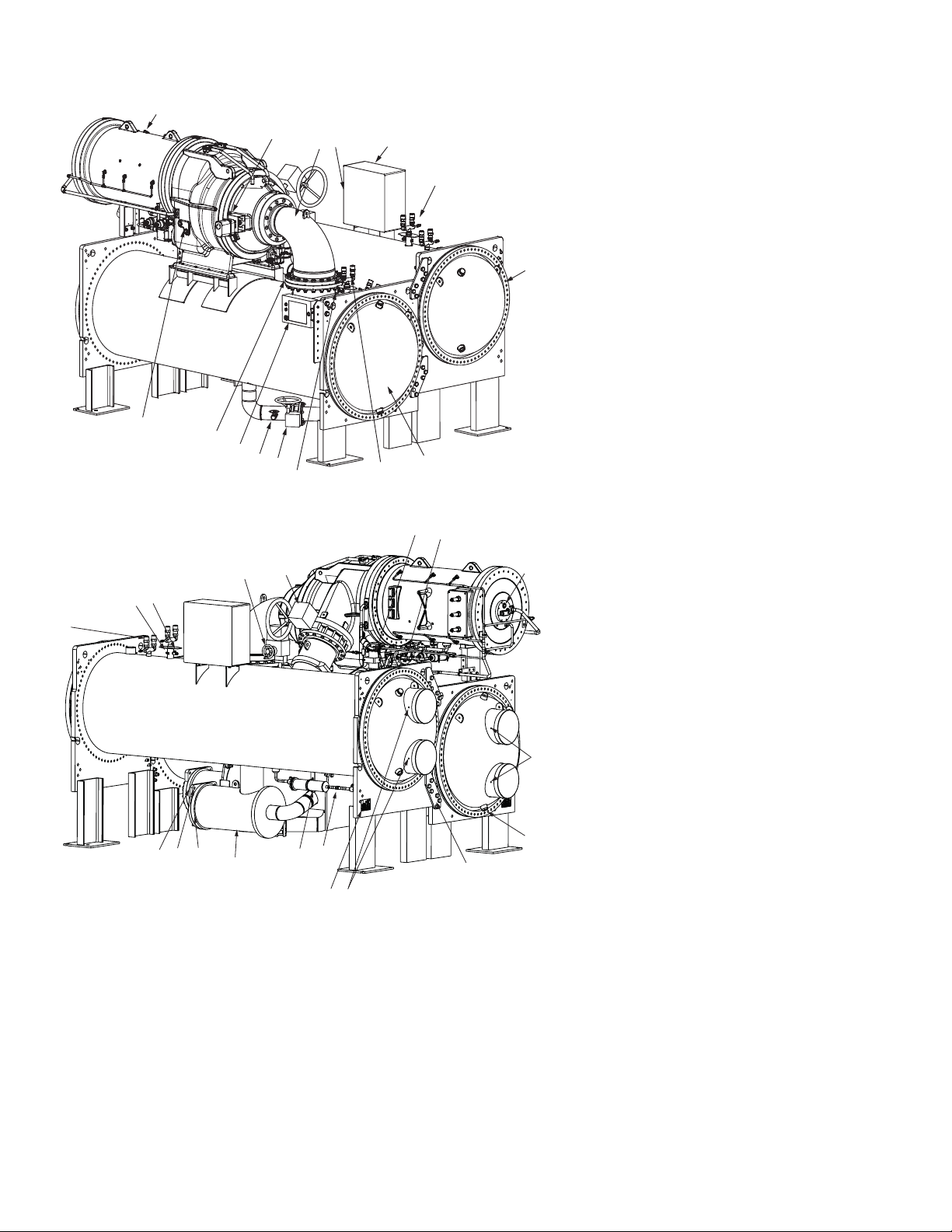
CHILLER FAMILIARIZATION (Fig. 1 and 2)
Chiller Information Nameplate —
nameplate is located on the right side of the chiller control
panel.
The information
System Components — The components include the
cooler and condenser heat exchangers in separate vessels,
motor-compressor, lubrication package, control panel, economizer, and motor starter. All connections from pressure vessels
have external threads to enable each component to be pressure
tested with a threaded pipe cap during factory assembly.
Cooler — This vessel (also known as the evaporator) is lo-
cated underneath the compressor. The cooler is maintained at
lower temperature/pressure so evaporating refrigerant can remove heat from water flowing through its internal tubes.
Condenser — The condenser operates at a higher tem-
perature/pressure than the cooler and has water flowing
through its internal tubes in order to remove heat from the refrigerant.
Motor-Compressor — This component maintains sys-
tem temperature and pressure differences and moves the heatcarrying refrigerant from the cooler to the condenser. The
19XR two-stage frame 6 and frame 7 compressors are twostage compressors with two impellers.
Control Panel — The control panel is the user interface
for controlling the chiller. It regulates the chiller’s capacity as
required to maintain proper leaving chilled water temperature.
The control panel:
• registers cooler, condenser, and lubricating system
pressures
• shows chiller operating condition and alarm shutdown
conditions
• records the total chiller operating hours
• sequences chiller start, stop, and recycle under micropro-
cessor control
• displays status of motor starter
• provides access to other CCN (Carrier Comfort Net-
• supports languages that may be pre-installed at factory,
®
work
) devices and energy management systems
including English, Chinese, Spanish, French, and
German.
4
Page 5
Economizer — This chamber reduces the refrigerant pres-
636
Motor Size Code
Compressor Frame Size 6
G (2250 HP, copper rotor)
H (2375 HP, copper rotor)
J (2500 HP, copper rotor)
K (2625 HP, copper rotor)
L (2750 HP, copper rotor)
N — 1500 HP
P — 1625 HP
Q — 1750 HP
R — 1875 HP
S — 2000 HP
T — 2100 HP
Compressor Frame Size 7
U — 2250 HP
V — 2375 HP
W — 2500 HP
X — 2625 HP
Y — 2750 HP
Z — 2900 HP
Motor V oltage Code
Code Volts-Phase-Hertz
Special Order Indicator
– — Standard
S — Special Order
M
N7
Gear Code
Compressor Frame Size 6
E
J
M
P
Compressor Frame Size 7
R
T
V
X
Y
Compressor Size Code
Frame Size (12th Digit)
6 — Frame Size 6
7 — Frame Size 7
Centrifugal Liquid Chiller
Description
19XR– — High Efficiency Semi-Hermetic
19XR–
A45
A47
Cooler Size Code (Digits 6, 7, 8)
A40-A42
A45-A47
A4A-A4C*
A4F-A4H*
A60-A62
A65-A67
A6A-A6C*
A6F-A6H*
B60-B62
B65-B67
B80-B82**
B85-B-87**
B6A-B6C*
B6F-B6H*
B8A-B8C**
B8F-B8H
C60-C62
C65-C67
C6A-C6C*
C6F-C6H*
Condenser Size Code (Digits 9, 10, 11)
A40-A42
A45-A47
A4A-A4C*
A4F-A4H*
A60-A62
A65-A67
A6A-A6C*
A6F-A6H*
B40-B42
B45-B47
B4A-B4C*
B4F-B4H*
B60-B62
B65-B67
B6A-B6C*
B6F-B6H*
C60-C62
C65-C67
C80-C82 **
C85-C87**
C6A-C6C*
C6F-C6H*
C8A-C8C**
CF-C8H
D60-D62
D65-D67
D6A-D6C*
D6F-D6H*
Shroud Size (13th Digit)
1
2
3
4 (Frame Size 6 Only)
Impeller Diameter (14th Digit)
2
4
6
8
0
3000-3-50
3300-3-50
6300-3-50
10000-3-50
11000-3-50
2400-3-60
3300-3-60
4160-3-60
6900-3-60
11000-3-60
13800-3-60
—
—
—
—
—
—
—
—
—
—
—
4
5
6
7
8
E
F
G
H
J
K
Fig. 1 — 19XR Two-Stage Chiller Model Number Nomenclature
*Frame sizes with A-C and F-H are with 1-in. OD evaporator tubing.
sure to an intermediate level between the cooler and condenser
vessels. In the economizer, vapor is separated from the liquid,
the separated vapor flows to the second stage of the compressor, and the liquid flows into the cooler. The energy removed
from the vaporized refrigerant in the economizer allows the
liquid refrigerant in the cooler to absorb more heat when it
evaporates and benefits the overall cooling efficiency cycle.
Free-Standing Starter — The starter allows for the
proper start and disconnect of electrical energy for the compressor-motor, oil pump, oil heater, and control panel.
Week of Year
Year of Manufacture
SERIAL NUMBER STRUCTURE
5
12 15 Q 19843
Unique Number
Place of Manufacture
a19-2271
Page 6
15
1
2
3
4
5
6
7
8
9
10
11
12
13
14
16
17
18
19
20
21
22
23
24
25
26
27
28
29
30
31
32
33
34
Fig. 2 — Typical 19XR 1500-3000 Ton Two-Stage Compressor Chiller Compone nts
(XR6 Shown)
REAR VIEW
FRONT VIEW
LEGEND
1—Guide Vane Actuator
2—Suction Elbow
3—Chiller Identification Nameplate
4—Control Panel
5—Condenser Auto. Reset Relief Valves
6—Condenser Return End Waterbox Cover
7—Cooler Return End Waterbox Cover
8—Cooler Auto. Reset Relief Valves
9—Cooler Pressure Transducer
10 — Liquid Line Isolation Valve (Optional)
11 — Refrigerant Storage Tank Connection Valve
12 — HMI (Human Machine Interface) Control Panel
13 — Typical Flange Connection
14 — Oil Level Sight Glasses
15 — Compressor Motor Housing
LEGEND
16 — Oil Cooler
17 — Oil Drain Changing Valve (Hidden)
18 — Motor Sight Glass
19 — Cooler In/Out Temperature Thermistors
20 — Typical Waterbox Drain Port
21 — Vessel Take-Apart Connector
22 — Condenser In/Out Temperature Thermistors
23 — ASME Nameplate
24 — Refrigerant Moisture/Flow Indicator
25 — Refrigerant Filter/Drier
26 — High Side Float Chamber
27 — High Side Float Ball Valve Assembly (Inside)
28 — Economizer Assembly
29 — Economizer Float Ball Assembly (Inside)
30 — Cooler Auto. Reset Relief Valve
31 — Condenser Pressure Transducer
32 — Refrigerant Charging Valve/Pumpout
Connection
33 — Damper Valve
34 — Discharge Isolation Valve (Optional)
6
Page 7
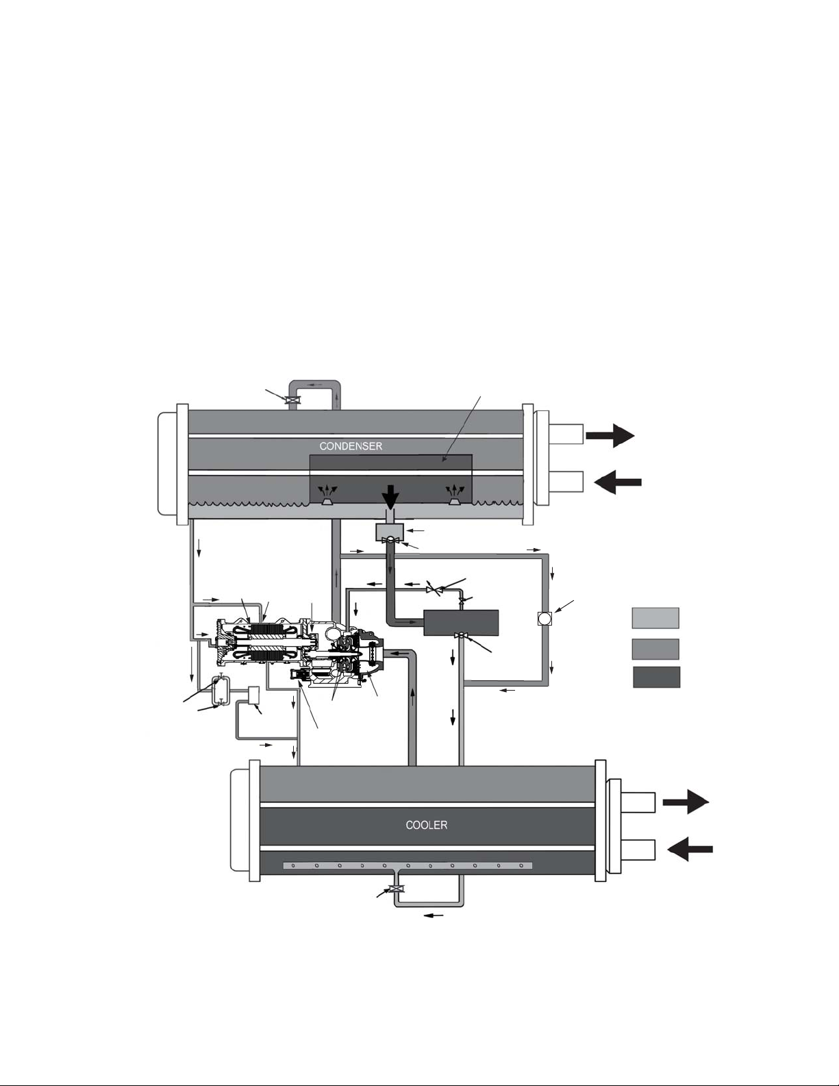
REFRIGERATION CYCLE
Fig. 3 — Refrigeration Cycle — 19XR Two-Stage Compressor Frame Sizes 6 and 7
The compressor continuously draws refrigerant vapor from
the cooler at a rate set by the amount of guide vane opening. As
the compressor suction reduces the pressure in the cooler, the
remaining refrigerant boils at a fairly low temperature (typically 38 to 42 F [3 to 6 C]). The energy required for boiling is obtained from the water flowing through the cooler tubes. With
heat energy removed, the water becomes cold enough to use in
an air-conditioning circuit or process liquid cooling.
After taking heat from the water, the refrigerant vapor is
compressed. Compression adds still more heat energy and the
refrigerant is quite warm (typically 98 to 102 F [37 to 40 C])
when it is discharged from the compressor into the condenser.
Relatively cool (typically 65 to 90 F [18 to 32 C]) water
flowing into the condenser tubes removes heat from the refrigerant, and the vapor condenses to liquid. The liquid refrigerant
passes through orifices into the FLASC (flash subcooler)
chamber. Since the FLASC chamber is at a lower pressure, part
of the liquid refrigerant flashes to vapor, thereby cooling the remaining liquid. The FLASC vapor is recondensed on the tubes
which are cooled by entering condenser water. The liquid
ISOLATION
VALVE
(OPTION)
drains into a high side float valve chamber between the FLASC
chamber and the economizer. The refrigerant is then metered
into the economizer. In the economizer, due to lower pressure,
as liquid enters the chamber, some liquid will flash into a vapor
and cool the remaining liquid. The separated vapor flows to the
second stage of the compressor for greater cycle efficiency. A
damper valve located on the economizer line to the compressor
acts as a pressure regulating device to stabilize low load, low
condensing pressure operating conditions. The damper will
back up gas flow and thereby raises the economizer pressure to
permit proper refrigerant flow through the economizer valve
during those conditions.
The cooled liquid left in the economizer flows through a
low side float valve and then into the cooler. The float valve
forms a liquid seal to keep vapor from entering the cooler. Liquid refrigerant passes through the low side valve into the cooler. The refrigerant is now at a temperature and pressure at
which the cycle began. Fig. 3 summarizes the refrigeration
cycle.
FLASC CHAMBER
THERMOSTATIC
EXPANSION
VALVE (TXV)
ROTOR
ORIFICE
FITTING
OIL COOLER
TRANSMISSION
IMPELLERS
BACK PRESSURE
ORIFICE (INTEGRAL
TO MOTOR SHELL)
COMPRESSOR
HIGH SIDE FLOAT CHAMBER
HIGH SIDE FLOAT VALVE
DAMPER
VALVE
REFRIGERANT
ISOLATION VALVE
ECONOMIZER
LOW SIDE
FLOAT VALVE
HOT GAS BYPASS
HGBP
VALVE
CONDENSER
WATER
REFRIGERANT
LIQUID
REFRIGERANT
VAPOR
REFRIGERANT
LIQUID/VAPOR
CHILLED
WATER
COOLER
ISOLATION
VALVE
(OPTION)
7
Page 8

MOTOR AND OIL COOLING CYCLE
The motor and the lubricating oil are cooled by liquid refrigerant taken from the bottom of the condenser vessel (Fig. 3 and
4). Refrigerant flow is maintained by the pressure differential
that exists due to compressor operation. After the refrigerant
flows past an isolation valve, an in-line filter, and a sight glass/
moisture indicator, the flow is split between the motor cooling
and oil cooling systems.
Flow to the motor cooling system passes through an orifice
and into the motor. Once past the orifice, the refrigerant is directed over the motor by spray nozzles. The refrigerant collects
in the bottom of the motor casing and is then drained back into
the cooler through the motor refrigerant drain line. An orifice
(in the motor shell) maintains a higher pressure in the motor
shell than in the cooler. The motor is protected by a temperature sensor embedded in the stator windings. An increase in
motor winding temperature past the motor override set point
overrides the temperature capacity control to hold, and if the
motor temperature rises 10 F (5.5 C) above this set point, the
controls close the inlet guide vanes. If the temperature rises
above the safety limit, the compressor shuts down.
Refrigerant that flows to the oil cooling system is regulated
by expansion valves. The expansion valves regulate flow into
the oil/refrigerant plate and frame-type heat exchanger (the oil
cooler in Fig. 3), and control oil temperature to the bearings.
The refrigerant leaving the oil cooler heat exchanger returns to
the chiller cooler.
LUBRICATION CYCLE
Summary —
up a package located partially in the transmission casing of the
compressor-motor assembly. The oil is pumped into a filter
assembly to remove foreign particles and is then forced into an
oil cooler heat exchanger where the oil is cooled to proper operational temperatures. After the oil cooler, part of the flow is
directed to the gears and the high speed shaft bearings; the remaining flow is directed to the motor shaft bearings. Oil drains
into the transmission oil sump to complete the cycle (Fig. 3 and
4).
The oil pump, oil filter, and oil cooler make
Details — Oil is charged into the lubrication system through
a hand valve. Two sight glasses in the oil reservoir permit oil
level observation. Normal oil level is between the middle of the
upper sight glass and the top of the lower sight glass when the
compressor is shut down. The oil level should be visible in at
least one of the 2 sight glasses during operation. Oil sump temperature is displayed on the HMI default screen. During compressor operation, the oil sump temperature ranges between
125 and 150 F (52 and 66 C).
The oil pump suction is fed from the oil reservoir. An oil
pressure relief valve maintains differential pressure in the system at the pump discharge. A range of 18 to 40 psid (124 to
172 kPad) is normal. This differential pressure can be read directly from the default HMI screen. The oil pump discharges
oil to the oil filter assembly. This filter can be closed to permit
removal of the filter without draining the entire oil system. The
oil is then piped to the oil cooler heat exchanger. The oil cooler
uses refrigerant from the condenser as the coolant. The refrigerant cools the oil to a temperature between 120 and 140 F (49
and 60 C).
As the oil leaves the oil cooler, it passes the oil pressure
transducer and the sensor for the refrigerant expansion valve on
the oil cooler. The oil is then divided. Part of the oil flows to the
thrust bearing, forward pinion bearing, and gear spray. The rest
of the oil lubricates the motor shaft bearings and the rear pinion
bearing. The oil temperature is measured in the bearing housing as it leaves the bearings. The oil then drains into the oil reservoir at the base of the compressor. The control measures the
temperature of the oil in the sump and maintains the temperature during shutdown. This temperature is read on the HMI default screen. See the Controls Operation and Troubleshooting
Manual for details.
During the chiller start-up, the oil pump is energized and
provides 40 seconds of lubrication to the bearings after pressure is verified before starting the compressor. During shutdown, the oil pump runs for 60 seconds to ensure lubrication as
the compressor coasts to a stop.
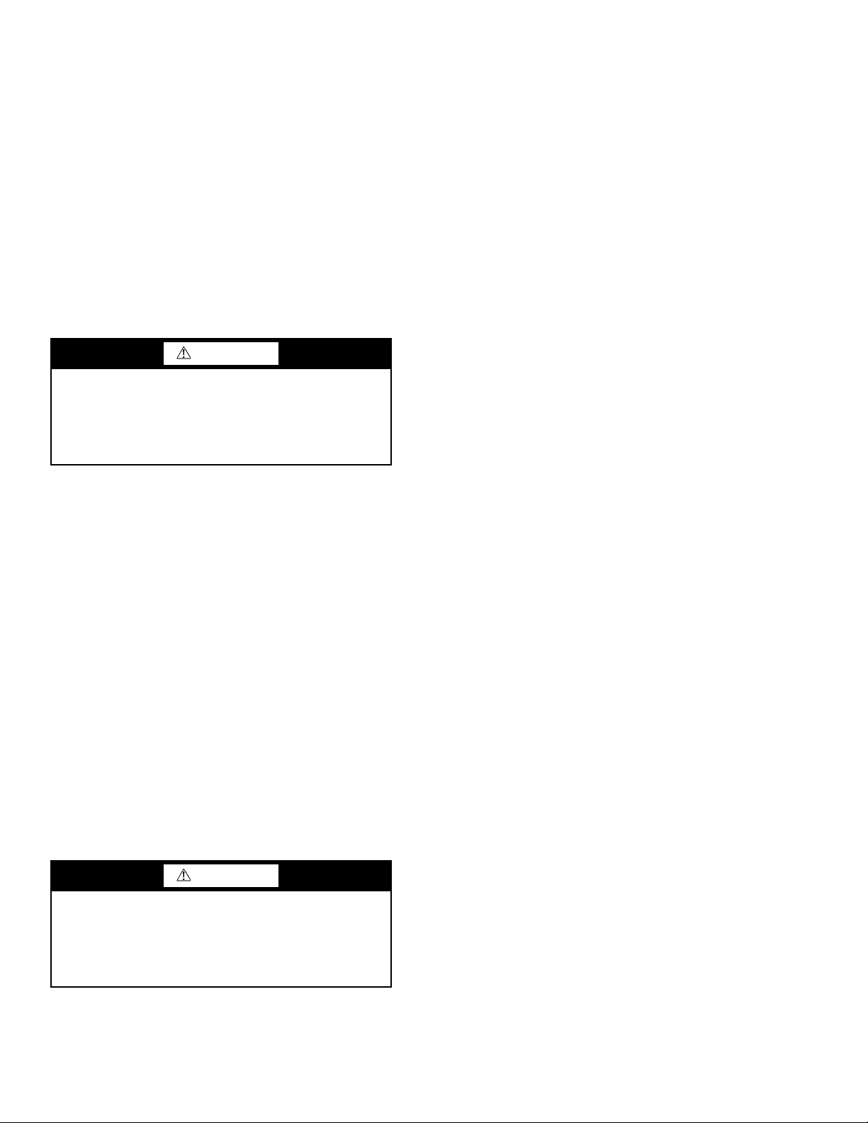
The oil pump is a gerotor-style pump with external filters.
A gerotor pump has two rotors, one is inside the other; their
center points are offset with respect to each other. This type of
pump provides a smooth continuous flow. It is also quieter than
other designs. See Fig. 5.
Bearings — The 19XR compressor assemblies include a
combination of radial bearings and thrust bearings. The low
speed shaft assembly is supported by two journal bearings located on each end of the low speed shaft. The bearing closer to
the bull gear includes a smaller babbitted thrust face, designed
to handle axial forces.
Oil Reclaim System — The oil reclaim system returns
oil lost from the compressor housing back to the oil reservoir
by recovering the oil from 2 areas on the chiller. The guide
vane housing is the primary area of recovery. Oil is also recovered by skimming it from the operating refrigerant level in the
cooler vessel.
PRIMARY OIL RECOVERY MODE — Oil is normally recovered through the guide vane housing on the chiller. This is
possible because oil is normally entrained with refrigerant in
the chiller. As the compressor pulls the refrigerant up from the
cooler into the guide vane housing to be compressed, the oil
normally drops out at this point and falls to the bottom of the
guide vane housing where it accumulates. Using discharge gas
pressure to power an eductor, the oil is drawn from the housing
and is discharged into the oil reservoir.
SECONDARY OIL RECOVERY METHOD — The secondary method of oil recovery is significant under light load
conditions, when the refrigerant going up to the compressor
suction does not have enough velocity to bring oil along. Under
these conditions, oil collects in a greater concentration at the
top level of the refrigerant in the cooler. Using discharge gas to
power eductors, this oil and refrigerant mixture is skimmed
from the side of the cooler and is then drawn up to the guide
vane housing. There is a filter in this line. Because the guide
vane housing pressure is much lower than the cooler pressure,
the refrigerant boils off, leaving the oil behind to be collected
by the primary oil recovery method.
8
Page 9
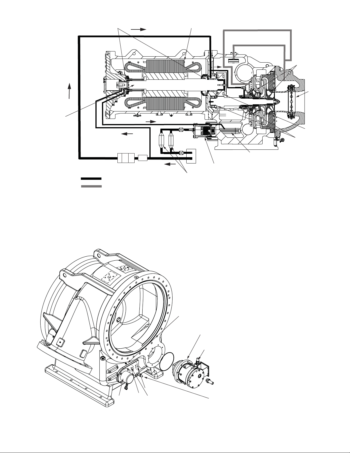
10
Fig. 4 — 19XR Two-Stage Compressor Lubrication System
LEGEND
1—Motor Stator 6— Oil Heater
2—Impellers 7— Oil Pump
3—Variable Inlet Guide Vanes 8— Oil Filters
4—Transmission 9— Motor Rotor
5—High Speed Shaft Bearings 10— Motor Shaft Bearings
a19-
1
2
3
4
5
6
7
8
Fig. 5 — Gerotor Oil Pump
a19-2116
LEGEND
1—Gerotor Oil Pump
2—Oil Pressure Regulator Valve
3—Oil Sump Pressure Transducer
4—Oil Sump Drain Valve
5—High Speed Compressor End Bearing,
Temperature Terminal Block
6—Low Speed Compressor End Bearing,
Temperature Cable
7—Compressor Oil Sump Temperature
8—Oil Heater
9
OIL LINE
VENT LINE
1
2
3
4
5
6
7
8
9
Page 10
STARTING EQUIPMENT
The 19XR chiller requires a motor starter to operate the centrifugal hermetic compressor motor, the oil pump, and various
auxiliary equipment components. The starter is the main field
wiring interface for the contractor.
See Carrier’s specification for specific starter requirements.
All starters must meet these specifications in order to properly
start and satisfy mechanical safety requirements.
It is possible that there are two separate circuit breakers inside the starter. These include (1) the main compressor motor
circuit breaker, and (2) a circuit breaker which provides power
to the chiller control panel. The latter is typically wired in parallel with the first so that power is provided to those services
when the main breaker is open. The disconnect switch on the
starter front cover is connected to the main breaker. Typically,
separate 3-phase power sources as per job requirements are
supplied to the control panel to power the oil pump, heater, and
controls.
The display on the front of the solid-state starter is useful for
troubleshooting and starter checkout. The display indicates:
• line voltage
• control voltage status
• power indication
• proper phasing for rotation
• start circuit energized
• ground fault
• current unbalance
•run state
The starter is further explained in the Check Starter section,
page 19.
Freestanding Medium Voltage VFD
(Optional) —
can be combined with a VFD (variable frequency drive). This
option is a freestanding, medium voltage current source drive
that does not require a transformer between the power source
and the drive. The drive meets IEEE-519 specifications.
For optimum efficiency, the 19XR chiller
WARNING
The main circuit breaker on the front of the starter disconnects the main motor power only. Power may be still energized for other circuits. Always check wiring diagrams
before initiating any work on the chiller and follow applicable lock-out/tag-out procedures. Failure to disconnect
power will result in personal injury.
All starters must include a Carrier control module called the
Integrated Starter Module (ISM). This module controls and
monitors all aspects of the starter. See the Controls Operation
and Troubleshooting guide for additional ISM information.
Contact Carrier’s Replacement Component Division (RCD)
for replacement parts.
Solid-State Starter (Optional) — The 19XR chiller
may be equipped with a solid-state, reduced-voltage starter.
This starter’s primary function is to provide on-off control of
the compressor motor. This type of starter reduces the peak
starting torque, controls the motor inrush current, and decreases
mechanical shock. This capability is summed up by the phrase
“soft starting.” Consult E-Cat for full information about starter
offerings. The solid-state starter manufacturer’s name is located inside the starter access door.
A solid-state, reduced-voltage starter operates by reducing
the starting voltage. The starting torque of a motor at full voltage is typically 125% to 175% of the running torque. When the
voltage and the current are reduced at start-up, the starting
torque is reduced as well. The object is to reduce the starting
voltage to adjust the voltage necessary to develop the torque required to get the motor moving. The voltage is reduced by silicon controlled rectifiers (SCRs). The voltage and current are
then ramped up in a desired period of time. Once full voltage is
reached, a bypass contactor is energized to bypass the SCRs.
WARNING
When voltage is supplied to the solid-state circuitry (CB1
is closed), the heat sinks in the starter as well as the wires
leading to the motor and the motor terminal are at line voltage. Do not touch the heat sinks, power wiring, or motor
terminals while voltage is present or serious injury will
result.
CONTROLS
Definitions
ANALOG SIGNAL — An analog signal varies in proportion
to the monitored source. It quantifies values between operating
limits. (Example: A temperature sensor is an analog device because its resistance changes in proportion to the temperature,
generating many values.)
DISCRETE SIGNAL — A discrete signal is a 2-position representation of the value of a monitored source. (Example: A
switch produces a discrete signal indicating whether a value is
above or below a set point or boundary by generating an on/off,
high/low, or open/closed signal.)
General — The 19XR centrifugal liquid chiller contains a
microprocessor-based control center that monitors and controls
all operations of the chiller. The microprocessor control system
matches the cooling capacity of the chiller to the cooling load
while providing state-of-the-art chiller protection. The system
controls cooling load within the set point plus the deadband by
sensing the leaving chilled water or brine temperature and regulating the inlet guide vane via a mechanically linked actuator
motor. The guide vane is a variable flow pre-whirl assembly
that controls the refrigeration effect in the cooler by regulating
the amount of refrigerant vapor flow into the compressor. An
increase in guide vane opening increases capacity. A decrease
in guide vane opening decreases capacity. The microprocessorbased control center protects the chiller by monitoring the digital and analog inputs and executing capacity overrides or safety
shutdowns, if required.
PIC 5 System Components — The chiller control
system is called the PIC 5 (Product Integrated Control 5). See
Table 1. As with previous PIC versions, the PIC 5 system controls the operation of the chiller by monitoring all operating
conditions. The PIC 5 control system can diagnose a problem
and let the operator know what the problem is and what to
check. It promptly positions the guide vanes to maintain leaving chilled water temperature. It can interface with auxiliary
equipment such as pumps and cooling tower fans to turn them
on when required. It continually checks all safeties to prevent
any unsafe operating condition. It also regulates the oil heater
while the compressor is off and regulates the hot gas bypass
valve, if installed. The PIC 5 controls provide critical protection for the compressor motor and control the motor starter.
10
Page 11
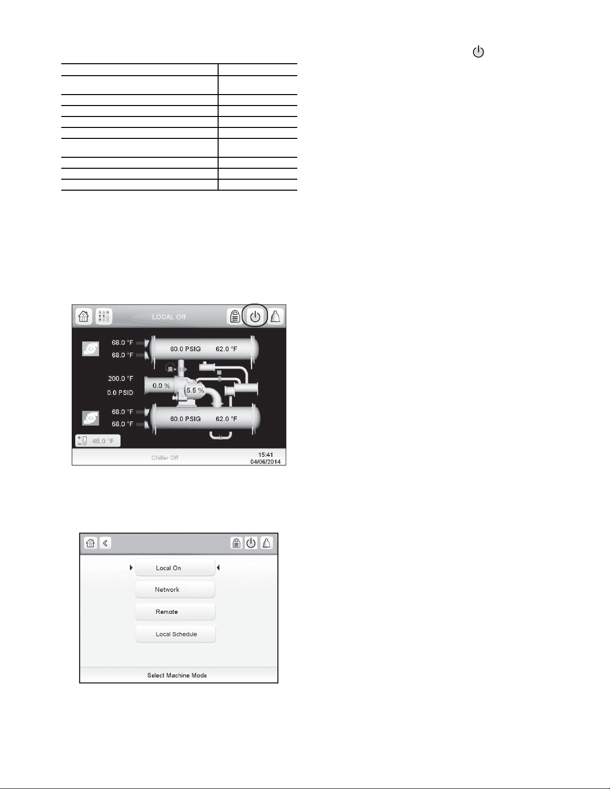
Table 1 — Major PIC 5 Components and
Fig. 6 — Chiller Start/Stop Icon
Fig. 7 — Local On
a19-2118
Panel Locations
PIC 5 COMPONENT PANEL LOCATION
Chiller Human Machine Interface (HMI)
and Display
Integrated Starter Module (ISM) Starter Cabinet
Chiller IO Boards Control Panel
Oil Heater Contactor (1C) Control Panel
Oil Pump Contactor (2C) Control Panel
Hot Gas Bypass Relays (HCLR, HOPR)
(Optional)
Control Transformers (T1, T2, T3) Control Panel
Temperature Sensors See Fig. 2 and Fig. 5
Pressure Transducers See Fig. 2 and Fig. 5
HMI Control Panel
Control Panel
NOTE: For detailed information about the PIC 5 HMI (human
machine interface), see the 19XR with PIC 5 Controls Operation and Troubleshooting manual.
START-UP/SHUTDOWN/
RECYCLE SEQUENCE
Local Start/Stop Control —
start-up) is initiated by pressing the the gray Start/Stop icon on
the HMI interface. See Fig. 6.
This initiates the PIC 5 starting sequence by displaying the list
of operating modes. Press Local On to initiate start-up. See
Fig. 7.
Local start-up (or manual
When start-up is initiated the status screen displays the start-
up progress and the Start/Stop icon blinks green.
Once local start-up begins, the PIC 5 control system performs a series of pre-start tests to verify that all pre-start alerts
and safeties are within acceptable limits. Table 2 shows appropriate Prestart Alerts/Alarms conditions. If a test is not successful, the start-up is delayed or aborted. If the tests are successful,
the start-up will be in progress and the COMPRESSOR RUN
STATUS shall be “Startup.” The control shall then energize the
chilled water/brine pump relay.
Five seconds later, the condenser pump relay energizes.
Thirty seconds later the PIC 5 control system monitors the
chilled water and condenser water flow devices and waits until
the WATER FLOW VERIFY TIME (operator-configured, default 5 minutes) expires to confirm flow. After flow is verified,
the chilled water temperature is compared to CONTROL
POINT plus 1/2 CHILLED WATER DEADBAND. If the temperature is less than or equal to this value, the PIC 5 control
system turns off the condenser pump relay and goes into a Recycle mode.
If the water/brine temperature is high enough, the start-up
sequence continues and checks the guide vane position. If the
guide vanes are more than 4% open, the start-up waits until the
PIC 5 control system closes the vanes. If the vanes are closed
and the oil pump pressure is less than 4 psi (27.6 kPa), the oil
pump relay energizes. The PIC 5 control system then waits until the oil pressure (OIL PRESS VERIFY TIME, operator-configured, default of 40 seconds) reaches a maximum of 18 psi
(124 kPa). After oil pressure is verified, the PIC control system
waits 40 seconds, and the compressor start relay (1CR) energizes to start the compressor.
Compressor ontime and service ontime timers start, and the
compressor STARTS IN 12 HOURS counter and the number of
starts over a 12-hour period counter advance by one.
Failure to verify any of the requirements up to this point will
result in the PIC 5 control system aborting the start and displaying the applicable pre-start alert alarm state number near the
bottom of the home screen on the HMI panel. A prestart failure
does not advance the STARTS IN 12 HOURS counter. Any fail-
ure after the 1CR relay has energized results in a safety shutdown, advances the starts in 12 hours counter by one, and displays the applicable shutdown status on the display.
The minimum time to complete the entire prestart sequence
is approximately 185 seconds. See Fig. 8 for normal start-up
timing sequence. See Table 2 for a list of prestart checks.
Unit Start/Stop
NOTE: Prior to start-up the start-to-start timer and the stop-tostart timer must have elapsed and all alarms must be cleared
(see Troubleshooting Guide section on page 42).
11
Page 12
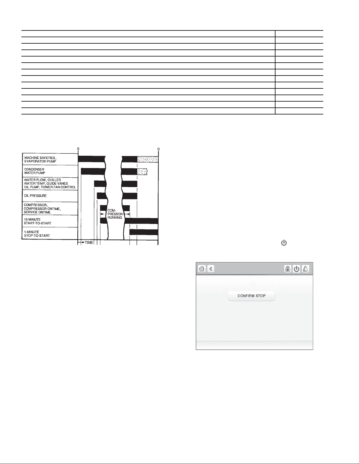
Table 2 — Prestart Checks
AB
CDE
F
G
O/A
A—START INITIATED: Pre-start checks are made; evaporator pump
started.*
B—Condenser water pump started (5 seconds after A).
C—Water flows verified (30 seconds to 5 minutes maximum after B).
Chilled water temperatures checked against control point. Guide
vanes checked for closure. Oil pump started; tower fan control
enabled.
D—Oil pressure verified (15 seconds minimum, 300 seconds maximum
after C).
E—Compressor motor starts; compressor ontime and service ontime
start, 15-minute inhibit timer starts (10 seconds after D), total compressor starts advances by one, and the number of starts over a
12-hour period advances by one.
F—SHUTDOWN INITIATED — Compressor motor stops; compressor
ontime and service ontime stop, and 1-minute inhibit timer starts.
G—Oil pump and evaporator pumps deenergized (60 seconds after F).
Condenser pump and tower fan control may continue to operate if
condenser pressure is high. Evaporator pump may continue if in
RECYCLE mode.
O/A — Restart permitted (both inhibit timers expired: minimum of 15 min-
utes after E; minimum of 1 minute after F).
Fig. 8 — Control Timing Sequence
for Normal Start-Up
* Auto Restart After Power Failure Timing sequence will be faster.
Fig. 9 — Confirm Stop
a19-2122
Unit Start/Stop
PRESTART CHECK CONDITION* STATE NUMBER
STARTS IN 12 HOURS 8 (not counting recycle restarts or auto restarts after power failure) Alert – 100
OIL SUMP TEMP 140° F (60° C) and OIL SUMP TEMP EVAP_SAT + 50° F (27.8° C) Alert – 101
COND PRESSURE COND PRESS OVERRIDE – 20 psi Alert – 102
#RECYCLE RESTARTS LAST 4 HOURS > 5 Alert – 103
COMP BEARING TEMPS COMP BEARING ALERT– 10° F (5.6° C) Alarm – 230
COMP MOTOR WINDING TEMP COMP MOTOR WINDING– 10° F (5.6° C) Alarm – 231
COMP DISCHARGE TEMPERATURE COMP DISCHARGE ALERT– 10° F (5.6° C) Alarm – 232
EVAP_SAT <Evap trip point** + EVAP OVERRIDE DELTA T Alarm – 233
EVAP REFRIG LIQUID TEMP <Evap trip point** + EVAP OVERRIDE DELTA T Alarm – 233
AVERAGE LINE VOLTAGE UNDERVOLTAGE THRESHOLD Alarm – 234
AVERAGE LINE VOLTAGE OVERVOLTAGE THRESHOLD Alarm – 235
CHECK FOR GUIDE VANE CALIBRATION Alarm – 236
* If Prestart Check Condition is True, then resulting State is as indicated in the State Number column.
†
See the Controls Operation and Troubleshooting guide for alarm and alert codes.
**Evap trip point = 33 F (0.6 C) (water) or EVAP REFRIG TRIPPOINT (brine)
The oil heater relay is energized whenever the chiller compressor is off and the oil sump temperature is less than 140 F
(60 C) or the oil sump temperature is less than the evaporator
saturated refrigerant temperature plus 53° F (29.4° C). The oil
heater is turned off when either of the following conditions is
true:
• Oil sump temperature is more than 152 F (66.7 C)
• Oil sump temperature is more than 144 F (62.2 C) and
more than the evaporator saturated refrigerant tempera-
ture plus 55° F (30.6° C)
The oil heater is always off when the compressor is running.
The oil pump is also energized for 30 seconds after each 30
minutes of oil heat relay being energized in order to stir the oil
for more evenly distributed heating.
Shutdown — The unit can be stopped locally using the
HMI by pressing the green Start/Stop icon . The Unit Start/
Stop screen is displayed. Press Confirm Stop (see Fig. 9).
†
Lubrication Control — As part of the prestart checks
executed by the controls, the oil sump temperature is compared
to the evaporator saturated refrigerant temperature. If the oil
temperature is less than 140 F (60 C) and less than evaporator
saturated refrigerant temperature plus 50° F (27.8° C), the
start-up will be delayed until either of these conditions is no
longer true. Once this temperature is confirmed, the start-up
continues.
12
Page 13
BEFORE INITIAL START-UP
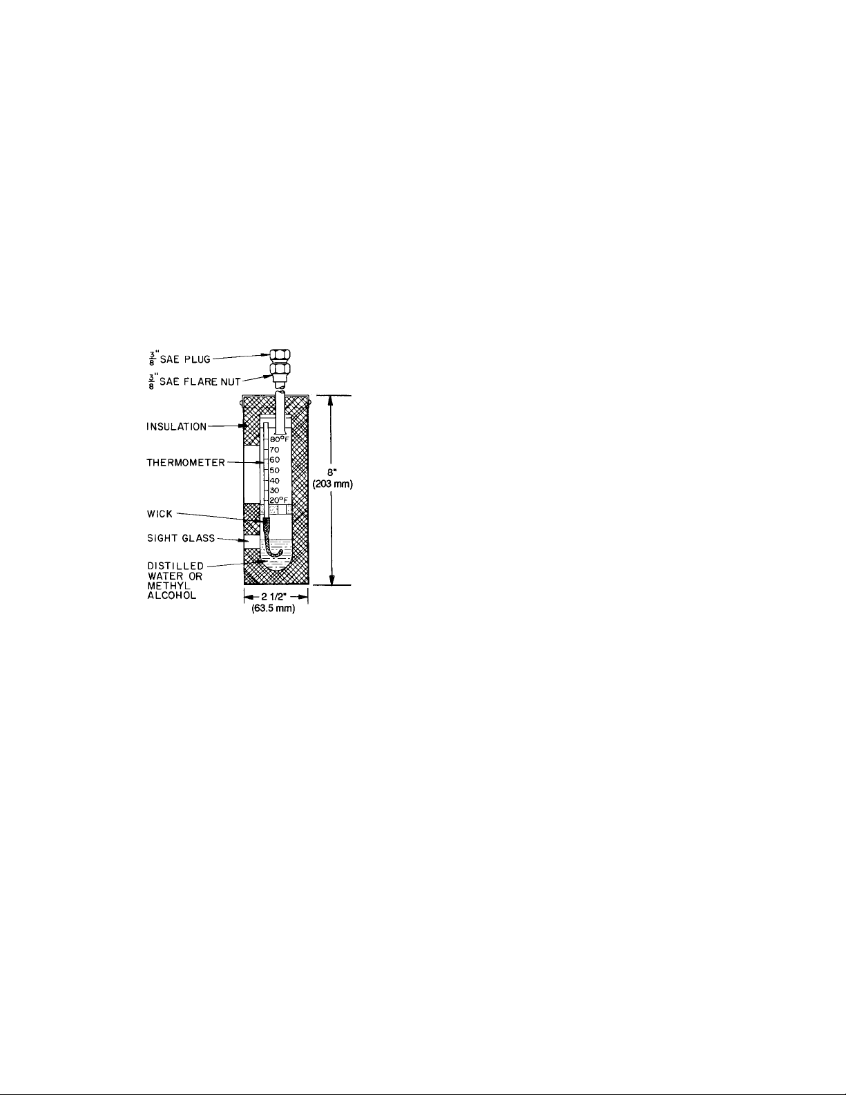
Fig. 10 — Typical Wet-Bulb Type
Vacuum Indicator
Job Data Required
• list of applicable design temperatures and pressures
(product data submittal)
• chiller certified prints
• starting equipment details and wiring diagrams
• diagrams and instructions for special controls or options
• 19XR Installation Instructions
Equipment Required
• mechanic’s tools (refrigeration)
• digital volt-ohmmeter (DVM)
• true RMS (root mean square) digital multimeter with
clamp-on current probe or true RMS digital clamp-on
ammeter for at least 480 vac
• electronic leak detector
• absolute pressure manometer or wet-bulb vacuum
indicator (see Fig. 10)
• insulation tester for compressor motor rated at motor
design voltage
Remove Shipping Packaging — Remove any pack-
aging material from the unit and starter.
Open Oil Circuit Valves — Check to ensure the oil fil-
ter isolation valves are open by removing the valve cap and
checking the valve stem.
Tighten All Gasketed Joints — Gaskets normally
relax by the time the chiller arrives at the jobsite. Tighten all
gasketed joints to ensure a leak-tight chiller (does not apply to
refrigerant joints covered by factory insulation). Gasketed
joints (excluding O-rings) may include joints at some or all of
the following:
• waterbox covers
• compressor suction elbow flanges (at compressor and at the
cooler)
• compressor discharge flange
• compressor discharge line spacer (both sides) if no isolation
valve
• cooler inlet line spacer (both sides) if no isolation valve
• hot gas bypass valve (both sides of valve)
• hot gas bypass flange at compressor
See Tables 3 and 4 for bolt torque requirements.
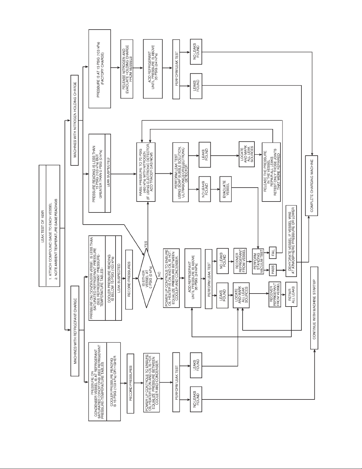
Check Chiller Tightness — Figure 11 outlines the
proper sequence and procedures for leak testing.
The 19XR chillers are shipped with the refrigerant con-
tained in the condenser shell and the oil charge in the compressor. The cooler is shipped with a 15 psig (103 kPa) refrigerant
charge. Units may be ordered with the refrigerant shipped separately, along with a 15 psig (103 kPa) nitrogen-holding charge
in each vessel.
To determine if there are any leaks, the chiller should be
charged with refrigerant. Use an electronic leak detector to
check all flanges and solder joints after the chiller is pressurized. If any leaks are detected, follow the leak test procedure
(page 16).
If the chiller is spring isolated, keep all springs blocked in
both directions to prevent possible piping stress and damage
during the transfer of refrigerant from vessel to vessel during
the leak test process, or any time refrigerant is being transferred. Adjust the springs when the refrigerant is in operating
condition and the water circuits are full.
13
Page 14
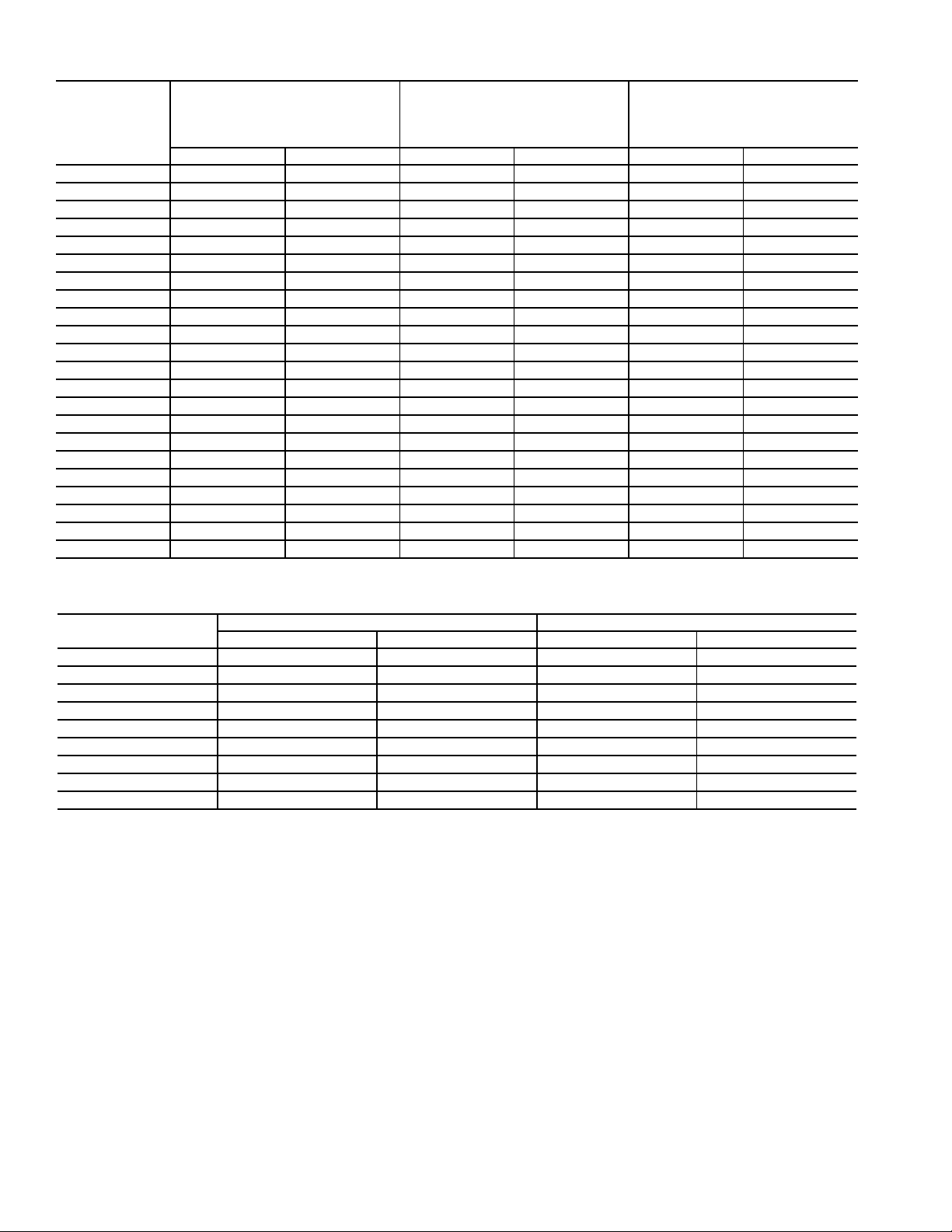
Table 3 — Bolt Torque Requirements, Foot Pounds
SAE 8
HEX HEAD
SA354 GR BD
BOLT SIZE
(in.)
SAE 2, A307 GR A
HEX HEAD
NO MARKS
LOW CARBON STEEL
SOCKET HEAD OR HEX
WITH 3 RADIAL LINES, OR SA499
MEDIUM CARBON STEEL
SAE 5
WITH 6 RADIAL LINES OR
MEDIUM CARBON STEEL
MINIMUM MAXIMUM MINIMUM MAXIMUM MINIMUM MAXIMUM
1
/
4
5
/
16
3
/
8
7
/
16
1
/
2
9
/
16
5
/
8
3
/
4
7
/
8
46 69913
811 13182028
13 19 22 31 32 46
21 30 35 50 53 75
32 45 53 75 80 115
46 65 75 110 115 165
65 95 105 150 160 225
105 150 175 250 260 370
140 200 265 380 415 590
1 210 300 410 580 625 893
1
/
1
8
1
/
1
4
3
1
/
8
1
/
1
2
5
/
1
8
3
1
/
4
7
/
1
8
330 475 545 780 985 1,410
460 660 770 1,100 1,380 1,960
620 885 1,020 1,460 1,840 2,630
740 1060 1,220 1,750 2,200 3,150
1010 1450 1,670 2,390 3,020 4,310
1320 1890 2,180 3,110 3,930 5,610
1630 2340 2,930 4,190 5,280 7,550
2 1900 2720 3,150 4,500 5,670 8,100
1
/
2
4
1
/
2
2
3
/
2
4
2180 3120 4,550 6,500 8,200 11,710
3070 4380 5,000 7,140 11,350 16,210
5120 7320 8,460 12,090 15,710 22,440
3 6620 9460 11,040 15,770 19,900 28,440
Table 4 — Bolt Torque Requirements, Foot Pounds (Metric Bolts)
BOLT SIZE
(METRIC)
MINIMUM MAXIMUM MINIMUM MAXIMUM
M4 1.75 2.5 2.5 3.5
M6 69812
M8 14 20 20 30
M10 28 40 40 57
M12 48 70 70 100
M16 118 170 170 240
M20 230 330 330 470
M24 400 570 570 810
M27 580 830 820 1175
CLASS 8.8 CLASS 10.9
14
Page 15
5 AND 6)
5 AND 6)
Fig. 11 — 19XR Leak Test Procedures
a19-1151tf.eps
15
Page 16
Refrigerant Tracer — Carrier recommends the use of an
environmentally acceptable refrigerant tracer for leak testing
with an electronic detector.
Ultrasonic leak detectors can also be used if the chiller is
under pressure.
WARNING
Do not use air or oxygen as a means of pressurizing the
chiller. Mixtures of HFC-134a and air can undergo
combustion, resulting in equipment damage and possible
personal injury.
Leak Test Chiller — Due to regulations regarding refrig-
erant emissions and the difficulties associated with separating
contaminants from the refrigerant, Carrier recommends the
following leak test procedure. Refer to Tables 5 and 6 for refrigerant pressure/temperature values.
1. If the pressure readings are normal for the chiller
condition:
a. Evacuate the holding charge from the vessels, if
present.
b. Raise the chiller pressure, if necessary, by adding
refrigerant until pressure is at the equivalent saturated pressure for the surrounding temperature.
Follow pumpout procedures in the Transfer Refrigerant from Pumpout Storage Tank to Chiller section, Steps 1a-e, page 34.
CAUTION
Never charge liquid refrigerant into the chiller if the pressure in the chiller is less than 35 psig (241 kPa) for HFC134a. Charge as a gas only, with the cooler and condenser
pumps running, until this pressure is reached, using
PUMPDOWN/LOCKOUT (located in the Maintenance
menu) and TERMINATE LOCKOUT mode on the PIC 5
control interface. Flashing of liquid refrigerant at low pressures can cause tube freeze-up and considerable damage.
c. Leak test chiller as outlined in Steps 3 to 9.
2. If the pressure readings are abnormal for the chiller condition:
a. Prepare to leak test chillers shipped with refriger-
ant (Step 2h).
b. Check for large leaks by connecting a nitrogen bottle
and raising the pressure to 30 psig (207 kPa). Soap
test all joints. If the test pressure holds for 30 minutes,
prepare the test for small leaks (Steps 2g and 2h).
c. Plainly mark any leaks that are found.
d. Release the pressure in the system.
e. Repair all leaks.
f. Retest the joints that were repaired.
g. After successfully completing the test for large
leaks, remove as much nitrogen, air, and moisture
as possible, given the fact that small leaks may be
present in the system. This can be accomplished by
following the dehydration procedure outlined in
the Chiller Dehydration section, page 18.
h. Slowly raise the system pressure to a maximum of
160 psig (1103 kPa) but no less than 35 psig
(241 kPa) for HFC-134a by adding refrigerant.
Proceed with the test for small leaks (Steps 3 to 9).
3. Check the chiller carefully with an electronic leak detector or soap bubble solution.
4. Leak Determination — If an electronic leak detector indicates a leak, use a soap bubble solution, if possible, to
confirm. Total all leak rates for the entire chiller. Leakage
at rates greater than 0.1% of the total charge per year must
be repaired. Note the total chiller leak rate on the start-up
report.
5. If no leak is found during the initial start-up procedures,
complete the transfer of refrigerant gas from the storage
tank to the chiller. Retest for leaks.
6. If no leak is found after a retest:
a. Transfer the refrigerant to the storage tank and per-
form a standing vacuum test as outlined in the
Standing Vacuum Test section, below.
b. If the chiller fails the standi ng vacuum test, check
for large leaks (Step 2b).
c. If the chiller passes the standing vacuum test,
dehydrate the chiller. Follow the procedure in the
Chiller Dehydration section, page 18. Charge the
chiller with refrigerant.
7. If a leak is found after a retest, pump the refrigerant back
into the storage tank or, if isolation valves are present,
pump the refrigerant into the non-leaking vessel. See the
Transfer Refrigerant from Pumpout Storage Tank to
Chiller section on page 34.
8. Transfer the refrigerant until the chiller pressure is at
18 in. Hg (40 kPa absolute).
9. Repair the leak and repeat the procedure, beginning from
Step 2h, to ensure a leak-tight repair. (If the chiller is
opened to the atmosphere for an extended period, evacuate it before repeating the leak test.)
Standing Vacuum Test — When performing the
standing vacuum test or chiller dehydration, use a manometer
or a wet bulb indicator. Dial gages cannot indicate the small
amount of acceptable leakage during a short period of time.
1. Attach an absolute pressure manometer or wet bulb indicator to the chiller.
2. Evacuate the vessel to at least 18 in. Hg vac (41 kPa
[abs]), using a vacuum pump or the pumpout unit.
3. Valve off the pump to hold the vacuum and record the
manometer or indicator reading.
4. a.
5. Repair the leak, retest, and proceed with dehydration.
If the leakage rate is less than 0.05 in. Hg (0.17 kPa)
in 24 hours, the chiller is sufficiently tight.
b. If the leakage rate exceeds 0.05 in. Hg (0.17 kPa)
24 hours, re-pressurize the vessel and test for leaks
if refrigerant is available. If not, use nitrogen and a
refrigerant tracer. Raise the vessel pressure in increments until the leak is detected. If refrigerant is
used, the maximum gas pressure is approximately
70 psig (483 kPa) for HFC-134a at normal ambient
temperature. If nitrogen is used, limit the leak test
pressure to 160 psig (1103 kPa) maximum.
in
16
Page 17
Table 5 — HFC-134a Pressure —
Temperature (F)
Table 6 — HFC-134a Pressure —
Temperature (C)
TEMPERATURE
(F)
0 6.50
2 7.52
4 8.60
6 9.66
8 10.79
10 11.96
12 13.17
14 14.42
16 15.72
18 17.06
20 18.45
22 19.88
24 21.37
26 22.90
28 24.48
30 26.11
32 27.80
34 29.53
36 31.32
38 33.17
40 35.08
42 37.04
44 39.06
46 41.14
48 43.28
50 45.48
52 47.74
54 50.07
56 52.47
58 54.93
60 57.46
62 60.06
64 62.73
66 65.47
68 68.29
70 71.18
72 74.14
74 77.18
76 80.30
78 83.49
80 86.17
82 90.13
84 93.57
86 97.09
88 100.70
90 104.40
92 108.18
94 112.06
96 116.02
98 120.08
100 124.23
102 128.47
104 132.81
106 137.25
108 141.79
110 146.43
112 151.17
114 156.01
116 160.96
118 166.01
120 171.17
122 176.45
124 181.83
126 187.32
128 192.93
130 198.66
132 204.50
134 210.47
136 216.55
138 222.76
140 229.09
PRESSURE
(PSIG)
TEMPERATURE
(C)
–18.0 44.8
–16.7 51.9
–15.6 59.3
–14.4 66.6
–13.3 74.4
–12.2 82.5
–11.1 90.8
–10.0 99.4
–8.9 108.0
–7.8 118.0
–6.7 127.0
–5.6 137.0
–4.4 147.0
–3.3 158.0
–2.2 169.0
–1.1 180.0
0.0 192.0
1.1 204.0
2.2 216.0
3.3 229.0
4.4 242.0
5.0 248.0
5.6 255.0
6.1 261.0
6.7 269.0
7.2 276.0
7.8 284.0
8.3 290.0
8.9 298.0
9.4 305.0
10.0 314.0
11.1 329.0
12.2 345.0
13.3 362.0
14.4 379.0
15.6 396.0
16.7 414.0
17.8 433.0
18.9 451.0
20.0 471.0
21.1 491.0
22.2 511.0
23.3 532.0
24.4 554.0
25.6 576.0
26.7 598.0
27.8 621.0
28.9 645.0
30.0 669.0
31.1 6
32.2 7
33.3 746.0
34.4 773.0
35.6 800.0
36.7 828.0
37.8 857.0
38.9 886.0
40.0 916.0
41.1 946.0
42.2 978.0
43.3 1010.0
44.4 1042.0
45.6 1076.0
46.7 1110.0
47.8 1145.0
48.9 1180.0
50.0 1217.0
51.1 1254.0
52.2 1292.0
53.3 1330.0
54.4 1370.0
55.6 1410.0
56.7 1451.0
57.8 1493.0
58.9 1536.0
60.0 1580.0
PRESSURE
(KPA)
94.0
20.0
17
Page 18
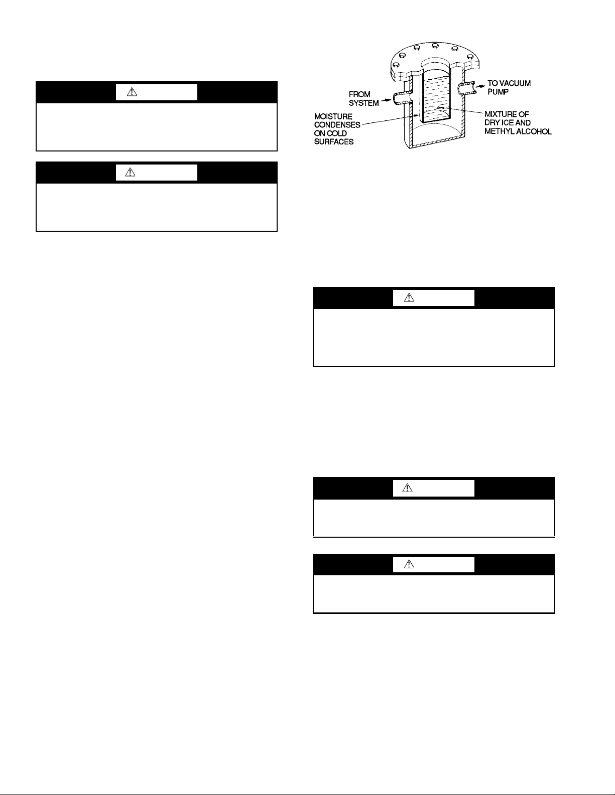
Chiller Dehydration — Dehydration is recommended if
Fig. 12 — Dehydration Cold Trap
the chiller has been open for a considerable period of time, if
the chiller is known to contain moisture, or if there has been a
complete loss of chiller holding charge or refrigerant pressure.
CAUTION
Do not start or megohm-test the compressor motor or oil
pump motor, even for a rotation check, if the chiller is
under dehydration vacuum. Insulation breakdown and
severe damage may result.
WARNING
Starters must be disconnected by an isolation switch before
placing the machine under a vacuum. To be safe, isolate
any starter before evacuating the chiller if you are not sure
if there are live leads to the hermetic motor.
Dehydration can be done at room temperatures. Using a
cold trap (Fig. 12) may substantially reduce the time required
to complete the dehydration. The higher the room temperature,
the faster dehydration takes place. At low room temperatures, a
very deep vacuum is required to boil off any moisture. If low
ambient temperatures are involved, contact a qualified service
representative for the dehydration techniques required.
Perform dehydration as follows:
1. Connect a high capacity vacuum pump (5 cfm [.002 m
or larger is recommended) to the refrigerant charging
valve (Fig. 2). Tubing from the pump to the chiller should
be as short in length and as large in diameter as possible to
provide least resistance to gas flow.
2. Use an absolute pressure manometer or a wet bulb vacuum indicator to measure the vacuum. Open the shutoff
valve to the vacuum indicator only when taking a reading. Leave the valve open for 3 minutes to allow the indicator vacuum to equalize with the chiller vacuum.
3. If the entire chiller is to be dehydrated, open all isolation
valves (if present).
4. With the chiller ambient tem perature at 60 F (15.6 C) or
higher, operate the vacuum pump until the manometer
reads 185 psig (1275 kPa), or a vacuum indicator reads
35 F (1.7 C). Operate the pump an additional 2 hours.
Do not apply a greater vacuum than 29.82 in. Hg vac
(757.4 mm Hg) or go below 33 F (0.56 C) on the wet bulb
vacuum indicator. At this temperature and pressure, isolated pockets of moisture can turn into ice. The slow rate
of evaporation (sublimation) of ice at these low temperatures and pressures greatly increases dehydration time.
5. Valve off the vacuum pump, stop the pump, and record
the instrument reading.
6. After a 2-hour wait, take another instrument reading. If
the reading has not changed, dehydration is complete. If
the reading indicates vacuum loss, repeat Steps 4 and 5.
7. If the reading continues to change after several attempts,
perform a leak test up to the maximum 160 psig
(1103 kPa) pressure. Locate and repair the leak, and repeat dehydration.
8. Once dehydration is complete, the evacuation process can
continue. The final vacuum prior to charging the unit with
refrigerant should in all cases be 29.9 in Hg (500 microns,
0.07 kPa [abs]) or less.
3
/s]
Inspect Water Piping — Refer to piping diagrams pro-
vided in the certified drawings and the piping instructions in
the 19XR Installation Instructions manual. Inspect the piping to
the cooler and condenser. Be sure that the flow directions are
correct and that all piping specifications have been met.
Piping systems must be properly vented with no stress on
waterbox nozzles and covers. Water flows through the cooler
and condenser must meet job requirements. Measure the pressure drop across the cooler and the condenser.
CAUTION
Water must be within design limits, clean, and treated to
ensure proper chiller performance and to reduce the potential of tube damage due to corrosion, scaling, or erosion.
Carrier assumes no responsibility for chiller damage resulting from untreated or improperly treated water.
Check Relief Valves — Be sure the relief valves have
been piped to the outdoors in compliance with the latest edition
of ANSI/ASHRAE Standard 15 and applicable local safety
codes. Piping connections must allow for access to the valve
mechanism for periodic inspection and leak testing.
The standard 19XR relief valves are set to relieve at
185 psig (1275 kPa) chiller design pressure.
Inspect Wiring
WARNING
Do not check the voltage supply without proper equipment
and precautions. Serious injury may result. Follow power
company recommendations.
CAUTION
Do not apply any kind of test voltage, even for a rotation
check, if the chiller is under a dehydration vacuum. Insulation breakdown and serious damage may result.
1. Examine the wiring for conformance to the job wiring diagrams and all applicable electrical codes.
2. Compare the ampere rating on the starter nameplate to
rating on the compressor nameplate. The overload trip
amps must be 108% to 120% of the rated load amps.
3. The starter for a centrifugal compressor motor must
contain the components and terminals required for PIC 5
controls platform. Check the certified drawings.
4. Check the voltage to the components and compare it to
the nameplate values.
5. Ensure that fused disconnects or circuit breakers have
been supplied for the control panel.
18
Page 19
6. Ensure all electrical equipment and controls are properly
grounded in accordance with job drawings, certified
drawings, and all applicable electrical codes.
7. Ensure the customer’s contractor has verified proper operation of the pumps, cooling tower fans, and associated
auxiliary equipment. This includes ensuring motors are
properly lubricated and have proper electrical supply and
proper rotation.
8. Test the chiller compressor motor and its power lead insulation resistance with an insulation tester such as a megohmmeter. (Use a tester rated for motor voltage.)
a. Open the starter main disconnect switch and follow
lockout/tagout rules.
CAUTION
Ensure the starter (with relay 1CR closed) goes through a
complete and proper start cycle.
SOLID-STATE STARTER
WARNING
This equipment is at line voltage when AC power is connected. Pressing the STOP button does not remove voltage.
CAUTION
An isolation switch or circuit breaker must be open ahead
of any solid-state starter when the chiller is in a vacuum. If
not, damage to the machine may result.
If the motor starter is a solid-state starter, the motor leads
must be disconnected from the starter before an insulation
test is performed. The voltage generated from the tester can
damage the starter solid-state components.
b. With the tester connected to the motor leads, take
10-second and 60-second megohm readings as
follows:
3-Lead Motor
and test between the group and ground.
c. Divide the 60-second resistance reading by the
10-second reading. The ratio, or polarization
index, must be one or higher. Both the 10 and
60-second readings must be at least 50 megohms.
If the readings on a field-installed starter are unsatisfactory, repeat the test at the motor with the
power leads disconnected. Satisfactory readings in
this second test indicate the fault is in the power
leads.
— Tie terminals 1, 2, and 3 together
Check Starter
WARNING
BE AWARE that certain automatic start arrangements can
engage the starter. Open the disconnect ahead of the starter
in addition to shutting off the chiller or pump. Failure to
follow this procedure may result in personal injury by electric shock.
Use the instruction and service manual supplied by the starter manufacturer to verify the starter has been installed correctly, to set up and calibrate the starter, and for complete troubleshooting information.
WARNING
The main disconnect on the starter front panel may not
deenergize all internal circuits. Open all internal and
remote disconnects before servicing the starter. Failure to
follow this procedure may result in personal injury by electric shock.
MECHANICAL STARTER
1. Check all field wiring connections for tightness, clearance from moving parts, and correct connection.
2. Check the contactor(s) to ensure they move freely. Check
all other electro-mechanical devices, such as relays, for
free movement. If the devices do not move freely, contact
the starter manufacturer for replacement components.
3. Reapply starter control power (not main chiller power) to
check the electrical functions.
1. Ensure all wiring connections are properly terminated to
the starter.
2. Verify the ground wire to the starter is installed properly
and is sufficient size.
3. Verify the motors are properly grounded to the starter.
4. Verify the proper ac input voltage is brought into the starter according to the certified drawings.
5. Apply power to the starter.
Oil Charge — The oil charge for the 19XR two-stage com-
pressor frame size 6 is 29 gal (110 L); for frame size 7 the oil
charge is 44.5 gal (168 L).
The chiller is shipped with oil in the compressor. When the
sump is full, the oil level should be no higher than the middle
of the upper sight glass, and minimum level is the bottom of
the lower sight glass (Fig. 2). If oil is added, it must meet Carrier’s specification for centrifugal compressor use as described in
the Oil Specification section on page 39. Charge the oil
through the oil charging valve located near the bottom of the
transmission housing. The oil must be pumped from the oil
container through the charging valve due to higher refrigerant
pressure. The pumping device must be able to lift from 0 to
200 psig (0 to 1380 kPa) or above unit pressure. Oil should
only be charged or removed when the chiller is shut down.
Power Up the Controls and Check the Oil
Heater —
sor and the chiller is not in a vacuum before energizing the controls. Typically a circuit breaker in the starter energizes the oil
heater and the control circuit.
The oil heater is energized by powering the control circuit.
This should be done several hours before start-up to minimize
oil-refrigerant migration. The oil heater is controlled by the
PIC 5 and is powered through a contactor in the control panel.
A separate circuit breaker powers the heater, oil pump, and the
control circuit. This arrangement allows the heater to energize
when the main motor circuit breaker is off for service work or
extended shutdowns.
Ensure that an oil level is visible in the compres-
Software Configuration
WARNING
Do not operate the chiller before the control configurations
have been checked and a Control Test has been satisfactorily completed. Protection by safety controls cannot be
assumed until all control configurations have been
confirmed.
See the 19XR with PIC 5 Controls Operation and Troubleshooting manual for instructions on using the PIC 5 interface to
configure the 19XR unit. As the unit is configured, all configuration settings should be written down. A log, such as the one
19
Page 20
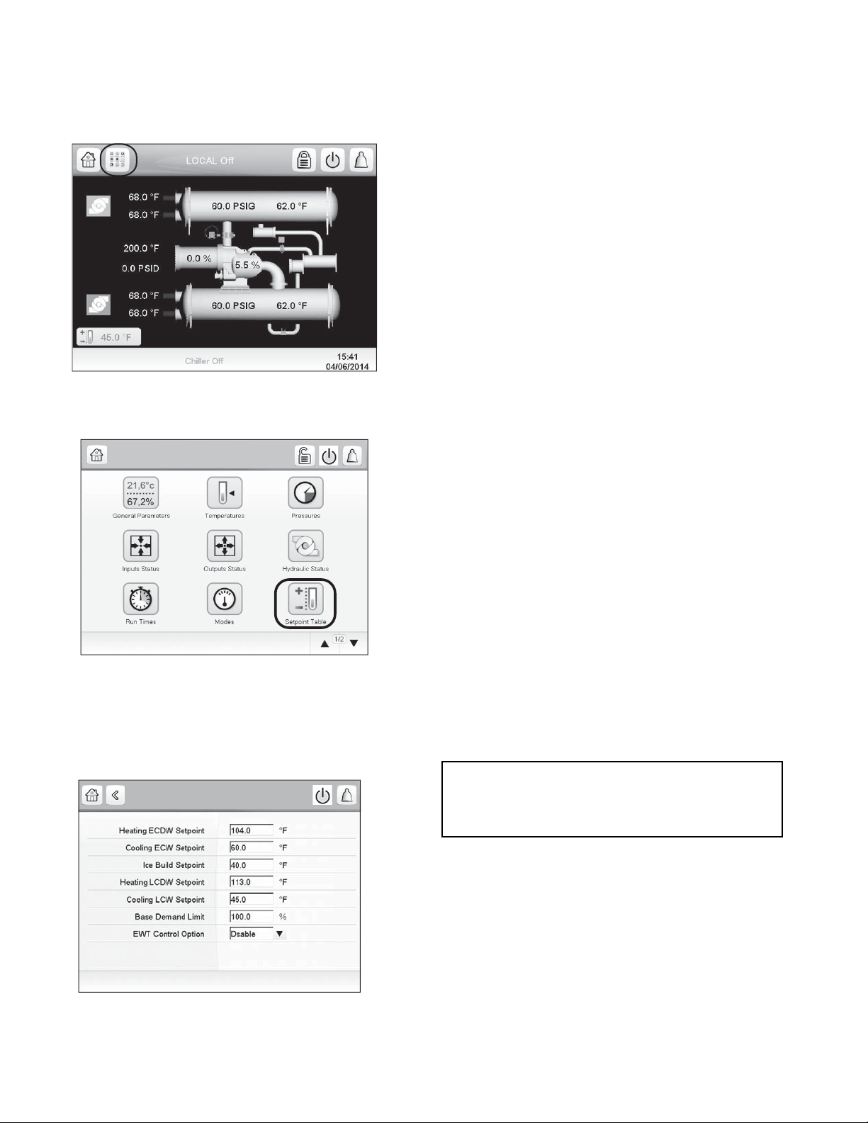
shown on pages CL-1 to CL-8, provides a list for configuration
Fig. 13 — Main Menu Icon
Fig. 14 — Main Menu — Setpoint Table Icon
a19-2121
SETPOINT - Setpoint Table
Fig. 15 — Setpoint Table Screen
values.
Input the Design Set Points — To access the set
point screen, press the Main Menu icon on the home screen.
See Fig. 13.
The Main Menu screen is displayed. Press the Setpoint Ta-
ble icon (Fig. 14).
Main Menu
The Setpoint screen is displayed (see Fig. 15). Set the base
demand limit set point, and either the LCW set point or the
ECW set point. To set a value, press the appropriate set point,
enter the value, and press OK. For more information, see the
the 19XR with PIC 5 Controls Operation and Troubleshooting
manual.
Input the Local Occupied Schedule — Access
the schedule screen and set up the occupied time schedule according to the customer’s requirements. If no schedule is available, the default is factory set for 24 hours occupied, 7 days per
week including holidays. The Schedule Menu as well as the
Holiday Menu can be reached through the Configuration Menu
(see Appendix A on page 88 for an overview of the available
menus). When the control mode is LOCAL SCHEDULE, the
chiller will be automatically started if the configured local
schedule is occupied; it will be shut down by the unoccupied
schedule, EMSTOP software point, STOP button on HMI
screen, or remote emergency stop contact.
The Network Schedule should be configured if a CCN system is being installed. When control mode is NETWORK, the
chiller can be started and stopped by the CHIL_S_S software
point as written by other equipment through the network command and network schedule. The chiller can be shut down by
EMSTOP software point and remote emergency stop contact.
For more information about setting time schedules, see the
19XR with PIC 5 Controls Operation and Troubleshooting
manual.
Input Service Configurations — For specific values
for the following configurations, refer to the chiller performance data or job-specific data sheet:
• password
• log in/logout
• input time and date
• service parameters
• equipment configuration
• automated control test
PASS W OR D — The PIC 5 control system provides different
levels of access: Basic access, User access, Advanced User/
Service access and Factory access. User access provides basic
access to the chiller controls. Advanced User access has access
to all Service tables, and Factory user has access to factory tables. The PIC 5 default password configurations are as follows:
• Basic: No password required
• User: 1111
• Advanced User / Service Access: 2222
• Factory: 4444
When accessing the SERVICE tables, a password must be
entered. The password can be changed from the Configuration
Menu. USER CONFIGURATION allows change of the User
access password. SERVICE PARAMETERS allows change of
the Advanced User/Service password, and FACTORY PARAMETERS allows change of the Factory password. Passwords must be from 1 to 5 digits (range from 1 to 65535).
IMPORTANT: Be sure to remember the password. Retain a
copy for future reference. Without the password, access to
the SERVICE menu will not be possible unless accessed by
a Carrier representative.
LOGIN/LOGOUT — Press the lock icon on the home screen
to enter the password. See Fig. 16.
20
Page 21
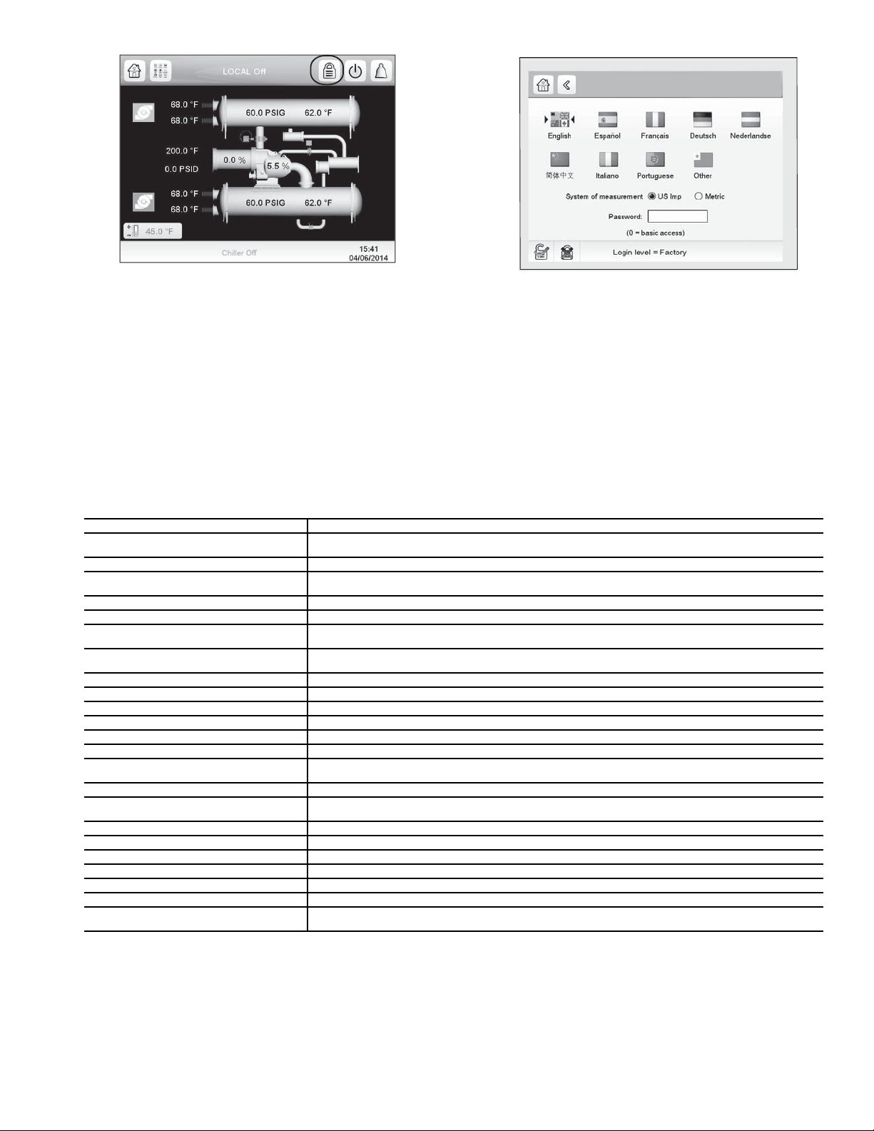
Fig. 16 — Lock Icon
User Login Screen
Fig. 17 — User Login Screen
The User Login Screen is displayed. Enter the password on
this screen. See Fig 17. The language and system of measurement can also be changed on this screen. For details, see the
19XR with PIC 5 Controls Operation and Troubleshooting
guide.
INPUT TIME AND DATE — Set day and time and if applicable Holidays through MAIN MENU CONFIGURATION
MENU DATE/TIME CONFIGURATION. See the Controls Operation and Troubleshooting guide for details. Because
a schedule is integral to the chiller control sequence, the chiller
will not start until the time and date have been set.
NOTE: The date format is MM-DD-YY for English units and
MODIFY CONTROLLER IDENTIFICATION IF NECESSARY — The module address can be changed from the Configuration Menu. Change this address under CONTROL
IDENTIFICATION for each chiller if there is more than one
chiller at the jobsite. Write the new address on the HMI module
for future reference.
CONFIGURE SERVICE TABLES — Access the SERVICE tables through MAIN MENU CONFIGURATION
MENU to modify or view the job site parameters shown in Table 7. For details, see the 19XR with PIC 5 Controls Operation
and Troubleshooting guide.
DD-MM-YY for SI units.
Table 7 — Job Site Parameters
PARAMETER TABLE
Starter Type
Motor Rated Line Voltage CONF_ISM — Motor rated voltage from chiller information nameplate.
Volt Transformer Ratio
Motor Rated Load Amps CONF_ISM — Per chiller nameplate data. RL AMPS on compressor nameplate.
Motor Locked Rotor Trip CONF_ISM — Per chiller iden tification nameplate.
Starter LRA Rating
Motor Current CT Ratio
Current % Imbalance CONF_ISM — Current imbalance trip threshold. Enter up to 100% for starter type 3 (VFD).
Ground Fault Current Transformers CONF_ISM — Ent er 0 if no ground fault CTs are wired to terminal J5 of ISM. Enter 1 if gr ound fault CTs are used.
Ground Fault CT Ratio CONF_ISM — Enter ratio (reduced to a ratio to 1) of ground fault CT.
Single Cycle Dropout CONF_ISM — ENABLE if motor protection required from drop in line voltage within one cycle.
Line Frequency CONF_ISM — Enter YES for 60 Hz or NO for 50 Hz.
Line Frequency Faulting CONF_ISM — ENABLE if motor protection required for drop in line frequency.
Hot Gas Bypass Option
Minimum Load Points (Tsmin, IGVmin) CFGSURGE — Per job data — See modify load points section. Refer to table located in the control panel.
Full (Maximum) Load Points (Tsmax, IGVmax)
Surge Line Shape Factor (shapefac) CFGSURGE — Per Chiller Requisition (shapefac). Refer to table located in the control panel.
Chilled Medium FACTORY — Enter water or brine.
Evaporator Refrigerant Trippoint CFGLIMIT — Usually 3° F (1.7° C) below design refrigerant temperature.
Evaporator Flow Delta P Cutout CFGLIMIT — Per Chiller Requisition if available or enter 50% of design pressure drop to 0.5 psi (3.4 kPa).*
Condenser Flow Delta P Cutout CFGLIMIT — Per Chiller Requisition if available or enter 50% of design pressure drop to 0.5 psi (3.4 kPa).*
High Condenser Water Delta P CFGLIMIT — Enter the maximum allowable value for condenser water pressure drop.
Motor Rated Kilowatts
*With variable flow systems this point may be configured to the lower end of
the range.
NOTE: Other parameters: Screens are normally left at the default settings;
they may be changed as required. The time and persistence settings on the
CONF_ISM table can be adjusted to increase or decrease the sensitivity to a
fault condition. Increasing time or persistence decreases sensitivity. Decreasing time or persistence increases sensitivity to the fault condition.
CONF_ISM — Select 0 for full voltage, 1 for reduced voltage, 2 for solid state, or 3 for freestanding variable
frequency drive.
CONF_ISM — Enter ratio (reduced to a ratio to 1) of power transformer wired to ter minal J3 of ISM. If no transf ormer
is used enter 1.
CONF_ISM — Enter value from nameplate in starter cabinet MAXIMUM FUSE. This value shall always be “9999” for
Benshaw RediStart MX3 wye-delta and solid-state starters.
CONF_ISM — Enter ratio (reduced to a ratio to 1) of current transf ormers wired to terminal J4 of ISM. This value shall
always be “100” for Benshaw RediStart MX3 and solid-state starters.
CONF_OPT — 1 = HGBP for Surge Correction; 2 = HGBP for Low Load Operation; 3 = Combination HGBP; 0 = no
HGBP or HGBP is Disabled.
CFGSURGE — Chiller Requisition (TSmin, IGV min) or per job data — See modify load points section. Refer to table
located in the control panel.
FACTORY — Enter value from chiller requisition form (product data submittal) if DEMAND LIMIT SOURCE is set to
kW.
21
Page 22
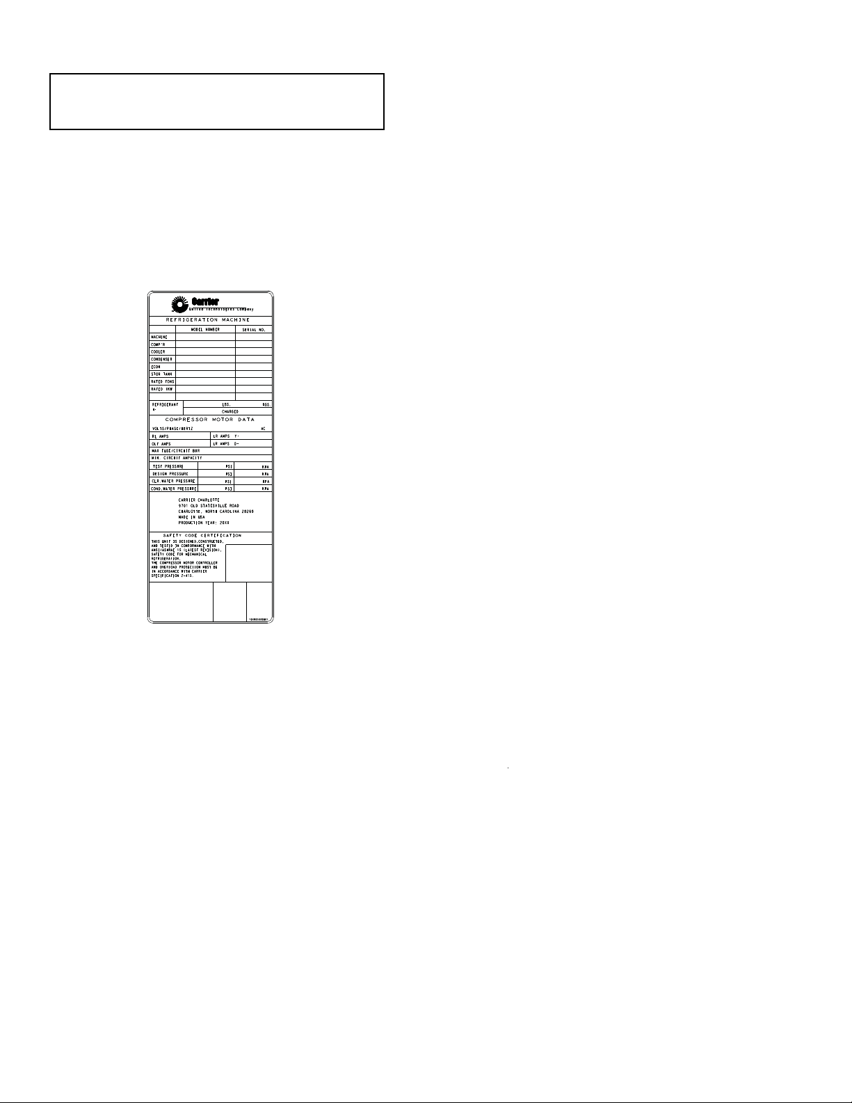
Field Set Up and Verification
SAFETY CODE CERTIFICATION
COMPRESSOR MOTOR DATA
R-
REFRIGERATION MACHINE
CARRIER CHARLOTTE
9701 OLD STATESVILLE ROAD
CHARLOTTE, NORTH CAROLINA 28269
MADE IN USA
PRODUCTION YEAR: 20XX
19XR05009801
A United Technologies Company
T
M
THIS UNIT IS DESIGNED,CONSTRUCTED,
AND TESTED IN CONFORMANCE WITH
ANSI/ASHRAE 15 (LATEST REVISION),
SPECIFICATION Z-415.
IN ACCORDANCE WITH CARRIER
AND OVERLOAD PROTECTION MUST BE
THE COMPRESSOR MOTOR CONTROLLER
REFRIGERATION.
SAFETY CODE FOR MECHANICAL
TEST PRESSURE
DESIGN PRESSURE
CLR.WATER PRESSURE
COND.WATER PRESSURE
PSI
PSI
PSI
PSI
KPA
KPA
KPA
KPA
CAZTREH/ESAHP/STLOV
RL AMPS
OLT AMPS
LR AMPS Y-
LR AMPS DMAX FUSE/CIRCUIT BKR
MIN. CIRCUIT AMPACITY
LBS.
CHARGED
KGS.REFRIGERANT
MODEL NUMBER
SERIAL NO.
MACHINE
COMP'R
COOLER
CONDENSER
ECON
STOR TANK
RATED iKW
RATED TONS
Fig. 18 — Machine Identification Nameplate
CHILLER ID NAMEPLATE — CONSTANT SPEED CHILLER
a19-1881
IMPORTANT: Some parameters are specific to the chiller
configuration and will need to be verified prior to operation.
All command functions must be initiated from the HMI.
Use the HMI touch screen to confirm that the ISM values
match the chiller paramter labels and Chiller Builder design
data sheet. The ISM values can be located from MAIN MENU
CONFIGURATION MENU ISM CONFIGURATION.
LABEL LOCATIONS — Verify the following labels have
been installed properly and match the chiller requisition:
• Surge Parameters — Located inside the chiller control
panel.
• Chiller identification nameplate — Located on the right
side of the control panel. (See Fig. 18.)
STARTER/DRIVE PROTECTION AND OTHER INCOMING WIRING
1. Verify that the branch disconnects or other local disconnects are open and properly tagged out.
2. Verify that the branch circuit protection and AC input
wiring to the starter are in accordance with NEC/CEC
(National Electrical Code/California Energy Commission) and all other local codes.
3. Verify that the fuses are per the field wiring diagram.
4. Verify that the incoming source does not exceed the
SCCR (short circuit current rating) of the equipment
marking.
5. Verify the power lugs in the starter/VFD and branch protection are properly secured. Inspect the ground cable and
ensure it is properly connected at the branch and to the
6. Verify the conduit for the power wiring in securely con-
ground lug in the starter.
nected to the starter flanged cover and runs continuously
to the branch protection.
7. Ensure the control and signal wires connected to the
chiller controller or the starter/VFD are in separate conduits.
FINE TUNING VPF (VARIABLE PRIMARY FLOW)
SURGE PRE VENTION — Figures 19-22 show how the parameters defined below will affect the configured surge line.
The menu can be found under MAIN MENU CONFIGU-
RATION MENU SURGE CORRECTION CONFIG.
NOTE: Before tuning surge prevention, check for VFD (variable frequency drive) speed limitation or capacity overrides. If
the source of low capacity is found in one of these places, do
not proceed with an attempt to tune the Surge Prevention configurations.
If capacity is not reached
and
1. ACTUAL GUIDE VANE POSITION < GUIDE VANE
TRAVEL RANGE
and
2. SURGE PREVENTION ACTIVE = YES (can be identified in MAIN MENU MAINTENANCE MENU
SURGE CORRECTION)
and
3. PERCENT LINE CURRENT < 100%
then the surge line is probably too conservative.
Note the following parameters from HMI when maximum
ACTUAL LINE CURRENT achieved:
• EVAPORATOR REFRIGERANT TEMP
• EVAPORATOR PRESSURE
• CONDENSER REFRIG TEMP
• CONDENSER PRESSURE
• ACTUAL GUIDE VANE POSITION
• ACTUAL LINE CURRENT
The ACTIVE DELTA Tsat and the CALC REF DELTA
TSAT can be monitored on the MAINTENANCE MENU
SURGE CORRECTION screen. When DELTA TSAT exceeds
CALC REF DELTA TSAT + ENVELOPE LINE OFFSET
surge prevention will occur.
If ACTUAL GUIDE VANE POSITION is less than 30%,
then increase SURGE DELTA TSMIN in steps of 2º F (1.2º C)
until one of the three conditions listed above no longer applies.
Do not change SURGE DELTA TSMAX.
If ACTUAL GUIDE VANE POSITION is greater than
60%, then increase SURGE DELTA TSMAX in steps of 2º F
(1.2º C) until cooling capacity is reached or one of conditions
listed above no longer applies. Do not change SURGE/HGBP
DELTA TSMIN.
If ACTUAL GUIDE VANE POSITION is more than 30%
AND less than 60%, then:
1. Increase SURGE DELTA TSMIN in steps of 2º F
(1.2º C).
2. Increase SURGE DELTA TSMAX in steps of 2º F
(1.2º C).
3. Repeat Steps 1 and 2 until one of the conditions listed
above no longer applies.
NOTE: DELTA TSMIN should seldom need to be increased
more than 10 degrees above the selection program value. Likewise, DELTA TSMAX rarely requires more than a 2º F
(1.2º C) increase.
If surge is encountered then the surge line is probably too
optimistic or high. Note following parameters from HMI at
surge:
• EVAPORATOR REFRIGERANT TEMP
• EVAPORATOR PRESSURE
• CONDENSER REFRIG TEMP
• CONDENSER PRESSURE
• ACTUAL GUIDE VANE POSITION
• AVERAGE LINE CURRENT
22
Page 23
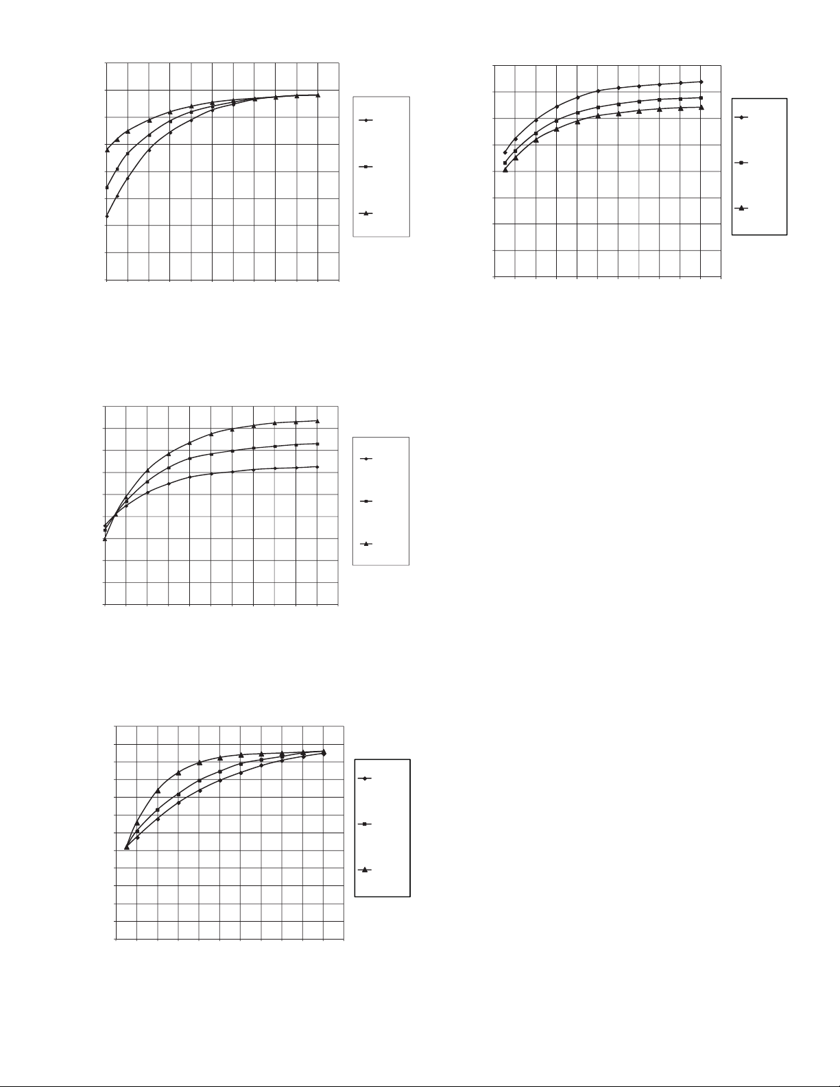
40
Fig. 19 — Effect of SURGE DELTA TSMIN on
Surge Prevention
a19-1959
0
5
10
15
20
25
30
35
40
45
0 102030405060708090100110
Tsmax= 60
Tsmax= 70
Tsmax= 80
GV_POS
Delta Tsat
Fig. 20 — Effect of SURGE DELTA TSMAX on
Surge Prevention
a19-1960
Fig. 21 — Effect of SURGE LINE SHAPE FACTOR
on Surge Prevention
a19-1961
0.00
5.00
10.00
15.00
20.00
25.00
30.00
35.00
40.00
0 102030405060708090100110
Speed Factor
=1.60
Speed Factor
=1.85
Speed Factor
=2.00
GV_POS
Delta Tsat
Fig. 22 — Effect of SURGE LINE SPEED FACTOR
on Surge Prevention
a19-1962
35
30
25
20
Delta Tsat
15
10
5
0
0 102030405060708090100110
60.00
55.00
50.00
45.00
40.00
35.00
30.00
Delta Tsat
25.00
20.00
15.00
10.00
5.00
0.00
0 10 20 30 40 50 60 70 80 90 100 110
GV_POS
GV_POS
Tsmin= 30
Tsmin= 40
Tsmin= 50
Shape factor
= -0.020
Shape factor
= -0.040
Shape factor
= -0.050
If ACTUAL GUIDE VANE POSITION is less than 30%,
go to Step 1. If ACTUAL GUIDE VANE POSITION is greater
than 60%, then go to Step 3.
1. Do not change SURGE LINE SHAPE FACTOR from
the value selected by Chiller Builder (ECAT). Decrease
SURGE DELTA TSMIN in 1° F steps up to 5 times.
Monitor chiller for surge.
2. If ACTUAL GUIDE VANE POSITION is still less than
30 and Step 1 failed, then increase the value of SURGE
LINE SHAPE FACTOR in steps of 0.01 up to 2 times.
For example, if surge is encountered when shape factor is
–0.06, increase the SURGE LINE SHAPE FACTOR to
–0.05. If this does not solve the problem, go to Step 5,
even if ACTUAL GUIDE VANE POSITION is less than
30%.
3. Do not change SURGE LINE SHAPE FACTOR from
the value selected by Chiller Builder (ECAT). Decrease
SURGE DELTA TSMAX by 1° F steps up to 5 times.
Monitor chiller for surge.
4. If ACTUAL GUIDE VANE POSITION is greater than
60% and Step 3 failed to eliminate surge, then set
SURGE DELTA TSMAX to 5° F below the value specified by Chiller Builder (ECAT). Increase the value of the
SURGE LINE SHAPE FACTOR in steps of 0.01 up to 2
times. For example, if surge is encountered when the
SURGE LINE SHAPE FACTOR is –0.06, increase the
SURGE LINE SHAPE FACTOR to –0.05. If this does
not solve the problem, go to Step 5, even if ACTUAL
GUIDE VANE POSITION is greater than 60%.
5. If ACTUAL GUIDE VANE POSITION is greater than
30% but less than 60% or if Step 2 failed (with ACTUAL
GUIDE VANE POSITION less than 30) or if Step 4
failed (with ACTUAL GUIDE VANE POSITION greater than 60), then perform this step. Do not change
SURGE LINE SHAPE FACTOR from the value specified by Chiller Builder (ECAT). Reset SURGE DELTA
TSMIN and SURGE DELTA TSMAX to the value specified by Chiller Builder (ECAT). Decrease SURGE DELTA TSMIN and SURGE DELTA TSMAX in steps of
1° F up to 5 times. Monitor chiller for surge.
If the chiller is equipped with a VFD and the drive does not
slow down adequately at part load, then the machine is likely
operating at a point above the configured “software” surge line
and the machine is in surge prevention mode. Check for a surge
protection message on the HMI. If the unit is not in a surge protection state, then the ENVELOPE SPEED FACTOR may
23
Page 24
need to be increased (more aggressive surge line protection) in
combination with a decrease in the SURGE LINE SHAPE
FACTOR.
MODIFY EQUIPMENT CONFIGURATION IF NECESSARY — The EQUIPMENT SERVICE table has screens to
select, view, or modify parameters. Carrier’s certified drawings
have the configuration values required for the jobsite. Modify
these values only if requested. Modifications can include:
• Chilled water reset
• Entering chilled water control (Enable/Disable)
• 4 to 20 mA demand limit
• Auto restart option (Enable/Disable)
• Remote contact option (Enable/Disable)
See the 19XR with PIC 5 Controls Operation and Trouble-
shooting guide for more details about these functions.
Perform a Controls Test (Quick Test) — Check
the safety controls status by performing an automated controls
test. The path to the QUICK TEST is MAIN MENU
QUICK TEST TABLE. (The QUICK TEST screen can only
be accessed when the chiller is in STOP mode.) On the
QUICK TEST table screen, select a test to be performed (see
Table 8).
The Quick Test checks all outputs and inputs for function.
In order to successfully proceed with the controls test, the compressor should be off, no alarms showing, and voltage should
be within ±10% of rating plate value. Each test asks the operator to confirm the operation is occurring and whether or not to
continue. If an error occurs, the operator can try to address the
problem as the test is being done or note the problem and proceed to the next test.
NOTE: If during the controls test the guide vanes do not open,
verify the low pressure alarm is not active. (An active low
pressure alarm causes the guide vanes to close.)
NOTE: The oil pump test will not energize the oil pump if
cooler pressure is below –5 psig (–35 kPa).
When the controls test is finished the test stops and the
QUICK TEST menu displays. If a specific automated test procedure is not completed, access the particular control test to test
the function when ready. For information about calibration, see
the sections Checking Pressure Transducers, page 46, and High
Altitude Locations, page 46.
Table 8 — Quick Test Table
CCN TABLE NAME: QCK_TEST
PIC 5 PATH: Main Menu Quick Test
LINE PIC 5 DESCRIPTION CCN NAME RANGE
1 Quick Test Enable QCK_TEST DSABLE/ENABLE DSABLE RW
2 GV 1 Calibration Enable GV1_CAL DSABLE/ENABLE DSABLE RW
3 GV1 Calibration Status
0=No Calibration or Failure
1=In Progress, 2=Completed
4 Guide Vane 1 Actual Ohms GV1_OHM 0.00 to 12000.00 RO
5 Guide Vane 1 Actual mA GV1_MAF 0.0 to 20.8 mA RO
6 Guide Vane 1 Forced Position Q_GV1POS 0.0 to 100.0 0.0 % RW
7 Quick Test GV1 Open Q_GV1OP OFF/ON OFF RW
8 Quick Test GV1 Close Q_GV1CL OFF/ON OFF RW
9 Quick Test Oil Pump Q_OILP OFF/ON OFF RW
10 Oil Pres Test Passed OP_PASS NO/YES RO
11 Oil Pump Delta Pressure OIL_PDQ –6.7 t o 420.0 psig RO
12 Quick Test Oil Heater Q_OILH OFF/ON OFF RW
13 Quick Test HGBP Open Q_HGBPOP OFF/ON OFF RW
14 Quick Test HGBP Close Q_HGBPCL OFF/ON OFF RW
15 Quick Test Damper Open Q_DMPOP OFF/ON OFF RW
16 Quick Test Damper Close Q_DMPCL OFF/ON OFF RW
17 Quick Test Cond Pump Q_CDWP OFF/ON OFF RW
18 Condenser Water Flow CDW_FLOW NO/YES RO
19 Quick Test Chilled Pump Q_CHWP OFF/ON OFF RW
20 Chileld Water Flow CHW_FLOW NO/YES RO
21 Condenser Water Flow CDW_FLOW NO/YES RO
22 Chilled Water Flow CHW_FLOW NO/YES RO
23 Quick Test Head Val Pos Q_HDP 0.0 to 100.0 0.0 % RW
24 Quick Test Diffuser Pos Q_SRD 0.0 to 100.0 0.0 % RW
25 Quick Test Chiller Status Q_CHST 4.0 to 20.0 4.0 mA RW
26 Quick Test Oil EXV Q_EXV 4.0 to 20.0 4.0 mA RW
27 Condenser Water Delta T CDW_DT –40.0 to 245.0 °F RO
28 Chilled Water Delta T CHW_DT –40.0 to 245.0 °F RO
29 Cond Water Deviation CDWT_DV OFF/ON RO
30 Chilled Water Deviation CHWT_DV OFF/ON RO
31 Quick Test Alarm Output Q_ALM OFF/ON OFF RW
32 Quick Test Alert Output Q_ALE OFF/ON OFF RW
33 Guide Vane 1 Ohms 100% GV1_MAXO 0.00 to 12000.00 RO
34 Guide Vane 1 Ohms 0% GV1_MINO 0.00 to 12000.00 RO
35 Guide Vane 1 mA 100% GV1_MAXA 0.0 to 20.8 mA RO
36 Guide Vane 1 mA 0% GV1_MINA 0.0 to 20.8 mA RO
LEGEND
GV — Guide Vane
HGBP — Hot Gas Bypass
RO — Read Onl y
RW — Read Write
*Default value is shown only if configurable in this table.
GV1_STAT 0 to 2 RO
NOTES:
1. Quick Test ENABLE defaults back to DISABLE after 1 hour.
2. During any of the tests, an out-of-range reading will have an asterisk (*)
next to the reading and a message will be displayed if the diffuser control
is enabled.
DEFAULT
VALUE*
UNIT READ/WRITE
24
Page 25
Charge Refrigerant into Chiller
CAUTION
The transfer, addition, or removal of refrigerant in spring
isolated chillers may place severe stress on and damage
external piping if springs have not been blocked in both up
and down directions.
CAUTION
Always operate the condenser and chilled water pumps
during charging operations to prevent freeze-ups.
1. Access the terminate lockout function on the PUMPDOWN/LOCKOUT screen (located in the Maintenance
Menu).
2. IMPORTANT: Turn on the chilled water and condenser
water pumps to prevent freezing.
3. Open valve 4 on the pumpout unit and open valves 1a and
1b on the chiller cooler and condenser, Fig. 23 and 24.
Slowly open valve 2 on the pumpout unit to equalize the
pressure. This process takes approximately 15 minutes.
4. Once the pressures have equalized, the discharge isolation valve, cooler isolation valve, optional hot gas bypass
isolation valve, and the refrigerant isolation valve can be
opened. Close valves 1a and 1b, and all pumpout unit
valves.
The standard 19XR chiller is shipped with the refrigerant
already charged in the vessels. However, the 19XR chiller may
be ordered with a nitrogen holding charge of 15 psig (103 kPa).
Evacuate the nitrogen from the entire chiller, and charge the
chiller from refrigerant cylinders.
CHILLER EQUALIZATION WITHOUT A PUMPOUT UNIT
CAUTION
When equalizing refrigerant pressure on the 19XR chiller
after service work or during the initial chiller start-up, do
not use the discharge isolation valve to equalize. A
charging hose (connected between the charging valves on
top of the cooler and condenser) should be used as the
equalization valve. Failure to follow this procedure may
damage equipment.
To equalize the pressure differential on a refrigerant isolated
19XR chiller, use the terminate lockout function of PUMPDOWN/LOCKOUT (located in the Maintenance Menu). This
helps to turn on pumps and advises the operator on proper procedures.
The following steps describe how to equalize refrigerant
pressure in an isolated 19XR chiller without a pumpout unit.
1. Access terminate lockout function on the Maintenance
Menu. (Alternatively, the Quick Test provides a means
for cooler and condenser pump control.)
2. IMPORTANT: Turn on the chilled water and condenser
water pumps to prevent freezing.
3. Slowly open the refrigerant charging valves. The chiller
cooler and condenser pressures will gradually equalize.
This process takes approximately 15 minutes.
4. Once the pressures have equalized, the cooler isolation
valve, the condenser isolation valve, and the hot gas isolation valve may now be opened. Refer to Fig. 23 and 24
for the location of the valves.
WARNING
Whenever turning the discharge isolation valve, be sure to
reattach the valve locking device. This prevents the valve
from opening or closing during service work or during
chiller operation. Failure to follow this procedure may
damage equipment and result in bodily injury.
CHILLER EQUALIZATION WITH FREE-STANDING
PUMPOUT UNIT — The following steps describe how to
equalize refrigerant pressure on an isolated 19XR chiller using
the pumpout unit.
WARNING
Whenever turning the discharge isolation valve, be sure to
reattach the valve locking device. This prevents the valve
from opening or closing during service work or during
chiller operation. Failure to follow this procedure may
damage equipment and result in bodily injury.
The full refrigerant charge on the 19XR chiller will vary
with chiller components and design conditions, as indicated on
the job data specifications. An approximate charge may be determined by adding the condenser charge to the cooler charge
as listed in the Heat Exchanger Data tables in the Physical Data
section that begins on page 48.
CAUTION
Always operate the condenser and chilled water pumps
whenever charging, transferring, or removing refrigerant
from the chiller. Always confirm that water flow is established. Failure to follow this procedure may result in equipment damage.
Use the PUMPDOWN/LOCKOUT terminate lockout function to monitor conditions and start the pumps.
If the chiller has been shipped with a holding charge
refrigerant is added through the pumpout charging connection
(Fig. 23 and 24, valve 1b). First evacuate the nitrogen holding
charge from the chiller vessels. Charge the refrigerant as a gas
until the system pressure exceeds 35 psig (241 kPa) for HFC134a. After the chiller is beyond this pressure the refrigerant
should be charged as a liquid until all the recommended refrigerant charge has been added. The charging valve (Fig. 23 and
24, valve 7) can be used to charge liquid to the cooler if the
cooler isolation valve (11) is present and is closed. Do not
charge liquid through the linear float to the condenser.
TRIMMING REFRIGERANT CHARGE — The 19XR
chiller is shipped with the correct charge for the design duty of
the chiller. Trimming the charge can best be accomplished
when the design load is available. To trim the charge, check the
temperature difference between the leaving chilled water temperature and cooler refrigerant temperature at full load design
conditions. If necessary, add or remove refrigerant to bring the
temperature difference to design conditions or minimum
differential. See the 19XR Installation Instructions manual for
required chiller refrigerant charge.
The 19XR chiller refrigerant charges are shown in Tables 9
and 10. Total refrigerant charge is the sum of the cooler, condenser, and economizer charge.
, the
25
Page 26
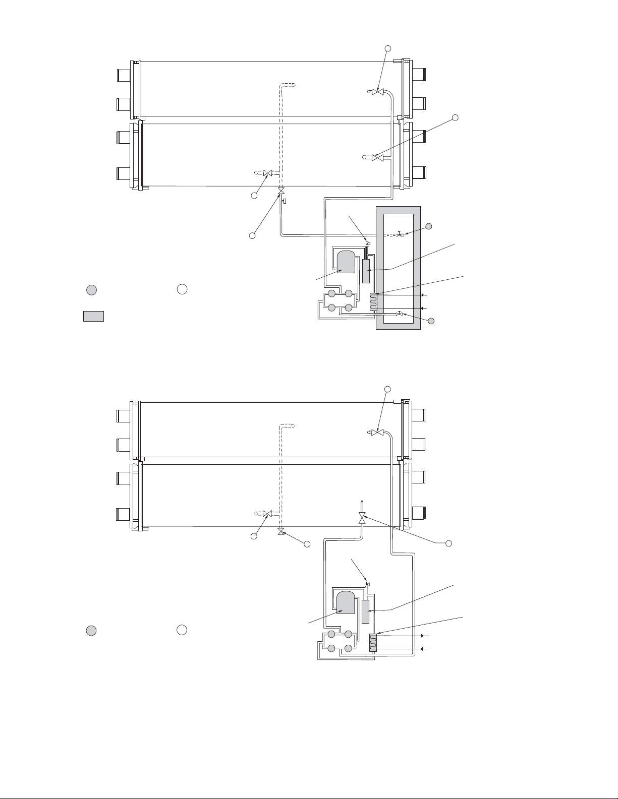
STORAGE
TANK LIQUID
VALVE
OIL
SEPARATOR
PUMPOUT
CONDENSER
WATER SUPPLY
AND RETURN
PUMPOUT
CONDENSER
STORAGE TANK
VAPOR VALVE
2
3
4
5
PRESSURE
RELIEF SAFETY
VALVE
PUMPOUT
COMPRESSOR
TEE FOR
CHARGING
REFRIGERANT
CHARGING VALVE
COOLER
REFRIGERANT
ISOLATION
VALVE
LIQUID LINE
SERVICE
VALVE
CHILLER
CONDENSER
VESSEL
CHILLER
COOLER
VESSEL
10
6
7
11
1a
1b
SERVICE VALVE ON
PUMPOUT UNIT
=
SERVICE VALVE ON
CHILLER (FIELD
SUPPLIED)
=
=
MAINTAIN AT LEAST 2 FT (610mm) CLEARANCE AROUND
STORAGE TANK FOR SERVICE AND OPERATION WORK.
REFRIGERANT
CHARGING VALVE
Fig. 23 — Typical Optional Pumpout System Piping Schematic with Storage Tank
a19-1721
OIL
SEPARATOR
PUMPOUT
CONDENSER
WATER SUPPLY
AND RETURN
PUMPOUT
CONDENSER
2
3
4
5
PRESSURE
RELIEF SAFETY
VALVE
PUMPOUT
COMPRESSOR
COOLER
REFRIGERANT
ISOLATION
VALVE
REFRIGERANT
CHARGING
VALVE
CHILLER
CONDENSER
VESSEL
CHILLER
COOLER
VESSEL
7
11
1a
1b
SERVICE VALVE ON
PUMPOUT UNIT
=
SERVICE VALVE ON
CHILLER
=
LIQUID LINE
SERVICE
VALVE
REFRIGERANT
CHARGING
VALVE
Fig. 24 — Typical Freestanding Pumpout System Piping Schematic without Storage Tan k
a19-1722
26
Page 27
Table 9 — 19XR Two-Stage Compressor Frame Size 6 Heat Exchanger Refrigerant Charge
ENGLISH SI
CODE*
COOLER ONLY CONDENSER ONLY ECONOMIZER ONLY COOLER ONLY CONDENSER ONLY ECONOMIZER ONLY
A40 1647 927 360 747 420 163
A41 1773 927 360 804 420 163
A42 1887 927 360 856 420 163
A45 1599 927 360 725 420 163
A46 1714 927 360 777 420 163
A47 1837 927 360 833 420 163
A60 1878 1074 360 852 48 7 163
A61 2022 1074 360 917 48 7 163
A62 2152 1074 360 976 48 7 163
A65 1823 1074 360 827 48 7 163
A66 1954 1074 360 886 48 7 163
A67 2095 1074 360 950 48 7 163
A4A 1681 861 360 762 391 163
A4B 1792 861 360 813 391 163
A4C 1897 861 360 860 391 163
A4F 1626 861 360 738 391 163
A4G 1736 861 360 787 391 163
A4H 1890 861 360 857 391 163
A6A 1917 998 360 870 453 163
A6B 2044 998 360 927 453 163
A6C 2164 998 360 982 453 163
A6F 1854 998 360 841 453 163
A6G 1979 998 360 898 453 163
A6H 2156 998 360 978 453 163
MACHINE CHARGE MACHINE CHARGE
REFRIGERANT WEIGHT (lb) REFRIGERANT WEIGHT (kg)
B40 — 1233 360 — 559 163
B41 — 1233 360 — 559 163
B42 — 1233 360 — 559 163
B45 — 1233 360 — 559 163
B46 — 1233 360 — 559 163
B47 — 1233 360 — 559 163
B60 — 1423 360 — 645 163
B61 — 1423 360 — 645 163
B62 — 1423 360 — 645 163
B65 — 1423 360 — 645 163
B66 — 1423 360 — 645 163
B67 — 1423 360 — 645 163
B4A — 1148 360 — 521 163
B4B — 1148 360 — 521 163
B4C — 1148 360 — 521 163
B4F — 1148 360 — 521 163
B4G — 1148 360 — 521 163
B4H — 1148 360 — 521 163
B6A — 1326 360 — 601 163
B6B — 1326 360 — 601 163
B6C — 1326 360 — 601 163
B6F — 1326 360 — 601 163
B6G
H — 1326 360 — 60
B6
*See Model Number Nomenclature on page 5.
— 1326 360 — 601 163
1 163
27
Page 28
Table 10 — 19XR Two-Stage Compressor Frame Size 7 Heat Exchanger Refrigerant Charge
ENGLISH SI
CODE*
COOLER ONLY CONDENSER ONLY ECONOMIZER ONLY COOLER ONLY CONDENSER ONLY ECONOMIZER ONLY
B60 2273 — 646 1031 — 293
B61 2355 — 646 1068 — 293
B62 2460 — 646 1116 — 293
B65 2185 — 646 991 — 293
B66 2275 — 646 1032 — 293
B67 2379 — 646 1079 — 293
B6A 2081 — 646 944 — 293
B6B 2162 — 646 981 — 293
B6C 2256 — 646 1023 — 293
B6F 1951 — 646 885 — 293
B6G 2019 — 646 916 — 293
B6H 2120 — 646 962 — 293
C60 2647 1610 646 1201 730 293
C61 2751 1610 646 1248 730 293
C62 2875 1610 646 1304 730 293
C65 2562 1610 646 1162 730 293
C66 2666 1610 646 1209 730 293
C67 2793 1610 646 1267 730 293
C6A 2443 1497 646 1108 679 293
C6B 2534 1497 646 1149 679 293
C6C 2627 1497 646 1192 679 293
C6F 2334 1497 646 1059 679 293
C6G 2415 1497 646 1095 679 293
C6H 2500 1497 646 1134 679 293
MACHINE CHARGE MACHINE CHARGE
REFRIGERANT WEIGHT (lb) REFRIGERANT WEIGHT (kg)
D60 — 2097 646 — 951 293
D61 — 2097 646 — 951 293
D62 — 2097 646 — 951 293
D65 — 2097 646 — 951 293
D66 — 2097 646 — 951 293
D67 — 2097 646 — 951 293
D6A — 1947 646 — 883 293
D6B — 1947 646 — 883 293
D6C — 1947 646 — 883 293
D6F — 1947 646 — 883 293
D6G — 1947 646 — 883 293
D6H — 1947 646 — 883 293
*See Model Number Nomenclature on page 5.
28
Page 29
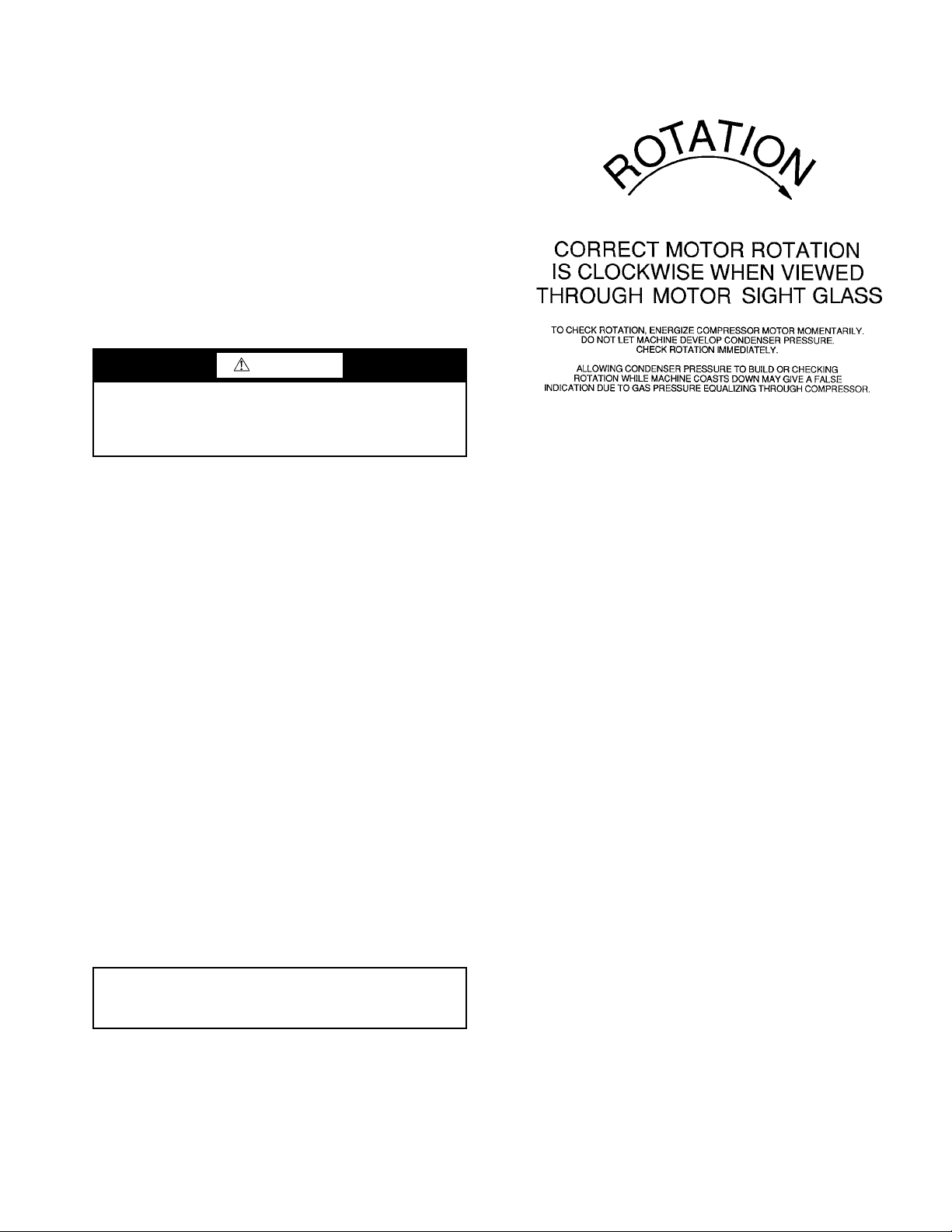
INITIAL START-UP
Fig. 25 — Correct Motor Rotation
Preparation —
1. Power is on to the main starter, oil pump relay, tower fan
starter, oil heater relay, and the chiller control panel.
2. Cooling tower water is at proper level and at-or-below
design entering temperature.
3. Chiller is charged with refrigerant and all refrigerant and
oil valves are in their proper operating positions.
4. Oil is at the proper level in the reservoir sight glasses.
5. Oil reservoir temperature is above 140 F (60 C) or above
CALC EVAP SAT TEMP plus 50 F (28 C).
6. Valves in the evaporator and condenser water circuits are
open.
NOTE: If the pumps are not automatic, ensure water is
circulating properly.
Before starting the chiller, verify:
CAUTION
Do not permit water or brine that is warmer than 110 F
(43 C) to flow through the cooler or condenser. Refrigerant
overpressure may discharge through the relief valves and
result in the loss of refrigerant charge.
7. Access the PUMPDOWN/LOCKOUT feature from the
Maintenance Menu. Press the End Lockout button on the
touch screen and accept the “press OK to Terminate
Lockout?” prompt. The unit is reset to operating mode.
The chiller is locked out at the factory in order to prevent
accidental start-up.
Check Motor Rotation
1. Disengage the main starter disconnect and engage the
control panel power circuit breaker.
NOTE: The circuit breaker may be located in the starter if
the disconnect and step down transformer option was ordered with the starter. If located in the starter, close the
door securely after this step.
2. Close the starter enclosure door.
3. The ISM (integrated starter module) mounted in the starter enclosure checks for proper phase rotation as soon as
power is applied to the starter and the PIC 5 controls
power up.
4. An alarm message will appear on the HMI screen if the
phase rotation is incorrect. If this occurs reverse any 2 of
the 3 incoming power leads to the starter and reapply
power. The motor is now ready for a rotation check.
5. Start the chiller by Local On (assumes LOCAL operation
mode) by pressing the Start/Stop button on the HMI and
following the prompts. The PIC 5 control performs startup checks.
6. When the starter is energized and the motor begins to
turn, check for clockwise motor rotation (Fig. 25).
IMPORTANT: Do not check motor rotation during coastdown. Rotation may have reversed during equalization of
vessel pressures.
Check Oil Pressure and Compressor Stop
1. When the motor is at full speed, note the differential oil
pressure reading on the HMI default screen. It should be
between 18 and 40 psid (124 and 206 kPad). The oil
pump will geenrate design oil pressure only with the correct electrical phasing of ABC.
2. Press the Stop button and listen for any unusual sounds
from the compressor as it coasts to a stop.
To Prevent Accidental Start-Up — A chiller STOP
override setting may be entered to prevent accidental start-up
during service or whenever necessary. From the Main Menu,
access the General Parameters Menu and use the down arrow
to reach Stop Override on the GENUNIT table. Change Stop
Override to Yes; then execute the command by touching the
lightning button. The message “ALM-276 Protective Limit Stop Override” will appear in the Home Screen message area.
To restart the chiller, access the same screen change the Stop
Override option to No.
Check Chiller Operating Condition — Check to
be sure that chiller temperatures, pressures, water flows, and
oil and refrigerant levels indicate the system is functioning
properly.
Instruct the Customer Operator — Ensure the op-
erator(s) understand all operating and maintenance procedures.
Point out the various chiller parts and explain their function as
part of the complete system.
COOL ER-CON DENSE R — High side float chamber, relief
valves, refrigerant charging valve, temperature sensor locations, pressure transducer locations, Schrader fittings, waterboxes and tubes, and vents and drains.
OPTIONAL PUMPOUT STORAGE TANK AND PUMPOUT SYSTEM — Transfer valves and pumpout system, refrigerant charging and pumpdown procedure, and relief devices.
MOTOR COMPRESSOR ASSEMBLY — Guide vane actuator, transmission, motor cooling system, oil cooling system,
temperature and pressure sensors, oil sight glasses, integral oil
pump, isolatable oil filter, extra oil and motor temperature sensors, synthetic oil, and compressor serviceability.
MOTOR COMPRESSOR LUBRICATION SYSTEM —
Oil pump, cooler filter, oil heater, oil charge and specification,
operating and shutdown oil level, temperature and pressure,
and oil charging connections.
ECONOMIZER — Float valve, drain valve, Schrader fitting,
damper valve.
CONTROL SYSTEM — CCN and LOCAL start, reset,
menu, softkey functions, HMI operation, occupancy schedule,
set points, safety controls, and auxiliary and optional controls.
AUXILIARY EQUIPMENT — Starters and disconnects,
separate electrical sources, pumps, and cooling tower.
DESCRIBE CHILLER CYCLES — Refrigerant, motor
cooling, lubrication, and oil reclaim.
29
Page 30

REVIEW MAINTENANCE — Scheduled, routine, and extended shutdowns, importance of a log sheet, importance of
water treatment and tube cleaning, and importance of maintaining a leak-free chiller.
SAFETY DEVICES AND PROCEDURES — Electrical
disconnects, relief device inspection, and handling refrigerant.
CHECK OPERATOR KNOWLEDGE — Start, stop, and
shutdown procedures, safety and operating controls, refrigerant
and oil charging, and job safety.
REVIEW THE START-UP, OPERATION, AND MAINTENANCE MANUAL.
OPERATING INSTRUCTIONS
Operator Duties
1. Become familiar with the chiller and related equipment
before operating the chiller.
2. Prepare the system for start-up, start and stop the chiller,
and place the system in a shutdown condition.
3. Maintain a log of operating conditions and document any
abnormal readings.
4. Inspect the equipment, make routine adjustments, and
perform a Control Test. Maintain the proper oil and refrigerant levels.
5. Protect the system from damage during shutdown periods.
6. Maintain the set point, time schedules, and other PIC
functions.
Prepare the Chiller for Start-Up — Follow the steps
described in the Initial Start-Up section, page 29.
To Start the Chiller
1. Start the water pumps, if they are not automatic.
2. Press the Start/Stop icon on the HMI home screen to start
the system. If the chiller is in the OCCUPIED mode and
the start timers have expired, the start sequence will start.
Follow the procedure described in the Start-Up/Shutdown/Recycle Sequence section, page 11.
Check the Running System — After the compres-
sor starts, the operator should monitor the display and observe
the parameters for normal operating conditions:
1. The oil reservoir temperature should be above 120 F
(49 C) during shutdown.
2. The bearing oil temperature accessed from the Temperatures menu should be 120 to 165 F (49 to 74 C) for compressors with rolling element bearings. If the bearing temperature reads more than 180 F (83 C) with the oil pump
running, stop the chiller and determine the cause of the
high temperature. Do not restart the chiller until corrected.
3. The oil level should be visible anywhere in one of the two
sight glasses. Foaming oil is acceptable as long as the oil
pressure and temperature are within limits.
4. The oil pressure should be between 18 and 40 psid (124
and 207 kPad) differential, as seen on the HMI Transmission Status screen. Typically the reading will be 18 to
35 psid (124 to 241 kPad) at initial start-up.
5. The moisture indicator sight glass on the ref rigerant motor cooling line should indicate refrigerant flow and a dry
condition.
6. The condenser pressure and temperature varies with the
chiller design conditions. Typically the pressure will
range between 60 and 135 psig (390 and 950 kPa) with a
corresponding temperature range of 60 to 105 F (15 to
41 C). The condenser entering water temperature should
be controlled below the specified design entering water
temperature to save on compressor kilowatt
requirements.
7. Cooler pressure and temperature also will vary with the
design conditions. Typical pressure range will be between
29.5 and 40.1 psig (203.4 and 276.4 kPa), with temperature ranging between 34 and 45 F (1.1 and 7.2 C).
8. The compressor may operate at full capacity for a short
time after the pulldown ramping has ended, even though
the building load is small. The active electrical demand
setting can be overridden to limit the compressor kW, or
the pulldown rate can be decreased to avoid a high
demand charge for the short period of high demand operation. Pulldown rate can be based on load rate or temperature rate and is accessed on the MAINTENANCE
MENU CAPACITY CONTROLS RAMP_DEM
(Ramping Demand Limit Value).
9. The economizer (if installed) has two sight glasses that
look into the float chamber. When the chiller is operating,
the top sight glass is empty and the bottom sight glass is
full.
To Stop the Chiller
The occupancy schedule starts and stops the chiller automatically once the time schedule is configured.
The unit can be stopped manually using the HMI by pressing the green Start/Stop icon . The Unit Start/Stop screen is
displayed. Press Confirm Stop. The compressor will then follow the normal shutdown sequence as described in the StartUp/Shutdown/Recycle Sequence section on page 11. The
chiller is now in the OFF control mode.
IMPORTANT: Do not attempt to stop the chiller by opening
an isolating knife switch. High intensity arcing may occur.
If the chiller is stopped by an alarm condition, do not restart
the chiller until the problem is diagnosed and corrected.
After Limited Shutdown — No special preparations
should be necessary. Follow the regular preliminary checks and
starting procedures.
Preparation for Extended Shutdown — The refrig-
erant should be transferred into the pumpout storage tank (if
supplied; see Pumpout and Refrigerant Transfer Procedures on
page 31) to reduce chiller pressure and the possibility of leaks.
Maintain a holding charge of 5 to 10 lb (2.27 to 4.5 kg) of refrigerant or nitrogen to prevent air from leaking into the chiller.
If freezing temperatures are likely to occur in the chiller area, drain the chilled water, condenser water, and the pumpout
condenser water circuits to avoid freeze-up. Keep the waterbox
drains open. It is recommended not to store the refrigerant in
the unit if below freezing temperatures are anticipated. A nitrogen holding charge is recommended in this case.
Leave the oil charge in the chiller with the oil heater and
controls energized to maintain the minimum oil reservoir
temperature.
After Extended Shutdown — Ensure the water sys-
tem drains are closed. It may be advisable to flush the water
circuits to remove any soft rust that may have formed. This is a
good time to brush the tubes and inspect the Schrader fittings
on the waterside flow devices for fouling, if necessary.
Check the cooler pressure on the HMI panel and compare it
to the original holding charge that was left in the chiller. If (after adjusting for ambient temperature changes) any loss in pressure is indicated, check for refrigerant leaks. See Check Chiller
Tightness section, page 13.
Recharge the chiller by transferring refrigerant from the
pumpout storage tank (if supplied). Follow the Pumpout and
Refrigerant Transfer Procedures section on page 31. Observe
freeze-up precautions.
30
Page 31

Carefully make all regular preliminary and running system
checks. If the compressor oil level appears abnormally high,
the oil may have absorbed refrigerant. Ensure that the oil temperature is above 40 F (4.4 C) or above the EVAP SAT TEMP
plus 50 F (27 C).
Cold Weather Operation — When the entering con-
denser water temperature drops very low, the operator should
automatically cycle the cooling tower fans off to keep the temperature up. Piping may also be arranged to bypass the cooling
tower.
IMPORTANT: A field-supplied water temperature control system for condenser water should be installed.
The system should maintain the leaving condenser
water temperature at a temperature that is at least 20 F
(11C) above the leaving chilled water temperature.
Manual Guide Vane Operation — It is possible to
manually operate the guide vanes in order to check control
operation or to control the guide vanes in an emergency. Manual operation is possible by overriding the target guide vane
position.
NOTE: Manual control overrides the configured pulldown rate
during start-up and permits the guide vanes to open at a faster
rate. Motor current above the electrical demand setting, capacity overrides, and chilled water temperature below the control
point override the manual target and close the guide vanes. For
descriptions of capacity overrides and set points, see the 19XR
with PIC 5 Controls Operation and Troubleshooting guide.
Refrigeration Log — A refrigeration log (as shown in
Fig. 26), is a convenient checklist for routine inspection and
maintenance and provides a continuous record of chiller performance. It is also an aid when scheduling routine maintenance and diagnosing chiller problems.
Keep a record of the chiller pressures, temperatures, and liquid levels on a sheet similar to the one in Fig. 26. Automatic recording of data is possible by using CCN devices such as the
Data Collection module and a Building Supervisor. Contact a
Carrier representative for more information.
PUMPOUT AND REFRIGERANT
TRANSFER PROCEDURES
Preparation —
with an optional pumpout storage tank, pumpout system, or
pumpout compressor. The refrigerant can be pumped for service work to either the chiller compressor vessel or chiller condenser vessel by using the optional pumpout system. If a
pumpout storage tank is supplied, the refrigerant can be isolated in the storage tank. The following procedures describe
how to transfer refrigerant from vessel to vessel and perform
chiller evacuation.
The 19XR chiller may come equipped
CAUTION
The power to the pumpout compressor oil heater must be
on whenever any valve connecting the pumpout compressor to the chiller or storage tank is open. Leaving the heater
off will result in oil dilution by refrigerant and can lead to
compressor failure.
If the compressor is found with the heater off and a
valve open, the heater must be on for at least 4 hours to
drive the refrigerant from the oil. When heating the oil the
compressor suction must be open to a vessel to give the refrigerant a means to leave the compressor.
CAUTION
Always run the chiller cooler and condenser water pumps
and always charge or transfer refrigerant as a gas when the
chiller pressure is less than 35 psig (241 kPa). Below these
pressures, liquid refrigerant flashes into gas, resulting in
extremely low temperatures in the cooler/condenser tubes
and possibly causing tube freeze-up.
31
Page 32

REFRIGERATION LOG CARRIER 19XR SEMI-HERMETIC CENTRIFUGAL REFRIGERATION MACHINE
PLANT___________________________ MACHINE MODEL NO. ________________________ MACHINE SERIAL NO. _____________________________
32
DATE
TIME
__
REFRIGERANT FLOW TEMP. REFRIGERANT FLOW TEMP. REFRIG. BEARING TEMPS. OIL MOTOR
PRESS. TEMP. GPM IN OUT PRESS. TEMP. GPM IN OUT PRESS.
COOLER CONDENSER ECON.
#1 LSME#2 LSCE#3 HSME#4 HSCEPRESS.
COMPRESSOR
DIFF.
SUMP
TEMP
LEVEL
FLA/AMPS
POSITION)
(OR VANE
OPER-
ATOR
INITIALS
REMARKS
REMARKS: Indicate shutdowns on safety controls, repairs made and oil or refrigerant added or removed. Include amounts.
Fig. 26 — Refrigeration Log
Page 33

DANGER
COMPRESSOR
OIL
SEPARATOR
CONDENSER
LEAVING
WATER
ENTERING
WATER
VALVE
5
VALVE
4
VALVE
2
CONTROL
PANEL
FRAME
ASSEMBLY
OIL
HEATER
VALVE
3
OIL FILL
FITTING
Fig. 27 — Pumpout Unit
a23-1546
2 OL
2 OL
2 OL
MTR-1
L1
L2
PUMP OUT
COMPRESSOR
CRANKCASE HEATER
240-600v
27-40 WA TT
GND
H1 H4
X1 X2
X2
HIGH PRESSURE
SAFETY
NC OPEN > 185psig
CONTROL POWER
TRANSFORMER
XFMR-1
69 VA
C
C
C
8
7
HTR-1
FU1
0.25A
FU2
0.25A
FU3
0.5A
1 2
2
2
3
4
SS-1
OFF
AUTO ON
LOW PRESSURE CONTROL
NC OPEN < 7 psia (-15.7 in. HG)
CLOSE > 9 psia (-11.6 in. HG)
5
C
X2
6
FIELD
POWER
SUPPLY
L1
L2
L3
Fig. 28 — Pumpout Unit Wiring Schematic
a23-1615
LEGEND
C—Contactor
FU — Fuse
GND — Ground
HTR — Heater
MTR — Motor
NC — Normally Closed
OL — Overload
SS — Selector Switch
During transfer of refrigerant into and out of the optional
storage tank, carefully monitor the storage tank level gage.
Do not fill the tank more than 90% of capacity to allow for
refrigerant expansion. Overfilling may result in damage to
the tank or the release of refrigerant which will result in
personal injury or death.
CAUTION
Do not mix refrigerants from chillers that use different
compressor oils. Compressor damage can result.
Operating the Optional Pumpout Unit
(Fig. 27) —
pressor sight glass under all operating conditions and during
shutdown. If oil is low, add oil as described under Optional
Pumpout System Maintenance section, page 41. The pumpout
unit control wiring schematic is detailed in Fig. 28.
TO READ REFRIGERANT PRESSURES (during pumpout
or leak testing):
1. The display on the chiller control panel is suitable for determining refrigerant-side pressures and low (soft) vacuum. To assure the desired range and accuracy when measuring evacuation and dehydration, use a quality vacuum
indicator or manometer. This can be placed on the
Schrader connections on each vessel by removing the
pressure transducer (Fig. 2).
2. To determine pumpout storage tank pressure, a 30 in. Hg
vacuum -0-400 psi (-101-0-2769 kPa) gage is attached to
the storage tank.
3. Refer to Fig. 23 and 24 for valve locations and numbers.
Oil should be visible in the pumpout unit com-
POSITIVE PRESSURE CHILLERS WITH STORAGE
TANKS — In the Valve/Condition tables that accompany these
instructions, the letter “C” indicates a closed valve. Figures 23
and 24 show the locations of the valves.
CAUTION
Always run chiller cooler and condenser water pumps and
always charge or transfer refrigerant as a gas when chiller
vessel pressure is less than 35 psig (241 kPa). Below these
pressures, liquid refrigerant flashes into gas, resulting in
extremely low temperatures in the cooler/condenser tubes
and possibly causing tube freeze-up.
CAUTION
Transfer, addition, or removal of refrigerant in springisolated chillers may place severe stress on and damage
external piping if springs have not been blocked in both up
and down directions.
33
Page 34

Transfer Refrigerant from Pumpout Storage Tank to Chiller
WARNING
During transfer of refrigerant into and out of the 19XR
storage tank, carefully monitor the storage tank level gage.
Do not fill the tank more than 90% of capacity to allow for
refrigerant expansion. Overfilling may result in damage to
the tank and personal injury.
1. Equalize refrigerant pressure.
a. Turn on chiller water pumps and monitor chiller
pressures.
b. Close pumpout and storage tank valves 2 , 4, 5, and
10, and close refrigerant charging valve 7; open
chiller isolation valve 11 and any other chiller
isolation valves, if present.
c. Open pumpout and storage tank valves 3 and 6;
open chiller valves 1a and 1b.
VALVE 1A1B2345671011
CONDITION C C C C C
d. Gradually crack open valve 5 to increase chiller
pressure to 35 psig (241 kPa). Slowly feed refrigerant to prevent freeze-up.
e. Open valve 5 fully after the chiller pressure rises
above the freezing point of the refrigerant. Let the
storage tank and chiller pressure equalize. Open
refrigerant charging valve 7 and storage tank
charging valve 10 to let liquid refrigerant drain into
the chiller.
VALVE 1A1B2345671011
CONDITION C C
2. Transfer remaining refrigerant.
a. Close valve 5 and open valve 4. Turn off the
pumpout condenser water, and turn on the
pumpout compressor in manual mode to push
liquid refrigerant out of the storage tank. Monitor
the storage tank level until the tank is empty.
b. Close refrigerant charging valves 7 and 10.
c. Turn off the pumpout compressor.
d. Turn off the chiller water pumps.
e. Close valves 3 and 4.
f. Open valves 2 and 5.
VALVE 1A1B2345671011
CONDITION C C C C
g. Turn on pumpout condenser water.
h. Run the pumpout compressor in manual mode until
the storage tank pressure reaches 5 psig (34 kPa),
18 in. Hg vacuum (41 kPa absolute).
i. Turn off the pumpout compressor.
j. Close valves 1a, 1b, 2, 5, and 6.
VALVE 1A1B2345671011
CONDITIONCCCCCCCCC
k. Turn off pumpout condenser water.
Transfer the Refrigerant from Chiller to Pumpout Storage
Tank
1. Equalize refrigerant pressure.
a. Valve positions:
VALVE 1A1B2345671011
CONDITION C C C C C
b. Slowly open valve 5 and refrigerant charging
valves 7 and 10 to allow liquid refrigerant to drain
by gravity into the storage tank.
VALVE 1A1B2345671011
CONDITION C C
2. Transfer the remaining liquid.
a. Turn off pumpout condenser water. Place valves in
the following positions:
VALVE 1A1B2345671011
CONDITION C C
b. Run the pumpout compressor in automatic mode
until vacuum switch is satisfied and compressor
stops. Close valves 7 and 10.
VALVE 1A1B2345671011
CONDITION C C C C
c. Turn off the pumpout compressor.
3. Remove any remaining refrigerant.
a. Turn on chiller water pumps.
b. Turn on pumpout condenser water.
c. Place valves in the following positions:
VALVE 1A1B2345671011
CONDITION C C C C
d. Run the pumpout compressor until the chiller pres-
sure reaches 35 psig (241 kPa); then, shut off the
pumpout compressor. Warm chiller condenser
water will boil off any entrapped liquid refrigerant
and chiller pressure will rise.
e. When chiller pressure rises to 40 psig (276 kPa),
turn on the pumpout compressor until the pressure
again reaches 35 psig (241 kPa), then, turn off the
pumpout compressor. Repeat this process until the
chiller pressure no longer rises; then, turn on the
pumpout compressor and pump out until the chiller
pressure reaches 18 in. Hg vacuum (41 kPa absolute). This can be done in On or Automatic mode.
f. Close valves 1a, 1b, 3, 4, and 6.
VALVE 1A1B2345671011
CONDITIONCCCCCCCCC
g. Turn off the pumpout condenser water.
4. Establish vacuum for service. To conserve refrigerant,
operate the pumpout compressor as described in Step 3e
until the chiller pressure is reduced to 18 in. Hg
vacuum (41 kPa absolute).
This operation can be done in Automatic or On mode.
In Automatic mode, the compressor will stop automatically at approximately 15 in. Hg vacuum (51 kPa
absolute).
CHILLERS WITH ISOLATION VALVES — The va l v es referred to in the following instructions are shown in Fig. 23 and
24. Valve 7 remains closed.
Transfer All Refrigerant to Chiller Condenser Vessel
1. Push refrigerant into chiller condenser vessel.
a. Turn on the chiller water pumps and monitor the
chiller pressure.
b. Valve positions:
VALVE 1A1B234511
CONDITION C C
34
Page 35

c. Equalize the refrigerant in the chiller cooler and
condenser.
d. Turn off chiller water pumps and pumpout con-
denser water supply.
e. Turn on pumpout compressor to push liqu id out of
the chiller cooler vessel.
f. When all liquid has been pushed into the chiller
condenser vessel, close the cooler refrigerant isola-
tion valve (11).
g. Turn on the chiller water pumps.
h. Turn off the pumpout compressor.
2. Evacuate gas from chiller cooler vessel.
a. Close liquid line service valves 2 and 5; open
valves 3 and 4.
VALVE 1A1B234511
CONDITION C C C
b. Turn on pumpout condenser water.
c. Run pumpout compressor until the chiller cooler
vessel pressure reaches 18 in. Hg vacuum (41 kPa
absolute). Monitor pressures on the chiller control
panel and on refrigerant gages.
This operation can be done in Automatic or On
mode. In Automatic mode, the compressor will
stop automatically at approximately 15 in. Hg
vacuum (51 kPa absolute).
d. Close valve 1a.
e. Turn off pumpout compressor.
f. Close valves 1b, 3, and 4.
VALVE 1A1B234511
CONDITION CCCCCCC
g. Turn off pumpout condenser water.
h. Turn off chiller water pumps and lock out chiller
compressor.
Transfer All Refrigerant to Chiller Cooler Vessel
1. Push refrigerant into the chiller cooler vessel.
a. Turn on the chiller water pumps and monitor the
chiller pressure.
b. Valve positions:
VALVE 1A1B234511
CONDITION C C
c. Equalize the refrigerant in the chiller cooler and
condenser.
d. Turn off chiller water pumps and pumpout con-
denser water.
e. Turn on pumpout compressor to push refrigerant
out of the chiller condenser.
f. When all liquid is out of the chiller condenser,
close valve 11 and any other liquid isolation valves
on the chiller.
g. Turn off the pumpout compressor.
2. Evacuate gas from chiller condenser vessel.
a. Turn on chiller water pumps.
b. Make sure that liquid line servi ce valves 3 and 4
are closed and valves 2 and 5 are open.
VALVE 1A1B234511
CONDITION C C C
c. Turn on pumpout condenser water.
d. Run the pumpout compressor until t he chiller con-
denser reaches 18 in. Hg vacuum (41 kPa absolute)
in Manual or Automatic mode. Monitor pressure at
the chiller control panel and refrigerant gages.
e. Close valve 1b.
f. Turn off pumpout compressor.
g. Close valves 1a, 2, and 5.
VALVE 1A1B234511
CONDITION CCCCCCC
h. Turn off pumpout condenser water.
i. Turn o ff chiller water pumps and lock out chiller
compressor.
Return Refrigerant to Normal Operating Conditions
1. Be sure that the chiller vessel that was opened has been
evacuated.
2. Turn on chiller water pumps.
3. Open valves 1a, 1b, and 3.
VALVE 1A1B234511
CONDITION C C C C
4. Crack open valve 5, gradually increasing pressure in the
evacuated chiller vessel to 35 psig (241 kPa). Feed refrigerant slowly to prevent tube freeze-up.
5. Leak test to ensure chiller vessel integrity.
6. Open valve 5 fully.
VALVE 1A1B234511
CONDITION C C C
7. Close valves 1a, 1b, 3, and 5.
8. Open chiller isolation valve 11 and any other isolation
valves, if present.
VALVE 1A1B234511
CONDITION CCCCCC
9. Turn off chiller water pumps.
DISTILLING THE REFRIGERANT
1. Transfer the refrigerant from the chiller to the pumpout
storage tank as described in the Transfer the Refrigerant
from Chiller to Pumpout Storage Tank section on
page 34.
2. Equalize the refrigerant pressure.
a. Turn on chiller water pumps and monitor chiller
pressures.
b. Close pumpout and storage tank valves 2, 4, 5, and
10, and close chiller charging valve 7; open chiller
isolation valve 11 and any other chiller isolation
valves, if present.
c. Open pumpout and storage tank valves 3 and 6;
open chiller valves 1a and 1b.
VALVE 1A1B2345671011
CONDITION C C C C C
d. Gradually crack open valve 5 to increase chiller
pressure to 35 psig (241 kPa). Slowly feed refrigerant to prevent freeze-up.
e. Open valve 5 fully after the chiller pressure rises
above the freezing point of the refrigerant. Let the
storage tank and chiller pressure equalize.
35
Page 36

3. Transfer remaining refrigerant.
a. Close valve 3.
b. Open valve 2.
VALVE 1A1B2345671011
CONDITION C C C C
c. Turn on pumpout condenser water.
d. Run the pumpout compressor until the storage tank
pressure reaches 5 psig (34 kPa), 18 in. Hg vacuum
(41 kPa absolute) in Manual or Automatic mode.
e. Turn off the pumpout compressor.
f. Close valves 1a, 1b, 2, 5, and 6.
g. Turn off pumpout condenser water.
VALVE 1A1B2345671011
CONDITIONCCCCCCCCC
4. Drain the contaminants from the bottom of the storage
tank into a container. Dispose of contaminants safely.
GENERAL MAINTENANCE
Refrigerant Properties —
the 19XR chiller is HFC-134a. At normal atmospheric pressure, HFC-134a will boil at –14 F (–25 C) and must, therefore,
be kept in pressurized containers or storage tanks. The refrigerant is practically odorless when mixed with air and is noncombustible at atmospheric pressure. Read the Material Safety
Data Sheet and the latest ASHRAE Safety Guide for Mechanical Refrigeration to learn more about safe handling of this
refrigerant.
The standard refrigerant for
DANGER
HFC-134a will dissolve oil and some nonmetallic materials, dry the skin, and, in heavy concentrations, may displace enough oxygen to cause asphyxiation. When
handling this refrigerant, protect the hands and eyes and
avoid breathing fumes.
Adding Refrigerant — Follow the procedures de-
scribed in Trim Refrigerant Charge section, page 38.
CAUTION
Always use the compressor pumpdown function in the
PUMPDOWN/LOCKOUT feature to turn on the cooler
pump and lock out the compressor when transferring
refrigerant. Liquid refrigerant may flash into a gas and
cause possible freeze-up when the chiller pressure is below
30 psig (207 kPa) for HFC-134a.
Adjusting the Refrigerant Charge — If the addi-
tion or removal of refrigerant is required to improve chiller performance, follow the procedures given under the Trim Refrigerant Charge section, page 38.
Refrigerant Leak Testing — Because HFC-134a is
above atmospheric pressure at room temperature, leak testing
can be performed with refrigerant in the chiller. Use an electronic halogen leak detector, soap bubble solution, or ultrasonic
leak detector. Ensure that the room is well ventilated and free
from concentration of refrigerant to keep false readings to a
minimum. Before making any necessary repairs to a leak,
transfer all refrigerant from the leaking vessel.
Leak Rate — It is recommended by ASHRAE that chillers
be taken off line immediately and repaired if the refrigerant
leak rate for the entire chiller is more than 10% of the operating
refrigerant charge per year.
In addition, Carrier recommends that leaks totalling less
than the above rate but more than a rate of 0.1% of the total
charge per year should be repaired during annual maintenance
or whenever the refrigerant is transferred for other service
work.
Test After Service, Repair, or Major Leak —
If all the refrigerant has been lost or if the chiller has been
opened for service, the chiller or the affected vessels must be
pressure tested and leak tested. Refer to the Leak Test Chiller
section on page 16 to perform a leak test.
WARNING
HFC-134a should not be mixed with air or oxygen and
pressurized for leak testing. In general, this refrigerant
should not be present with high concentrations of air or
oxygen above atmospheric pressures, because the mixture
can undergo combustion.
TESTING WITH REFRIGERANT TRACER — Use an environmentally acceptable refrigerant as a tracer for leak test
procedures. Use dry nitrogen to raise the machine pressure to
leak testing levels.
TESTING WITHOUT REFRIGERANT TRACER — Another method of leak testing is to pressurize with nitrogen only
and to use a soap bubble solution or an ultrasonic leak detector
to determine if leaks are present.
TO PRESSURIZE WITH DRY NITROGEN
NOTE: Pressurizing with dry nitrogen for leak testing should
not be done if the full refrigerant charge is in the vessel
because purging the nitrogen is very difficult.
1. Connect a copper tube from the pressure regulator on the
cylinder to the refrigerant charging valve. Never apply
full cylinder pressure to the pressurizing line. Follow the
listed sequence.
2. Open the charging valve fully.
3. Slowly open the cylinder regulating valve.
4. Observe the pressure gage on the chiller and close the
regulating valve when the pressure reaches test level. Do
not exceed 140 psig (965 kPa).
5. Close the charging valve on the chiller. Remove the copper tube if it is no longer required.
Repair the Leak, Retest, and Apply Standing
Vacuum Test —
leaks with an electronic halide leak detector, soap bubble solution, or an ultrasonic leak detector. Bring the chiller back to atmospheric pressure, repair any leaks found, and retest.
After retesting and finding no leaks, apply a standing vacuum test. Then dehydrate the chiller. Refer to the Standing Vacuum Test and Chiller Dehydration sections (pages 16 and 18) in
the Before Initial Start-Up section.
After pressurizing the chiller, test for
Checking Guide Vanes — During normal shutdown,
when the chiller is off, the guide vanes are closed. Check that
the coupling is tight on the shaft and make sure that the guide
vane shaft is closed. Complete the following steps to adjust position (see Fig. 29-31):
1. Remove the set screw in the guide vane coupling.
2. Loosen the holddown bolts on the guide vane actuator.
3. Pull the guide vane actuator away from the suction
housing.
36
Page 37

GUIDE VANE
ACTUATOR
Fig. 29 — Guide Vane Actuator, Frame Size 6
a19-2123
GUIDE VANE ACTU ATOR
Fig. 30 — Guide Vane Actuator, Frame Size 7
37
Page 38

GUIDE VANE
Fig. 31 — Guide Vane Actuator Detail
a19-2128
NOTE: Rotate coupling clockwise to close guide vanes.
Rotate coupling counterclockwise to open guide vanes.
ACTUATOR
SET SCREW
ACTUATOR BRACKET
GUIDE VANE
COUPLING
HOLDDOWN
BOLTS (4)
4. If required, rotate the guide vane sprocket fully clockwise
and spot-drill the guide vane actuator shaft. Spot-drilling
is necessary when the guide vane actuator sprocket set
screws on the guide vane actuator shaft need to be
re-seated. (Remember: Spot-drill and tighten the first set
screw before spot-drilling for the second set screw.)
Trim Refrigerant Charge — If to obtain optimal
chiller performance it becomes necessary to adjust the refrigerant charge, operate the chiller at design load and then add or remove refrigerant slowly until the difference between the leaving chilled water temperature and the cooler refrigerant temperature reaches design conditions or becomes a minimum. Do
not overcharge.
Refrigerant may be added either through the storage tank or
directly into the chiller as described in the Charge Refrigerant
into Chiller section.
To remove any excess refrigerant, follow the procedure in
Transfer Refrigerant from Chiller to Pumpout Storage Tank
section, Steps 1a and b, page 34.
WEEKLY MAINTENANCE
Check the Lubrication System —
el on the reservoir sight glass, and observe the level each week
while the chiller is shut down.
If the level goes below the lower sight glass, check the oil
reclaim system for proper operation. If additional oil is required, add it through the oil drain charging valve (Fig. 2). A
pump is required when adding oil against refrigerant pressure.
The oil charge for the 19XR two-stage compressor frame size 6
is 29 gal. (110 L); for frame size 7 the oil charge is 44.5 gal
(168 L).
The added oil must meet Carrier specifications for the 19XR
chiller. Refer to Changing Oil Filter and Oil Changes sections
on page 39. Any additional oil that is added should be logged
by noting the amount and date. Any oil that is added due to oil
loss that is not related to service will eventually return to the
sump. It must be removed when the level is high.
An oil heater is controlled by the PIC 5 control system to
maintain oil temperature (see the 19XR with PIC 5 Controls
Operation and Troubleshooting manual) when the compressor
Mark the oil lev-
is off. If the PIC 5 control system shows that the heater is energized and if the sump is still not heating up, the power to the oil
heater may be off or the oil level may be too low. Check the oil
level, the oil heater contactor voltage, and oil heater resistance.
The PIC 5 control system does not permit compressor startup if the oil temperature is too low. The PIC 5 control system
continues with start-up only after the temperature is within allowable limits.
SCHEDULED MAINTENANCE
Establish a regular maintenance schedule based on your actual chiller requirements such as chiller load, run hours, and
water quality. The time intervals listed in this section are of-
fered as guides to service only.
Service Ontime — The HMI will display a SERVICE
ONTIME value on the MAIN MENU RUN TIMES screen.
This value should be reset to zero by the service person or the
operator each time major service work is completed so that the
time between service events can be viewed and tracked.
Inspect the Control Panel — Maintenance consists of
general cleaning and tightening of connections. Vacuum the
cabinet to eliminate dust build-up. If the chiller control malfunctions, refer to the Troubleshooting Guide section on
page 42 for control checks and adjustments.
WARNING
Ensure power to the starter is isolated when cleaning and
tightening connections inside the starter enclosure. Failure
to disconnect power could result in electrocution. The oil
filter housing is at a high pressure. Relieve this pressure
slowly. Failure to do so could result in serious personal
injury.
38
Page 39

Changing Oil Filter — Change the oil filter on a
yearly basis or when the chiller is opened for repairs. The
19XR chiller has an isolatable oil filter so that the filter may
be changed with the refrigerant remaining in the chiller. Use
the following procedure:
1. Ensure the compressor is off and the disconnect for the
compressor is open.
2. Disconnect the power to the oil pump.
3. Close the oil filter isolation valves.
4. Close the isolation valves located on both ends of the oil
filter. Have rags and a catch basin available to collect oil
spillage.
5. Equalize the filter’s higher internal pressure to ambient
by connecting an oil charging hose to the Schrader valve
on the oil filter housing. Collect the oil-refrigerant mixture which is discharged.
6. Remove the oil filter assembly by loosening the hex nuts
on both ends of the filter assembly.
7. Insert the replacement filter assembly with the arrow on
the housing pointing away from the oil pump.
8. Rotate the assembly so that the Schrader drain valve is
oriented at the bottom, and tighten the connection nut on
each end to a torque of approximately 30 ft-lb (41 N-m).
WARNING
The oil filter housing is at a high pressure. Relieve this
pressure slowly. Failure to do so could result in serious personal injury.
9. Evacuate the filter housing by placing a vacuum pump on
the charging valve. Follow the normal evacuation procedures. Shut the charging valve when done and reconnect
the valve so that new oil can be pumped into the filter
housing. Fill with the same amount that was removed;
then close the charging valve.
10. Remove the hose from the charging valve, open the isolation valves to the filter housing, and turn on the power to
the pump and the motor.
Oil Specification — If oil is added, it must meet the fol-
lowing Carrier specifications:
Oil Type for units using R-134a . . . . . . . . . . . . . . . . . .Inhibited
polyolester-based synthetic
compressor oil formatted for
use with HFC, gear-driven,
hermetic compressors.
ISO Viscosity Grade . . . . . . . . . . . . . . . . . . . . . . . . . . . . . . . . 68
The polyolester-based oil (P/N: PP23BZ103) may be
ordered from your local Carrier representative.
Oil Changes — Carrier recommends that a yearly oil
analysis be performed to determine when to change oil and
when to perform a compressor inspection. However, if yearly
analysis is not performed or available, the time between oil
changes should be no longer than 5 years. Additionally Carrier
recommends vibration measurement done at regular intervals
to obtain a signature of the moving compressor parts as part of
a total productive maintenance (TPM) program.
TO CHANGE THE OIL
1. Transfer the refrigerant into the chiller condenser vessel
(for isolatable vessels) or to a pumpout storage tank.
2. Mark the existing oil level.
3. Open the control and oil heater circuit breaker.
4. When the chiller pressure is 5 psig (34 kPa) or less, drain
the oil reservoir by opening the oil charging valve
(Fig. 2). Slowly open the valve against refrigerant
pressure.
5. Change the oil filter at this time. See Changing Oil Filter
section.
6. Change the refrigerant filter at this time, see the next section, Refrigerant Filter.
7. Charge the chiller with oil. Charge until the oil level is
equal to the oil level marked in Step 2. Turn on the power
to the oil heater and let the PIC 5 warm it up to at least
140 F (60 C). Operate the oil pump manually, using the
Control Test function, for 2 minutes. For shutdown conditions, the oil level should be full in the lower sight glass.
If the oil level is above
move the excess oil. The oil level should now be equal to
the amount shown in Step 2.
1
/2 full in the upper sight glass, re-
Refrigerant Filter — A refrigerant filter/drier, located on
the refrigerant cooling line to the motor, should be changed
once a year or more often if filter condition indicates a need for
more frequent replacement. Change the filter by closing the filter isolation valves (Fig. 2) and slowly opening the flare fittings
with a wrench and back-up wrench to relieve the pressure. A
moisture indicator sight glass is located beyond this filter to indicate the volume and moisture in the refrigerant. If the moisture indicator indicates moisture, locate the source of water immediately by performing a thorough leak check.
Oil Reclaim Filter — The oil reclaim system has a
strainer on the eductor suction line, a strainer on the discharge
pressure line, and a filter on the cooler scavenging line. Replace the filter once every 5 years or when the machine is
opened for service. This filter does not contain desiccant for
moisture removal, so changing the filter will not change the
moisture indicator status. Change the filter by closing the filter
isolation valves and slowly opening the flare fitting with a
wrench and back-up wrench to relieve the pressure. Change the
strainers once every 5 years or whenever refrigerant is evacuated from the cooler.
Inspect Refrigerant Float System — Perform this
inspection only if the following symptoms are seen.
• There is a simultaneous drop in cooler pressure and
increase in condenser pressure. This will be accompanied by an increase in kW/Ton.
• The liquid line downstream of the float valve feels warm.
This indicates condenser gas flowing past the float. An
increase in kW/Ton will also occur.
1. Transfer the refrigerant into the cooler vessel or into a
pumpout storage tank.
2. Remove the float access cover.
3. Clean the chamber and valve assembly thoroughly. Be
sure the valve moves freely. Ensure that all openings are
free of obstructions.
4. Examine the cover gasket and replace if necessary. Inspect the orientation of the float slide pin. It must be
pointed toward the bubbler tube for proper operation.
ECONOMIZER FLOAT SYSTEM — For two-stage compressors, the economizer has a low side ball type float system.
The float refrigerant level can be observed through the two
sight glasses located on the float cover under the condenser.
See Fig. 32 for float detail. Inspect the float every five years.
Clean the chamber and the float valve assembly. Be sure that
the float moves freely and the ball bearings that the float moves
on are clean.
ECONOMIZER DAMPER VALVE — The damper valve
should be inspected every 5 years or when the condenser is
opened for service. Check the economizer damper actuator’s
movement and wiring.
39
Page 40

Inspect Relief Valves and Piping — The relief valves
TOP VIEW
1
2
3
Fig. 32 — Economizer Float System (Two-Stage Compressor Chiller)
LEGEND
1—Float Ball
2—Refrigerant Exit
3—Bearings
a19-2124
on this chiller protect the system against the potentially dangerous effects of overpressure. To ensure against damage to the
equipment and possible injury to personnel, these devices must
be kept in peak operating condition.
As a minimum, the following maintenance is required.
1. At least once a year, disconnect the vent piping at the
valve outlet and carefully inspect the valve body and
mechanism for any evidence of internal corrosion or rust,
dirt, scale, leakage, etc.
2. If corrosion or foreign material is found, do not attempt to
repair or recondition. Replace the valve.
3. If the chiller is installed in a corrosive atmosphere or the
relief valves are vented into a corrosive atmosphere, inspect the relief valves at more frequent intervals.
Compressor Bearing and Gear Maintenance —
The key to good bearing and gear maintenance is proper lubrication. Use the proper grade of oil, maintained at recommended level, temperature, and pressure. Inspect the
lubrication system regularly and thoroughly. Annual oil analysis and vibration measurements are recommended.
Excessive bearing wear can sometimes be detected through
increased vibration or increased bearing temperature. Gears,
babbitted journal bearings, and thrust bearings should be examined for signs of wear based on the results of the annual oil
analysis and vibration levels. To inspect the bearings, a complete compressor teardown is required. Only a trained service
technician should remove and examine the bearings. The frequency of examination is determined by the hours of chiller operation, load conditions during operation, and the condition of
the oil and the lubrication system. High speed shaft rolling element bearings cannot be field inspected; excessive vibration is
the primary sign of wear or damage. If either symptom appears, contact an experienced and responsible service organization for assistance.
Inspect the Heat Exchanger Tubes and Flow Devices
COOLER AND OPTIONAL FLOW DEVICES — Inspect
and clean the cooler tubes at the end of the first operating season. Because these tubes have internal ridges, a rotary-type
tube cleaning system is needed to fully clean the tubes. Inspect
the tubes’ condition to determine the scheduled frequency for
future cleaning and to determine whether water treatment in the
chilled water/brine circuit is adequate. Inspect the entering and
leaving chilled water temperature sensors and flow devices for
signs of corrosion or scale. Replace a sensor or Schrader fitting
if corroded or remove any scale if found.
CONDENSER AND OPTIONAL FLOW DEVICES —
Since this water circuit is usually an open-type system, the
tubes may be subject to contamination and scale. Clean the
condenser tubes with a rotary tube cleaning system at least
once per year and more often if the water is contaminated.
Inspect the entering and leaving condenser water sensors and
flow devices for signs of corrosion or scale. Replace the sensor
or Schrader fitting if corroded or remove any scale if found.
Higher than normal condenser pressures, together with the
inability to reach full refrigeration load, usually indicate dirty
tubes or air in the chiller. If the refrigeration log indicates a rise
above normal condenser pressures, check the condenser refrigerant temperature against the leaving condenser water temperature. If this reading is more than what the design difference is
supposed to be, the condenser tubes may be dirty or water flow
may be incorrect. Because HFC-134a is a high-pressure refrigerant, air usually does not enter the chiller.
During the tube cleaning process, use brushes specially designed to avoid scraping and scratching the tube wall. Contact
your Carrier representative to obtain these brushes. Do not use
wire brushes.
40
Page 41

Hard scale may require chemical treatment for its preven-
CONTACTOR
TERMINAL
STRIP
FUSES
TRANSFORMER
SWITCH
Fig. 33 — Pumpout Control Box (Interior)
a19-1569
tion or removal. Consult a water treatment specialist for proper
treatment.
Water Leaks — The refrigerant moisture indicator on the
refrigerant motor cooling line (Fig. 2) indicates whether there
is water leakage during chiller operation. Water leaks should be
repaired immediately.
CAUTION
The chiller must be dehydrated after repair of water leaks
or damage may result. See Chiller Dehydration section,
page 18.
Water Treatment — Untreated or improperly treated
water may result in corrosion, scaling, erosion, or algae. The
services of a qualified water treatment specialist should be obtained to develop and monitor a treatment program.
CAUTION
Water must be within design flow limits, clean, and treated
to ensure proper chiller performance and reduce the potential of tube damage due to corrosion, scaling, erosion, and
algae. Carrier assumes no responsibility for chiller damage
resulting from untreated or improperly treated water.
Inspect the Starting Equipment — Before work-
ing on any starter, shut off the chiller, open and tag all disconnects supplying power to the starter.
CAUTION
The motor leads must be disconnected from the starter
before an insulation test is performed. The voltage generated from the tester can damage the starter components.
Optional Pumpout System Maintenance — For
pumpout unit compressor maintenance details, refer to the
19XR Positive Pressure Storage System Installation, Start-Up,
and Service Instructions.
OPTIONAL PUMPOUT COMPRESSOR OIL
CHARGE — Use oil conforming to Carrier specifications
for reciprocating compressor usage. Oil requirements are as
follows:
ISO Viscosity. . . . . . . . . . . . . . . . . . . . . . . . . . . . . . . . 68 or 220
Carrier Part Number . . . . . . . . . . . PP23BZ103 or PP23BZ104
The total oil charge is 13 oz. (0.5 L).
Oil should be visible in the pumpout compressor sight glass
both during operation and at shutdown. Always check the oil
level before operating the pumpout compressor. Before adding
changing oil, relieve the refrigerant pressure through the access
valves.
Relieve refrigerant pressure and add oil to the pumpout unit
as follows:
1. Close service valves 2 and 4.
2. Run the pumpout compressor in Automatic mode for one
minute or until the vacuum switch is satisfied and compressor shuts off.
3. Move the pumpout selector switch to OFF. Pumpout
compressor shell should now be under vacuum.
4. Oil can be added to the shell with a hand oil pump
through the access valve in the compressor base.
NOTE: The compressor access valve has a self-sealing fitting
which will require a hose connection with a depressor to open.
OPTIONAL PUMPOUT SAFETY CONTROL SETTINGS
(Fig. 33) — The optional pumpout system high-pressure
switch opens at 185 psig (1276 kPa) and closes at 140 psig
(965 kPa). Check the switch setting by operating the pumpout
compressor and slowly throttling the pumpout condenser
water.
WARNING
The disconnect on the starter front panel does not always
de-energize all internal circuits. Open all internal and
remote disconnects before servicing the starter. Failure to
follow this procedure may result in personal injury by electric shock.
Periodically vacuum accumulated debris on the internal
parts. Use electrical cleaner for electrical parts as required.
Power connections on newly installed starters may relax
and loosen after a month of operation. Turn power off and retighten. Recheck annually thereafter.
CAUTION
Loose power connections can cause voltage spikes, overheating, malfunctioning, or failures.
Recalibrate Pressure Transducers — Once a
year, the pressure transducers should be checked against a pressure gage reading. Check all eight transducers: the 2 oil differential pressure transducers, the condenser pressure transducer,
the cooler pressure transducer, and the optional waterside pressure transducer pairs (consisting of 4 flow devices: 2 cooler, 2
condenser). For details, see page 46.
Ordering Replacement Chiller Parts —
When ordering Carrier specified parts, the following infor-
mation must accompany an order:
• chiller model number and serial number
• name, quantity, and part number of the part required
• delivery address and method of shipment.
41
Page 42

TROUBLESHOOTING GUIDE
Overview —
to help the operator and technician troubleshoot a 19XR chiller.
• The HMI shows the chiller’s actual operating conditions
and can be viewed while the unit is running.
• The HMI default screen indicates when an alarm occurs.
Once all alarms have been cleared (by correcting the
problems), the HMI default screen indicates normal
operation. For information about displaying and resetting
alarms and a list of alert codes, see the 19XR with PIC 5
Controls Operation and Troubleshooting manual.
• The Configuration menu screens display information that
helps to diagnose problems with chilled water temperature control, chilled water temperature control overrides,
hot gas bypass, surge algorithm status, and time schedule
operation.
• The quick test feature facilitates the proper operation and
test of temperature sensors, pressure transducers, the
guide vane actuator, diffuser actuator (if equipped), oil
pump, water pumps, tower control, and other on/off out puts while the compressor is stopped. It also has the ability to lock off the compressor and turn on water pum ps
for pumpout operation. The HMI shows the temperatures
and pressures required during these operations.
• If an operating fault is detected, an alarm indicator is is
displayed on the HMI default screen. A more detailed
message — along with a diagnostic message — is also
stored in the Current Alarms table.
• Review the Alarms History table to view other less critical events which may have occurred. Compare timing of
relevant events and alarms.
For detailed information about alarms, see the 19XR with
PIC 5 Controls Operation and Troubleshooting manual. Press
the bell icon in the top right corner of the home screen to access
current alarms and alarm history, and to reset alarms.
The PIC 5 control system has many features
Checking Display Messages — The first area to
check when troubleshooting the 19XR is the HMI display. Status messages are displayed at the bottom of the screen, and the
alarm icon indicates a fault. For a complete list of alarms, see
the 19XR with PIC 5 Controls Operation and Troubleshooting
manual.
Checking Temperature Sensors — All tempera-
ture sensors are thermistor-type sensors. This means that the resistance of the sensor varies with temperature. All sensors have
the same resistance characteristics. If the controls are on, determine sensor temperature by measuring voltage drop; if the controls are powered off, determine sensor temperature by measuring resistance. Compare the readings to the values listed in
Tables 11 and 12.
RESISTANCE CHECK — Turn off the control power and,
from the module, disconnect the terminal plug of the sensor in
question. With a digital ohmmeter, measure sensor resistance
between receptacles as designated by the wiring diagram. The
resistance and corresponding temperature are listed in
Tables 11 and 12. Check the resistance of both wires to ground.
This resistance should be infinite.
VOLT A G E DR O P — The voltage drop across any energized
sensor can be measured with a digital voltmeter while the control is energized. Table 11 or 12 lists the relationship between
temperature and sensor voltage drop (volts dc measured across
the energized sensor). Exercise care when measuring voltage to
prevent damage to the sensor leads, connector plugs, and modules. Sensors should also be checked at the sensor plugs.
CAUTION
Relieve all refrigerant pressure or drain the water before
removing any thermowell threaded into the refrigerant
pressure boundary. Failure to do so could result in personal
injury and equipment damage.
42
Page 43

Table 11 — Thermistor Temperature (F) vs. Resistance/Voltage Drop
TEMPERATURE
(F)
PIC
VOLTAGE
DROP (V)
RESISTANCE
(OHMS)
–25 4.700 97,706
–24 4.690 94,549
–23 4.680 91,474
–22 4.670 88,480
–21 4.659 85,568
–20 4.648 82,737
–19 4.637 79,988
–18 4.625 77,320
–17 4.613 74,734
–16 4.601 72,229
–15 4.588 69,806
–14 4.576 67,465
–13 4.562 65,205
–12 4.549 63,027
–11 4.535 60,930
–10 4.521 58,915
–9 4.507 56,981
–8 4.492 55,129
–7 4.477 53,358
–6 4.461 51,669
–5 4.446 50,062
–4 4.429 48,536
–3 4.413 47,007
–2 4.396 45,528
–1 4.379 44,098
0 4.361 42,715
1 4.344 41,380
2 4.325 40,089
3 4.307 38,843
4 4.288 37,639
5 4.269 36,476
6 4.249 35,354
7 4.229 34,270
8 4.209 33,224
9 4.188 32,214
10 4.167 31,239
11 4.145 30,298
12 4.123 29,389
13 4.101 28,511
14 4.079 27,663
15 4.056 26,844
16 4.033 26,052
17 4.009 25,285
18 3.985 24,544
19 3.960 23,826
20 3.936 23,130
21 3.911 22,455
22 3.
88
6 21,800
23 3.861 21,163
24 3.835 20,556
25 3.808 19,967
26 3.782 19,396
27 3.755 18,843
28 3.727 18,307
29 3.700 17,787
30 3.672 17,284
31 3.644 16,797
32 3.617 16,325
33 3.588 15,868
34 3.559 15,426
35 3.530 14,997
36 3.501 14,582
37 3.471 14,181
38 3.442 13,791
39 3.412 13,415
40 3.382 13,050
41 3.353 12,696
42 3.322 12,353
43 3.291 12,021
44 3.260 11,699
45 3.229 11,386
46 3.198 11,082
47 3.167 10,787
48 3.135 10,500
49 3.104 10,221
50 3.074 9,949
51 3.042 9,689
52 3.010 9,436
53 2.978 9,190
54 2.946 8,951
55 2.914 8,719
56 2.882 8,494
57 2.850 8,275
58 2.819 8,062
59 2.788 7,855
60 2.756 7,655
61 2.724 7,460
62 2.692 7,271
63 2.660 7,088
64 2.628 6,909
65 2.596 6,736
TEMPERATURE
(F)
PIC
VOLTAGE
DROP (V)
RESISTANCE
(OHMS)
66 2.565 6,568
67 2.533 6,405
68 2.503 6,246
69 2.472 6,092
70 2.440 5,942
71 2.409 5,796
72 2.378 5,655
73 2.347 5,517
74 2.317 5,382
75 2.287 5,252
76 2.256 5,124
77 2.227 5,000
78 2.197 4,880
79 2.167 4,764
80 2.137 4,650
81 2.108 4,539
82 2.079 4,432
83 2.050 4,327
84 2.021 4,225
85 1.993 4,125
86 1.965 4,028
87 1.937 3,934
88 1.909 3,843
89 1.881 3,753
90 1.854 3,667
91 1.827 3,582
92 1.800 3,500
93 1.773 3,420
94 1.747 3,342
95 1.721 3,266
96 1.695 3,192
97 1.670 3,120
98 1.644 3,049
99 1.619 2,981
100 1.595 2,914
101 1.570 2,849
102 1.546 2,786
103 1.523 2,724
104 1.499 2,663
105 1.476 2,605
106 1.453 2,547
107 1.430 2,492
108 1.408 2,437
109 1.386 2,384
110 1.364 2,332
111 1.343 2,282
112 1.321 2,232
113 1.
300
2,184
114 1.279 2,137
115 1.259 2,092
116 1.239 2,047
117 1.219 2,003
118 1.200 1,961
119 1.180 1,920
120 1.161 1,879
121 1.143 1,840
122 1.124 1,801
123 1.106 1,764
124 1.088 1,727
125 1.070 1,691
126 1.053 1,656
127 1.036 1,622
128 1.019 1,589
129 1.002 1,556
130 0.986 1,524
131 0.969 1,493
132 0.953 1,463
133 0.938 1,433
134 0.922 1,404
135 0.907 1,376
136 0.893 1,348
137 0.878 1,321
138 0.864 1,295
139 0.849 1,269
140 0.835 1,244
141 0.821 1,219
142 0.808 1,195
143 0.795 1,172
144 0.782 1,149
145 0.769 1,126
146 0.756 1,104
147 0.744 1,083
148 0.731 1,062
149 0.719 1,041
150 0.707 1,021
151 0.696 1,002
152 0.684 983
153 0.673 964
154 0.662 945
155 0.651 928
156 0.640 910
TEMPERATURE
(F)
PIC
VOLTAGE
DROP (V)
RESISTANCE
(OHMS)
157 0.630 893
158 0.619 876
159 0.609 859
160 0.599 843
161 0.589 827
162 0.579 812
163 0.570 797
164 0.561 782
165 0.551 768
166 0.542 753
167 0.533 740
168 0.524 726
169 0.516 713
170 0.508 700
171 0.499 687
172 0.491 675
173 0.484 663
174 0.476 651
175 0.468 639
176 0.460 628
177 0.453 616
178 0.445 605
179 0.438 595
180 0.431 584
181 0.424 574
182 0.418 564
183 0.411 554
184 0.404 544
185 0.398 535
186 0.392 526
187 0.385 516
188 0.379 508
189 0.373 499
190 0.367 490
191 0.361 482
192 0.356 474
193 0.350 466
194 0.344 458
195 0.339 450
196 0.333 442
197 0.328 435
198 0.323 428
199 0.318 421
200 0.313 414
201 0.308 407
202 0.304 400
203 0.299 393
204 0
.
294 387
205 0.290 381
206 0.285 374
207 0.281 368
208 0.277 362
209 0.272 356
210 0.268 351
211 0.264 345
212 0.260 339
213 0.256 334
214 0.252 329
215 0.248 323
216 0.245 318
217 0.241 313
218 0.237 308
219 0.234 303
220 0.230 299
221 0.227 294
222 0.224 289
223 0.220 285
224 0.217 280
225 0.214 276
226 0.211 272
227 0.208 267
228 0.205 263
229 0.203 259
230 0.198 255
231 0.195 251
232 0.192 248
233 0.190 244
234 0.187 240
235 0.184 236
236 0.182 233
237 0.179 229
238 0.176 226
239 0.174 223
240 0.172 219
241 0.169 216
242 0.167 213
243 0.164 210
244 0.162 207
245 0.160 204
246 0.158 201
247 0.155 198
248 0.153 195
43
Page 44

Table 12 — Thermistor Temperature (C) vs. Resistan ce/Voltage Drop
TEMPERATURE
(C)
–33 4.722 105 616
–32 4.706 99 640
–31 4.688 93 928
–30 4.670 88 480
–29 4.650 83 297
–28 4.630 78 377
–27 4.608 73 722
–26 4.586 69 332
–25 4.562 65 205
–24 4.538 61 343
–23 4.512 57 745
–22 4.486 54 411
–21 4.458 51 341
–20 4.429 48 536
–19 4.399 45 819
–18 4.368 43 263
–17 4.336 40 858
–16 4.303 38 598
–15 4.269 36 476
–14 4.233 34 484
–13 4.196 32 613
–12 4.158 30 858
–11 4.119 29 211
–10 4.079 27 663
–9 4.037 26 208
–8 3.994 24 838
–7 3.951 23 545
–6 3.906 22 323
–5 3.861 21 163
–4 3.814 20 083
–3 3.765 19 062
–2 3.716 18 097
–1 3.667 17 185
0 3.617 16 325
1 3.565 15 513
2 3.512 14 747
3 3.459 14 023
4 3.406 13 341
5 3.353 12 696
6 3.298 12 087
7 3.242 11 510
8 3.185 10 963
9 3.129 10 444
10 3.074 9 949
11 3.016 9 486
12 2.959 9 046
13 2.901 8 628
14 2.844
15 2.788 7 855
16 2.730 7 499
17 2.672 7 160
18 2.615 6 839
19 2.559 6 535
20 2.503 6 246
21 2.447 5 972
22 2.391 5 711
23 2.335 5 463
24 2.280 5 226
25 2.227 5 000
26 2.173 4 787
27 2.120 4 583
28 2.067 4 389
29 2.015 4 204
30 1.965 4 028
31 1.914 3 861
32 1.865 3 701
33 1.816 3 549
34 1.768 3 404
35 1.721 3 266
36 1.675 3 134
37 1.629 3 008
38 1.585 2 888
39 1.542 2 773
40 1.499 2 663
41 1.457 2 559
42 1.417 2 459
43 1.377 2 363
PIC
VOLTAGE
DROP (V)
RESISTANCE
(OHMS)
2
8 23
TEMPERATURE
(C)
44 1.338 2 272
45 1.300 2 184
46 1.263 2 101
47 1.227 2 021
48 1.192 1 944
49 1.158 1 871
50 1.124 1 801
51 1.091 1 734
52 1.060 1 670
53 1.029 1 609
54 0.999 1 550
55 0.969 1 493
56 0.941 1 439
57 0.913 1 387
58 0.887 1 337
59 0.861 1 290
60 0.835 1 244
61 0.811 1 200
62 0.787 1 158
63 0.764 1 117
64 0.741 1 079
65 0.719 1 041
66 0.698 1 006
67 0.677 971
68 0.657 938
69 0.638 906
70 0.619 876
71 0.601 846
72 0.583 818
73 0.566 791
74 0.549 765
75 0.533 740
76 0.518 715
77 0.503 692
78 0.488 670
79 0.474 648
80 0.460 628
81 0.447 608
82 0.434 588
83 0.422 570
84 0.410 552
85 0.398 535
86 0.387 518
87 0.376 502
88 0.365 487
89 0.355 472
90 0.344 458
91 0.335
92 0.325 431
93 0.316 418
94 0.308 405
95 0.299 393
96 0.291 382
97 0.283 371
98 0.275 360
99 0.267 349
100 0.260 339
101 0.253 330
102 0.246 320
103 0.239 311
104 0.233 302
105 0.227 294
106 0.221 286
107 0.215 278
108 0.210 270
109 0.205 262
110 0.198 255
111 0.193 248
112 0.188 242
113 0.183 235
114 0.178 229
115 0.174 223
116 0.170 217
117 0.165 211
118 0.161 205
119 0.157 200
120 0.153 195
PIC
VOLTAGE
DROP (V)
RESISTANCE
(OHMS)
444
44
Page 45

CHECK SENSOR ACCURACY — Place the sensor in a
a19-2216
Fig. 34 — Bearing 1 Sensor Wiring from Back of Terminal Block
TERMINAL BLOCKS LOCATED
BETWEEN HEATER AND OIL PUMP
Fig. 35 — Bearings 2-4 Sensor Wiring from Back of Terminal Block
a19-2125
medium of known temperature and compare that temperature
to the measured reading. The thermometer used to determine
the temperature of the medium should be of laboratory quality
with 0.5 F (0.25 C) graduations. The sensor in question
should be accurate to within 2 F (1.2 C).
Note that the PIC 5 control module, MAINTENANCE
menu, offers a temperature sensor calibration feature where
the sensor temperature can be offset. To use this feature, place
the sensor at 32 F (0 C) or other known temperature. Read the
raw temperature and calculate offset based on the reading seen
in the TEMP_CAL menu. Enter and execute the offset, which
cannot exceed ± 2 F (1.2 C).
See Fig. 2 for sensor locations. The sensors are immersed
directly in the refrigerant or water circuits. When installing a
BEARING #1
new sensor, apply a pipe sealant or thread sealant to the sensor
threads.
An additional thermistor, factory installed in the bottom of
the cooler barrel, is displayed as Evap Refrig Liquid Temp on
the TEMPERATURES display screen. This thermistor provides additional protection against a loss of water flow.
DUAL TEMPERATURE SENSORS — For servicing convenience, there are 2 redundant sensors each on the bearing and
motor temperature sensors. If one of the sensors is damaged,
the other can be used by simply moving a wire. The number 2
terminal in the sensor terminal box is the common line. To use
the second sensor, move the wire from the number 1 position to
the number 3 position. See Fig. 34 or Fig. 35.
TERMINAL BLOCK LOCATED
ON END OF MOTOR COVER
45
Page 46

Checking Pressure Transducers — There are 4
factory-installed pressure transducers measuring refrigerant
and oil pressure, and a fifth pressure transducer measuring
economizer pressure.
These transducers can be calibrated if necessary. It is
necessary to calibrate at initial start-up, particularly at high
altitude locations, to ensure the proper refrigerant temperature/
pressure relationship. Each transducer is supplied with 5 vdc
power. If the power supply fails, a transducer voltage reference
alarm occurs. If the transducer reading is suspected of being
faulty, check the TRANSDUCER VOLTAGE REF supply
voltage. It should be 5 vdc ± 0.5 v as displayed in MAINTENANCE MENU MAINTENANCE OTHERS, where all
the transducer voltages are shown. If the TRANSDUCER
VOLTAGE REF supply voltage is correct, the transducer
should be recalibrated or replaced.
Also check that inputs have not been grounded and are not
receiving anything other than a 4 to 20 mA signal.
TRANSDUCER REPLACEMENT — Since the transducers
are mounted on Schrader-type fittings, there is no need to remove refrigerant from the vessel when replacing the transducers. Disconnect the transducer wiring. Do not pull on the trans-
ducer wires. Unscrew the transducer from the Schrader fitting.
When installing a new transducer, do not use pipe sealer
(which can plug the sensor). Put the plug connector back on the
sensor and snap into place. Check for refrigerant leaks.
WARNING
Be sure to use a back-up wrench on the Schrader fitting
whenever removing a transducer, since the Schrader fitting
may back out with the transducer, causing a large leak and
possible injury to personnel.
COOLER AND CONDENSER PRESSURE TRANSDUCE R CALI BRATIO N — Calibration can be checked by
comparing the pressure readings from the transducer to an
accurate refrigeration gage reading. These readings can be
viewed or calibrated from the HMI screen. The transducer can
be checked and calibrated at 2 pressure points. These calibration points are 0 psig (0 kPa) and between 25 and 250 psig
(173 and 1724 kPa). Wiring is shown in Fig. 36. To calibrate
these transducers:
1. Shut down the compressor, cooler, and condenser pumps.
NOTE: There should be no flow through the heat
exchangers.
2. Disconnect the transducer in question from its Schrader
fitting for cooler or condenser transducer calibration. For
oil pressure or flow device calibration, leave the transducer in place.
NOTE: If the cooler or condenser vessels are at
0 psig (0 kPa) or are open to atmospheric pressure, the
transducers can be calibrated for zero without removing the transducer from the vessel.
3. Access the PRESSURE or HYDRAULIC STATUS
screen and view the particular transducer reading. To calibrate oil pressure or waterside flow device, view the particular reading. It should read 0 psig (0 kPa). If the
reading is not 0 psig (0 kPa), but within ± 5 psig (35 kPa),
the value may be set to zero from the Maintenance Menu
while the appropriate transducer parameter is highlighted.
The value will now go to zero.
If the transducer value is not within the calibration range,
the transducer returns to the original reading. If the pressure is within the allowed range (noted above), check the
voltage ratio of the transducer. To obtain the voltage ratio,
divide the voltage (dc) input from the transducer by the
supply voltage signal or measure across the positive
(+ red) and negative (– black) leads of the transducer. The
input to reference voltage ratio must be between 0.80 and
0.11 for the software to allow calibration. Rotate the waterside flow pressure device from the inlet nozzle to the
outlet nozzle and repeat this step. If rotating the waterside
flow device does not allow calibration, then pressurize
the transducer until the ratio is within range. Then attempt
calibration again.
4. Pressures can be calibrated between 100 and 250 psig
(689.5 and 1723.7 kPa) by attaching a regulated 250 psig
(1724 kPa) pressure (usually from a nitrogen cylinder).
For calibration, access the Pressure Sensor Calibration
Menu from the Maintenance Menu and calibrate the appropriate sensor.
The PIC 5 control system does not allow calibration if the
transducer is too far out of calibration. In this case, a new transducer must be installed and re-calibrated. If calibration problems are encountered on the OIL PRESSURE DELTA P channel, sometimes swapping the compressor oil discharge pressure
transducer and the oil sump pressure transducer will offset an
adverse transducer to
to proceed.
OPTIONAL THERMAL DISPERSION FLOW SWITCH
CALI BRA TIO N — Set the flow through the water circuit to
the minimum safe flow that will be encountered. Thermal dispersion switch inputs are shown in Fig. 37. The Water Pressure
Option must be enabled.
Reduce the sensitivity of the switch by turning the adjustment counter-clockwise until the yellow LED turns off. This
indicates that the switch is now open.
Increase the sensitivity of the flow switch by turning the adjustment potentiometer clockwise until the yellow LED is lit.
In case of nuisance trips at low flow increase the sensitivity
of the switch by turning the potentiometer clockwise.
HYDRAULIC STATUS — The HYDRAULIC STATUS
screen (access from the Main Menu) provides a convenient
way to detect if any of the cooler/condenser pressure switches
(if installed) are in need of calibration. With no flow and no
added resistors the water delta should read zero psig (0 kPa). If
it does not, the value may be set to zero using PRESSURE
SENSOR CALIB located in the Maintenance Menu.
lerance stack
up and allow the calibration
High Altitude Locations — Because the chiller is ini-
tially calibrated at sea level, it is necessary to recalibrate the
pressure transducers if the chiller has been moved to a high
altitude location. See the calibration procedure in the 19XR
with PIC 5 Controls Operation and Troubleshooting guide.
Note that Atmospheric Pressure can be adjusted in the Service
Parameters Menu (located in the Configuration Menu).
46
Page 47

a19-2292
Fig. 36 — Inputs for Optional Waterside Delta P Transducers for IOB4
47
Page 48

4.3 kOhm
Fig. 37 — Inputs for Optional Thermal Dispersion Switches for IOB4
(Evaporator Flow Switch, Condenser Flow Switch)
4.3 kOhm
4.3 kOhm
4.3 kOhm
TB
(FIELD SUPPLIED)
EVAP FS
COND FS
(+)
(G)
(-)
(+)
(G)
(-)
CONTROL BOARD.
Quick Test — The Quick Test feature is located in the
Main Menu. Through this feature one can perform guide vane
calibration, test chiller status, test the status of various actuators, view water temperature deltas, test oil pump and oil heater
relays, as well as control inlet guide vane, hot gass bypass,
economizer damper, alarms, condenser and chilled water
pumps. The tests can help to determine whether a switch is defective or a pump relay is not operating, as well as other useful
troubleshooting issues. During pumpdown operations, the
pumps are energized to prevent freeze-up and the vessel pressures and temperatures are displayed.
CHILLED WA TER PUMP
CONDENSER WA TER PUMP
TOWER FAN HIGH
TOWER FAN LOW
a19-2284
Pumpdown/Lockout — The Pumpdown/Lockout fea-
ture, available from the Maintenance Menu, prevents compressor start-up when there is no refrigerant in the chiller or if the
vessels are isolated. The Terminate Lockout feature ends the
Pumpdown/Lockout after the pumpdown procedure is reversed
and refrigerant is added.
Physical Data — Tables 13-32 and Fig. 38-50 provide
additional information on component weights, compressor fits
and clearances, physical and electrical data, and wiring schematics for the operator’s convenience during troubleshooting.
48
Page 49

Table 13 — 19XR Two-Stage Compressor Frame Size 6
Heat Exchanger Weights (English)
CODE†
A40 16,877 18,542 1647 927 4328 4553
A41 17,270 19,062 1773 927 4557 4890
A42 17,690 19,565 1887 927 4816 5213
A45 16,968 18,493 1599 927 4453 4582
A46 17,371 19,063 1714 927 4701 4949
A47 17,761 19,578 1837 927 4941 5281
A60 18,354 20,139 1878 1074 4721 5029
A61 18,807 20,745 2022 1074 4984 5415
A62 19,295 21,330 2152 1074 5280 5786
A65 18,469 20,095 1823 1074 4859 5060
A66 18,936 20,758 1954 1074 5144 5482
A67 19,389 21,357 2095 1074 5419 5862
A4A 15,540 17,089 1681 861 4183 4524
A4B 15,794 17,472 1792 861 4392 4859
A4C 16,063 17,812 1897 861 4615 5137
A4F 15,592 17,076 1626 861 4322 4588
A4G 15,845 17,405 1736 861 4531 4867
A4H 16,249 17,821 1890 861 4865 5219
A6A 16,465 18,359 1917 998 4555 4996
A6B 16,758 18,806 2044 998 4794 5368
A6C 17,070 19,202 2164 998 5050 5698
A6F 16,535 18,356 1854 998 4709 5068
A6G 16,829 18,739 1979 998 4948 5387
A6H 17,296 19,225 2156 998 5331 6156
DRY RIGGING WEIGHT (lb)* REFRIGERANT WEIGHT (lb) WATER WEIGHT (lb)
COOLER
ONLY
CONDENSER
ONLY
COOLER
ONLY
CONDENSER
ONLY
COOLER
ONLY
CONDENSER
ONLY
B40 — 21,217 — 1233 — 5850
B41 — 21,965 — 1233 — 6333
B42 — 22,581 — 1233 — 6729
B45 — 21,173 — 1233 — 5904
B46 — 21,909 — 1233 — 6379
B47 — 22,653 — 1233 — 6859
B60 — 23,061 — 1423 — 6464
B61 — 23,932 — 1423 — 7018
B62 — 24,649 — 1423 — 7473
B65 — 23,022 — 1423 — 6521
B66 — 23,879 — 1423 — 7066
B67 — 24,745 — 1423 — 7617
B4A — 19,217 — 1148 — 5756
B4B — 19,793 — 1148 — 6243
B4C — 20,254 — 1148 — 6633
B4F — 19,217 — 1148 — 5852
B4G — 19,721 — 1148 — 6279
B4H — 20,318 — 1148 — 6785
B6A —
B6B — 21,465 — 1326 — 6915
B6C — 22,002 — 1326 — 7362
B6F — 20,806 — 1326 — 6462
B6G — 21,393 — 1326 — 6951
B6H — 22,088 — 1326 — 8379
*Rigging weights are for standard tubes of standard wall thickness
(0.025-in. [0.635 mm] wall) and do not include refrigerant weight.
†See Model Number Nomenclature on page 5.
20,794 — 1326 — 6
NOTES:
1. Cooler weight includes the suction elbow and the distribution
piping to the economizer and two-pass Victaulic dished heads.
2. Condenser weight includes the high side float chamber, discharge pipe, and
mizer to the float chamber and two-pass Victaulic dished heads.
the distribution piping weight from the econo-
357
49
Page 50

Table 14 — 19XR Two-Stage Compressor Frame Size 6
Heat Exchanger Weights (SI)
CODE†
A40 7655 8 410 747 420 1963 2065
A41 7833 8 646 804 420 2067 2218
A42 8024 8 875 856 420 2184 2365
A45 7697 8 388 725 420 2020 2078
A46 7879 8 647 777 420 2132 2245
A47 8056 8 880 833 420 2241 2395
A60 8325 9 135 852 487 2141 2281
A61 8531 9 410 917 487 2261 2456
A62 8752 9 675 976 487 2395 2624
A65 8377 9 115 827 487 2204 2295
A66 8589 9 416 886 487 2333 2487
A67 8795 9 687 950 487 2458 2659
A4A 7049 7 751 762 391 1897 2052
A4B 7164 7 925 813 391 1992 2204
A4C 7286 8 079 860 391 2093 2330
A4F 7072 7 746 738 391 1960 2081
A4G 7187 7 895 787 391 2055 2208
A4H 7370 8 083 857 391 2207 2367
A6A 7468 8 328 870 453 2066 2266
A6B 7601 8 530 927 453 2175 2435
A6C 7743 8 710 982 453 2291 2585
A6F 7500 8 326 841 453 2136 2299
A6G 7633 8 500 898 453 2244 2444
A6H 7845 8 730 978 453 2418 2792
DRY RIGGING WEIGHT (kg)* REFRIGERANT WEIGHT (kg) WATER WEIGHT (kg)
COOLER
ONLY
CONDENSER
ONLY
COOLER
ONLY
CONDENSER
ONLY
COOLER
ONLY
CONDENSER
ONLY
B40 — 9 624 — 559 — 2653
B41 — 9 963 — 559 — 2873
B42 — 10 243 — 559 — 3052
B45 — 9 604 — 559 — 2678
B46 — 9 938 — 559 — 2893
B47 — 10 275 — 559 — 3111
B60 — 10 460 — 645 — 2932
B61 — 10 855 — 645 — 3183
B62 — 11 181 — 645 — 3390
B65 — 10 442 — 645 — 2958
B66 — 10 831 — 645 — 3205
B67 — 11 224 — 645 — 3455
B4A — 8 717 — 521 — 2611
B4B — 8 978 — 521 — 2832
B4C — 9 187 — 521 — 3009
B4F — 8 717 — 521 — 2654
B4G — 8 945 — 521 — 2848
B4H — 9 216 — 521 — 3078
B6A —
B6B — 9 736 — 601 — 3137
B6C — 9 980 — 601 — 3339
B6F — 9 487 — 601 — 2931
B6G — 9 704 — 601 — 3153
B6H — 10 019 — 601 — 3801
*Rigging weights are for standard tubes of standard wall thickness
(0.025-in. [0.635 mm] wall) and do not include refrigerant weight.
†See Model Number Nomenclature on page 5.
9 432 — 601 — 2
NOTES:
1. Cooler weight includes the suction elbow and the distribution
piping to the economizer and two-pass Victaulic dished heads.
2. Condenser weight includes the high side float chamber, discharge pipe, and
mizer to the float chamber and two-pass Victaulic dished heads.
the distribution piping weight from the econo-
883
50
Page 51

Table 15 — 19XR Two-Stage Compressor Frame Size 7
Heat Exchanger Weights (English)
CODE†
B60 24,704 — 2273 — 6340 —
B61 25,337 — 2355 — 6737 —
B62 25,964 — 2460 — 7116 —
B65 25,014 — 2185 — 6485 —
B66 25,631 — 2275 — 6873 —
B67 26,264 — 2379 — 7255 —
B6A 22,819 — 2081 — 6159 —
B6B 23,299 — 2162 — 6568 —
B6C 23,829 — 2256 — 6993 —
B6F 23,139 — 1951 — 6344 —
B6G 23,648 — 2019 — 6774 —
B6H 24,171 — 2120 — 7194 —
C60 30,825 29,857 2647 1610 8475 8,630
C61 31,536 30,881 2751 1610 8924 9,275
C62 32,467 31,871 2875 1610 9474 9,916
C65 31,135 29,982 2562 1610 8645 8,684
C66 31,851 31,064 2666 1610 9097 9,362
C67 32,777 32,186 2793 1610 9644 10,078
C6A 28,641 27,676 2443 1497 6898 8,675
C6B 29,167 28,315 2534 1497 7352 9,216
C6C 29,750 28,918 2627 1497 7823 9,752
C6F 28,929 27,774 2334 1497 7724 8,710
C6G 29,478 28,457 2415 1497 8194 9,283
C6H 30,083 29,223 2500 1497 8681 9,935
DRY RIGGING WEIGHT (lb)* REFRIGERANT WEIGHT (lb) WATER WEIGHT (lb)
COOLER ONLY CONDENSER ONLY COOLER ONLY
CONDENSER
ONLY
COOLER ONLY CONDENSER ONLY
D60 — 38,296 — 2097 — 11,473
D61 — 39,624 — 2097 — 12,309
D62 — 41,031 — 2097 — 13,210
D65 — 37,624 — 2097 — 11,617
D66 — 38,837 — 2097 — 12,387
D67 — 40,460 — 2097 — 13,410
D6A — 35,286 — 1947 — 11,401
D6B — 36,328 — 1947 — 12,255
D6C — 37,288 — 1947 — 13,078
D6F — 34,447 — 1947 — 11,448
D6G — 35,637 — 1947 — 12,408
D6H — 36,663 — 1947 — 13,278
*Rigging weights are for standard tubes of standard wall thickness
(0.025-in. [0.635 mm] wall) and do not include refrigerant weight.
†See Model Number Nomenclature on page 5.
NOTES:
1. Cooler weight includes the suction elbow and the distribution
piping to the economizer and two-pass Victaulic dished heads.
2. Condenser weight includes the high side float chamber, discharge pipe, and
mizer to the float chamber and two-pass Victaulic dished heads.
the distribution piping weight from the econo-
51
Page 52

Table 16 — 19XR Two-Stage Compressor Frame Size 7
Heat Exchanger Weights (SI)
CODE†
B60 11 206 — 1031 — 2876 —
B61 11 493 — 1068 — 3056 —
B62 11 777 — 1116 — 3228 —
B65 11 346 — 991 — 2941 —
B66 11 626 — 1032 — 3118 —
B67 11 913 — 1079 — 3291 —
B6A 10 351 — 944 — 2794 —
B6B 10 568 — 981 — 2979 —
B6C 10 809 — 1023 — 3172 —
B6F 10 496 — 885 — 2878 —
B6G 10 727 — 916 — 3073 —
B6H 10 964 — 962 — 3263 —
C60 13 982 13 543 1201 730 3841 3914
C61 14 304 14 007 1248 730 4048 4207
C62 14 727 14 456 1304 730 4297 4498
C65 14 123 13 600 1162 730 3921 3939
C66 14 447 14 090 1209 730 4126 4247
C67 14 867 14 599 1267 730 4374 4571
C6A 12 991 12 554 1108 679 3129 3935
C6B 13 230 12 843 1149 679 3325 4180
C6C 13 494 13 117 1192 679 3553 4423
C6F 13 122 12 508 1059 679 3504 3951
C6G 13 371 12 908 1095 679 3717 4211
C6H 13 645 13 255 1134 679 3938 4506
DRY RIGGING WEIGHT (kg)* REFRIGERANT WEIGHT (kg) WATER WEIGHT (kg)
COOLER ONLY CONDENSER ONLY COOLER ONLY
CONDENSER
ONLY
COOLER ONLY CONDENSER ONLY
D60 — 17 371 — 951 — 5204
D61 — 17 973 — 951 — 5583
D62 — 18 611 — 951 — 5992
D65 — 17 066 — 951 — 5269
D66 — 17 616 — 951 — 5619
D67 — 18 352 — 951 — 6083
D6A — 16 005 — 883 — 5171
D6B — 16 478 — 883 — 5559
D6C — 16 914 — 883 — 5932
D6F — 15 625 — 883 — 5193
D6G — 16 165 — 883 — 5628
D6H — 16 630 — 883 — 6023
*Rigging weights are for standard tubes of standard wall thickness
(0.025-in. [0.635 mm] wall) and do not include refrigerant weight.
†See Model Number Nomenclature on page 5.
NOTES:
1. Cooler weight includes the suction elbow and the distribution
piping to the economizer and two-pass Victaulic dished heads.
2. Condenser weight includes the high side float chamber, discharge pipe, and
mizer to the float chamber and two-pass Victaulic dished heads.
the distribution piping weight from the econo-
52
Page 53

Table 17 — 19XR Two-Stage Compressor Frame Sizes 6 and 7
Economizer Weight
FRAME SIZE
XR6 1589 360 1949 721 163 884
XR7 2749 646 3395 1247 293 1540
*Includes economizer weight and all the connecting piping to the
compressor.
DRY WEIGHT
(lb)*
REFRIGERANT
WEIGHT (lb)
OPERATION WEIGHT (lb)
DRY WEIGHT
(kg)*
REFRIGERANT
WEIGHT (kg)
OPERATION WEIGHT
Table 18 — Additional Weights for 19XR 150 psig (1034 kPa) Marine Waterboxes*
Two-Stage Compressors, Frame Size 6†
FRAME
*Add to cooler and condenser weights for total weights. Condenser
weights may be found in Tables 13 and 14. The first digit of the heat
exchanger code (first column) is the heat exchanger frame size.
†Values are for Victaulic nozzles, two-pass dished head design.
NUMBER
OF
PASSES
A 2 1618 2603 1396 2253 734 1181 633 1022
B 2 — — 1414 3222 — — 641 1461
COOLER CONDENSER COOLER CONDENSER
RIGGING
WGT
ENGLISH (lb) SI (kg)
WATER
WGT
RIGGING
WGT
WATER
WGT
RIGGING
WGT
WATER
WGT
RIGGING
WGT
Table 19 — Additional Weights for 19XR 300 psig (2068 kPa) ASME Marine Waterboxes*
Two-Stage Compressors, Frame Size 6 — English (lb)
NUMBER
FRAME
A 2 5174 5554 1738 4383 4763 1605
B 2 — — — 6171 6671 2064
*Add to cooler and condenser weights for total weights. Condenser
weights may be found in Tables 13 and 14. The first digit of the heat
exchanger code (first column) is the heat exchanger frame size.
OF
PASSES
Rigging Wgt
Victaulic Flange Victaulic Flange
COOLER CONDENSER
Water Wgt
Rigging Wgt
(kg)
WATER
WGT
Water Wgt
Table 20 — Additional Weights for 19XR 300 psig (2068 kPa) ASME Marine Waterboxes*
Two-Stage Compressors, Frame Size 6 — SI (kg)
NUMBER
FRAME
A 2 2347 2519 788 1988 2160 728
B 2 — — — 2799 3026 936
*Add to cooler and condenser weights for total weights. Condenser
weights may be found in Tables 13 and 14. The first digit of the heat
exchanger code (first column) is the heat exchanger frame size.
OF
PASSES
Rigging Wgt
Victaulic Flange Victaulic Flange
COOLER CONDENSER
Water Wgt
Rigging Wgt
Water Wgt
53
Page 54

Table 21 — Additional Weights for 19XR 150 psig (1034 kPa)
Two-Stage Compressors, Frame Size 7†
Marine Waterboxes*
FRAME
*Add to cooler and condenser weights for total weights. Cooler and
condenser weights may be found in Tables 15 and 16. The first digit
of the heat exchanger code (first column) is the heat exchanger
frame size.
NUMBER
OF
PASSES
B 2 2253 3758 — — 1022 1705 — —
C 2 2748 4818 2907 4439 1246 2185 1319 2013
D 2 — — 3692 5679 — — 1675 2576
COOLER CONDENSER COOLER CONDENSER
RIGGING
WGT
ENGLISH (lb) SI (kg)
WATER
WGT
RIGGING
WGT
WATER
WGT
†Values are for Victaulic nozzles, two-pass dished head design.
RIGGING
WGT
WATER
WGT
RIGGING
WGT
Table 22 — Additional Weights for 19XR 300 psig (2068 kPa) ASME Marine Waterboxes*
Two-Stage Compressors, Frame Size 7 — English (lb)
NUMBER
FRAME
B 2 6651 7151 1938 — — —
C 2 9330 9830 2128 7,935 8,565 2642
D 2 — — — 11,262 11,892 3080
*Add to cooler and condenser weights for total weights. Cooler and
condenser weights may be found in Tables 15 and 16. The first digit
of the heat exchanger code (first column) is the heat exchanger
frame size.
OF
PASSES
Rigging Wgt
Victaulic Flange Victaulic Flange
COOLER CONDENSER
Water Wgt
Rigging Wgt
Table 23 — Additional Weights for 19XR 300 psig (2068 kPa) ASME Marine Waterboxes*
Two-Stage Compressors, Frame Size 7 — SI (kg)
WATER
WGT
Water Wgt
NUMBER
FRAME
B 2 3017 3244 879 — — —
C 2 4232 4459 965 3599 4021 1198
D 2 — — — 5108 5394 1397
*Add to cooler and condenser weights for total weights. Cooler and
condenser weights may be found in Tables 15 and 16. The first digit
of the heat exchanger code (first column) is the heat exchanger
frame size.
OF
PASSES
Rigging Wgt
Victaulic Flange Victaulic Flange
COOLER CONDENSER
Water Wgt
Rigging Wgt
Water Wgt
54
Page 55

Table 24 — 19XR Compressor and Motor Weights* — High-Efficiency Motors
Compressor Frame Size 6, 50 Hz
ENGLISH SI
MOTOR
CODE
Voltage: 3000-3-50
N 10,622 5918 1212 1021 4818 2684 550 463
P 10,622 6006 1230 1021 4818 2724 558 463
Q 10,622 6094 1248 1021 4818 2764 566 463
R 10,622 6184 1264 1021 4818 2805 573 463
S 10,622 6274 1280 1021 4818 2846 581 463
T 10,622 6296 1280 1021 4818 2856 581 463
Voltage: 3300-3-50
N 10,622 5913 1212 1021 4818 2682 550 463
P 10,622 6007 1230 1021 4818 2725 558 463
Q 10,622 6101 1248 1021 4818 2767 566 463
R 10,622 6192 1264 1021 4818 2809 573 463
S 10,622 6283 1280 1021 4818 2850 581 463
T 10,622 6266 1280 1021 4818 2842 581 463
Voltage: 6300-3-50
N 10,622 6277 1280 1021 4818 2847 581 463
P 10,622 6333 1298 1021 4818 2873 589 463
Q 10,622 6389 1316 1021 4818 2898 600 463
R 10,622 6473 1316 1021 4818 2936 600 463
S 10,622 6556 1316 1021 4818 2974 600 463
T 10,622 6609 1351 1021 4818 2998 613 463
Voltage: 10000-3-50
N 10,622 6281 1280 1021 4818 2849 581 463
P 10,622 6281 1281 1021 4818 2849 581 463
Q 10,622 6281 1281 1021 4818 2849 581 463
R 10,622 6441 1316 1021 4818 2922 600 463
S 10,622 6600 1351 1021 4818 2994 613 463
T 10,622 6156 1351 1021 4818 2792 613 463
Voltage: 11000-3-50
N 10,622 6600 1351 1021 4818 2994 613 463
P 10,622 6600 1351 1021 4818 2994 613 463
Q 10,622 6600 1351 1021 4818 2994 613 463
R 10,622 6765 1385 1021 4818 3069 628 463
S 10,622
T 10,622 6930 1419 1021 4818 3143 644 463
*Total compressor weight is the sum of the compressor aerodynamic components (compressor weight column), stator, rotor, and
end bell cover weights.
†Compressor aerodynamic component weight only, motor weight
not included. Applicable to standard compressors only.
COMPRESSOR
WEIGHT†
(lb)
STATOR AND
HOUSING
WEIGHT
(lb)
6930
ROTOR AND
SHAFT
WEIGHT
(lb)
1419 1021 4818 3143 644 463
END BELL
COVER
WEIGHT
(lb)
COMPRESSOR
WEIGHT†
(kg)
STATOR AND
HOUSING
WEIGHT
(kg)
ROTOR AND
SHAFT
WEIGHT
(kg)
END BELL
COVER
WEIGHT
(kg)
55
Page 56

Table 25 — 19XR Compressor and Motor Weights* — High-Efficiency Motors
Two-Stage Compressor Frame Size 6, 60 Hz
ENGLISH SI
MOTOR
CODE
Voltage: 2400-3-60
N 10,622 5929 1212 1021 4818 2689 550 463
P 10,622 6021 1230 1021 4818 2731 558 463
Q 10,622 6112 1248 1021 4818 2772 566 463
R 10,622 6190 1264 1021 4818 2808 573 463
S 10,622 6268 1280 1021 4818 2843 581 463
T 10,622 6259 1280 1021 4818 2839 581 463
Voltage: 3300-3-60
N 10,622 5927 1212 1021 4818 2688 550 463
P 10,622 6019 1230 1021 4818 2730 558 463
Q 10,622 6110 1248 1021 4818 2771 566 463
R 10,622 6187 1264 1021 4818 2806 573 463
S 10,622 6263 1280 1021 4818 2841 581 463
T 10,622 6277 1280 1021 4818 2847 581 463
Voltage: 4160-3-60
N 10,622 6103 1247 1021 4818 2768 566 463
P 10,622 6103 1248 1021 4818 2768 566 463
Q 10,622 6103 1248 1021 4818 2768 566 463
R 10,622 6185 1264 1021 4818 2805 573 463
S 10,622 6268 1280 1021 4818 2843 581 463
T 10,622 6268 1280 1021 4818 2843 581 463
Voltage: 6900-3-60
N 10,622 6558 1316 1021 4818 2975 600 463
P 10,622 6559 1316 1021 4818 2975 600 463
Q 10,622 6559 1316 1021 4818 2975 600 463
R 10,622 6566 1316 1021 4818 2978 600 463
S 10,622 6574 1316 1021 4818 2982 600 463
T 10,622 6604 1351 1021 4818 2996 613 463
Voltage: 11000-3-60
N 10,622 6587 1351 1021 4818 2988 613 463
P 10,622 6587 1351 1021 4818 2988 613 463
Q 10,622 6587 1351 1021 4818 2988 613 463
R 10,622 6716 1385 1021 4818 3036 628 463
S 10
T 10,622 6844 1419 1021 4818 3104 644 463
Voltage: 13800-3-60
N 10,622 6554 1351 1021 4818 2973 613 463
P 10,622 6554 1351 1021 4818 2973 613 463
Q 10,622 6554 1351 1021 4818 2973 613 463
R 10,622 6709 1385 1021 4818 3043 628 463
S 10,622 6864 1419 1021 4818 3113 644 463
T 10,622 6864 1419 1021 4818 3113 644 463
*Total compressor weight is the sum of the compressor aerodynamic components (compressor weight column), stator, rotor, and
end bell cover weights.
†Compressor aerodynamic component weight only, motor weight
not included. Applicable to standard compressors only.
COMPRESSOR
WEIGHT†
(lb)
,622 68
STATOR AND
HOUSING
WEIGHT
(lb)
ROTOR AND
SHAFT
WEIGHT
(lb)
44 1419 1021 4818 3104 644 463
END BELL
COVER
WEIGHT
(lb)
COMPRESSOR
WEIGHT†
(kg)
STATOR AND
HOUSING
WEIGHT
(kg)
ROTOR AND
SHAFT
WEIGHT
(kg)
END BELL
COVER
WEIGHT
(kg)
56
Page 57

Table 26 — 19XR Compressor and Motor Weights* — High-Efficiency Motors
Two-Stage Compressor Frame Size 7, 50 Hz
ENGLISH SI
MOTOR
CODE
Voltage: 3000-3-50
U 14,309 6725 1443 983 6490 3050 654 446
V 14,309 6716 1443 983 6490 3046 654 446
W 14,309 6706 1443 983 6490 3042 654 446
X 14,309 6802 1460 983 6490 3085 662 446
Y 14,309 6899 1476 983 6490 3129 670 446
Z 14,309 7066 1509 983 6490 3205 684 446
Voltage: 3300-3-50
U 14,309 6743 1443 983 6490 3059 654 446
V 14,309 6739 1443 983 6490 3057 654 446
W 14,309 6734 1443 983 6490 3054 654 446
X 14,309 6826 1460 983 6490 3096 662 446
Y 14,309 6917 1476 983 6490 3137 670 446
Z 14,309 7075 1509 983 6490 3209 684 446
Voltage: 6300-3-50
U 14,309 6743 1443 983 6490 3059 654 446
V 14,309 6900 1476 983 6490 3130 670 446
W 14,309 7058 1509 983 6490 3201 684 446
X 14,309 7130 1526 983 6490 3234 692 446
Y 14,309 7203 1542 983 6490 3267 699 446
Z 14,309 7203 1542 983 6490 3267 699 446
Voltage: 10000-3-50
U 14,309 6904 1476 983 6490 3132 670 446
V 14,309 6907 1476 983 6490 3133 670 446
W 14,309 6910 1476 983 6490 3134 670 446
X 14,309 7074 1509 983 6490 3209 684 446
Y 14,309 7238 1542 983 6490 3283 699 446
Z 14,309 7401 1575 983 6490 3357 714 446
Voltage: 11000-3-50
U 14,309 7139 1509 983 6490 3238 684 446
V 14,309 7186 1526 983 6490 3260 692 446
W 14,309 7234 1542 983 6490 3281 699 446
X 14,309 7234 1542 983 6490 3281 699 446
Y 14,309
Z 14,309 7383 1575 983 6490 3349 714 446
*Total compressor weight is the sum of the compressor aerodynamic components (compressor weight column), stator, rotor, and
end bell cover weights.
†Compressor aerodynamic component weight only, motor weight
not included. Applicable to standard compressors only.
COMPRESSOR
WEIGHT†
(lb)
STATOR AND
HOUSING
WEIGHT
(lb)
7234
ROTOR AND
SHAFT
WEIGHT
(lb)
1542 983 6490 3281 699 446
END BELL
COVER
WEIGHT
(lb)
COMPRESSOR
WEIGHT†
(kg)
STATOR AND
HOUSING
WEIGHT
(kg)
ROTOR AND
SHAFT
WEIGHT
(kg)
END BELL
COVER
WEIGHT
(kg)
57
Page 58

Table 27 — 19XR Compressor and Motor Weights* — High-Efficiency Motors
Two-Stage Compressor Frame Size 7, 60 Hz
ENGLISH SI
MOTOR
CODE
Voltage: 2400-3-60
U 14,309 6719 1443 983 6490 3048 654 446
V 14,309 6718 1443 983 6490 3047 654 446
W 14,309 6717 1443 983 6490 3047 654 446
X 14,309 6811 1460 983 6490 3089 662 446
Y 14,309 6906 1476 983 6490 3132 670 446
Z 14,309 7073 1509 983 6490 3208 684 446
Voltage: 3300-3-60
U 14,309 6723 1443 983 6490 3049 654 446
V 14,309 6730 1443 983 6490 3053 654 446
W 14,309 6736 1443 983 6490 3055 654 446
X 14,309 6816 1460 983 6490 3092 662 446
Y 14,309 6895 1476 983 6490 3128 670 446
Z 14,309 7055 1509 983 6490 3200 684 446
Voltage: 4160-3-60
U 14,309 6739 1443 983 6490 3057 654 446
V 14,309 6721 1443 983 6490 3049 654 446
W 14,309 6703 1443 983 6490 3040 654 446
X 14,309 6778 1460 983 6490 3074 662 446
Y 14,309 6853 1476 983 6490 3108 670 446
Z 14,309 7069 1509 983 6490 3206 684 446
Voltage: 6900-3-60
U 14,309 6730 1443 983 6490 3053 654 446
V 14,309 6909 1476 983 6490 3134 670 446
W 14,309 7088 1509 983 6490 3215 684 446
X 14,309 7076 1509 983 6490 3210 684 446
Y 14,309 7064 1509 983 6490 3204 684 446
Z 14,309 7141 1542 983 6490 3239 699 446
Voltage: 11000-3-60
U 14,309 7042 1509 983 6490 3194 684 446
V 14,309 7085 1526 983 6490 3214 692 446
W 14,309 7128 1542 983 6490 3233 699 446
X 14,309
Y 14,309 7135 1542 983 6490 3236 699 446
Z 14,309 7313 1575 983 6490 3317 714 446
Voltage: 13800-3-60
U 14,309 7073 1509 983 6490 3208 684 446
V 14,309 7109 1526 983 6490 3225 692 446
W 14,309 7146 1542 983 6490 3241 699 446
X 14,309 7146 1542 983 6490 3241 699 446
Y 14,309 7146 1542 983 6490 3241 699 446
Z 14,309 7295 1575 983 6490 3309 714 446
*Total compressor weight is the sum of the compressor aerodynamic components (compressor weight column), stator, rotor, and
end bell cover weights.
COMPRESSOR
WEIGHT†
(lb)
STATOR AND
HOUSING
WEIGHT
(lb)
7131
ROTOR AND
SHAFT
WEIGHT
(lb)
1542 983 6490 3235 699 446
END BELL
COVER
WEIGHT
(lb)
COMPRESSOR
WEIGHT†
(kg)
†Compressor aerodynamic component weight only, motor weight
not included. Applicable to standard compressors only.
STATOR AND
HOUSING
WEIGHT
(kg)
ROTOR AND
SHAFT
WEIGHT
(kg)
END BELL
COVER
WEIGHT
(kg)
58
Page 59

Table 28 — 19XR Waterbox Cover Weights, Two-Stage Compressor Frame 6 — English (lb)
Two-Stage Compressor Frame 6; Cooler Frame A
WATERBOX DESCRIPTION PASSES
STANDARD NOZZLES FLANGED
Dished Head, 150 psig
MWB End Cover, 150 psig
MWB End Cover (ASME), 300 psig
LEGEND NOTES:
ASME— American Society of Mechanical Engineers
MWB — Marine Waterbox
Two-Stage Compressor Frame 6; Condenser Frame A and B
WATERBOX DESCRIPTION PASSES
Dished Head, 150 psig
MWB End Cover, 150 psig
MWB End Cover (ASME), 300 psig
LEGEND NOTES:
ASME— American Society of Mechanical Engineers
MWB — Marine Waterbox
2
2
2
1. Consult factory for 1 and 3 pass data.
2. Weights for dished head cover and MWB end cover 150 psig
are included in the heat exchanger weights shown in Tables 13
and 14.
STANDARD
NOZZLES
2
2
2
1084 1280 1193 1453
1084 1280 1193 1453
2117 2117 2675 2675
1. Consult factory for 1 and 3 pass data.
2. Weights for dished head cover and MWB end cover 150 psig
are included in the heat exchanger weights shown in Tables 13
and 14.
COOLER
FRAME A
1132 1440
1132 1440
2460 2460
CONDENSER
FRAME A FRAME B
FLANGED
STANDARD
NOZZLES
FLANGED
Table 29 — 19XR Waterbox Cover Weights, Two-Stage Compressor Frame 6 — SI (kg)
Two-Stage Compressor Frame 6; Cooler Frame A
WATERBOX DESCRIPTION PASSES
Dished Head, 1034 kPa
MWB End Cover, 1034 kPa
MWB End Cover (ASME), 2068 kPa
LEGEND NOTES:
ASME— American Society of Mechanical Engineers
MWB — Marine Waterbox
Two-Stage Compressor Frame 6; Condenser Frame A and B
WATERBOX DESCRIPTION PASSES
Dished Head, 1034 kPa
MWB End Cover, 1034 kPa
MWB End Cover (ASME), 2068 kPa
LEGEND NOTES:
ASME— American Society of Mechanical Engineers
MWB — Marine Waterbox
2
2
2
1. Consult factory for 1 and 3 pass data.
2. Weights for dished head cover and MWB end cover 1034 kPa
are included in the heat exchanger weights shown in Tables 13
and 14.
STANDARD
NOZZLES
2
2
2
492 581 541 659
492 581 541 659
960 960 1213 1213
1. Consult factory for 1 and 3 pass data.
2. Weights for dished head cover and MWB end cover 1034 kPa
are included in the heat exchanger weights shown in Tables 13
and 14.
COOLER
FRAME A
STANDARD NOZZLES FLANGED
513 653
513 653
1116 1116
CONDENSER
FRAME A FRAME B
FLANGED
STANDARD
NOZZLES
FLANGED
59
Page 60

Table 30 — 19XR Waterbox Cover Weights, Two-Stage Compressor Fr ame 7 — English (lb)
Two-Stage Compressor Frame 7; Cooler Frames B, C
WATERBOX DESCRIPTION PASSES
STANDARD NOZZLES FLANGED STANDARD NOZZLES FLANGED
Dished Head, 150 psig
MWB End Cover, 150 psig
MWB End Cover (ASME), 300 psig
LEGEND NOTES:
ASME— American Society of Mechanical Engineers
MWB — Marine Waterbox
2
2
2
Two-Stage Compressor Frame 7; Condenser Frames C, D
WATERBOX DESCRIPTION PASSES
STANDARD NOZZLES FLANGED STANDARD NOZZLES FLANGED
Dished Head, 150 psig
MWB End Cover, 150 psig
MWB End Cover (ASME), 300 psig
LEGEND NOTES:
ASME— American Society of Mechanical Engineers
MWB — Marine Waterbox
2
2
2
FRAME B FRAME C
1588 1848 2075 2335
1588 1848 2075 2335
3365 3365 4747 4747
1. Consult factory for 1 and 3 pass data.
2. Weights for dished head cover and MWB end cover 150 psig
are included in the heat exchanger weights shown in Tables 15
and 16.
FRAME C FRAME D
1614 1944 2072 2402
1614 1944 2072 2402
3639 3639 5188 5188
1. Consult factory for 1 and 3 pass data.
2. Weights for dished head cover and MWB end cover 150 psig
are included in the heat exchanger weights shown in Tables 15
and 16.
COOLER
CONDENSER
Table 31 — 19XR Waterbox Cover Weights, Two-Stage Compressor Frame 7 — SI (kg)
Two-Stage Compressor Frame 7; Cooler Frames B, C
WATERBOX DESCRIPTION PASSES
STANDARD NOZZLES FLANGED STANDARD NOZZLES FLANGED
Dished Head, 1034 kPa
MWB End Cover, 1034 kPa
MWB End Cover (ASME), 2068 kPa
LEGEND NOTES:
ASME— American Society of Mechanical Engineers
MWB — Marine Waterbox
2
2
2
Two-Stage Compressor Frame 7; Condenser Frames C, D
WATERBOX DESCRIPTION PASSES
STANDARD NOZZLES FLANGED STANDARD NOZZLES FLANGED
Dished Head, 1034 kPa
MWB End Cover, 1034 kPa
MWB End Cover (ASME), 2068 kPa
LEGEND NOTES:
ASME— American Society of Mechanical Engineers
MWB — Marine Waterbox
2
2
2
FRAME B FRAME C
720 838 941 1059
720 838 941 1059
1526 1526 2153 2153
1. Consult factory for 1 and 3 pass data.
2. Weights for dished head cover and MWB end cover 1034 kPa
are included in the heat exchanger weights shown in Tables 15
and 16.
FRAME C FRAME D
732 882 940 1090
732 882 940 1090
1651 1651 2353 2353
1. Consult factory for 1 and 3 pass data.
2. Weights for dished head cover and MWB end cover 1034 kPa
are included in the heat exchanger weights shown in Tables 15
and 16.
COOLER
CONDENSER
60
Page 61

Table 32 — Compressor Component Weights
COMPONENT
TRANSMISSION ASSEMBLY (INCLUDING BULL GEAR AND HIGH SPEED SHAFT) 1,940 880 3,147 1427
BULL GEAR 121 55 220 100
HIGH SPEED SHAFT ASSEMBLY 523 237 700 318
SUCTION ASSEMBLY (INCLUDING BLADE RING) 1,520 689 2,078 943
BLADE RING ASSEMBLY 109 49 384 174
COMPRESSOR BASE 4,919 2231 6,972 3162
MOTOR END COVER 1,021 463 983 446
INTAKE WALL 220 100 719 326
DISCHARGE WALL 172 78 296 134
DIAPHRAGM 289 131 473 215
OIL PUMP 124 56 124 56
TOTAL WEIGHT (EXCLUDING MOTOR) 10,622 4818 14,309 6490
XR6 WEIGHTS XR7 WEIGHTS
lb kg lb kg
61
Page 62

19XR TWO-STAGE COMPRESSOR FRAMES 6 AND 7 FITS AND CLEARANCES
LOW SPEED BEARING
MOTOR END
SEE DETAIL D
LOW SPEED BEARING
COMPRESSOR END
SEE DETAIL B
AERO
SEE DETAIL A
LOW SPEED BEARING
MOTOR END
SEE DETAIL C
a19-2217
Fig. 38 — Compressor Fits and Clearances — Two-Stage Compressor, Frame Sizes 6 and 7
ITEM
A Low Speed Journal — Compressor End 0.006/0.007 0.15/0.18 0.006/0.008 0.15/0.19
B Low Speed Journal —Motor End 0.004/0.005 0.10/0.11 0.004/0.006 0.10/0.15
C Low Speed Labyrinth — Compressor End 0.009/0.013 0.23/0.32 0.009/0.013 0.23/0.33
D Low Speed Shaft Thrust Float 0.008/0.020 0.20/0.50 0.008/0.020 0.20/0.50
E Impeller Bore to Shaft — 1st Impeller –0.002/0.000 –0.05/0.01 –0.002/0.000 –0.05/–0.01
F Impeller Bore to Shaft — 2nd Impeller –0.002/0.000 –0.06/0.01 –0.002/0.000 –0.05/–0.01
G Low Speed Bearing Labyrinth to Shaft — Motor End 0.009/0.013 0.23/0.33 0.010/0.012 0.25/0.30
H Low Speed Bearing to Cover Assembly 0.002/0.004 0.04/0.10 0.001/0.003 0.03/0.08
I Bull Gear to Low Speed Shaft –0.001/0.000 –0.03/0.00 –0.0013/0.0000 –0.033/0.000
J High Speed Shaft Labyrinth to High Speed Labyrinth Sleeve 0.006/0.009 0.15/0.23 0.006/0.009 0.15/0.23
K Balance Piston Labyrinth to 2nd Stage Impeller 0.008/0.012 0.20/0.30 0.008/0.012 0.20/0.30
L 2nd Stage Eye Labyrinth to Impeller 0.008/0.012 0.20/0.30 0.012/0.016 0.30/0.40
M Interstage Labyrinth Spacer to High Speed Shaft 0.001/0.002 0.02/0.05 0.001/0.003 0.04/0.07
N Interstage Labyrinth Seal 0.011/0.017 0.29/0.42 0.009/0.012 0.23/0.30
O 1st Stage Eye Labyrinth to Impeller 0.016/0.020 0.41/0.50 0.024/0/028 0.62/0.72
NOTES:
1. All clearances for cylindrical surfaces are diametrical.
2. Dimensions shown are with rotors in the thrust position.
3. High speed shaft and bearing assembly cannot be pulled from
impeller end. The transmission assembly must be removed from
the compressor casting (after the impeller is removed) and the
COMPRESSOR
DESCRIPTION
FRAME 6 (in.) FRAME 6 (mm) FRAME 7 (in.) FRAME 7 (mm)
bearing temperature sensor must be removed from the high
speed shaft and bearing assembly before the high speed shaft
and bearing assembly can be separated from the transmission.
4. If any components within a rolling element high speed shaft and
bearing assembly are damaged it is recommended that the entire
high speed shaft and bearing assembly be replaced.
62
Page 63

B
B
SEE DETAIL E
ITEM M
ITEM O
ITEM N
ITEM K
ITEM L
1
2
3
4
5
6
7
8
9
10
11
12
13
14
15
16
17
DETAIL A
AERO
ITEM F
ITEM E
SECTION B-B
a19-2277
C
C
ITEM D
ITEM A
ITEM C
SECTION C-C
ITEM I
DETAIL B
LOW SPEED BEARING
COMPRESSOR END
a19-2278
Fig. 38 — Compressor Fits and Clearances — Two-Stage Compressor, Frames Size 6 and 7 (cont)
LEGEND
1—1st Stage Eye Labyrinth 10 — High Speed Shelf Labyrinth Sleeve
2—1st Stage Impeller Shim 11 — 2nd Stage Impeller
3—Intake Wall 12 — 2nd Stage Impeller Key
4—2nd Stage Eye Labyrinth 13 — Interstage Labyrinth Spacer
5—Diaphragm 14 — 1st Stage Impeller
6—Discharge Wall 15 — 1st Stage Impeller Key
7—Balance Piston Labyrinth 16 — Impeller Locknut
8—High Speed Shelf Labyrinth 17 — Nose Piece
9—High Speed Shelf Labyrinth Shaft
63
Page 64

DETAIL D
LOW SPEED BEARING
MOTOR END
ITEM H
ITEM G
ITEM B
a19-2279
DETAIL E
HIGH SPEED BEARING
COMPRESSOR END
ITEM J
a19-2280
Fig. 38 — Compressor Fits and Clearances — Two-Stage Compressor, Frame Sizes 6 and 7 (cont)
a19-2220
DETAIL C
HIGH SPEED BEARING
MOTOR END
64
Page 65

CAUTION
USE COPPER CONDUCTORS ONLY
UTILISEZ DES CONDUCTEURS EN CUIVRE SEULMENT
ALWAYS USE 2 WRENCHES TO TIGHTEN
• TERM INSULATOR TO MOTOR – 15-35 ft. lb.
• BRASS NUT TO TERM INSULATOR – 3 ft. lb. max
• ADAPTOR TO TERM STUD – 20-35 ft. lb.
• LUG BOLTS (1/2")– 32-45 ft. lb.
Insulate entire connection with electrical insulation
including 1 inch of cable insulation and 1 inch of the
term insulator.
!
TERMINAL STUD
INSULATION
ADAPTER
BRASS NUT
TERMINAL
INSULATOR
1
2
3
13
MOTOR LEAD INSTALLATION LABEL
19XR TWO-STAGE COMPRESSOR ASSEMBLY TORQUES
Fig. 39 — Compressor Assembly Torques — 19XR Two-Stage Compressors Frame Sizes 6 and 7
COMPRESSOR FRAME 6 FRAME 7
Oil Heater Retaining Nut — ft-lb (N·m) 40-60 (54-81) 40-60 (54-81)
Bull Gear Retaining Bolt — ft-lb (N·m) 72-88 (98-119) 72-88 (98-119)
Demister Bolts — ft-lb (N·m) 15-19 (20-26) 15-19 (20-26)
Impeller Nut (Inner Locknut) — ft-lb (N·m) 243-257 (329-348) 243-257 (329-348)
Impeller Nut (Outer) — ft-lb (N·m) 95-105 (129-142) 95-105 (129-142)
Guide Vane Shaft Seal Nut/Bolts — ft-lb (N·m) 23-27 (31-37) 48-70 (64-94)
a19-1642
a19-1643
Fig. 40 — HMI Panel
7TB IN HMI PANEL
FOR CUSTOMER
COMMUNICATION
CONNECTION
A (+)
a19-2251
C (G)
B (-)
65
Page 66

a19-2252
Fig. 41 — Control Panel, IOB Layer
1TB
2TB
a19-2374
1TB — CUSTOMER 3-PHASE POWER CONNECTION
FOR CONTROL PANEL
2TB — FIELD WIRING CONNECTION FROM STARTER
Fig. 42 — Control Panel, Bottom Layer
66
Page 67

LEGEND FOR FIG. 43
19XR with Free-Standing Starter (Medium Voltage)
REFERENCE
NUMBER
3 Phase Under/Over Voltage
Phase Loss/Imbalance/Reversal
Motor Overload Protection
Frequency Shift
kW Transducer/kW Hours/Demand kW
Single Cycle Dropout
Motor/Starter Overcurrent
Control Power Transformer (3KVA) (Integral)
1
2 Compressor Motor Starter Branch Disconnect
A Evaporator Liquid Pump Starter Disconnect
B Evaporator Liquid Pump Motor Starter
C Condenser Liquid Pump Starter Disconnect
D Condenser Liquid Pump Motor Starter
E Cooling Tower Fan Motor Starter Disconnect (Low Fan/#1)
F Cooling Tower Fan Motor Starter (Low Fan/#1)
G Cooling Tower Fan Motor Starter Disconnect (High/#2)
H Cooling Tower Fan Motor Starter (High Fan/#2)
L Remote Alarm See Note 3.3
M Remote Annunciator See Note 3.3
N Lug Adapters See Note 2.1
See Notes on page 70.
Controls and Oil Heater Circuit Breaker (integral)
Oil Pump Circuit Breaker
Oil Pump Circuit Breaker with Transformer
3 Phase Analog Volts/Amps Meter Package
Power Factor Correction Package
Lightning/Surge Arrestor Package
Auxiliary Run Status Contacts N.O./N.C.
Run Indicating Light
Emergency Stop Switch
Phase to Ground Fault Detection
EXPLANATION
67
Page 68

COMPRESSOR
MOTOR
STARTER
a19-2254
Fig. 43 — 19XR Typical Field Wiring with Free-Standing Starter (Medium Voltage)
NOTE: See Legend on page 67.
68
Page 69

2TB
Fig. 43 — 19XR Typical Field Wiring with Free- Standing Starter (Medium Voltage) (cont)
CONTROL PANEL
1TB
L3
L2
L1
HMI CONTROL PANEL
7TB
GROUNDING
FOR HMI
–
G
+
69
Page 70

NOTES FOR FIG. 43
19XR with Free-Standing Starter (Medium Voltage)
I. GENERAL
1.0 Starters shall be designed and manufactured in accordance
with Carrier Engineering Requirement Z-415.
1.1 All field-supplied conductors, devices, and the field
installation wiring, termination of conductors and devices,
must be in compliance with all applicable codes and job
specifications.
CAUTION
To prevent damage to machine, do NOT punch holes or drill into
the top surface of the starter enclosure for field wiring. Knockouts are provided on the side of the starter enclosure for field
wiring connections.
1.2 The routing of field-installed conduit and conductors and
the location of field-installed devices must not interfere with
equipment access or the reading, adjusting, or servicing of
any component.
1.3 Equipment installation and all starting and control devices,
must comply with details in equipment submittal drawings
and literature.
1.4 Contacts and switches are shown in the position they would
assume with the circuit de-energized and chiller shutdown.
1.5 WARNING — Do not use aluminum conductors.
1.6 Installer is responsible for any damage caused by improper
wiring between starter and machine.
1.7 All field-installed wiring is field-supplied.
POWER WIRING TO STARTER
II.
2.0 Provide a means of disconnecting power to starter.
2.1 Lug adapters may be required if installation conditions dictate that conductors be sized beyond the minimum ampacity required. Contact starter supplier for lug information.
2.2 Compressor motor and controls must be grounded by using
equipment grounding lug provided inside starter enclosure.
CONTROL WIRING
III.
3.0 Field supplied control conductors to be at least 18 AWG or
larger.
3.1 Ice build start/terminate device contacts, remote start/stop
device contacts and spare safety device contacts (devices
not supplied by Carrier), must have 24 VAC rating. MAX
current is 60 mA, nominal current is 10 mA. Switches with
gold plated bifurcated contacts are recommended.
3.2 Remove jumper wire between J2-1 and J2-2 before connecting auxiliary safeties between these terminals.
3.3 Each integrated contact output can control loads (VA) for
evaporator pump, condenser pump, tower fan low, tower fan
high, and alarm annunciator devices rated 5 amps at 115
VAC and up to 3 amps at 277 VAC.
3.8 Spare 4-20 mA output signal is designed for controllers with a
non-grounded 4-20 mA input signal and a maximum input
impedance of 500 ohms.
POWER WIRING BETWEEN FREE-STANDING STARTER
IV.
AND COMPRESSOR MOTOR
4.0 Medium voltage (over 600 volts) compressor motors have
(3) terminals. Connections are
compression lug with a single 9/16-in. diameter hole can be
connected directly to the stud or 3 adapters are supplied for
connecting a NEMA lug. Use suitable connectors and insulation for high voltage alternating current cable terminations
(these items are not supplied by Carrier). Compressor
motor starter must have nameplate stamped as to conforming with Carrier Engineering requirement “Z-415.”
4.1 Power conductor rating must meet minimum unit nameplate
voltage and compressor motor RLA. Refer to the label
located on the side of the chiller control panel, equipment
subm itta l docu ment ation or equipment product data catalog
for conductor sizing data. (Conductor as defined below may
be a single lead or multiple smaller ampacity leads in parallel for the purpose of carrying the equivalent or higher current of a single larger lead.)
When (3) conductors are used:
Minimum ampacity per conductor = 1.25 x compressor RLA
4.2 When more than one conduit is used to run conductors
from starter to compressor motor terminal box, an equal
number of leads from each phase (conductor) must be in
each conduit to prevent excessive heating. (For example,
conductors to motor terminals 1, 2, and 3 in one conduit,
and those to 4, 5, and 6 in another).
4.4 Compressor motor power conductors may enter terminal
box through top, left side or bottom left using holes cut by
contractor to suit conduit. Flexible conduit should be used
for the last few feet to the terminal box for unit vibration isolation. Use of stress cones may require an oversize (special) motor terminal box (not supplied by Carrier).
4.3 Compressor motor frame to be grounded in accordance
with the National Electrical Code (NFPA-70) and applicable
codes. Means for grounding compressor motor is a #4
AWG to 500 MCM pressure connector, supplied and
located in the lower left side corner of the compressor
motor terminal box.
4.5 Do not allow motor terminals to support weight of wire
cables. Use cable supports and strain reliefs as required.
4.6 Use backup wrench when tightening lead connectors to
motor terminal studs. Torque to 30-35 ft-lb max.
9
/16-in. threaded stud. A
CAUTION
Control wiring for Carrier to start pumps and tower fan motors
and establish flows must be provided to assure machine protection. If primary pump, tower fan, and flow control is by other
means, also provide parallel means for control by Carrier. Failure to do so could result in machine freeze-up or overpressure.
Do not use control transformers in the control center as the
power source for external or field-supplied contactor coils,
actuator motors or any other loads.
3.4 Do not route control wiring carrying 30 v or less within a
conduit which has wires carrying 50 v or higher or along
side wires carrying 50 v or higher.
3.5 Control wiring between starter and control panel must be
separate shielded cables with minimum rating 600 v, 80 C.
Ground shield at starter.
3.6 If optional circuit breaker is not supplied within the starter
enclosure, it must be located within sight of machine w ith wiring routed to suit.
3.7 When providing conductors for oil pump motor and oil
heater power, refer to sizing data on label located on the
chiller control panel, equipment submittal documentation or
equipment product data catalog.
70
Page 71

LEGEND FOR FIG. 44
AC — Alternating Current
ACB — Analog Control Board
AWG — American Wire Gage
CBx — Circuit Breaker
CPTx — Control Power Transformer
CTx — Current Transformer
DI — Drive Input Contactor
DI-IV — Drive Input Contactor Intellivac Module
DIC — Drive Input Control Relay
DICR1 — Drive Input Contactor Pilot Relay
DIIS — Drive Input Isolating Switch
DILR — Drive Input Line Reactor
DIOL — Drive Input Overload
DIOLx — Drive Input Overload Auxiliary Relay
DITB — Drive Input Contactor Terminal Blocks
DSx — Disconnect Switch
EMC — Electro-Magnetic Choke
ES — Ethernet Switch
FLT — Fault Relay
Fx — Fuse
GFCT — Ground Fault Current Transformer
GND — Ground
GRD — Ground
HECSU — Hall Effect Current Sensor (U Phase)
HECSW — Hall Effect Current Sensor (W Phase)
HPR — High Pressure Relay
IFM — Interface Module
ISM — Integrated Starter Module
LFC — Line Filter Capacitors
LFRNx — Line Reactor Fan x
LV — Low Voltage
LVx — External Low Voltage Supply
MFC — Motor Filter Capacitors
MFN1C — Main Fan Contactor
MFN1MP — Main fan Motor Protector
MOV — Metal Oxide Varistor
MSR — Monitoring Safety Relay
MSRXx — Monitoring Safety Relay Auxiliary Relay x
MV — Medium Voltage
NR — Neutral Resistor
PE — Earth Ground
PFN1 — Powerflex Interface Board
PP — Carrier Power Panel
PS1A — AC/DC Converter
PS2 — DC/DC Converter
PS4 — AC/DC Converter
RUN — Run Relay
SS — Surge Suppressor
ST — Shunt Trip
VFD — Variable Frequency Drive
VSBx — Voltage Sensing Board
WRN
— Warning Relay
XIO
x — External Inputs/Outputs
1M — Start Relay
66 Carrier ISM to be programmed by Carrier before
start-up. Relay contacts shown without
signal
power applied.
71 Calibrate for 4-20 mA; 0-5 vdc (Default 0-10 vdc).
100 WARNING: Ground must be connected to prevent
high voltages from being applied to drive control
boards.
104 Located in drive low voltage control section.
105 Device is mounted on the low voltage door of the
drive.
WIRING
Factory Wiring
Field Wiring
Mechanically Connected
Conductor, Crossing of Paths or Conductors Not
Connected
Conductor, Junction of Connected Paths, Con-
ductors or Wires
Conductor, Separable or Jacks Engaged
Terminal
Terminal (Rockwell Automation use only)
Terminal Blocks
— Barrier
Wired To/From Destination
SWITCHES AND INPUT DEVICES
Contact Normally Open (Make)
Contact Normally Closed (Break)
OUTPUT DEVICES
Fan (3 Phase Induction Motor)
Induction Machine
RESISTORS, CAPS, WINDINGS AND
GROUND
Capacitor
Winding
Transformer, Current
PROTECTION
Circuit Breaker, Control/Power
Fuse, Control/Power
Surge Suppressor
POWER ELECTRONIC DEVICES
Symmetrical Gate-Commutated Thyristor and
Gate Driver Board
MISCELLANEOUS
Note Number Indicator
Contact Location Description
Relay Location Description
Key Interlock on Isolation Switch
Key Interlock on MV Door
Multiple Barrel Key Interlock on Isolation Switch
Multiple Barrel Key Interlock on MV Door
Transfer Block
71
Page 72

DRIVE INPUT
ISOLATING SWITCH
POTENTIAL
TRANSFORMER
CONTROL POWER
TRANSFORMER
DRIVE INPUT CONTACTOR
DRIVE INPUT
OVERLOAD
CARRIER
ISM MODULE
DRIVE INPUT
LINE REACTOR
LINE FILTER
CAPACITORS
COMMON
MODE CHOKE
MOTOR FILTER
CAPACITORS
CHILLER
MOTOR
MAIN COOLING
FAN
MAIN FAN
CONTACTOR
MAIN FAN MOTOR
PROTECTOR
DISCONNECT
SWITCH 1
CONTROL POWER
TRANSFORMER
ISOLATED GATE
DRIVE
POWER
SUPPLY
LINE VOLTAGE
FIELD SUPPLIED
FOR VFD USE ONLY, CHILLER
CONTROL POWER MUST BE
FIELD SUPPLIED SEPARATELY
1200A
12R
400A
SEE TABLE FOR CABLE MINIMUM
INSULATION REQUIREMENTS*
4000:1
4000:1
SEE TABLE FOR CABLE MINIMUM
INSULATION REQUIREMENTS*
T1, T2, T3
16A
4A
3 Ø LV and 1 Ø 115 POWER SUPPLY IS REQUIRED AND MUST BE
FIELD SUPPLIED WITH BRANCH CIRCUIT PROTECTION
(8 kVA MINIMUM REQUIRED)
a19-2382
67
Fig. 44 — 19XR Typical Field Wiring with Free-Standing Variable Frequency Drive (VFD) (Medium Voltage)
*See page 80.
72
Page 73

LV
MV
MAIN COOLING FAN
COMMON MODE CHOKE
SECTION
MV
INVERTER
RECTIFIER
SECTION
MV
CAP
DRIVE INPUT LINE REACTOR
3-PHASE POWER FIELD-SUPPLIED
WITH BRANCH CIRCUIT PROTECTION
(8 kVa REQUIRED)
FIELD-SUPPLIED
GROUND
FIELD-SUPPLIED
GROUND
FIELD-SUPPLIED
GROUND
LINE VOLTAGE
FIELD-SUPPLIED
CONTROL PANEL
2TB
L1
L2
L3
1TB
3-PHASE FIELD-SUPPLIED
CONTROL POWER
TO ISM J7-A,B,C
a19-2383
Fig. 44 — Typical Field Wiring with Free-Standing Variable Frequency Drive (VFD) (Medium Voltage) (cont)
73
Page 74

ISM INPUTS AND
OUTPUTS FOR
FIELD USE
CUSTOMER USE
DRIVE TERMINAL BLOCK 1
VFD UNIT SECTION 3A
DRIVE TERMINAL BLOCK 1
(CONT)
TO DRIVE INPUT
CONTACTOR TERMINAL
BLOCK
TO DRIVE INPUT
CONTACTOR TERMINAL
BLOCK
TO DRIVE INPUT
CONTACTOR TERMINAL
BLOCK
TO CARRIER
CHILLER
CONTROL PANEL
DRIVE INPUT CONTACTOR
TERMINAL BLOCK
VFD UNIT SECTION 1A
FIELD USE
WIRE TO DRIVE
TERMINAL BLOCK 1
#12 AWG
WIRE TO DRIVE
TERMINAL BLOCK 1
#12 AWG
WIRE TO DRIVE
TERMINAL BLOCK 1
#12 AWG
TO CARRIER CHILLER
POWER PANEL
WIRE TO DRIVE
INPUT CONTACTOR
TERMINAL BLOCK
DRIVE TERMINAL BLOCK
VFD UNIT SECTION 5A
DRIVE TERMINAL BLOCK 2
VFD UNIT SECTION 3A
TO DRIVE UNIT
SECTION 5A
a19-2384
Note: see fig 27 for limitations
and IOB wiring
Fig. 44 — Typical Field Wiring with Free-Standing Variable Frequency Drive (VFD) (Medium Voltage) (cont)
74
Page 75

THE CONTROL POWER TRANSFORMER IS FOR VFD CONTROL POWER ONLY.
CHILLER CONTROL POWER MUST BE PROVIDED AS A SEPARATE SOURCE,
FIELD-SUPPLIED.
VFD UNIT SECTION 1A MODULE WIRING
Fig. 44 — Typical Field Wiring with Free-Standing Variable Frequency Drive (VFD) (Medium Voltage) (cont)
a19-2062
75
Page 76

CHILLER
MOTOR
Fig. 44 — Typical Field Wiring with Free-Standing Variable Freq uency Drive (Medium Voltage) (VFD) (cont)
a19-2063
76
Page 77

MAIN COOLING
FAN
FIELD-SUPPLIED GROUND
NOTE: ISM CAN BE CONFIGURED FOR EITHER
0 TO 5 VDC OR 0 TO 10 VDC
VFD SPEED FREQUENCY INPUT.
a19-2386
Fig. 44 — Typical Field Wiring with Free-Standing Variable Frequency Drive (VFD) (Medium Voltage) (cont)
77
Page 78

CONTINUED
ON NEXT PAGE
a19-2064
Fig. 44 — Typical Field Wiring with Free-Standing Variable Frequency Drive (VFD)
(Medium Voltage) (cont)
78
Page 79

CONTINUED
Fig. 44 — Typical Field Wiring with Free-Standing Variable Frequency Drive (VFD)
(Medium-Voltage) (cont)
a19-2066
FROM PREVIOUS
PAGE
79
Page 80

NOTES FOR FIG. 44
19XR with Free-Standing Medium Voltage VFD
I. GENERAL
1.0 Variable Frequency Drive (VFD) shall be designed and
manufactured in accordance with Carrier Engineering
Requirement Z-416.
1.1 All field-supplied conductors, devices, and the field installation wiring, termination of conductors and devices, must be
in compliance with all applicable codes and job specifications.
CAUTION
To prevent damage to machine, do NOT punch holes or drill into
the top surface of the VFD enclosure for field wiring. Field wiring
knockouts are provided on the top and side of the VFD enclosure for field wiring connections.
1.2 The routing of field-installed conduit and conductors and
the location of field-installed devices must not interfere with
equipment access or the reading, adjusting, or servicing of
any component.
1.3 Equipment installation and all starting and control devices,
must comply with details in equipment submittal drawings
and literature.
1.4 Contacts and switches are shown in the position they would
assume with the circuit de-energized and chiller shutdown.
1.5 WARNING - Do not use aluminum conductors.
1.6 Installer is responsible for any damage caused by improper
wiring between VFD and machine.
1.7 All field-installed wiring is field-supplied.
POWER WIRING TO VFD
II.
2.0 Provide a means of disconnecting power to VFD.
2.1 Lug adapters may be required if installation conditions dictate that conductors be sized beyond the minimum ampacity required. Contact VFD supplier for lug information.
2.2 Compressor motor and controls must be grounded by using
equipment grounding lug provided inside VFD enclosure.
CONTROL WIRING
III.
3.0 Field supplied control conductors to be at least 18 AWG or
larger.
3.1 Optional Ice build start/terminate device contacts, optional
remote start/stop device contacts and optional spare safety
device contacts (devices not supplied by Carrier), must
have 24 VAC rating. MAX current is 60 mA, nominal current
is 10 mA. Switches with gold plated bifurcated contacts are
recommended.
3.2 Remove jumper wire between ISM J2-1 and ISM J2-2
before connecting auxiliary safeties between these
terminals.
3.3 Each integrated contact output can control loads (VA) fo r
evaporator pump, condenser pump, tower fan low, tower fan
high, and alarm annunciator devices rated 5 amps at 115
VAC and up to 3 amps at 277 VAC.
CAUTION
Control wiring for Carrier to start pumps and tower fan motors
and establish flows must be provided to assure machine protection. If primary pump, tower fan, and flow control is by other
means, also provide parallel means for control by Carrier. Failure to do so could result in machine freeze-up or overpressure.
Do not use control transformers in the control center as the
power source for external or field-supplied contactor coils,
actuator motors or any other loads.
3.4 Do not route control wiring carrying 30 v or less within a
conduit which has wires carrying 50 v or higher or along
side wires carrying 50 v or higher.
3.5 Control wiring between VFD and power panel must be separate shielded cables with minimum rating 600 v, 80 C.
Ground shield at VFD.
3.6 If optional pumpout/oil pump circuit breaker is not supplied
within the starter enclosure, it must be located within sight
of machine with wiring routed to suit.
3.7 When providing conductors for oil pump motor and oil
heater power, refer to sizing data on label located on the
chiller power panel, equipment submittal documentation or
equipment product data catalog.
3.8 Spare 4-20 mA output signal is designed for controllers with
a non-grounded 4-20 mA input signal and a maximum input
impedance of 500 ohms.
IV.
POWER WIRING BETWEEN FREE-STANDING VFD AND
COMPRESSOR MOTOR
4.0 Medium voltage (over 600 volts) compressor motors have
(3) terminals. Connections are 9/16-in. threaded stud. A
compression lug with a single
connected directly to the stud or 3 adapters are supplied for
connecting a NEMA lug. Use suitable connectors and insulation for high voltage alternating current cable terminations
(these items are not supplied by Carrier). Compressor
motor starter must have nameplate stamped as to conforming with Carrier Engineering requirement "Z-416."
4.1 Power conductor rating must meet minimum unit nameplate
voltage and compressor motor RLA. Refer to the label
located on the side of the chiller control panel, equipment
submittal documentation or equipment product data catalog
for conductor sizing data. (Conductor as defined below may
be a single lead or multiple smaller ampacity leads in parallel for the purpose of carrying the equivalent or higher current of a single larger lead.)
When (3) conductors are used:
Minimum ampacity per conductor = 1.25 x compressor RLA
When 96) conductors are used:
Minimum ampacity per conductor = 1.25 x compressor
RLA/2
4.2 When more than one conduit is used to run conductors
from VFD to compressor motor terminal box, an equal number of leads from each phase (conductor) must be in each
conduit to prevent excessive heating (for example, conductors to motor terminals 1, 2, and 3 in one conduit, and to 1,
2, and 3 in another conduit).
4.4 Compressor motor power conductors may enter terminal
box through top, left side or bottom left using holes cut by
contractor to suit conduit. Flexible conduit should be used
for the last few feet to the terminal box for unit vibration isolation. Use of stress cones may require an oversize (special) motor terminal box (not supplied by Carrier).
4.3 Compressor motor frame to be grounded in accordance
with the National Electrical Code (NFPA-70) and applicable
codes. Means for grounding compressor motor is a #4
AWG to 500 MCM pressure connector, supplied and
located in the lower left side corner of the compressor
motor terminal box.
4.5 Do not allow motor terminals to support weight of wire
cables. Use cable supports and strain reliefs as required.
4.6 Use backup wrench when tightening lead connectors to
motor terminal studs. Torque to 30-35 ft-lb max.
4.7 Do not exceed 100 ft. maximum power cable length
between the VFD and motor terminals without consulting
Carrier for special requirements.
9
/16-in. diameter hole can be
CABLE INSULATION REQUIREMENTS
SYSTEM
VOLTAGE
2400 > 2.20 > 2.20
3000 > 2.75 > 2.75
3300 > 3.00 > 3.00
4160 > 3.80 > 3.80
6000 > 5.50 > 5.50
6300 > 5.80 > 5.80
6600 > 6.00 > 6.00
CABLE INSULATION RATING (kV)
(MAX. PEAK LINE-TO-GROUND)
LINE SIDE MACHINE SIDE
80
Page 81

LEGEND FOR FIG. 45-50
Control Abbreviations — Fig. 45-50 Wiring Codes — Fig. 45-50
CDWP — Condenser Water Pump
CDWP-V — Condenser Water Pump (Variable)
CHWP — Chilled Water Pump
CHWP_V — Chilled Water Pump (Variable)
COND_EWP — Entering Condenser Water Pressure
COND_FL — Condenser Water Flow Measurement
COND_FS — Condenser Water Flow Switch
COND_LWP — Leaving Condenser Water Pressure
COND_P — Condenser Pressure
DGT — Compressor Discharge Temperature
DMP_CL — Economizer Damper Valve Close
DMP_FC — Damper Valve Feedback Fully Close
DMP_FO — Damper Valve Feedback Fully Open
DMP_OP — Economizer Damper Valve Open
ECDW — Entering Condenser Water Temperature
ECON_P — Economizer Pressure
ECW — Entering Chilled Water Temperature
EVAP_EWP — Entering Evaporator Water Pressure
EVAP_FL — Evaporator Water F low Measurement
EVAP_LWP — Leaving Evaporator Water Pressure
EVAP_P — Evaporator Pressure
EVAP_T — Evaporator Refrigerant Temperature
FS_LOCK — Fire Alarm Interlock
GV1-ACT — IGV1 Position Input
HDPV_OUT — Head Pressure Output
HGBP_CL — Hot Gas Bypass (HGBP) Valve Close
HGBP_FC — Hot Gas Bypass Valve Feedback Fully Close
HGBP_FO — Hot Gas Bypass Valve Feedback Fully Open
HGBP_OP — Hot Gas Bypass Valve Open
HP_SW — High Pressure Switch
ICE_CON — Ice Build Contact
LCDW — Leaving Condenser Water Temperature
LCW — Leaving Chilled Water Temperature
MTRB1 — Low Speed Motor End Bearing Temperature
MTRB2 — Low Speed Compressor End Bearing
MTRB3 — High Speed Motor End Bearing Temperature
MTRB4 — High Speed Compressor End Bearing
MTRW1 — Motor Winding Temperature 1
MTRW2 — Motor Winding Temperature 2
MTRW3 — Motor Winding Temperature 3
OIL_HEAT — Oil Heater On/Off
OIL_PUMP — Oil Pump On/Off
OILP_DIS — Oil Pump Discharge Pressure
OILP_SMP — Oil Sump Pressure
OILT_SMP — Oil Sump Temperature
REM_CON — Remote Connect Input
REM_LOCK — Chiller Lockout Input
REM_STP — Remote Stop Lock
SAFETY — Spare Safety
SHFT_DIS
TFR_HIGH — Tower Fan High
TFR_LOW — Tower Fan Low
TOW_FAN — Tower Fan (Variable)
(Thermistor/PT100)
Temperature (Thermistor/PT100)
(Thermistor/PT100)
Temperature (Thermistor/PT100)
— Bearing Shaft D
isplacement Switch
1C — Oil Heater Contactor
2C — Oil Pump Contactor
1CB — Micro Circuit Breaker, Control Box
2CB — Micro Circuit Breaker, HMI
3FU1,2 — Transformer 1 Primary Fuse
3FU3,4 — Transformer 1 Secondary Fuse
1R — Alarm Relay
1T — Transformer 1
2T — Transformer 2
3T — Transformer 3
1TB — Terminal Block for Customer Power Connection
2TB — Terminal Block for Field Connection
3TB — Terminal Block for Customer Optional Connection
4TB — HMI Terminal Block Field CCN Connection
5TB — Terminal Block for Control Panel Internal Connection
6TB — Terminal Block for Guide Vane, HGBP amd Damper
7TB — Terminal Block for Guide Vane Actuator (220 v)
A01 — IGV/Stage 1 IGV
A03 — Discharge Gas Temperature Thermistor
A04 — High Pressure Switch
A06 — Bearing Displacement Switch
C11 — HGBP Valve Actuator
E01 — Evaporator Pressure Transducer
E03 — Leaving Chilled Water Temperature Thermistor
E05 — Evaporator Refrigerant Liquid Temperature Thermistor
EC01 — Economizer Pressure Transducer
EC06 — Damper Valve Actuator
HMI — Human Interface Panel
ISM — Integrated Starter Module
M01 — Motor Winding Temperature 1 (Thermistor/PT100)
M02 — Motor Winding Temperature 2 (Thermistor/PT100)
M03 — Motor Winding Temperature 3 (Thermistor/PT100)
MSP — Motor Starter Protection
SAIA — SAIA Touch Screen and Main Board
T01 — Low Speed Motor End Bearing Temperature
T02 — Low Speed Compressor End Bearing Temperature
T03 — High Speed Motor End Bearing Temperature
T04 — High Speed Compressor End Bearing Temperature
T05 — Oil Sump Temperature Thermistor
T07 — Oil Sump Pressure Transducer
T08 — Oil Pump Discharge Pressure Transducer
T10 — Oil H
T11
Valve
(Thermistor/PT100)
(Thermistor/PT100)
(Thermistor/PT100)
(Thermistor/PT100)
eater
— Oil Pump
81
Page 82

LEGEND — FIG. 45-50
Fig. 45 — Controls Diagram
a19-287
82
Page 83

CHILLER RUN STATUS (mA)
Fig. 46 — IOB 1
REMOTE LOCKOUT
FIRE SECURITY INTERLOCK
(+)
(G)
(-)
(+)
(G)
(-)
REMOTE CONTACT
REMOTE STOP
ALARM RELAY
ALERT RELAY
a19-2245
83
Page 84

a19-2288
Fig. 47 — IOB 2
84
Page 85

a19-2289
Fig. 48 — IOB 3
85
Page 86

a19-2285
Fig. 49 — IOB 4
86
Page 87

87
Fig. 50 — Starter Wiring
a19-2290
Page 88

APPENDIX A — PIC 5 SCREEN AND MENU STRUCTURE
HOME
MAIN MENU LOG IN/LOG OUT CONFIRM STOP CHOOSE OPERATING MODE ALARM MENU
a19-2238
Main Menu
General Parameters
Inputs Status
Run Times
Temperatures
Outputs Status
Modes
Pressures
Hydraulic Status
Trending
Reset alarms Current Alarms History Alarms
Fig. A — Screen Structure, Basic Level (All) Access (No Password Required)
88
Page 89

APPENDIX A — PIC 5 SCREEN AND MENU STRUCTURE (cont)
HOME
MAIN MENU LOG IN/LOG OUT CONFIRM STOP CHOOSE OPERATING MODE ALARM MENU
a19-2239
Main Menu
General Parameters
Temperatures Pressures
Inputs Status
Outputs Status
Hydraulic Status
Run Times
Modes Setpoint
Reset alarms Current Alarms History Alarms
Main Menu
Main MMMenunununu
Configuration Menu
Trending
Prognostics
Main Menu
a19-2281
Fig. B — Screen Structure, User Level Access (User Password Required)
89
Page 90

APPENDIX A — PIC 5 SCREEN AND MENU STRUCTURE (cont)
HOME
MAIN MENU LOG IN/LOG OUT CONFIRM STOP CHOOSE OPERATING MODE ALARM MENU
Main Menu
Main Menu
General Parameters
Temperatures Pressures
Inputs Status
Outputs Status
Hydraulic Status
Run Times
Modes Setpoint
Reset alarms Current Alarms History Alarms
Configuration Menu
Quick Test
Maintenance Menu
Trending
Prognostics
a19-2282
Fig. C — Screen Structure, Service (Advanced User)/Factory Level Access Password Required)
90
Page 91

APPENDIX A — PIC 5 SCREEN AND MENU STRUCTURE (cont)
Main Menu Description
ICON DISPLAYED TEXT* ACCESS ASSOCIATED TABLE†
General Parameters
Temperatures
Pressures
Inputs Status
Outputs Status
Hydraulic Status
Run Times
Modes
Setpoint User, Service (Advanced User), Factory SETPOINT
Configuration Menu User, Service (Advanced User), Factory CONFIG
Basic, User, Service (Advanced User),
Factory
Basic, User, Service (Advanced User),
Factory
Basic, User, Service (Advanced User),
Factory
Basic, User, Service (Advanced User),
Factory
Basic, User, Service (Advanced User),
Factory
Basic, User, Service (Advanced User),
Factory
Basic, User, Service (Advanced User),
Factory
Basic, User, Service (Advanced User),
Factory
GENUINT
TEMP
PRESSURE
INPUTS
OUTPUTS
HYDRLIC
RUNTIME
MODES
Quick Test Service (Advanced User), Factory QCK_TEST
Maintenance Menu Service (Advanced User), Factory MAINTAIN
Trending
Prognostics User, Service (Advanced User), Factory HEALTH
*Displayed text depends on the selected language (default is English).
†See the 19XR Controls Operation and Troubleshooting manual for table details.
Basic, User, Service (Advanced User),
Factory
TRENDING
91
Page 92

APPENDIX B — CCN COMMUNICATION WIRING FOR MULTIPLE CHILLERS (TYPICAL)
a19-2133
NOTE: Field-supplied terminal strip must be located in control panel.
DRAIN WIRE
BLACK (G)
WHITE (–)
RED (+)
92
Page 93

APPENDIX C — MAINTENANCE SUMMARY AND LOG SHEETS
19XR Maintenance Interval Requirements
WEEKLY
COMPRESSOR Check Oil Level. CONTROLS Review PIC 5 Alarm/Alert History.
COOLER None. STARTER None.
CONDENSER None. OIL RECLAIM None.
MONTHLY
COMPRESSOR None. CONTROLS Perform an Automated Controls test.
COOLER None. STARTER None.
CONDENSER None. OIL RECLAIM None.
FIRST YEAR
COMPRESSOR
COOLER
CONDENSER
COMPRESSOR
COOLER
CONDENSER
STARTING
EQUIPMENT
COMPRESSOR None. CONTROLS None.
COOLER Perform eddy current test. STARTER None.
CONDENSER
COMPRESSOR
COOLER None. STARTER None.
CONDENSER None. OIL RECLAIM
COMPRESSOR None. CONTROLS Do not disconnect control power.
COOLER
CONDENSER
NOTE: Equipment failures caused by lack of adherence to the Maintenance Interval Requirements are not covered under warranty.
Change oil filter. Send oil sample out for
analysis. Change oil if required by analysis.
Leak test.
Inspect and clean cooler tubes. Inspect relief
valves. Leak test. Verify water pressure differential. Inspect water pumps and cooling
tower.
Replace refrigerant filter/drier. Inspect and
clean condenser tubes. Inspect relief valves.
Leak test. Verify water pressure differential.
Inspect water pumps and cooling tower.
Follow all lockout-tagout procedures. Inspect inside of enclosure for contaminant build-up. Vacuum any accumulated dust or
debris from internal parts. Use electronic cleaner as required.
spect float valve and strainer. Perfo
In
current test.
Change oil charge (if required based on oil
analysis or if oil analysis has not been performed). Inspect compressor shafts and
bearings (every 5-10 years).
Isolate and drain waterbox. Remove waterbox cover from one end. Use compressed air
to clear tubes.
Isolate and drain waterbox. Remove waterbox cover from one end. Use compressed air
to clear tubes.
rm eddy
SEASONAL SHUTDOWN
CONTROLS
STARTER
OIL RECLAIM Inspect oil sump strainer.
ANNUALLY
CONTROLS
STARTER Perform general cleaning. Tighten connections.
OIL RECLAIM None.
EVERY 3-5 YEARS
OIL RECLAIM None.
EVERY 5 YEARS
CONTROLS None.
STARTER None.
OIL RECLAIM None.
Perform general cleaning. Tighten connections. Check
pressure transducers. Confirm accuracy of thermistors.
Perform general cleaning. Tighten connections. Change
VFD refrigerant strainer.
Perform general cleaning. Tighten connections. Check
pressure transducers. Confirm accuracy of thermistors.
Inspect oil sump strainer. Inspect oil sump heater. Replace
the oil reclaim filter.
93
Page 94

APPENDIX C — MAINTENANCE SUMMARY AND LOG SHEETS (cont)
19XR Monthly Maintenance Log
MONTH 123456789101112
DATE / / / / / / / / / / / / / / / / / / / / / / / /
OPERATOR
UNIT SECTION ACTION UNIT ENTRY
Change Oil Charge yes/no
Change Oil Filter yes/no
COMPRESSOR
COOLER
94
CONDENSER
CONTROLS
STARTER General Tightening and Cleaning Connections yes/no
OIL RECLAIM
NOTE: Equipment failures caused by lack of adherence to the Maintenance Interval Requirements
are not covered under warranty.
Send Oil Sample Out for Analysis yes/no
Leak Test ppm
Inspect Compressor Rotors yes/no
Bearing Inspection yes/no
Inspect and Clean Cooler Tubes yes/no
Inspect Relief Valves yes/no
Leak Test ppm
Record Water Pressure Differential (PSI) PSI
Inspect Water Pumps yes/no
Eddy Current Test yes/no
Leak Test ppm
Inspect and Clean Condenser Tubes yes/no
Record Water Pressure Differential (PSI) PSI
Inspect Water Pumps and Cooling Tower yes/no
Inspect Relief Valves yes/no
Replace Refrigerant Filter Drier yes/no
Inspect Float Valve and Strainer yes/no
Eddy Current Test yes/no
General Cleaning and Tightening Connections yes/no
Check Pressure Transducers yes/no
Confirm Accuracy of Thermistors yes/no
Perform Automated Controls Test yes/no
Inspect Oil Sump Strainer yes/no
Inspect Oil Sump Heater yes/no
Page 95

APPENDIX C — MAINTENANCE SUMMARY AND LOG SHEETS (cont)
19XR Seasonal Shutdown Log
MONTH 123456789101112
DATE / / / / / / / / / / / / / / / / / / / / / / / /
OPERATOR
UNIT SECTION ACTION ENTRY
Isolate and Drain Waterbox
COOLER
CONDENSER
CONTROLS Do Not Disconnect Control Power
NOTE: Equipment failures caused by lack of adherence to the Maintenance Interval Requirements
are not covered under warranty.
95
Remove Waterbox Cover from One End
Use Compressed Air to Clean Tubes
Isolate and Drain Waterbox
Remove Waterbox Cover from One End
Use Compressed Air to Clean Tubes
Page 96

Abbreviations and explanations, 4
Bearing and gear maintenance, 40
Bearings, 8
Bolt torque requirements, 14
Chiller
Components, 6
Dehydration, 18
Familiarization, 4
Identification, 5
Information nameplate, 4
Leak test, 16
Limited shutdown, operation after, 30
Operating condition, checking, 29
Preparing for start-up, 30
Replacement parts, ordering, 41
Starting, 30
Stopping, 30
Tightness, checking, 13
Cold weather operation, 31
Compressor
Assembly torques, 65
Bearing and gear maintenance, 40
Description, 4
Fits and clearances, 62
Condenser
Description, 4
Control Panel
Description, 4
Inspecting, 38
Controller identification, modifying, 21
Controls
Description, 10
PIC 5 system components, 10
Powering up, 19
Cooler
Description, 4
Display messages, checking, 42
Economizer
Damper valve, 39
Description, 5
Float system, 39
Equipment required, 13
Extended shutdown
Preparing for, 30
Operation after, 30
Field set up and verification, 22
Gasketed joints, tightening, 13
Guide vanes
Checking, 36
Operation, manual, 31
Heat exchanger tubes and
flow devices, maintenance, 40
Heat exchanger refrigerant charge, 27
High altitude locations, 46
Initial start-up, 29
Initial start-up checklist, CL-1
Inspecting equipment, 41
Instructing customer operator, 29
Job data required, 13
Job site parameters, 21
Leak test procedures (chart), 15
Limited shutdown, operation after, 30
Local start/stop control, 11
Login/logout, 20
Lubrication control, 12
Lubrication cycle, 8
Lubrication system, checking, 38
Maintenance
General, 36
Scheduled, 38
Summary and log sheets, 93
Weekly, 38
Motor and oil cooling cycle, 8
Motor rotation, checking, 29
Oil changes, 39
INDEX
Oil charge, 19
Oil circuit valves, opening, 13
Oil filter, changing, 39
Oil heater, checking, 19
Oil pressure and compressor
stop, checking, 29
Oil pump, 9
Oil reclaim filter, 39
Oil reclaim system, 8
Oil recovery, 8
Oil specification, 39
Operating instructions, 30
Operator duties, 30
Passwords, 20
Physical data, 48
PIC 5
Screen and menu reference, 88
System components, 10
Piping
Inspecting before start-up, 18
Maintenance, 40
Pressure transducers
Calibration, 46
Checking, 46
Recalibrating, 41
Pumpdown/lockout, 48
Pumpout and refrigerant transfer, 31
Pumpout unit
Maintenance, 41
Operating, 33
Quick test
Table, 24
Use in troubleshooting 48
Refrigerant
Adding, 36
Adjusting charge, 36
Charging into chiller, 25
Filter, 39
Float system, inspecting, 39
Leak rate, 36
Leak testing, 36
Properties, 36
Testing after service, repair,
or major leak, 36
Tracer, 16
Trimming charge, 38
Refrigeration cycle, 7
Refrigeration log, 31
Relief valves
Checking before start-up,
Maintenance, 40
Replacement parts, ordering, 41
Running system, checking, 30
Safety considerations, 1
Schedule, inputting local occupied, 20
Sensor accuracy, checking, 45
Service configurations, inputting, 20
Service ontime, 38
Service tables, configuring, 21
Set points, inputting design, 20
Shipping packaging, removing, 13
Shutdown
After extended, 30
After limited, 30
Local (with HMI), 12
Preparation for extended, 30
Software configuration, 19
Standing vacuum test, 16
Starter
Free-standing, description, 5
Mechanical, checking, 19
Solid-state, description, 10
Solid-state, checking, 19
Starting equipment, 10
18
Start-Up
Accidental, preventing, 29
Before initial, 13
Chiller dehydration, 18
Equipment required, 13
Field set up and verification, 22
Gasketed joints, tightening, 13
Initial, 29
Inspecting water piping, 18
Job data required, 13
Leak test, 16
Oil charge, 19
Oil circuit valves, opening, 13
Oil heater, checking, 19
Controls, powering up, 19
Control test (quick test), 24
Refrigerant, charging into chiller, 25
Relief valves, checking, 18
Schedule, inputting local occupied, 20
Service configurations, inputting, 20
Set points, inputting design, 20
Shipping packaging, removing, 13
Software configuration, 19
Standing vacuum test, 16
Starter, checking, 19
Timing sequence, 12
Tracer, 16
Wiring, inspecting, 18
Start-up/shutdown/recycle sequence, 11
Surge prevention, 22
System components, 4
Temperature sensors, checking, 42
Thermal dispersion switch calibration, 46
Thermistor temperature vs.
resistance/ voltage drop (C) 44
Thermistor temperature vs.
resistance/ voltage drop (F) 43
Time and date, inputting, 21
Troubleshooting guide, 42
VFD, free-standing, 10
Water
Leaks, 41
Treatment, 41
Weights
Component, 61
Compressor and motor (50 Hz), 55, 57
Compressor and motor (60 Hz), 56, 58
Economizer, 53
Heat exchanger (English), 49, 51
Heat exchanger (SI), 50, 52
Marine waterboxes, 150 psig, 53, 54
Marine waterboxes, 300 psig
(English), 53, 54
Marine waterboxes, 300 psig
(SI), 53, 54
Waterbox cover (English), 59, 60
Waterbox cover (SI), 59, 60
Wiring
Bearing sensors, 45
CCN for multiple chillers, 92
Control panel bottom layer, 66
Control panel IOB layer, 66
Free-standing starter field wiring, 68
Free-standing VFD field wiring, 72
HMI panel, 65
IOB 1, 83
IOB 2, 84
IOB 3, 85
IOB 4, 86
Inspecting, 18
Pumpout unit schematic, 33
SAIA control board, 82
Starter, 87
96
Page 97

Page 98

© Carrier Corporation 2015
Manufacturer reserves the right to discontinue, or change at any time, specifications or designs without notice and without incurring obligations.
Catalog No. 04-53190038-01 Printed in U.S.A. Form 19XR-CLT-12SS Pg 98 12-15 Replaces: 19XR-CLT-11SS
Page 99

INITIAL START-UP CHECKLIST
FOR 19XR SEMI-HERMETIC TWO-STAGE CENTRIFUGAL LIQUID CHILLER
(Remove and use for job file.)
NOTE: To avoid injury to personnel and damage to equipment or
property when completing the procedures listed in this start-up
checklist, use good judgment and follow safe practices as outlined
in preceding sections of this Start-Up, Operation and Maintenance Instructions document.
MACHINE INFORMATION:
NAME JOB NO.
ADDRESS MODEL
CITY STATE ZIP S/N
DESIGN CONDITIONS:
TONS BRINE
COOLER ******
CONDENSER ******
FLOW
RATE
TEMPERATUREINTEMPERATURE
OUT
PRESSURE
DROP
PASS
SUCTION
TEMPERATURE
CONDENSER
TEMPERATURE
COMPRESSOR: Volts RLA OLTA
STARTER: Mfg Type S/N
OIL PUMP: Volts RLA OLTA
CONTROL PANEL SUPPLY: Voltage __________ Hertz ________
REFRIGERANT: Type:
Charge
CARRIER OBLIGATIONS: Assemble... . . . . . . . . . . . . . . . . Yes No
Leak Test . . . . . . . . . . . . . . . . . . . Yes No
Dehydrate . . . . . . . . . . . . . . . . . . Yes No
Charging . . . . . . . . . . . . . . . . . . . Yes No
Operating Instructions Hrs.
START-UP TO BE PERFORMED IN ACCORDANCE WITH APPROPRIATE MACHINE START-UP INSTRUCTIONS
JOB DATA REQUIRED:
1. Machine Installation Instructions . . . . . . . . . . . . . . . . . . Yes
No
2. Machine Assembly, Wiring and Piping Diagrams. . . . . . Yes No
3. Starting Equipment Details and Wiring Diagrams. . . . . . Yes No
4. Applicable Design Data (see above). . . . . . . . . . . . . . . . Yes No
5. Diagrams and Instructions for Special Controls . . . . . . . Yes No
INITIAL MACHINE PRESSURE:
YES NO
Was Machine Tight?
If Not, Were Leaks Corrected?
Was Machine Dehydrated After Repairs?
Manufacturer reserves the right to discontinue, or change at any time, specificatio ns or designs without not ice and without incurring obligations.
Catalog No. 04-53190038-01 Printed in U.S.A. Form 19XR-CLT-12SS Pg CL-1 12-15 Replaces: 19XR-CLT-11SS
Page 100

CHECK OIL LEVEL AND RECORD: ADD OIL: Yes No
1/2 Top sight glass
1/2 Bottom sight glass
3/4
1/4
3/4
1/4
Amount:
RECORD PRESSURE DROPS: Cooler Condenser
CHARGE REFRIGERANT: Initial Charge Final Charge After Trim
INSPECT WIRING AND RECORD ELECTRICAL DATA:
RATINGS:
Motor Voltage
Motor(s) Amps Oil Pump Voltage Starter LRA Rating
Line Voltages: Motor Oil Pump Controls/Oil Heater
RECORD THE FOLLOWING POWER ON CHECKS:
Line Voltage: Phase - Phase A-B: B-C: A-C:
Line Voltage: Phase - Ground A-G: B-G: C-G:
What type and size of transformer supplies power to the unit?
Delta with No Ground _____
Corner Grounded Delta _____
Wye with Center Ground _____
Wye with No Ground _____
Transformer Size _____kVa
CONTROLS: SAFETY, OPERATING, ETC.
Perform Controls Test (Yes/No)
CAUTION
COMPRESSOR MOTOR AND CONTROL PANEL MUST BE PROPERLY AND INDIVIDUALLY
CONNECTED BACK TO THE EARTH GROUND IN THE STARTER (IN ACCORDANCE WITH
CERTIFIED DRAWINGS).
Yes
WATER/BRINE PUMP CONTROL: Can the Carrier controls independently start the
pumps?
Condenser Water Pump Yes No
Chilled Water Pump Yes No
RUN MACHINE: Do these safeties shut down machine?
Condenser Water Flow Yes No
Chilled Water Flow Yes No
Pump Interlocks Yes No
INITIAL START:
Line Up All Valves in Accordance With Instruction Manual:
Start Water Pumps and Establish Water Flow
Oil Level OK and Oil Temperature OK Check Oil Pump Rotation-Press ur e
Check Compressor Motor Rotation (Motor End Sight Glass) and Record: Clockwise
Restart Compressor, Bring Up To Speed. Shut Down. Any Abnormal Coastdown Noise? Yes* No
*If yes, determine cause.
CUT ALONG DOTTED LINE CUT ALONG DOTTED LINE
CL-2
- - - - - - - - - - - - - - - - - - - - - - - - - - - - - - - - - - - - - - - - - - - - - - - - - - - - - - - - - - - - - - - - - - - - - - - - - - - - - - - - - - - - - - - - - - - - - - - - - - - - - - - - - - - - - - - - - - - - - - - - - - - - - - - - - - - - - - - - - - - - - - - - - - - - - - - - - - - - - - - - - - - - - - - - - - - - -- - - - - - - - - - - - - - - - - - - -
 Loading...