

Page 1
DESCRIPTION
T
he KBWC Series is a comprehensive line of motor speed controls
for air-moving applications that utilize Shaded Pole, Permanent Split
Capacitor (PSC), and AC/DC motors. These economical speed controls
are designed to replace obsolete, tapped winding, or reactive methods
of speed control. The full-wave phase control circuitry minimizes power
loss, thereby reducing energy requirements. The controls provide infinitely variable speed adjustment which allows the end-user to select the
desired level of air volume. These models cover a wide range of current
ratings (2.5 - 15 Amps AC) and voltage ratings (115, 230, 277 Volts AC).
Important features, such as RFI Filter, Minimum Speed Trimpot,
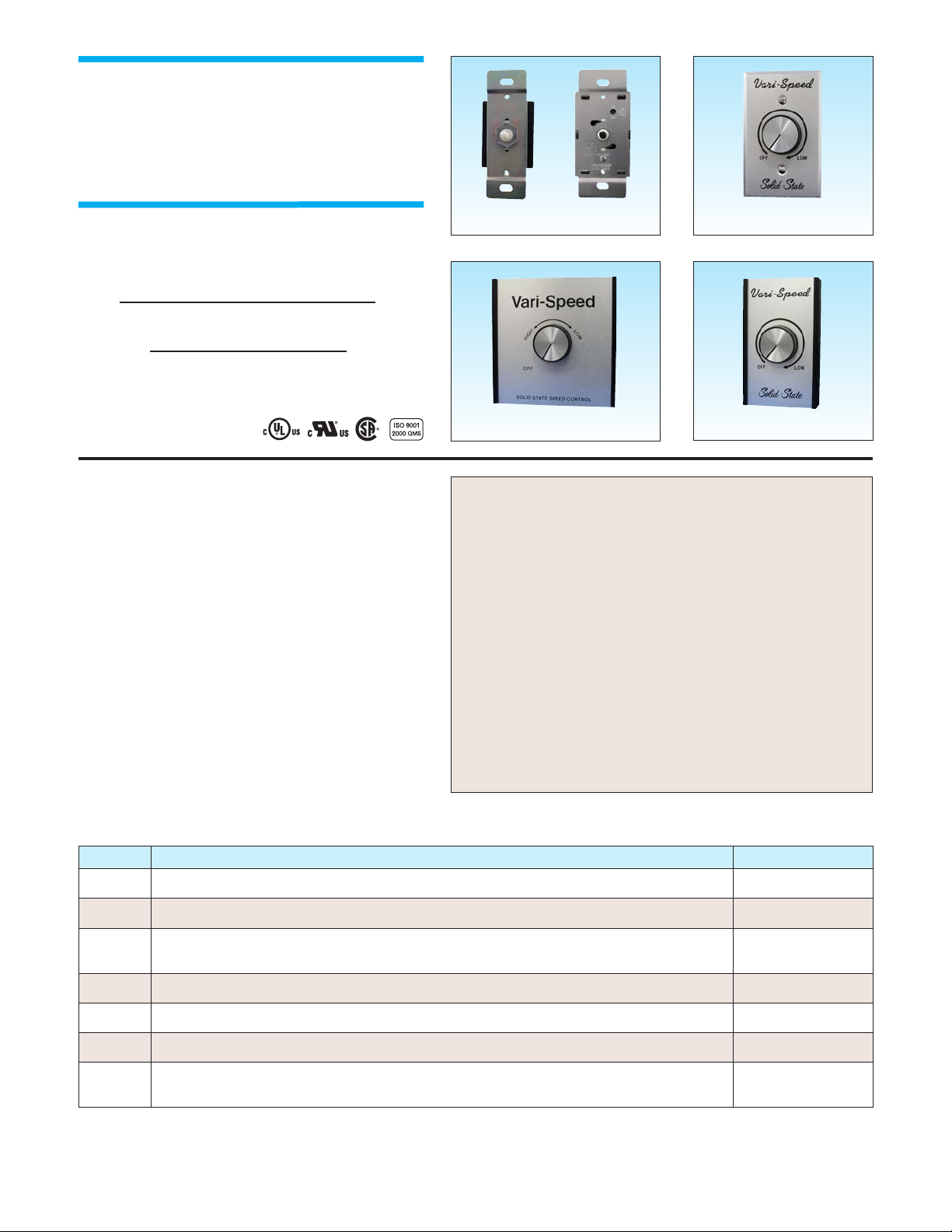
and built-in On/Off Line Switch are standard. These speed controls are
available as bulk packaged or in distributor type packaging with accessories such as: knob, dial plate, mounting hardware, instructions, and
individual carton. All models are designed to be mounted into a standard 2” X 4” electrical wall box.
• Fans • Fireplace Blowers • Humidifiers • Air Conditioners
• Ceiling Fans • Attic Fans
• Ventilators • Range Hoods
KBWC
DATA SHEET D-160
STANDARD FEATURES
• Built-In On/Off AC Line Switch
• Minimum Speed Trimpot
• RFI Filter (Provides RFI and EMI Suppression)
• All Models Mount in a Standard 2” x 4”
Electrical Wall Box
• Agency Approvals*
UL Listing / Recognition
CSA Certified
ISO-9001: 2000 QMS Certified
Suffix Description Example
C Omits mounting tabs (KBWC-16 only). KBWC-16C
F Adds Built-In Fuse (not available for Model KBWC-23NS). KBWC-15F
K
Mounting Kit: Includes individual packaging with dial plate, knob, mounting screws, wire connectors, and instructions.
Supplied standard on all models rated 8 Amps and above.
KBWC-15K
L Adds auxiliary lead (3-wire control). KBWC-15L
4L Adds DPDT On/Off Switch (4-wire control) (Model KBWC-25 only). KBWC-25 (4L)
NS Omits On/Off Switch. KBWC-15NS
R
Reverses control output from standard rotation. Standard: Controls with On/Off Switch – Off to High to Low. Controls
without On/Off Switch (suffix “NS”) – Low to High.
KBWC-15R
OPTIONAL FEATURES (See Options Table)
• Custom Packaging
• Special Lead Lengths, Colors, and Terminations
OPTIONS (Add Suffix to Model No.)
Note: *See Electrical Ratings table for agency approvals by Model No.
TYPICAL APPLICATIONS
© KB Electronics, Inc., Coral Springs, FL 33065
Pkg.“B”
Pkg.“C”
Dial Plate & Knob Pkgs. “B” & “C”
Pkg.“D”
Pkg.“E”
Wall-Mount Series
Solid-State
Variable Speed AC Motor Controls
For Use with Shaded Pole,
Permanent Split Capacitor (PSC)
and Universal Motors
Ratings: 2.5 thru 15.0 Amps
115 and 230 VAC – 50/60 Hz
Page 2
Model No.
AC Line Input Voltage
(Volts AC – 50/60 Hz)
Maximum Current Rating
(Amps RMS)
Ambient Temperature
(ºC)
Agency Approvals
Package
Type
KBWC-13 115 2.5 25
√ √
B
KBWC-15 115 5 40
√ √
C
KBWC-16 115 6 25
√
C
KBWC-18K
1
115 8 40
√ √
D
KBWC-110K
1
115 10 25
√ √
D
KBWC-110K
1
115 10 40
√ √
E
KBWC-112K
1
115 12 40 E
KBWC-115K
1
115 15 25
√
E
KBWC-23
2
230 2.5 25
√
B
KBWC-25
3
230 5 40
√
C
KBWC-26 230 6 25 C
KBWC-28K
1
230 8 40
√
D
KBWC-210K
1
230 10 40 E
KBWC-212K
1
230 12 40 E
KBWC-215K
1
230 15 25 E
KBWC-35 277 5 25
√
C
KBWC-36 277 6 25 C
KBWC-38K
1
277 8 25 D
KBWC-310K
1
277 10 25 D
KBWC-312K
1
277 12 25 E
KBWC-315K
1
277 15 25 E
Notes: 1. Models rated 8 Amps and above include Mounting Kit (suffix “K”). 2. Only model containing suffix “NS” is UL Recognized. 3. Only Model KBWC-25 (4L) is UL Recognized. 4. The maximum Locked Rotor current for UL listed controls is 6 times the Maximum Current Rating.
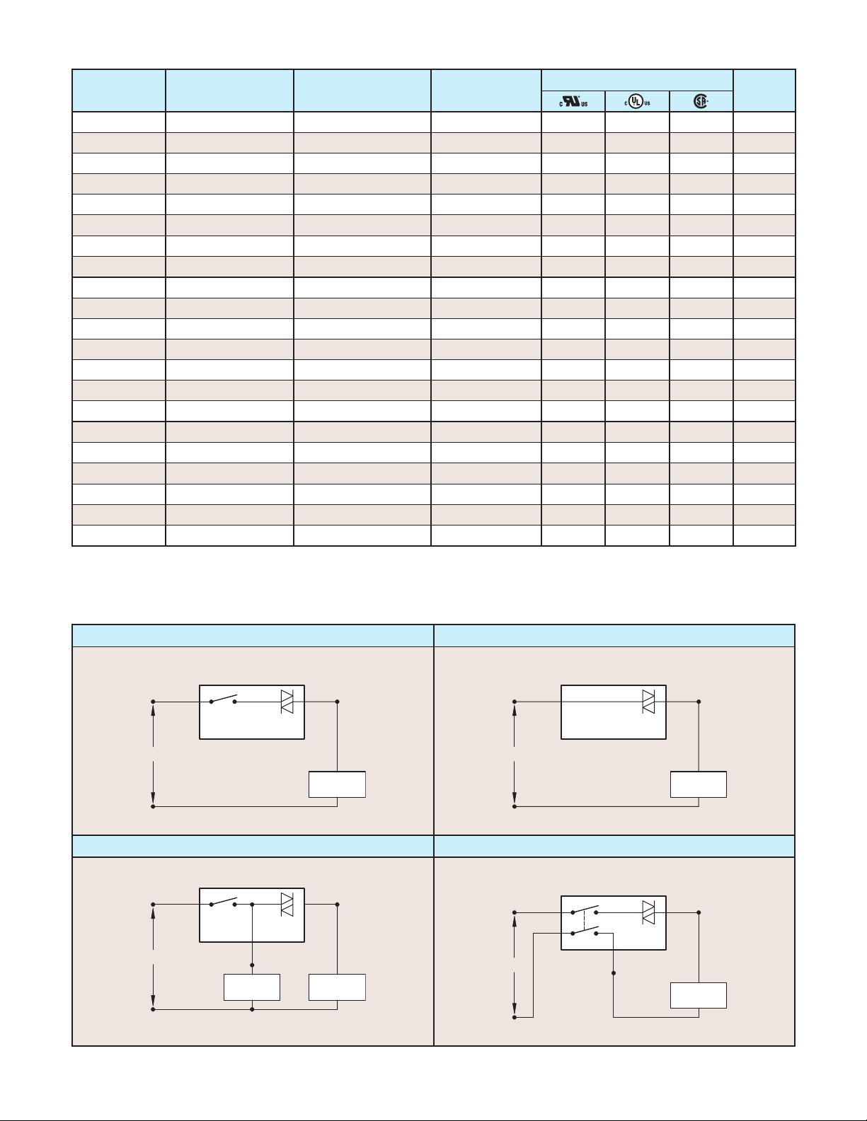
ELECTRICAL RATINGS AND AGENCY APPROVALS
2-Wire Controls with On/Off Switch (Standard) 2-Wire Controls without On/Off Switch (Suffix “NS”)
A
A
3-Wire Controls with Auxiliary Lead (Suffix “L”) 4-Wire Controls with DPDT On/Off Switch (Suffix “4L”)
A
A
CONNECTION DIAGRAMS
© KB Electronics, Inc., Coral Springs, FL 33065
DATA SHEET D-160
2
SPEED CONTROL
BLACK BLACK
C LINE
C LINE
BLACK
SWITCH
BLACK
TRIAC
CONTROLLED
LOAD
SPEED CONTROL
BLACK
SWITCH*
C LINE
*DO NOT EXCEED CURRENT RATING OF SWITCH
RED
AUXILIARY
LOAD
WHITE
TRIAC
C LINE
CONTROLLED
LOAD
RED
RED
SPEED CONTROL
SPEED CONTROL
SWITCH
BLACK
TRIAC
CONTROLLED
LOAD
BLACK
TRIAC
CONTROLLED
LOAD
Page 3

KBWC-13, 23 (Pkg. B)
Mechanical Specifications (Inches/mm)
KBWC-15, 16, 25, 26, 35, 36 (Pkg. C)
Mechanical Specifications (Inches/mm)
KBWC-18K, 110K, 28K, 38K, 310K (Pkg. D)
Mechanical Specifications (Inches/mm)
Dial Plate and Knob Kit (Suffix “K”)
Mechanical Specifications (Inches/mm)
KBWC-110K, 112K, 115K, 210K, 212K, 215K, 312K, 315K, (Pkg. E)
Mechanical Specifications (Inches/mm)
DATA SHEET D-160
© KB Electronics, Inc., Coral Springs, FL 33065
3
4.00
102
3.25
82.6
2.38
60.3
2.18
55.4
LEADS STRIPPED
0.5
12.7
1.25
31.8
1.75
44.5
LEAD LENGTHS
6.00
152
1.25
31.8
1.93
49.0
MOUNTING TAB OMITTED
ON SUFFIX "C" MODELS
2.38
60.3
3.25
82.6
4.13
105
LEADS STRIPPED
LEAD
LENGTHS
6.00
152
0.5 2.131.77
SUFFIX "C"
MODELS
ONLY
2.75
69.3
HI
MIN
SPEED
ADJ
LO
MOUNTING TAB OMITTED
ON SUFFIX "C" MODELS
1.54
39.1
44.9
2.75
69.9
2.50
63.5
1.50
38.1
2.55
64.8
54.112.7
Vari-Speed
OFF
Solid State
2.75
69.9
LOW
Vari-Speed
4.50
2.38
60.3
114
OFF
LOW
4.50
114
LEAD LENGTHS
LEADS STRIPPED
Solid State
4.50
114
Vari-Speed
HIGH
OFF
SOLID STATE SPEED CONTROL
LOW
4.50
114
LEAD LENGTHS
6.00
152
LEADS STRIPPED
0.5
12.7
2.55
64.8
1.38
35.1
6.00
12.7
2.55
64.8
152
0.5
2.55
64.8
1.38
35.1
Page 4

APPLICATION NOTES
1. Radio Frequency Interference (RFI): All solid-state speed controls generate annoying radio noise on the AM band. KB speed
controls contain, as standard, a high-gain RFI suppression filter which significantly reduces this interference.
2. Low End Set Point (Minimum speed): All 115 Volt input speed controls are factory set to 60 Volts AC output (±3 Volts), as
standard. All 230 Volt input speed controls are factory set to 120 Volts AC output (±6 Volts), as standard. All controls are factory
calibrated using an average responding AC voltmeter. Custom voltage settings are available.
3. Motor Suitability: Motors must be loaded to near full capacity with the appropriate fan blade in order to achieve proper speed
control. Generally, motor suitability is established by determining motor speed as a function of applied voltage. A motor is
determined as suitable if it changes speed linearly over a wide range of voltage.
It is required that all motors contain a built-in thermal overload protector when used with solid-state speed controls.
4. 230 & 277 VAC Controls: To achieve maximum reliability, all 230 VAC controls contain snubber networks that utilize Y-Type
capacitors and flame-proof resistors. In addition, all 277 VAC controls contain MOV Transient Suppression.
5. Temperature Test: The non-sinusoidal output voltage of a solid-state speed control may increase motor heating. Therefore, it is
necessary that a temperature test be performed to ensure that the motor is operating within manufacturer’s specifications.
6. Leads: All leads are approximately 6” (15 cm) long and stripped 1/2” (1.25 cm). Custom lead lengths, colors, and terminations
also available.
DATA SHEET D-160
KB ELECTRONICS, INC.
12095 NW 39th Street, Coral Springs, FL 33065-2516 • (954) 346-4900 • Fax (954) 346-3377
Outside Florida Call Toll Free (800) 221-6570 • email – info@kbelectronics.com
www.kbelectronics.com
(A42012) – Rev. B – 3/2004
OTHER AC MOTOR SPEED CONTROLS
RATINGS
2.5 Amps AC at
115 and 230 Volts AC 50/60 Hz
1.6 and 3 Amps at
115 and 230 Volts 50/60 Hz
1.6, 2.5 and 4 Amps at
115 and 230 Volts AC 50/60 Hz
300 Watts, 3 Amps AC at
125 Volts AC 50/60 Hz
DESCRIPTION
PANEL MOUNT: For ceiling fans, range hoods, vibrators, humidifiers, air conditioners, fireplace
blowers, window fans, etc. Designed for Shaded Pole, AC/DC, and Permanent Split Capacitor Motors.
PLUG-IN: For incandescent lamps and
wood-burning fireplaces and stove fans.
Plugs into a standard 115 Volt AC outlet.
KBNH
KBMS KBMC
Dial-A-Temp
 Loading...