

Page 1
DIRECT FIRED DIGITAL TEMPERATURE CONTROL
INSTALLATION, OPERATION, AND MAINTENANCE
MANUAL
This manual covers the following products:
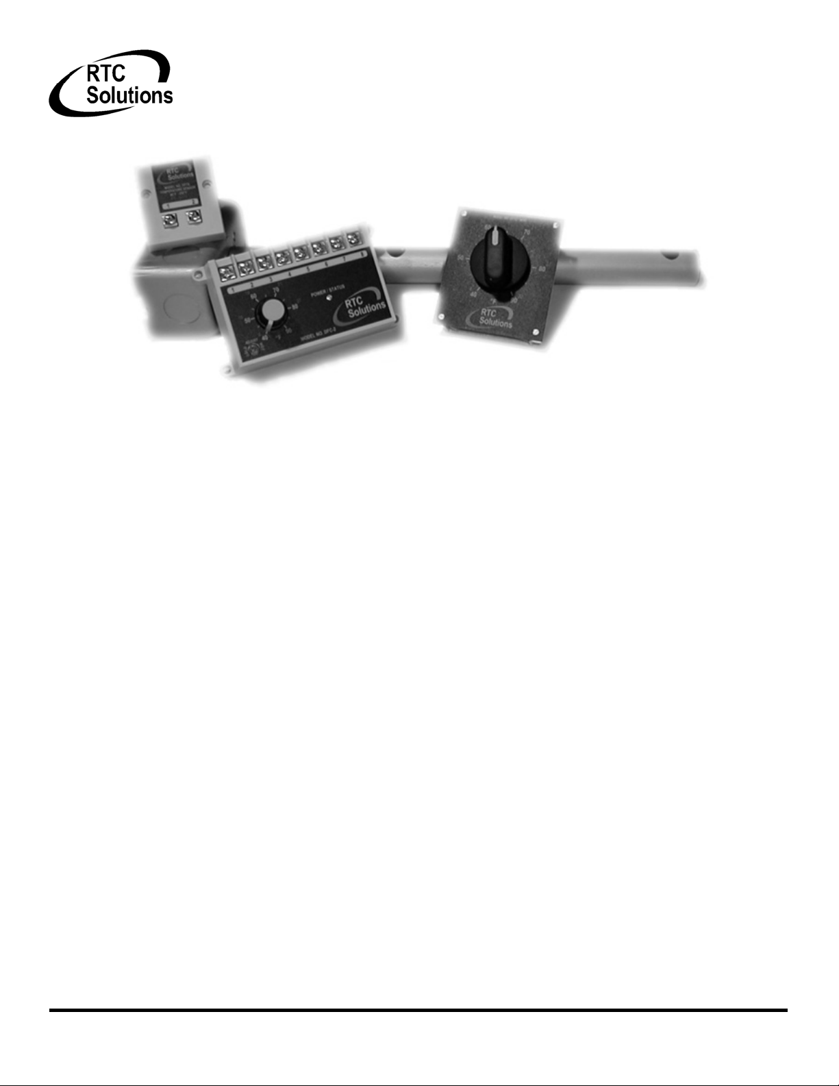
DFC-1 Standard direct fired temperature control 0-24VDC output
DFC-2 Direct fired control with integral 40-90°F (4-32°C) dial 0-24VDC output
DFTS Temperature senor 40-250°F (4-121°C)
DFTD-XXXX Temperature dial 5 selectable ranges
DAT-12 Discharge air tube
PWM-10V PWM to 10V output converter
Table of Contents
Overview ............................................................................................................................................................................................................................................................ 2
Specifications ..................................................................................................................................................................................................................................................... 2
Power Requirements .................................................................................................................................................................................................................................... 2
DFC Ambient Temperature Limits ............................................................................................................................................................................................................ 2
DFTS/DFTD Ambient Temperature Limits ............................................................................................................................................................................................ 2
Accuracy ........................................................................................................................................................................................................................................................ 2
Installation ......................................................................................................................................................................................................................................................... 2
Wiring ................................................................................................................................................................................................................................................................. 2
Standard control with remote set point .................................................................................................................................................................................................... 2
Standard control with integral set point ................................................................................................................................................................................................... 3
Optional room space control ...................................................................................................................................................................................................................... 3
Optional multiple set point temperature control .................................................................................................................................................................................... 3
Operation ........................................................................................................................................................................................................................................................... 4
Start up ........................................................................................................................................................................................................................................................... 4
Sequence of operation .................................................................................................................................................................................................................................. 4
Calibration ..................................................................................................................................................................................................................................................... 4
Troubleshooting ............................................................................................................................................................................................................................................ 4
DFTS and DFTD Resistance chart .............................................................................................................................................................................................................. 4
DOC# T0001 11.14.2006 DFC-1 O&M
Ph. (919) 845-1579 www.RTC-Solutions.com 755 Sw 120
Fax (919) 845-8102 Email:[email protected] Davie, FL 33325
1
th
Way
Page 2
Overview
The Roof Top Control Solutions direct fired digital temperature control is a microprocessor based control that utilizes an intelligent PID software
algorithm to modulate gas flow to a burner in direct fired make up air applications. The closed loop system contains three components including the
direct fired temperature sensor (DFTS), the direct fired control (DFC), and the direct fired temperature dial (DFTD). The system compares the discharge
temperature of the heating unit to the set point dial 40 times per second insuring accurate and repeatable temperature control. The software provides
smooth output control eliminating excessive swings observed with older analog systems. A 10 second start up delay is standard, and an onboard LED
indicates simple diagnostics.
Specifications
Power Requirements
DFC Ambient Temperature Limits
Storage
Operating
DFTS/DFTD Ambient Temperature Limits
Storage
Operating
Accuracy
24VAC 50/60Hz 20VA isolated class II
transformer
-40-140°F (-40-60°C)
-40-140°F (-40-60°C)
-40-250°F (-40-121°C)
-40-250°F (-40-121°C)
+/-3°F (1°C)
Installation
All control wiring should be shielded with the shielding grounded and/or the wiring should be run in separate conduit from
any high voltage wires. Interference from these sources could cause control function errors or permanent damage. The DFC
control should be mounted in a housing free from the elements of weather. Insulated fork terminal terminations are
recommended for best contact when attaching wiring to the provided screw terminals. Models DFC-1 and DFC-2 can drive up
to a .5 amp 24VDC direct acting solenoid.
J1
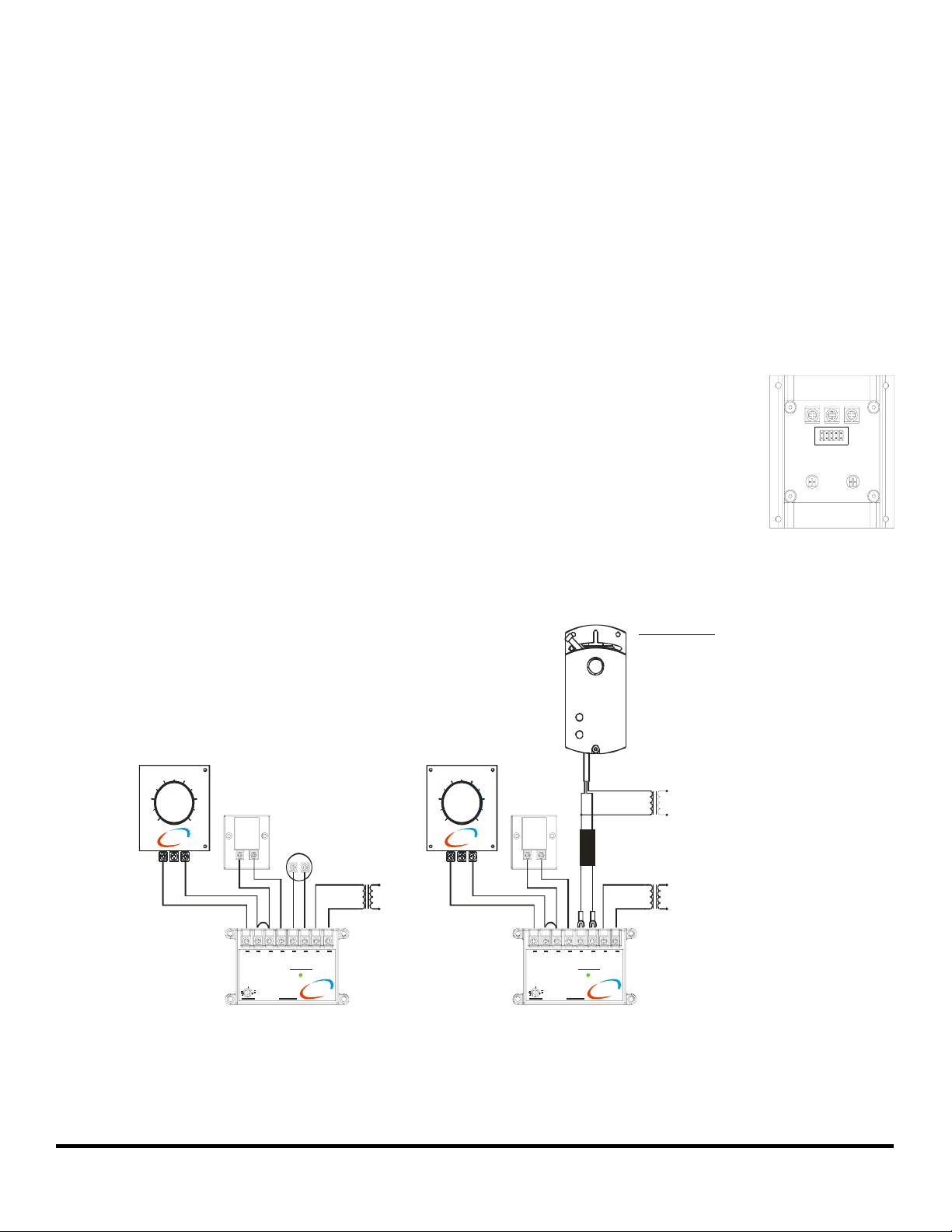
The DFTD can be set to 5 different temperature ranges by moving jumper J1 as shown in Figure 1 on the back of the dial to the
desired position. 5 different temperature overlays are available to match the range chosen.
** Important! When using the PWM-10V output converter to connect the DFC to a motorized actuator, or any other device
with it’s own power supply, the DFC must have it’s own isolated transformer separate from the power source for the
actuator, or the control may be damaged.
Figure 1
Wiring
Standard control with remote set point
DFTD
Temperat ure
selection dial
40 90
RTC
Solutions
132
7060
80
DFTS
Temper ature
senso r
12
24VDC Proportional
solenoid gas valve
20 VA Transformer
Proportional actuator
DFTD
Temper ature
selection dial
7060
50
40 90
RTC
Solutions
132
120 VAC24 VAC
80
DFTS
Temperature
senso r
12
BLACK
Wiri ng Conn ections
For Siemens actuator
Red(G) to 24 VAC
Black(G0) to 24VAC and Black on PWM -10V
Gray(Y) to Red on PWM-10V
Pink(U) No Connect
For Belimo actuator
1 to 24VAC an d Black on PWM-10V
2 to 24VAC
3 to Red on PWM-10V
20 VA Transformer
120 VAC24 VAC
*Important - Actuator must be
powered by isolated source from
PWM-10V
DFC contro l
20 VA Transformer
RED
120 VAC24 VAC
RTC
Solutions
DFC-1
RTC
Solutions
DFC-1
Figure 2 - Standard control wiring showing output options
2
DOC# T0001 11.14.2006 DFC-1 O&M
Ph. (919) 845-1579 www.RTC-Solutions.com 755 Sw 120
th
Way
Page 3

Standard control with integral set point
Optional room space control
DFTD
Optional room
thermosat
Temperature
selection dial
RTC
Solutions
132
DFTS
Temperat ure
sensor
24VDC Proportional
Solenoid Gas Valve
12
20 VA Transformer
RTC
Solutions
Figure 3 - Control with integral setpoint
DFTS
Temperature
sensor
24VDC Proportional
Solenoid Gas Valve
12
20 VA Transformer
120 Volt AC24 Volt AC
DFC-2
6 VA Transformer
120 VAC24 VAC
120 Volt AC24 Volt AC
DIGITAL SPACE
TEMPERATURE CON TROL
RTC
Solutions
DFTS
Temperat ure
sensor
12
24VDC Proportional
Solenoid Gas Valve
20 VA Transformer
120 Volt AC24 Volt AC
RTC
Solutions
DFC-1
RTC
Solutions
DFC-1
Figure 4 - Room space control with thermostat Figure 5 - Room space control with digital space control
A standard make or break thermostat with normally open contacts can be connected between terminals 1 and 2 as shown in Figure 4. When connected
in this way the thermostat may be set for a desired room temperature for space control applications. Potentiometer R1 on the back of the DFTD sets how
much the temperature will increase by when the room thermostat calls for more heat. When the room thermostat is satisfied, the discharge temperature
will return to the temperature set on the dial on the front of the DFTD. For proportional room space control, the DFC-1 can be connected as shown in
Figure 5. See RTC-1 literature for details.
Optional multiple set point temperature control
DFTD
Low temper ature
selection dial
7060
50
40 90
RTC
Solutions
132
80
DFTD
High t emperat ure
selection dial
110100
90
80 130
RTC
Solutions
132
120
DFTS
Temperat ure
sensor
12
24VDC Proportional
Solenoid Gas Valve
20 VA Transformer
RTC
Solutions
120 Volt AC24 Vo lt AC
DFC-1
Figure 6 - Control with multiple set points
More than one temperature dial can be connected as shown in Figure 3 for applications such as paint spray booths or process control.
DOC# T0001 11.14.2006 DFC-1 O&M
3
Ph. (919) 845-1579 www.RTC-Solutions.com 755 Sw 120
th
Way
Page 4

Operation
Start up
Setting low fire - The minimum firing rate may be set by removing the wire from terminal number 6 on the DFC control. This disconnects the power to
the control valve. Refer to the control valve manufactures literature for this adjustment.
Setting high fire – The maximum firing rate may be set by removing the wire from terminal number 4 on the DFC control. This disconnects the
discharge air sensor and sets the output to the control valve to it’s maximum. Refer to the control valve manufactures literature for this adjustment.
Sequence of operation
Upon applying power to the DFC control the 10 second start up delay will begin indicated by a slow blinking LED (about once every 2 seconds) on the
face of the control. After the start up delay has completed, the LED will turn solid and the control will begin modulating the output as required. Any
system errors are indicated by a fast blinking LED (about twice per second) for instance when the discharge air sensor is disconnected or outside of the
normal operating range.
Calibration
The temperature control should maintain an accuracy of +/- 3°F (1°C). In the event that the discharge is inaccurate due to duct losses the control may be
calibrated in two ways. The potentiometer on the face of the DFC labeled “ADJUST” will adjust the discharge temperature by +/- 10°F (5°C) when
rotated. Rotating it clockwise will increase the temperature and counter clockwise will decrease the temperature. The system may also be adjusted from
the DFTD if installed by adjusting potentiometer R3 on the back in the same manner as the DFC procedure above.
Troubleshooting
The DFC control provides some diagnostics via the on board LED labeled “POWER/STATUS”. A system fault is indicated by a fast blinking LED (about
twice per second). This usually indicates that the sensor or dial are either disconnected or improperly wired. Check all connections per the included
wiring diagrams. The fault also may be caused by a damaged sensor or dial. Both devices may be tested with an Ohmmeter by removing the wires from
the DFC control and measuring across the device. The devices should measure between 12.8K and 7K OHMS. If there is a fault light and the devices
measure the proper resistance then the control may be damaged. If there is no fault light but the system is not modulating properly you may check the
control output by repeating the start up procedure and measuring terminals 5 and 6 on the DFC as follows.
For DFC-1 and DFC-2
Remove the wire from terminal number 4 on the DFC control and measure the voltage across terminals 5 and 6 with a voltmeter. The meter should read
from 20 to 24 Volts. If it does not, disconnect the wires from the valve and measure the output without the valve connected. If it reads 20 to 24 Volts,
refer to the valve manufactures literature for troubleshooting the valve. If it does not the control may be damaged.
DFTS and DFTD Resistance chart
Sensor Resistance Dial Resistance
Temp °F Temp °C 40-90 80-130 120-170 160-210 200-250
40 4.4 11214 11250
50 10.0 11029 11050
60 15.6 10835 10850
70 21.1 10635 10650
80 26.7 10429 10450 10380
90 32.2 10219 10250 10180
100 37.8 10005 9980
110 43.3 9789 9780
120 48.9 9573 9580 9590
130 54.4 9356 9380 9390
140 60.0 9142 9190
150 65.6 8930 8990
160 71.1 8723 8790 8700
170 76.7 8521 8590 8500
180 82.2 8325 8300
190 87.8 8138 8100
200 93.3 7959 7900 8060
210 98.9 7791 7700 7860
220 104.4 7634 7660
230 110.0 7490 7460
240 115.6 7360 7260
250 121.1 7246 7060
DOC# T0001 11.14.2006 DFC-1 O&M
Ph. (919) 845-1579 www.RTC-Solutions.com 755 Sw 120
Fax (919) 845-8102 Email:[email protected] Davie, FL 33325
4
th
Way
 Loading...