

Page 1
A0011036
April 2011 Rev. 15
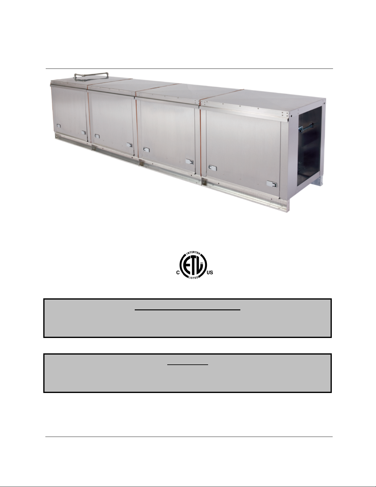
Pollution Control Unit
Installation, Operation, and Maintenance Manual
Pollution Control Unit
Save these instructions. This document is the property of the owner of this equipment and is
required for future maintenance. Leave this document with the owner when installation or
service is complete.
RECEIVING AND INSPECTION
Upon receiving unit, check for any interior and exterior damage, and if found, report it
immediately to the carrier. Also check that all accessory items are accounted for and are
damage free.
WARNING!!
Installation of this unit should only be performed by a qualified professional who has read and
understands these instructions and is familiar with proper safety precautions. Read this
manual thoroughly before installing or servicing this equipment.
Page 2

2
TABLE OF CONTENTS
WARRANTY ................................................................................................................................................ 3!
LISTINGS..................................................................................................................................................... 4!
APPLICATION ............................................................................................................................................. 4!
INSTALLATION ........................................................................................................................................... 5!
Site Preparation ....................................................................................................................................... 5!
Joint Sealant ............................................................................................................................................ 5!
Sealant Features ..................................................................................................................................... 5!
Ductwork.................................................................................................................................................. 6!
Unit Drains ............................................................................................................................................... 6!
Recommended MIN Ductwork Sizes................................................................................................... 6!
Equipment Rails....................................................................................................................................... 7!
Roof Mount Installation (Typical) ............................................................................................................. 7!
Indoor (Inline) Installation (Typical).......................................................................................................... 7!
Air Pressure Switch Option...................................................................................................................... 8!
Advanced Filter Pressure Monitoring Option ........................................................................................... 9!
HMI MENUS...................................................................................................................................... 10!
PCUFMM Wiring ............................................................................................................................... 11!
Troubleshooting................................................................................................................................. 12!
Fire System............................................................................................................................................ 13!
Climate Controlled Utility Cabinet...................................................................................................... 13!
OPERATION .............................................................................................................................................. 15!
Start Up.................................................................................................................................................. 15!
Special Tools Required ..................................................................................................................... 15!
Start Up Procedure............................................................................................................................ 15!
Troubleshooting ..................................................................................................................................... 16!
Troubleshooting Chart ....................................................................................................................... 16!
MAINTENANCE ......................................................................................................................................... 17!
General Maintenance ............................................................................................................................ 17!
Filter Information.................................................................................................................................... 17!
Standard Filter Part Numbers............................................................................................................ 18!
Optional Pre-Filters, High Eff, and HEPA Filter Part Numbers.......................................................... 18!
Optional Odor Control Media Part Numbers ..................................................................................... 18!
Gasket Type Chart................................................................................................................................. 19!
2 Weeks After Startup............................................................................................................................ 19!
Every Month........................................................................................................................................... 19!
Duct Cleaning ........................................................................................................................................ 19!
Yearly..................................................................................................................................................... 19!
Start-Up and Maintenance Documentation............................................................................................ 20!
Job Information.................................................................................................................................. 20!
PCU Information ................................................................................................................................ 20!
Maintenance Record ......................................................................................................................... 20!
Factory Service Department.............................................................................................................. 20!
Page 3

3
WARRANTY
This equipment is warranted to be free from defects in materials and workmanship, under normal use and
service, for a period of 12 months from date of shipment. This warranty shall not apply if:
1. The equipment is not installed by a qualified installer per the MANUFACTURER’S installation
instructions shipped with the product,
2. The equipment is not installed in accordance with federal, state and local codes and regulations,
3. The equipment is misused or neglected,
4. The equipment is not operated within its published capacity,
5. The invoice is not paid within the terms of the sales agreement.
The MANUFACTURER shall not be liable for incidental and consequential losses and damages
potentially attributable to malfunctioning equipment. Should any part of the equipment prove to be
defective in material or workmanship within the 12-month warranty period, upon examination by the
MANUFACTURER, such part will be repaired or replaced by MANUFACTURER at no charge. The
BUYER shall pay all labor costs incurred in connection with such repair or replacement. Equipment shall
not be returned without MANUFACTURER’S prior authorization and all returned equipment shall be
shipped by the BUYER, freight prepaid to a destination determined by the MANUFACTURER.
Page 4

4
LISTINGS
This pollution control unit (PCU) is ETL listed to standard UL-710 when installed in accordance with these
installation instructions and National Fire Protection Association Standard “NFPA 96, Standard for
Ventilation Control and Fire Protection of Commercial Cooking Operations.”
APPLICATION
The listed pollution control unit is suitable for use in commercial cooking installations for the removal of
smoke and grease laden vapors.
Grease duct installations require provisions for cleaning the interior of the duct. NFPA 96 cleanout
requirements are as follows:
1. A cleanout must be provided at each change of direction except where the entire length of duct
can be inspected and cleaned from either the hood or the discharge end.
2. On horizontal duct runs, at least one (1) 20” diameter opening must be provided. Where the
opening is smaller than 20” diameter, openings large enough to permit cleaning must be provided
at intervals of no more than 12’.
3. Openings in the duct must be at the side or the top, whichever is more accessible. When the
opening is on the side of the duct, the lower edge of the opening must be at least 1 ½” above the
bottom of the duct. For listed grease duct, this is accomplished by the use of the grease manifold
tee and cleanout cap.
4. On vertical duct runs where personnel entry is possible, access must be from the top of the riser.
Where entry is not possible, access must be provided at each floor.
NOTE: ACCESS REQUIREMENTS ARE SUBJECT TO CHANGE IN ACCORDANCE WITH LOCAL
CODE. LOCAL AUTHORITIES SHOULD BE CONSULTED FOR EXACT REQUIREMENTS. GREASE
DUCT MAY BE CONNECTED ONLY TO HOODS IN A SINGLE FIRE ZONE ON ONE FLOOR. DO
NOT CONNECT GREASE DUCTS TO ANY OTHER PART OF THE BUILDING VENTILATION OR
EXHAUST SYSTEM.
A grease fire can burn at extremely high temperatures. This system should be dismantled and inspected
after any exposure to a grease fire. Any section that is distorted or discolored should be replaced. All
joints in the system should be examined. Because the sealant expands to assure a positive seal in the
case of a fire, any sealant that has been exposed to high temperature must be replaced. This will ensure
that the system maintains its integrity against fire conditions in the future. The manufacturer of this PCU
cannot be responsible for grease duct systems that are not properly maintained or have been subjected
to one or more grease fires. Warranty and listing is void in a fire situation without consulting factory.
Grease duct systems size and capacity information may be obtained from the “ASHRAE Handbook –
Fundamentals” or from the “Air Pollution Engineering Manual” of the “US Environmental Protection
Agency.” Refer to the grease duct systems catalog for descriptions and dimensional data of parts.
Page 5

5
INSTALLATION
It is imperative that this unit is installed and operated with the designed airflow, filters, exhaust fan
placement, and construction in accordance with this manual. If there are any questions about any items,
please call the service department at 1-866-784-6900 for warranty and technical support issues.
WARNING: DO NOT RAISE PCU BY THE DOOR, FILTER FRAMES, OR UTILITY
CABINET – USE LIFTING LUGS PROVIDED OR A SLING.
Site Preparation
1. Provide clearance around installation site to safely rig and lift equipment into its final position.
Supports must adequately support equipment. Refer to manufacturer’s estimated weights.
2. Consider general service and installation space when locating unit. Allow a minimum of 36
inches of clearance on the filter removal side of the unit to replace filters.
3. Locate unit close to the space it will serve to reduce long, twisted duct runs.
4. Support unit above ground or at roof level high enough to prevent precipitation from being drawn
into unit.
5. The PCU is designed to operate in a negative pressure environment. Be sure to install the PCU
between the exhaust fan and hoods. This will also keep the fan cleaner during operation.
6. The PCU drains must be connected to the building grease interceptor or an approved building
drain. Black Iron or Stainless Steel Pipe must be used for this connection.
Joint Sealant
The joint sealant used to seal all internal joint assemblies is a 3M product. 3M Fire Barrier 2000 +
Silicone Sealant is a ready-to-use, gun-grade, one-component silicone elastomer that cures upon
exposure to atmospheric humidity to form a flexible seal. 3M Fire Barrier 2000 + Silicone Sealant, when
installed properly, will control the spread of fire before, during and after exposure to open flames. It will
stop the spread of noxious gas, smoke and water and maintain the integrity of fire rated assemblies and
construction. NO SEALANT SUBSTITUTES MAY BE USED.
Sealant Features
1. Superior adhesion.
2. Capable of withstanding 2000 °F + temperatures.
3. Class 25 sealant, per ASTM 920.
4. Re-enterable/repairable.
5. Provides up to 4-hours fire-rating.
6. Cures upon exposure to atmospheric humidity.
7. Working time 30 minutes.
8. Cure time 14 to 21 days.
9. Applied with a standard caulk gun.
Page 6
6
Recommended MIN Ductwork Sizes
PCU Size
Duct Height
Duct Width
PCU-1
23 in.
23 in.
PCU-2
30 in.
30 in.
PCU-3
35 in.
35 in.
PCU-4
43 in.
43 in.
PCU-5
50 in.
52 in.
PCU-6
46 in.
58 in.
Ductwork
The ductwork attached to this unit will significantly
affect the airflow performance. Flexible ductwork
and square elbows should not be used. Any
change in direction must be at least 5 duct
diameters away from the pollution control unit
inlet. The chart to the right shows the
recommended duct sizes for optimal performance.
The maximum velocity at the inlet of the
pollution control unit must be less than 1000
Feet Per Minute. Follow SMACNA guides and
recommendations for the remaining duct run.
Ensure duct connections are properly aligned and sealed. When the pollution control unit is used in
commercial grease ductwork, the ductwork connections must be FULLY WELDED to the PCU.
Clearance ratings of ductwork connected to the unit apply to the PCU as well. Ductwork must be listed or
installed in accordance with the IMC.
Unit Drains
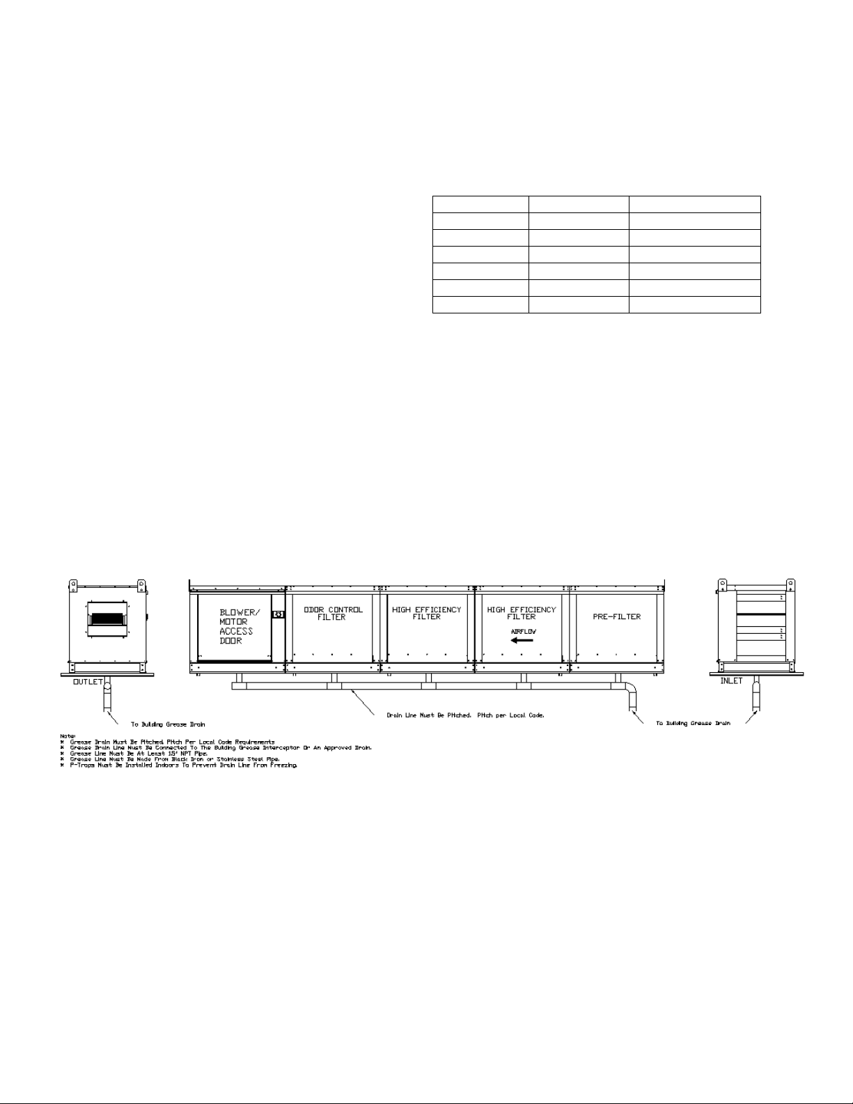
Each module of the Pollution Control Unit contains a drain that must be connected to an approved
grease interceptor or to an approved drainage point. The drain connections must be made with Black
Iron or Stainless Steel piping. This will allow the water collected in the unit, either from Self Cleaning
hood, ductwork cleaning, or from the Core Protection Fire System, to drain away from the unit. If installed
outdoors, the drains must be piped so that water cannot buildup in the pipes and burst due to freezing.
Page 7
7
Equipment Rails
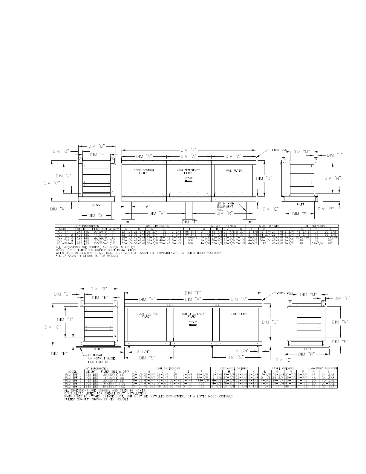
The unit should be installed on a curb and/or rail elevated not less than 14” above any roof surface.
Secure PCU to rails through vertical portion of the PCU base assembly flange using a minimum of eight
(8) lug screws, anchor bolts, or other suitable fasteners (not furnished). Shims may be required
depending upon equipment rail installation and roofing material. When installed indoors, uni-strut
channels may be used under the PCU for attachment to threaded rod from the roof structure above.
Check all fasteners for tightness. The diagrams below show different mechanical installation
configurations.
Roof Mount Installation (Typical)
Indoor (Inline) Installation (Typical)
Page 8
8
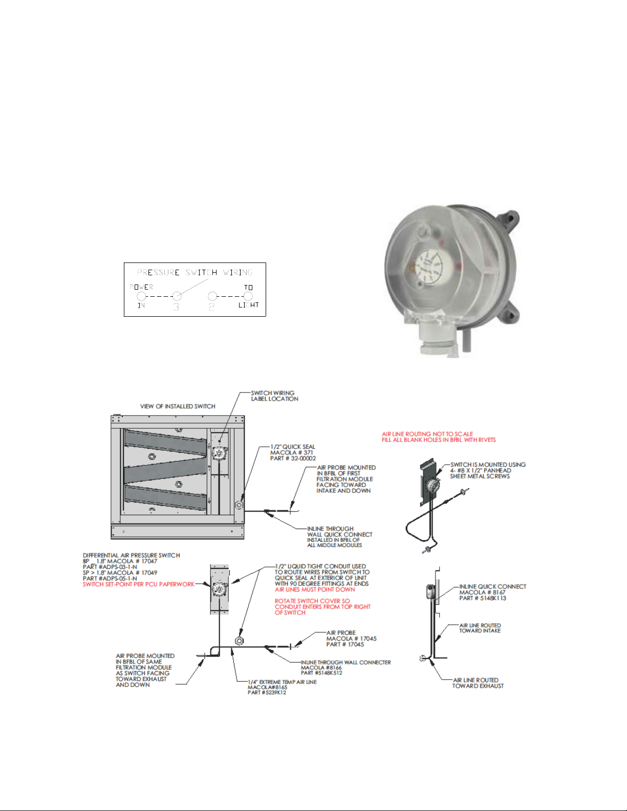
Air Pressure Switch Option
Switches are preset from plant to .15” w.c. above the internal static pressure of the PCU with clean filters.
Air pressure switch is located in downstream filter module. Route wiring from hood control panel to PCU
using ½” conduit through quick seal located near lower right area of filter module containing switch. Use
existing conduit in module to route wires from exterior of module to switch. Install wiring according to
label above switch. Be sure all conduit fittings are tight. Once filters become clogged, switch closes
illuminating light in kitchen. User should then clean or replace filters as required.
Page 9
9
Advanced Filter Pressure Monitoring Option
The PCU Filter Monitoring Module (PCUFMM) utilizes proprietary algorithms to make determinations
about filter loading percentages as well as fault conditions, such as missing filters and missing doors.
These algorithms take into consideration known characteristics and interactions of many specific filter
combinations, stored calibration values derived from measurements taken at the time of test and balance,
and measurements of the dynamically changing current operating conditions such as demand
ventilation. Personnel servicing the PCU have direct access to operating characteristics and fault
conditions thru the use of an HMI (Human Machine Interface), which is conveniently located directly on
the PCU. Accurate monitoring of PCU filter conditions not only ensures proper operation of the PCU, but
can also reduce the operating cost of the PCU by reporting the condition of each individual filter module.
This can eliminate the needless replacement of filters that have not yet reached the end of their useful
life.
Features and Benefits:
• Monitors pressure drop across each filter module of the Pollution Control Unit (PCU).
• Fans and Cooking equipment will shut off for Missing Door (of the unit) fault or Missing Filter fault.
• Detects Filter Clogged Condition. If clogged condition persists for 24 hours, an audible alarm will
begin to sound. If the clogged condition continues to persist for an additional 48 hours, a signal
will be sent to the electrical control package that will prevent the fans and cooking equipment
from restarting the next time they have been manually turned off.
Several techniques are employed to insure the validity of the pressure readings. Consequently
disturbances caused by events such as fan starting and stopping, filter door removal and sudden
changes in building or atmospheric pressure will cause a delay in updating the faults until the
disturbances have subsided and enough fresh data has been gathered.
The filter monitoring system has 8 ports which are used based on the number of filter modules in the PCU
assembly. The following chart shows the port connections used for different PCU configurations. PORT 7
is used only if the PCU assembly has a blower installed. The unused ports remain exposed to the space
in the cabinet. Port 8 is used to measure ambient pressure, external to the PCU.
PCUFMM PORT CONNECTIONS
No of PCU filter
modules
PORT 1
PORT 2
PORT 3
PORT 4
PORT 5
PORT 6
PORT 7
PORT 8
1
YES
YES
NO
NO
NO
NO
YES/NO
YES
2
YES
YES
YES
NO
NO
NO
YES/NO
YES
3
YES
YES
YES
YES
NO
NO
YES/NO
YES
4
YES
YES
YES
YES
YES
NO
YES/NO
YES
5
YES
YES
YES
YES
YES
YES
YES/NO
YES
HMI Screen
Page 10

10
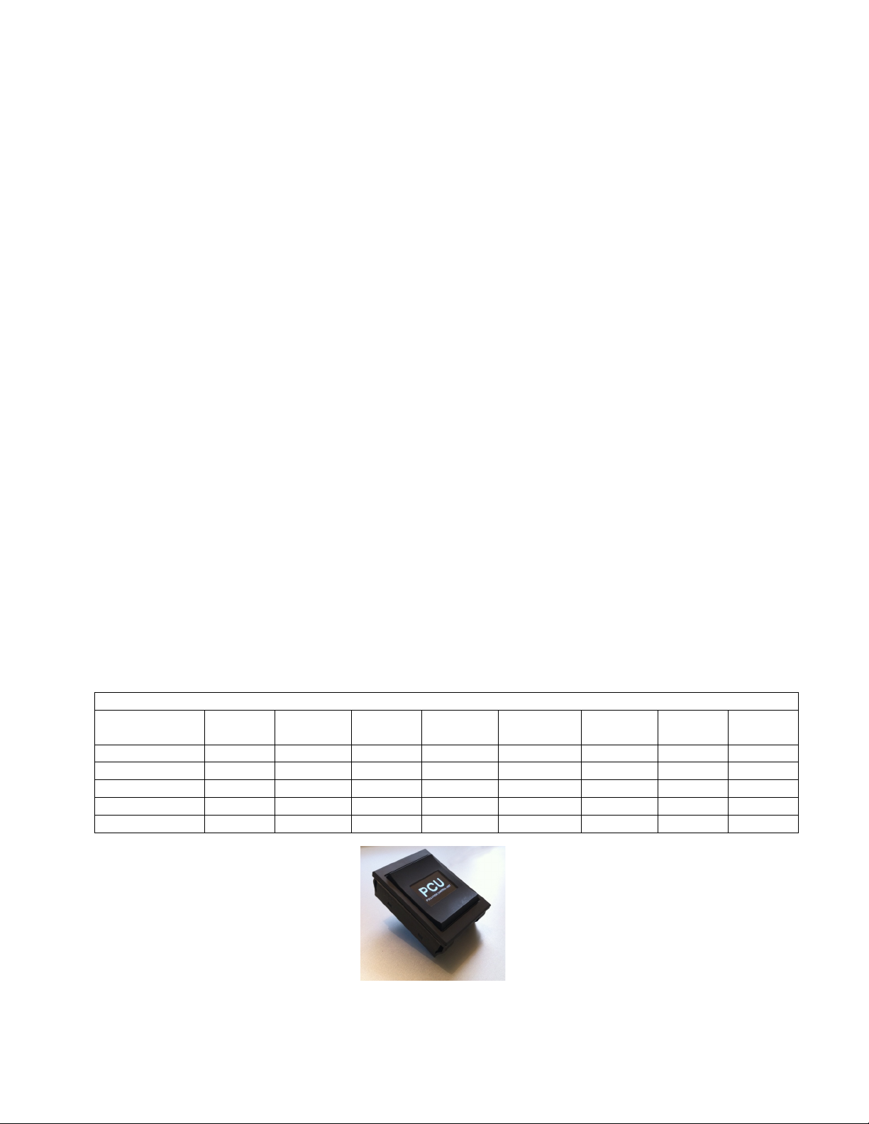
The HMI for the PCU filter pressure monitor is a “Smart” rocker switch installed with a built in organic LED
monochrome graphic display. The rocker switch has three momentary switches, one is actuated when the
top portion of the rocker is depressed, the second one is actuated when the middle portion of the rocker is
depressed and the third is actuated when the bottom portion of the rocker is depressed.
General Navigation Rules
• Top button is used to go to the previous menu.
• Middle button is used to select or enter the current selection choice.
• Bottom button is used to step through the available selection choices.
• Screen saver is automatically selected after 2 minutes of inactivity. During normal operation the
screen saver is a blank screen, but if there is a fault it will flash the fault screen.
HMI MENUS
Following are the various menus that appear in sequential order during navigation thru the HMI.
• PCU logo
This screen shows up upon unit start up.
• Filter Status
Displays percentage of filter clogging for up to 5 filter modules or “Missing” if a module’s
filters are missing. “Calibration Required” will be displayed if the calibration sequence has
not been completed upon PCU unit start up.
• Pressures
This menu has 2 screens. The first screen displays pressure drop for up to 5 filter
modules. The second screen displays the total pressure drop across the PCU, PCU inlet
static and discharge pressure if configured.
• Faults
The following are various faults that are displayed on the HMI. “No faults” are displayed if
the PCU is functioning as desired.
“Calibration Required”
“Fltr Clogged”
“Fltr Missing”
“PCU clogged”
“72hr Clog”
“Missing Door”
• Reset faults
Once a fault is activated and the necessary corrected action is taken this menu choice is
selected to clear the fault.
• Calibration
A 4 digit PIN (1234) is entered using bottom and middle buttons. Once entered correctly
the new filter calibration sequence is started. “Calibrating” will be displayed until
calibration is complete. A percentage complete will also be displayed. Fan speed must
be maintained at 100% for the entire calibration time. If fluctuations are detected the
calibration sequence will restart from zero percent.
Calibration MUST be performed after PCU unit start up or with any PCU or Hood Filter
configuration change. Calibration is ALWAYS performed with clean PCU filters.
Page 11
11
• Config
PCU is configured at the factory. PCU has to be re configured only if filter types in any
filter module are changed.
To Configure the PCU a 4 digit PIN (5678) is entered using middle and bottom buttons.
The following are the sub menus available
Configure PCU modules
• This sub menu steps through the process of configuration. Module count
for the PCU assembly is entered followed by the filter type for each
module.
• The bottom button is used to step though the available filter types. The
middle button is used to select the desired filter type for each module.
PCU number
• The number for this PCU will be displayed in reverse video and is
selected using the bottom and middle buttons. This number allows for up
to 8 PCUs to exist on one modbus network. Once the middle button is
pressed to select the PCU number, a prompt will be displayed to press
any button to reboot the PCU filter monitor module. This is required for
proper operation after the modbus address is changed.
• Information
This menu has 4 screens which can be stepped through using the bottom button. The
first screen displays the filter type for up to 5 modules. The second screen displays the
software revision, number of modules, the configuration number currently selected, PCU
number and software CRC. The third screen displays the calibration values for modules 1
through 3. The fourth screen displays the calibrations values for modules 4 and 5, the
total calibration value across the PCU and the inlet calibration value.
PCUFMM Wiring
Before connecting power to the control, read and understand the
entire section of this document. As-built wiring diagrams are
furnished with each control by the factory, and are attached either to
the door of the unit or provided with the paperwork packet.
Electrical wiring and connections should be done in accordance
with local ordinances and the National Electric Code, ANSI/NFPA
70. Be sure the voltage and phase of the power supply and the
wire amperage capacity is in accordance with unit nameplate.
1. Always disconnect power before working on the
PCUFMM. Lock and tag the disconnect switch to breaker to
prevent accidental power up.
2. 120VAC should be wired from terminals H1, N1, P2, P3, P4
and AA to like terminals in the Electrical Control Package.
• For an EMS, Terminal H1 is wired to H1B and N1,
P2, P3, P4, AA are wired to like terminals in the
Electrical Control Package.
• For an EMS PLUS, Terminal H1 is wired to H1B
and N1, MBA, MBB, MBC are wired to like
terminals in the Electrical Control package. MBA,
MBB and MBC are connected to the EMS plus
using shielded single twisted pair cable like Beldon
# 88760.
Copper Wire Ampacity
Wire Size AWG
Maximum Amps
14
15
12
20
10
30
8
50
6
65
4
85
WARNING!!
Disconnect power before
installing or servicing
control. High voltage
electrical input is needed
for this equipment. This
work should be
performed by a qualified
electrician.
Page 12
12
3. Make certain that the power source is compatible with the requirements of your equipment. The
system wiring schematic identifies the proper phase and voltage of the equipment.
4. Before connecting control to power source, verify power line wiring is de-energized.
5. Do not kink the power cable and never allow the cable to come in contact with oil, grease, hot
surfaces or chemicals.
6. Before powering up the system, make sure that the interior of the control is free of loose debris or
shipping materials.
Troubleshooting
The following table lists causes and corrective actions for possible faults shown on the HMI with the
Pollution Control Units. Review this list prior to consulting manufacturer.
Fault
Potential Cause
Corrective Action
Unit not calibrated upon start up
Calibrate the PCU
Calibration Required
Unit taking too long to calibrate
Varying airflow at inlet of the PCU
Check for blocked Atmospheric
port
Filters in a module are clogged
Replace filters in module showing
“100% Clog” with clean filters of
the same filter type
Ftlr Clogged
Access door in duct left open
Close access door in duct
Filters in a module are missing
Place filters back in Missing Filter
module and check for missing
filters in all other modules
Hood filters are clogged
Clean filters in the hood
Ftlr Missing
Blocked Inlet to the PCU
Make sure nothing is blocking air
flow entering the PCU
Pressure drop across entire PCU
exceed allowable limits
Replace filters in module showing
maximum percentage clog with
clean filters of same type
PCU clogged
Access door in duct left open
Close access door in duct
Filters in a module are clogged for
72 hours
Replace filters in module showing
“100% Clog” with clean filters of
the same filter type
Pressure drop across entire PCU
exceed allowable limits for 72
hours
Replace filters in module showing
maximum percentage clog with
clean filters of same type
72hr Clog
Access door in duct left open for
72 hours
Close access door in duct
Missing Door
Missing Door in one of the
modules
Place door back in modules
having missing door and check for
missing filters in each module
ATTENTION!!
In order to prevent erroneous issuing of fault conditions, the monitoring system takes
several minutes to issue a fault.
FAULTS will not be detected if PCU is running outside Normal Hood operating
conditions.
Page 13
13
Fire System
Pollution Control Units require a fire system to be installed with the PCU. Ansul R-102 Fire Suppression
Systems are available for the PCU. This system uses fusible links or electric sensors set at 360° F to
activate the fire system. Outdoor installations require a climate controlled cabinet to ensure the fire
system does not drop below 32° F and does not exceed 130° F. See below for more information about
outdoor installations. The Pollution Control Unit fire system must be interlocked with a hood fire system
so that if the hood system activates, the PCU system activates. Reverse activation is not required by
code, but is recommended for safety. Details of this interlock can be found in the installation guide
provided by the fire system manufacturer.
In the event that the fire system is accidentally activated, all disposable filters must be replaced and the
prefilter cleaned. The agent used in the fire system can cause the filters to prematurely fail.
In the event that a fire occurs in the ductwork leading to the PCU or inside the PCU, the following must be
completed. The unit must be cleaned of all fire suppression chemicals and grease. The filters must be
replaced, this includes the prefilter. If any of the gasketing is damaged, replace the gasketing between
modules and between the doors. If any of the components that make-up the Pollution Control Unit are
damaged by fire, then that component must be replaced and inspected by factory trained service
personnel.
Installation, commissioning, or resetting of the fire system must be done by a
licensed fire system installer, per the guidelines set forth by the fire system
manufacturer.
Climate Controlled Utility Cabinet
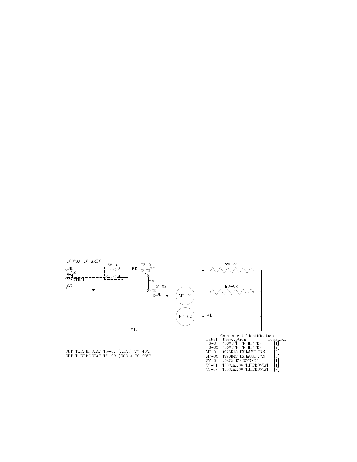
For outdoor installations, a climate controlled cabinet is available to house the fire system. This box
contains a heater, an exhaust fan, and thermostats to control the temperature inside the cabinet. The
Utility Cabinet thermostats come preset to heat below 40° F and cool above 90° F. The climate controlled
cabinet requires a dedicated 15 amp, 60 Hz, 115 volt, single phase electrical service.
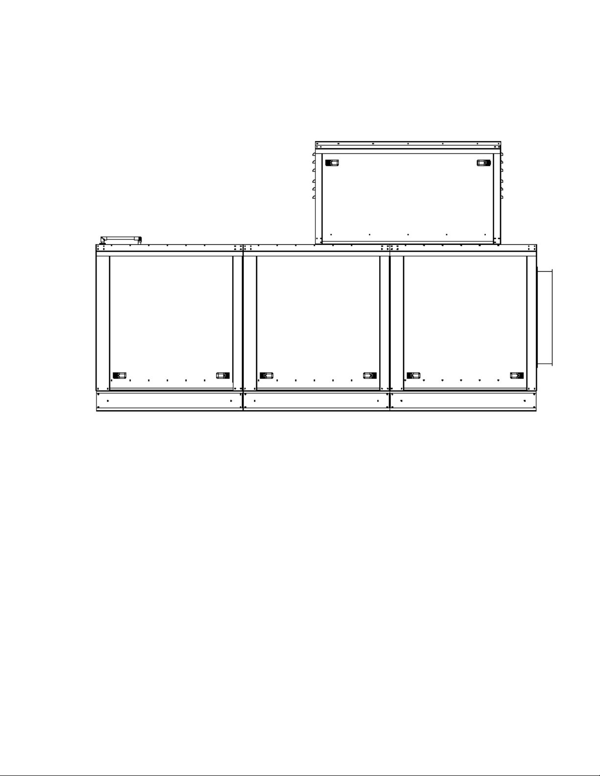
Typical Wiring Schematic for the Climate Controlled Utility Cabinet
Page 14
14
Utility Cabinet
Pollution Control Unit with Climate Controlled Utility Cabinet
Installed
Page 15

15
OPERATION
Prior to starting up or operating the PCU, check all fasteners for tightness. In particular, check the module
connection seal and the door seals. With power to the fan OFF, check the airflow direction of the filters as
they must match the label on the filter.
Start Up
Special Tools Required
• 3M Fire Barrier 2000 + Silicone Sealant
• Standard Hand Tools
Start Up Procedure
1. Check all fasteners and connections for tightness.
2. Inspect the air-stream for obstructions and install filters if missing.
3. Filters must be installed in the correct direction.
4. When the fan is started up, observe the operation and check for any unusual noises.
5. Inspect the entering and leaving ductwork connections. Ensure there are not leaks or pinholes in
grease duct. Grease rated duct should be continuously welded to the PCU.
6. If unit is installed on vibration isolators, ensure that the isolators are adjusted correctly leaving
plenty of spring force on the unit to absorb vibration.
Page 16
16
Troubleshooting
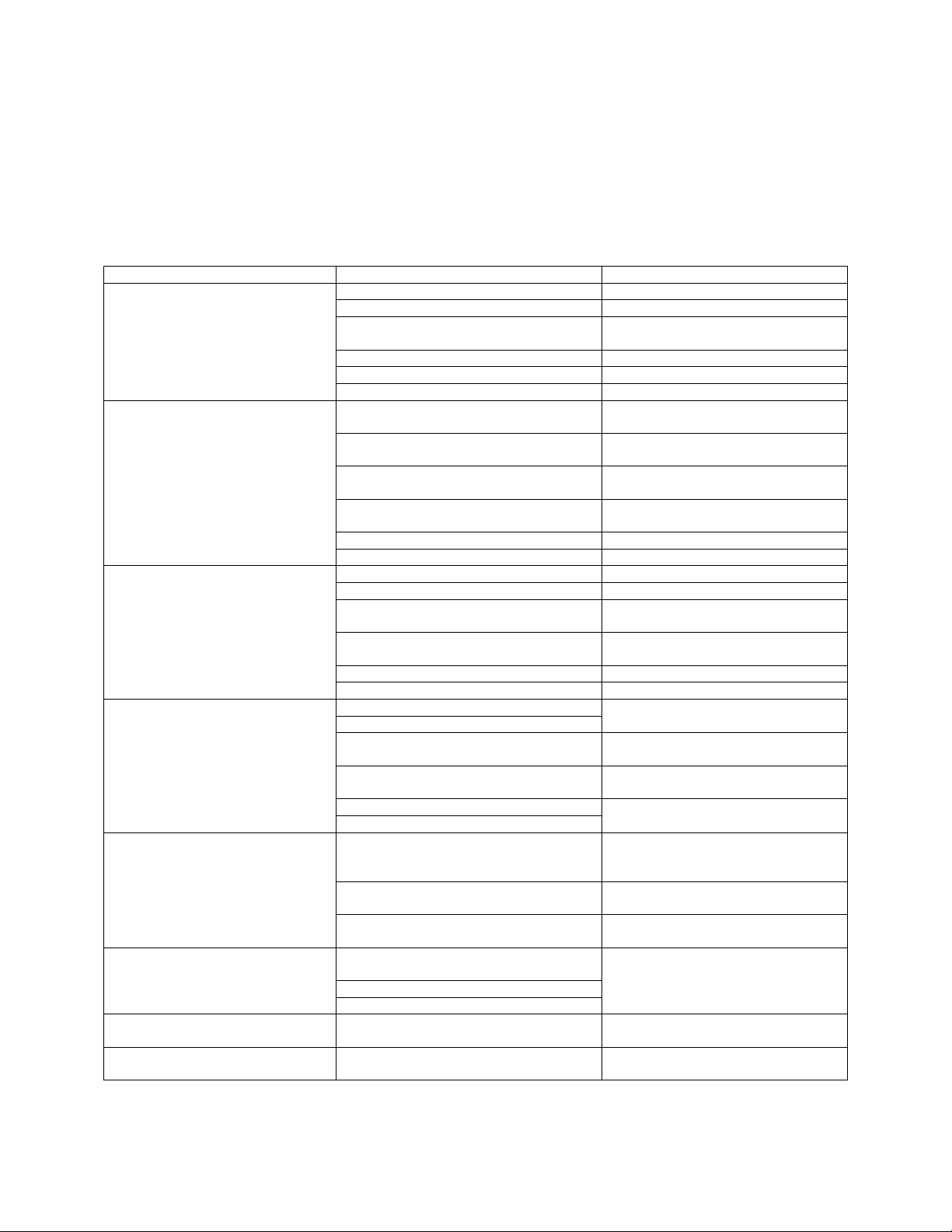
The following table lists causes and corrective actions for possible problems with the pollution control
units and the fan attached to the PCU. Review this list prior to consulting manufacturer.
Troubleshooting Chart
Problem
Potential Cause
Corrective Action
Filters not installed
Install all filters and unit doors
Fan speed is too high
Reduce fan RPM
Motor wired incorrectly
Check motor wiring to wiring
diagram located on fan motor
Overload in starter set too low
Set overload to motor FLA value
Motor HP too low
Determine if HP is sufficient for job
Fan Motor Overload / Excessive
Airflow
Duct static pressure lower than design
Reduce fan RPM
Fan rotating in the wrong direction
Be sure fan is rotating in the
direction shown on rotation label
Poor outlet conditions
There should be a straight clear duct
at the outlet
Duct static pressure higher than design
Improve ductwork to eliminate or
reduce duct losses
Blower speed too low
Increase fan RPM. Do not overload
motor
Dirty or clogged filters
Clean and/or replace
Insufficient Airflow
Belt slippage
Adjust belt tension
Misaligned pulleys
Align pulleys
Damaged or unbalanced wheel
Replace wheel
Fan is operating in the unstable region
of the fan curve
Refer to performance curve for fan
Bearings need lubrication or
replacement
Lubricate or replace
Fan speed is too high
Reduce fan RPM
Excessive Vibration and Noise
Belts too loose, worn or oily
Inspect and replace if needed
Air Pressure Switch Option
Dirty or clogged filters
Clean and/ or replace filters
Switch set incorrectly
Set switch to .15” w.c. above internal
pressure of clean PCU
Internal static pressure is higher than
estimated
Increase switch setting by .1” w.c.
Advanced Filter Monitoring Option
Check PCU filter light is ON
Fault shown on HMI screen
See Page 12 for details
Light is burned out
Check light with jumper wire, check
related wiring, replace/ repair if
needed
Switch is set incorrectly
Set switch to .15” w.c. above internal
pressure of clean PCU
Check PCU light does NOT come
on
Internal static pressure is lower than
estimated
Decrease switch setting by .1” w.c.
PCU Missing Door
PCU Missing Filters
Fan and Cooking Equipment wont
operate
PCU Filters Clogged for 72 hours
See page 12 for details
Sounding of Audible Alarm
PCU filters clogged for 24 hours
Replace Clogged filters with clean
filters of same type
Smoke/Odor leaking from PCU
Exhaust fan installed before PCU
Move exhaust fan to discharge side
of the PCU
Page 17
17
MAINTENANCE
To guarantee trouble free operation of this PCU, the manufacturer suggests following these guidelines.
Most problems associated with PCU failures are directly related to poor service and maintenance such as
not replacing or cleaning filters.
Please record any maintenance or service performed on this fan in the documentation section located at
the end of this manual.
WARNING: DO NOT ATTEMPT MAINTENANCE ON THE PCU UNTIL THE
ELECTRICAL SUPPLY HAS BEEN COMPLETELY DISCONNECTED FROM THE
FAN.
General Maintenance
1. PCU doors and approaches to PCU should be kept clean and free from any obstruction.
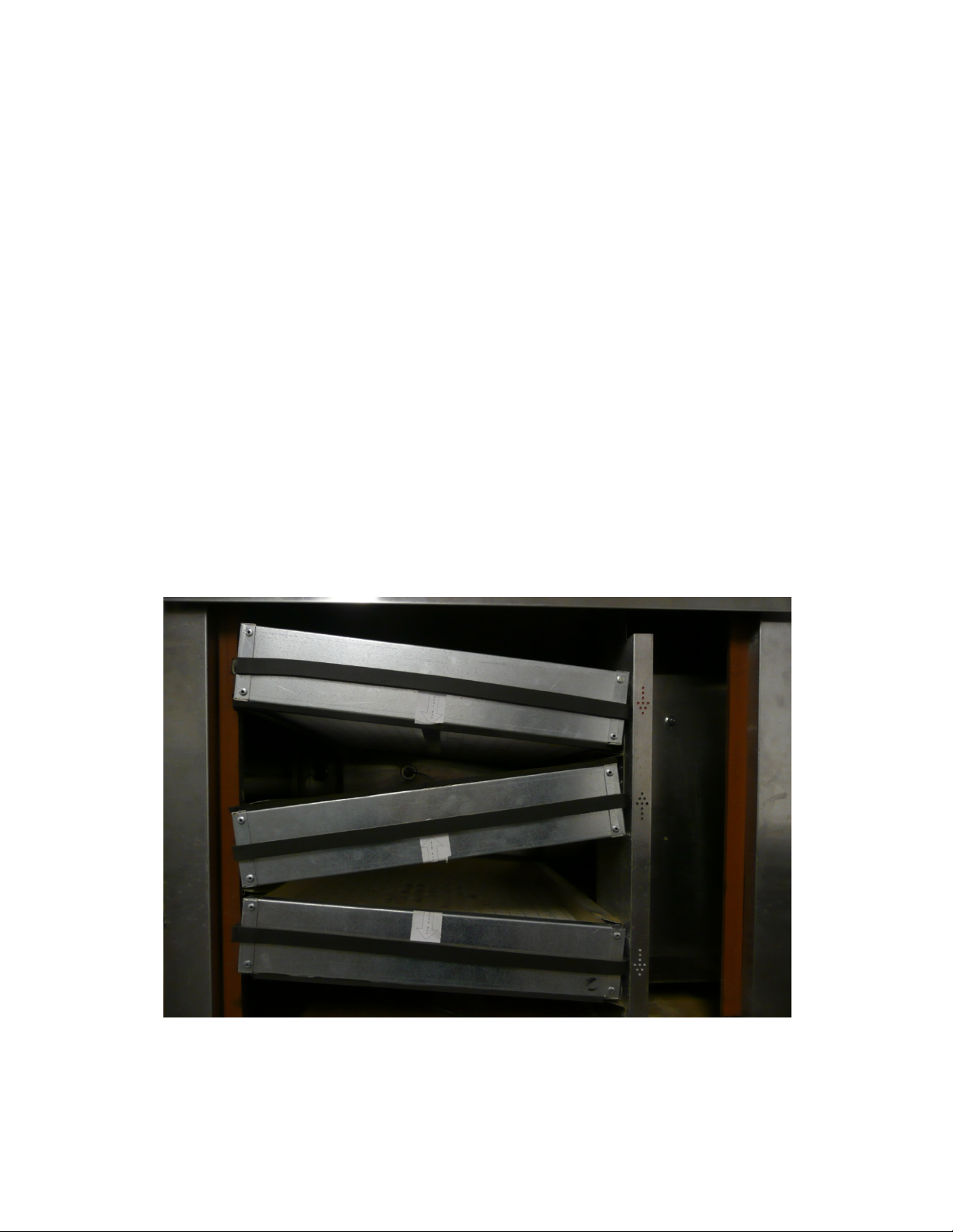
2. Filters have a airflow direction associated with them. Pre-filters should be installed so drains are
at the bottom edge of the filter. All other filters have an airflow direction sticker that must match
the direction of airflow. See the picture below for this illustration and filter part numbers.
3. All fasteners should be checked for tightness each time maintenance checks are performed prior
to restarting unit.
4. Ductwork and PCU should be cleaned according to code requirements.
Filter Information
NOTE FILTERS INSTALLED WITH DIRECTION ARROW STICKERS MATCHING DIRECTION
ARROW ON PCU FRAME
Page 18
18
Standard Filter Part Numbers
PCU
Module
Size
16” x 20” x 4”
20” x 25” x 4”
Steel Pre-Filter
High Efficiency (MERV 14)
Odor Control
Size 1 3
118-700-014
LG4-M-912-P
BPSL 31222
Size 2 8
118-700-011
LG4-M-909-P
BPSL 31224
Size 3 8
118-700-014
LG4-M-912-P
BPSL 31222
Size 4
15
118-700-011
LG4-M-909-P
BPSL 31224
Size 5 12
118-700-014
LG4-M-912-P
BPSL 31222
Size 6 18
118-700-014
LG4-M-912-P
BPSL 31222
Optional Pre-Filters, High Eff, and HEPA Filter Part Numbers
PCU
Module
Size
16 x 20 x 4
20 x 25 x 4
UL-1046 Pre-
Filter
Captrate
Solo Pre-
Filter
High Temperature High
Efficiency Filter
HEPA Part Number
Class 1
HEPA
Filter
Size 1 3
SSH2025
CSF2025-NH
110-500-404
H1924x22-0B8000036
2909329
Size 2 8
SSH2016
CSF2016-NH
110-500-405
H1519x22-0B8000036
2909332
Size 3 8
SSH2520
CSF2520-NH
110-500-404
H1924x22-0B8000036
2909329
Size 4
15 SSH2016
CSF2016-NH
110-500-405
H1519x22-0B8000036
2909332
Size 5 12
SSH2025
CSF2025-NH
110-500-404
H1924x22-0B8000036
2909329
Size 6 18
SSH2025
CSF2025-NH
110-500-404
H1924x22-0B8000036
2909329
Optional Odor Control Media Part Numbers
PCU
Module
Size
16 x 20 x 4
20 x 25 x 4
100% Carbon
100%
Permanganate
Caustic
Impregnated
Carbon /
Permanganate
Blend Panel
100%
Carbon
Panel
100%
Permanganate
Panel
Caustic
Impregnated
Panel
Size 1 3
BPSL 31231
BPSL 31226
BPSL 31229
B21711
B21709
B21712
B21710
Size 2 8
BPSL 31230
BPSL 31227
BPSL 31228
B21199
B21197
B21200
B21198
Size 3 8
BPSL 31231
BPSL 31226
BPSL 31229
B21711
B21709
B21712
B21710
Size 4
15
BPSL 31230
BPSL 31227
BPSL 31228
B21199
B21197
B21200
B21198
Size 5 12
BPSL 31231
BPSL 31226
BPSL 31229
B21711
B21709
B21712
B21710
Size 6 18
BPSL 31231
BPSL 31226
BPSL 31229
B21711
B21709
B21712
B21710
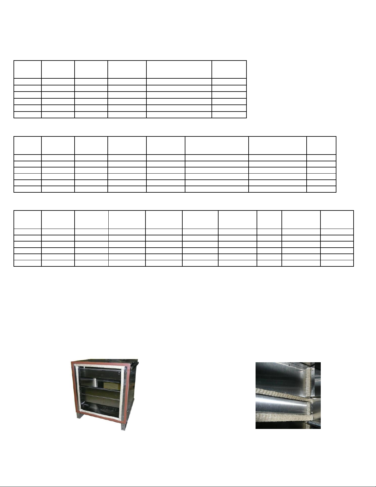
There are two types of gasket used in sealing the PCU. The orange gasket is used for weatherproofing
the exterior seams between modules. It is rated at 450° F and has a PSA backing. The white gasket is a
1500° F degree gasket that is used to seal all internal joints in the PCU, including the doors, filter tracks,
and inner perimeter between modules. Orange gasket is applied to the sides and White gasket is applied
at the top of the filter access area to prevent infiltration. There is a double layer of gaskets between
modules as shown below.
450° F Gasket between Modules and doors 1500° F Gasket for Internal Joints
Page 19

19
Gasket Type Chart
Gasket Type
Application
Size
Temp Rating
Part Number
High Temp Closed Cell (Orange)
Exterior Seam Between Modules
3/16” x 1”
450°F
SNS200A-1/4x1
High Temp Ceramic (White)
Internal Seams
¼” x 1”
1500°F
397-91PSA
2 Weeks After Startup
1. Inspect the unit and duct for grease or air leaks and repair leaks where required.
2. All fasteners and hardware should be checked for tightness each time maintenance checks are
performed prior to restarting unit.
3. Monitor filter loading and determine the frequency that filters should be replaced. This will vary
with the amount of contaminated effluent being filtered. Airflow will be effected (reduced) by filter
loading. It is important that the pre-filter be cleaned on a regular basis and that the remaining
filters be replaced when necessary to keep design airflow requirements.
4. Make necessary adjustments to air pressure switch to ensure proper function of indicator light.
Every Month
1. Inspect the unit and duct for grease or air leaks and repair leaks where required.
2. Filters need to be checked monthly for loading. If required, the filters either need to be cleaned or
replaced. Filter change out may occur more often in severe conditions. Washable steel prefilters can be washed in warm soapy water. When re-installing filters, be sure to install with the
airflow in the correct direction as indicated on the filter or with drain holes on bottom edge of
filter.
Duct Cleaning
1. Place tarp under PCU to catch overspray during cleaning.
2. Place tarp over Blower insulation and motor to prevent damage during cleaning.
3. Remove all tarps from Unit after cleaning is completed.
Yearly
1. Inspect all seals for wear and deterioration. Replace if necessary.
2. Inspect pre-filter for cleanliness. Replace if necessary.
3. Replace all secondary filtration and odor control media.
4. Inspect unit for leaks where ductwork is attached and in modules themselves. Repair where
necessary.
Page 20
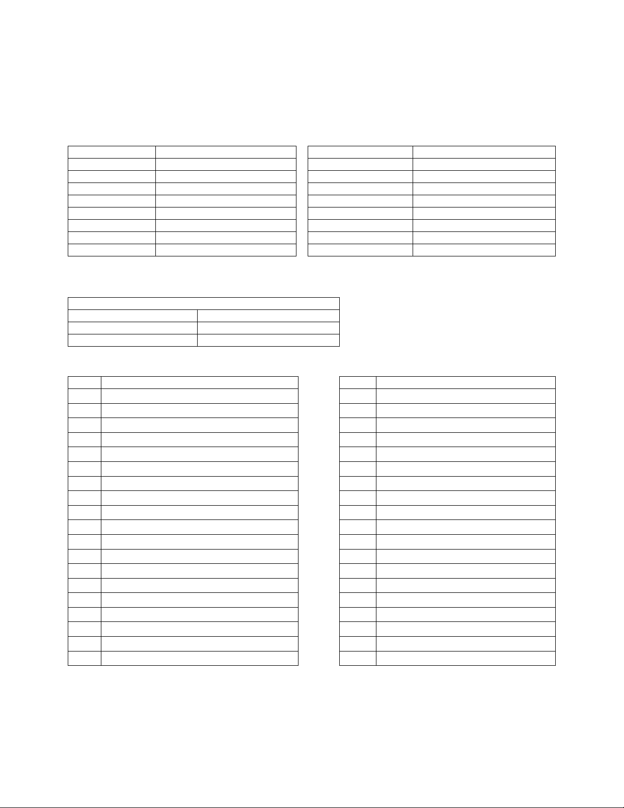
20
Start-Up and Maintenance Documentation
START-UP AND MEASUREMENTS SHOULD BE PERFORMED AFTER THE SYSTEM HAS BEEN
AIR BALANCED (Warranty will be void without completion of this form)
Job Information
Job Name
Service Company
Address
Address
City
City
State
State
Zip
Zip
Phone Number
Phone Number
Fax Number
Fax Number
Contact
Contact
Purchase Date
Start-Up Date
PCU Information
Refer to the start-up procedure in this manual to complete this section.
Name Plate and Unit Information
Model Number
Serial Number
Pressure Switch Set Point
Maintenance Record
Date
Service Performed
Date
Service Performed
Factory Service Department
Phone: 1-866-784-6900
Fax: 1-919-554-9374
 Loading...