


Demand Control Ventilation System
Installation, Operation, and Maintenance Manual
RECEIVING AND INSPECTION
Upon receiving unit, check for any interior and exterior damage, and if found, report it immediately to the carrier. Also check that all accessory items are accounted for and are damage free.
WARNING!!
Installation of this control panel should only be performed by a qualified professional who has read and understands these instructions and is familiar with proper safety precautions. Improper installation poses serious risk of injury due to electric shock and other potential hazards. Read this manual thoroughly before installing or servicing this equipment. ALWAYS disconnect power prior to working on module.
Save these instructions. This document is the property of the owner of this equipment and is required for future maintenance. Leave this document with the owner when installation or service is complete.
A0023662
May 2014 Rev. 5
TABLE OF CONTENTS
Demand Control Ventilation System ............................................................................................................. |
1 |
Installation, Operation, and Maintenance Manual ........................................................................................ |
1 |
WARRANTY.................................................................................................................................................. |
3 |
SAFETY INFORMATION .............................................................................................................................. |
4 |
General ................................................................................................................................................. |
4 |
Installation............................................................................................................................................. |
4 |
Control board (ECPM03) Technical Information .................................................................................. |
4 |
INSTALLATION............................................................................................................................................. |
6 |
Mechanical................................................................................................................................................ |
6 |
Site Preparation .................................................................................................................................... |
6 |
Assembly .............................................................................................................................................. |
6 |
Room Sensor Installation ..................................................................................................................... |
6 |
Utility Cabinet Installation (Typical) ...................................................................................................... |
6 |
Wall Mount Installation (Optional) ........................................................................................................ |
7 |
Duct Sensor Installation........................................................................................................................ |
7 |
Electrical ................................................................................................................................................... |
7 |
Copper Wire Ampacity.......................................................................................................................... |
8 |
High Voltage Wiring.............................................................................................................................. |
8 |
Low Voltage Wiring............................................................................................................................... |
9 |
Variable Frequency Drive (VFD) Installation Instructions .................................................................. |
10 |
OPERATION ............................................................................................................................................... |
12 |
Start-Up Procedure ................................................................................................................................. |
12 |
Sequence of Operation ........................................................................................................................... |
13 |
Functionality............................................................................................................................................ |
15 |
Fan Control ......................................................................................................................................... |
15 |
Preparation Time Mode ...................................................................................................................... |
15 |
Hood Lights ........................................................................................................................................ |
15 |
Electric Gas Valve Reset.................................................................................................................... |
15 |
High Temperature Automatic Appliance Shutdown ........................................................................... |
15 |
Make-Up Air Interlock ......................................................................................................................... |
15 |
Appliances Pilot Check Warning: ....................................................................................................... |
16 |
Building Management System (Dry Contact) ..................................................................................... |
16 |
Minimum Room Temperature............................................................................................................. |
16 |
Self-Cleaning (Optional) ..................................................................................................................... |
16 |
Fan Proving Interlock (Optional) (i.e. Loss of Load Interlock/Airflow Fault Interlock) ........................ |
17 |
CORE Protection Fire System (Optional) ........................................................................................... |
17 |
PCU Advanced Filter Monitoring (AFM) (Optional) ............................................................................ |
17 |
Electric Gas Valve Follow Fans (optional).......................................................................................... |
17 |
Shunt Trip Follow Fans (Optional)...................................................................................................... |
18 |
Dimmable HMI (Optional) ................................................................................................................... |
18 |
CO Sensor Input (Optional) ................................................................................................................ |
18 |
PCU CORE ONLY (Optional) ............................................................................................................. |
18 |
Energy Saving Graph (optional) ......................................................................................................... |
18 |
Configuration and Diagnostics................................................................................................................ |
19 |
Security............................................................................................................................................... |
19 |
Setup Options ..................................................................................................................................... |
19 |
Component Description............................................................................................................................... |
28 |
Variable Frequency Drive ................................................................................................................... |
28 |
ECPM03 board ................................................................................................................................... |
28 |
Temperature Sensor........................................................................................................................... |
30 |
Room Temperature Sensor ................................................................................................................ |
30 |
HMI ..................................................................................................................................................... |
30 |
Troubleshooting .......................................................................................................................................... |
31 |
MAINTENANCE .......................................................................................................................................... |
33 |
2 |
A0023662 |
|
May 2014 Rev.5 |
WARRANTY
This equipment is warranted to be free from defects in materials and workmanship, under normal use and service, for a period of 12 months from date of shipment. This warranty shall not apply if:
1.The equipment is not installed by a qualified installer per the MANUFACTURER’S installation instructions shipped with the product,
2.The equipment is not installed in accordance with federal, state and local codes and regulations,
3.The equipment is misused or neglected,
4.The equipment is not operated within its published capacity,
5.The invoice is not paid within the terms of the sales agreement.
The MANUFACTURER shall not be liable for incidental and consequential losses and damages potentially attributable to malfunctioning equipment. Should any part of the equipment prove to be defective in material or workmanship within the 12-month warranty period, upon examination by the MANUFACTURER, such part will be repaired or replaced by MANUFACTURER at no charge. The BUYER shall pay all labor costs incurred in connection with such repair or replacement. Equipment shall not be returned without MANUFACTURER’S prior authorization and all returned equipment shall be shipped by the BUYER, freight prepaid to a destination determined by the MANUFACTURER.
3 |
A0023662 |
|
May 2014 Rev.5 |

SAFETY INFORMATION
General
This control panel utilizes a mixture of traditional controls along with a “smart” digital circuit board controller, referred to as the ECPM03 control board. It is intended to be installed within a UL508A electrical control package. The board is powered by 24 Volts DC, which is provided by an approved 10-20 Watt class 2 power supply included inside the panel.
Some parts of the ECPM03 circuit board can be electrically live and some surfaces can be hot. Inappropriate use and incorrect installation or operation creates the risk of injury to personnel and/or damage to equipment. All operations concerning installation, commissioning and maintenance must be carried out by qualified, skilled person who is familiar with the installation, assembly, commissioning, and operation of the control panel and the application for which it is being used.
Installation
Ensure proper handling and avoid excessive mechanical stress. Do not bend any components during transport, handling, installation or maintenance. Do not touch any electronic components or contacts. This board contains electrostatically sensitive components, which can easily be damaged by inappropriate handling. Static control precautions must be adhered to during installation, testing, servicing and repairing of this board. Component damage may result if proper procedures are not followed.
To ensure proper operation, do not install the board where it is subjected to adverse environmental conditions such as combustible, oily, or hazardous vapors; corrosive chemicals; excessive dust, moisture or vibration; direct sunlight or extreme temperatures.
The ECPM03 may be mounted by means of DIN rail clips and board standoffs or by standoffs alone. It will be mounted in a NEMA 1 enclosure for indoor use only.
When working on live panel controllers, applicable national safety regulations must be observed. The electrical installation must be carried out according to the appropriate regulations (e.g. cable crosssections, circuit breaker, protective earth [PE] connection). While this document does make recommendations in regards to these items, national and local codes must be adhered to.
Control board (ECPM03) Technical Information
Ratings |
24VDC, 10-20Watts |
Other Ratings |
On-board relay contacts are 120VAC with 4Amps Max |
Flammability |
FR4 board with 94V0 flammability rating |
IP rating |
IPX0 |
Fuse on board |
Slo-Blo 4 Amp fuse, 5x20mm |
Humidity |
< 95% non-condensing |
Temperature range |
-10 to +55°C or +15 to +130 °F |
Battery |
Model 2032 - Lithium Coin Cell, 3VDC, 0.043mA |
Dimensions |
203mm L x 140mm W x 46mm H |
Weight |
0.6 lbs. |
4 |
A0023662 |
|
May 2014 Rev.5 |

FIELD WIRING: The following is for reference only. All 120 Volt AC field wiring is landed on terminal blocks, not on the board itself. See Installation section for details. Low voltage class 2 field wiring may be landed at J3, J4, J5, or J10 connectors only, as indicated by the panel labeling and installation schematic. Provision for spacing and routing of the field wiring is provided in the panel.
FACTORY WIRING:
The connectors below are intended to be used for factory wiring only by a UL508A panel shop: J7, J8, J9 are provided for the control of 120 Volt AC relays, contactors, solenoids and shunt trip breakers. Under no circumstances shall any lighting or motor loads be directly connected to these connectors.
J1, J2, J6, are reserved for low voltage class 2 factory wiring.
Control Board (ECPM03) diagram
5 |
A0023662 |
|
May 2014 Rev.5 |
INSTALLATION
It is imperative that this unit is installed and operated with the designed airflow and electrical supply in accordance with these manual and applicable codes. If there are any questions about any items, please call the service department at 1-866-784-6900 for warranty and technical support issues.
Mechanical
WARNING: DO NOT LIFT CONTROL BY WIRING COMPONENTS
Site Preparation
1.Provide clearance around installation site to safely install equipment into its final position.
Supports must adequately support equipment. Refer to manufacturer’s estimated weights.
2.Consider general service and installation space when locating unit.
Assembly
When the control panel is ordered in a utility cabinet installed on the hood, there is no mechanical assembly required by the installer. If the control panel is ordered as a wall mounted panel, the enclosure must be secured to a fixed wall near the exhaust hoods. Be certain to maintain adequate clearance from excessive heat sources such as appliances to prevent damage of the components.
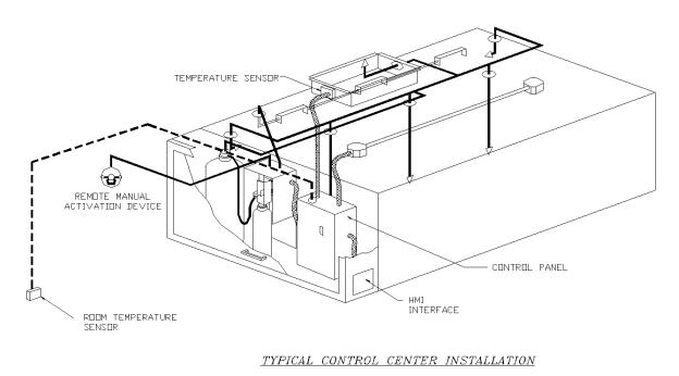
Room Sensor Installation
A room temperature sensor is provided with the panel. It should be installed in a safe location, free of influence from external heat sources. It should be indicative of the average kitchen temperature away from the appliances. The room sensor will always be landed at terminals T1A, T1B on the J10 connector of the ECPM03.
Utility Cabinet Installation (Typical)
6 |
A0023662 |
|
May 2014 Rev.5 |
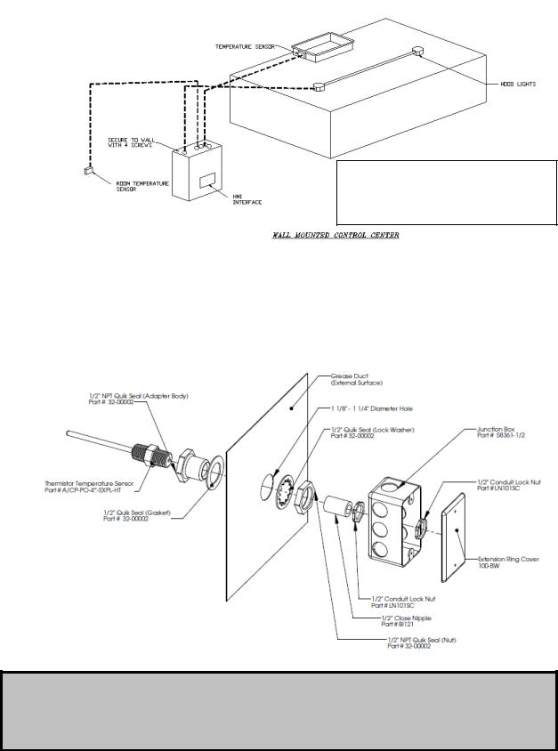
Wall Mount Installation (Optional)
Mount control panel with adequate clearance from excessive heat sources such as appliances to prevent damage of the components.
Duct Sensor Installation
When the control panel is ordered, the system typically consists of one duct sensor per hood exhaust riser. These sensors are typically shipped factory installed in factory assembled hood risers. If the risers are field cut, the sensor and other components are shipped loose for field installation as shown below. A hole must be cut in the grease duct, and the quick seal and sensor must be assembled as shown below. A 2-wire plenum rated thermistor cable (18 gauge typical), run in conduit, should be used to wire the sensors back to the controller and landed on connector J10 as indicated on the installation schematic.
IMPORTANT!!
When exhaust duct connections are located and cut in the field, duct temperature probes are shipped loose in the electrical package enclosure. These must be installed in the duct immediately above the hood for proper system operation.
7 |
A0023662 |
|
May 2014 Rev.5 |
Electrical
Before connecting power to the control, read and understand this entire document. As-built wiring diagrams are furnished with each control by the factory and are attached either to the door of the unit or provided within a paperwork pouch internal to the panel.
Electrical wiring and connections should be done in accordance with local ordinances and the National Electric Code, ANSI/NFPA70. Be sure the voltage and phase of the power supply and the wire amperage capacity is in accordance with the unit nameplate.
WARNING!! Disconnect power before installing or servicing control. High voltage electrical input is needed for this equipment. This work should be performed by a qualified electrician.
1. Always disconnect power before working on or near this |
Copper Wire Ampacity |
||
|
|
|
|
equipment. Lock and tag the disconnect switch or breaker |
|
Wire Size AWG |
Maximum Amps |
to prevent accidental power up. |
|
14 |
15 |
2. Make certain that the power source is compatible with the |
|
||
|
12 |
20 |
|
requirements of your equipment. The installation wiring |
|
||
|
10 |
30 |
|
schematic identifies the proper phase and voltage of the |
|
||
|
8 |
50 |
|
source breakers. |
|
||
|
6 |
65 |
|
3. Before connecting control to power source, verify power |
|
||
|
4 |
85 |
|
line wiring is de-energized. |
|
||
|
|
|
|
4.Secure all wiring to prevent contact with sharp objects.
5.Do not kink power cable and never allow the cable to come in contact with oil, grease, hot surfaces or chemicals.
6.Before powering up the system, make sure that the interior of the control is free of loose debris, metal shavings, or shipping materials. `
7.If any of the original wire supplied with the system must be replaced, it must be replaced with type THHN wire or equivalent.
High Voltage Wiring
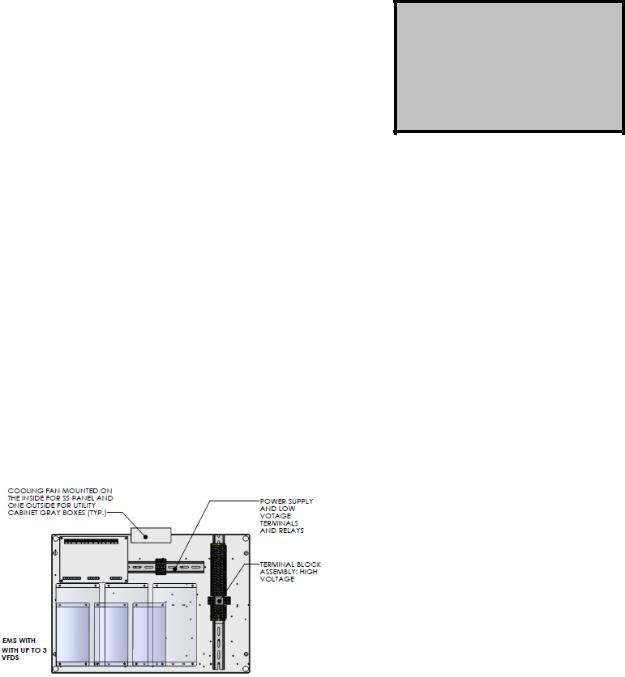
1. All high voltage wiring shall be terminated on the right side of the vertical terminal blocks located on the right hand side.
2. There are multiple electrical power sources required for this panel. Refer to Installation diagrams for details.
3. The hood light wiring will also need to be wired to terminals as indicated on the installation diagram.
4. If an ANSUL fire system is present, the fire system micro-switch will need to be wired to terminals as indicated on the installation diagram, typically “C1” and “AR1”. C1 is the common
and connects to terminal 1 on the micro-switch. AR1 is the armed state and connects to terminal 2 on the micro-switch. If a CORE fire system is present, this connection is not required.
8 |
A0023662 |
|
May 2014 Rev.5 |
Low Voltage Wiring
Low voltage field wiring consists of Duct and Room Temperature sensors, ECM motors, 0-10VDC output, 24VDC input, or Modbus communication over CAT-5 cables for HMI(s) and remote equipment. Additionally, panels can be ordered with Building Management Options. Refer to the Building
Management Owner’s Manual, if equipped, for low voltage building management wiring requirements.
Low voltage wiring must be run on the left hand side and directly terminated on the terminals located on the ECPM03 board.
WARNING: Low voltage wires should never be run together with high voltage wires.
1- Room temperature sensor(s): For all installations, at least 1 room temperature sensor must be installed in a safe location, free of influence from external heat sources. It should be indicative of the average kitchen temperature away from the appliances. 2-wire 18 AWG thermistor cable must be used. The room temperature sensor shall be wired according to the installation wiring schematic, terminals “T1A” and ”T1B”.
2- Duct temperature sensors: For all installations excluding a single hood with factory risers and a hood mounted panel, duct mounted temperature sensors will need to be wired in the field. 2-wire 18 AWG plenum rated thermistor cable must be used. The temperature sensor should be wired to terminal blocks as indicated on the installation wiring schematic.
3- HMI is connected to the ECPM03 board through a CAT-5 cable. The HMI has two RJ-45 connectors connected together for Modbus. The HMI connects to port J4 or J5 (RJ-45) of the ECPM03 board. The other RJ-45 port of the HMI will typically be occupied by a RJ-45 end-of-line terminator (Part # EOL120A).
4- Two end-of-line terminators (Part # EOL120A) are included in each panel. They are typically plugged in at the factory on J3 and either on port J4 or in the back of the first HMI. If another HMI or other equipment need to connect to a port occupied by an end-of-line terminator, it shall be removed and place on the HMI or equipment that became connected at the end of the Modbus network.
5- If other pieces of equipment such as PCU Advanced Filter Monitoring (AFM) are connected to this panel, a cat-5 cable will also be used to run the Modbus communication between these devices. The cable would be plugged in port J3 of the ECPM03 board. The end-of-line terminators should then be relocated from J3 to the PCU AFM module.
9 |
A0023662 |
|
May 2014 Rev.5 |
Variable Frequency Drive (VFD) Installation Instructions
Input AC Power
1.Circuit breakers feeding the VFDs are recommended to be thermal-magnetic and fast acting. They should be sized 1.25 to 1.5 times the input amperage of the drive. Refer to the installation schematic for breaker sizing.
2.Each VFD should be fed by its own breaker. If multiple VFDs are to be combined on the same breaker, each drive should have its own protection measure (fuses or miniature circuit breaker) downstream from the breaker.
3.Input AC line wires should be run in conduit from the breaker panel to the drives. AC input power to multiple VFDs can be run in a single conduit if needed.
4.The VFD should be grounded on the terminal marked PE.
STOP!
DO NOT connect incoming AC power to output terminals U, V, W. Severe damage to the drive will result. Input power must always be wired to the L terminal connections (L1, L2, L3)
Output Power
1.Motor wires from each VFD to its respective motor MUST be run in a separate steel conduit away from control wiring and incoming AC power wiring to avoid noise and crosstalk between drives.
2.Load reactors: If the distance between the VFD and the motor is great, a load reactor should be used between the VFD and the motor. The output reactor should be sized accordingly.
208/230V – Load reactor should be used when distance exceeds 250 feet. 460/480V – Load reactor should be ordered when distance exceeds 50 feet. 575V– Load reactor should be ordered when distance exceeds 25 feet.
3.If the distance between the VFD and the motor is between 500 and 1000 FT, a dV/dT filter should be used.
4.No contactor should be installed between the drive and the motor. Operating such a device while the drive is running can potentially cause damage to the power components of the drive.
5.When a disconnect switch is installed between the drive and motor, it should only be operated when the drive is in a STOP state.
Programming
Most VFD parameters are preprogrammed at the factory when proper information about the fan motors is provided. However the 2 parameters below should be verified in the field during startup.
1.The Drive should be programmed for the proper motor voltage. Refer to parameter P107 in the
“Component Description - Variable Frequency Drive” chapter below.
P107 is set to 0 (Low) if motor voltage is 120 VAC, 208 VAC or 400 VAC. P107 is set to 1 (High) if motor voltage is 230 VAC, 480 VAC or 575 VAC.
2.The Drive should be programmed for the proper motor overload value. Refer to parameter P108 in the “Component Description - Variable Frequency Drive” chapter below.
P108 is calculated as Motor FLA x 100 / Drive Output Rating (available in table below). P108 is
also indicated on the factory wiring schematic under the “Motor Power Circuit” column.
NOTE: Do NOT adjust minimum and maximum frequency on the VFD. Communication errors will result between the control board and the VFD. These parameters should be adjusted through the control panel only.
10 |
A0023662 |
|
May 2014 Rev.5 |
ACTECH SMV VFD CROSS-REFERENCE TABLE
|
|
|
|
|
Input |
Input |
|
|
|
|
|
|
|
|
Amps |
Amps |
|
Breaker |
Breaker |
|
|
1Ø |
3Ø |
|
1Ø |
1Ø |
Output |
1Ø |
1Ø |
Model Number |
Volts |
input |
input |
HP |
120VAC |
240VAC |
Amps |
120VAC |
240VAC |
|
120/ |
|
|
|
|
|
|
|
|
ESV751N01SXB571 |
240V |
X |
|
1 |
16.6 |
8.3 |
4.2 |
25 |
15 |
|
120/ |
|
|
|
|
|
|
|
|
ESV112N01SXB571 |
240V |
X |
|
1.5 |
20 |
10 |
6 |
30 |
20 |
|
|
|
|
|
Input |
Input |
|
|
|
|
|
|
|
|
Amps |
Amps |
|
Breaker |
Breaker |
|
|
|
|
|
1Ø |
3Ø |
|
1Ø |
3Ø |
ESV371N02YXB571 |
240V |
X |
X |
0.5 |
5.1 |
2.9 |
2.4 |
15 |
15 |
ESV751N02YXB571 |
240V |
X |
X |
1 |
8.8 |
5 |
4.2 |
15 |
15 |
ESV112N02YXB571 |
240V |
X |
X |
1.5 |
12 |
6.9 |
6 |
20 |
15 |
ESV152N02YXB571 |
240V |
X |
X |
2 |
13.3 |
8.1 |
7 |
25 |
15 |
ESV222N02YXB571 |
240V |
X |
X |
3 |
17.1 |
10.8 |
9.6 |
30 |
20 |
ESV402N02TXB571 |
240V |
|
X |
5 |
|
18.6 |
16.5 |
|
30 |
ESV552N02TXB571 |
240V |
|
X |
7.5 |
|
26 |
|
|
|
|
|
23 |
|
40 |
|||||
ESV752N02TXB571 |
240V |
|
X |
10 |
|
33 |
|
|
|
|
|
29 |
|
50 |
|||||
ESV113N02TXB531 |
240V |
|
X |
15 |
|
48 |
|
|
|
|
|
42 |
|
80 |
|||||
ESV153N02TXB531 |
240V |
|
X |
20 |
|
59 |
54 |
|
90 |
|
|
|
|
|
|
|
|
|
|
ESV751N04TXB571 |
480V |
|
X |
1 |
|
2.5 |
2.1 |
|
15 |
ESV112N04TXB571 |
480V |
|
X |
1.5 |
|
3.6 |
3 |
|
15 |
ESV152N04TXB571 |
480V |
|
X |
2 |
|
4.1 |
|
|
|
|
|
3.5 |
|
15 |
|||||
ESV222N04TXB571 |
480V |
|
X |
3 |
|
5.4 |
|
|
|
|
|
4.8 |
|
15 |
|||||
ESV402N04TXB571 |
480V |
|
X |
5 |
|
9.3 |
8.2 |
|
15 |
ESV552N04TXB571 |
480V |
|
X |
7.5 |
|
12.4 |
11 |
|
20 |
ESV752N04TXB571 |
480V |
|
X |
10 |
|
15.8 |
|
|
|
|
|
14 |
|
25 |
|||||
ESV113N04TXB531 |
480V |
|
X |
15 |
|
24 |
|
|
|
|
|
21 |
|
40 |
|||||
ESV153N04TXB531 |
480V |
|
X |
20 |
|
31 |
27 |
|
50 |
ESV183N04TXB531 |
480V |
|
X |
25 |
|
38 |
34 |
|
60 |
ESV223N04TXB531 |
480V |
|
X |
30 |
|
45 |
40 |
|
70 |
|
|
|
|
|
|
|
|
|
|
ESV751N06TXB571 |
600V |
|
X |
1 |
|
2 |
1.7 |
|
15 |
ESV152N06TXB571 |
600V |
|
X |
2 |
|
3.2 |
2.7 |
|
15 |
ESV222N06TXB571 |
600V |
|
X |
3 |
|
4.4 |
|
|
|
|
|
3.9 |
|
15 |
|||||
ESV402N06TXB571 |
600V |
|
X |
5 |
|
6.8 |
6.1 |
|
15 |
ESV552N06TXB571 |
600V |
|
X |
7.5 |
|
10.2 |
9 |
|
20 |
ESV752N06TXB571 |
600V |
|
X |
10 |
|
12.4 |
11 |
|
20 |
ESV113N06TXB531 |
600V |
|
X |
15 |
|
19.7 |
|
|
|
|
|
17 |
|
30 |
|||||
ESV153N06TXB531 |
600V |
|
X |
20 |
|
25 |
|
|
|
|
|
22 |
|
40 |
|||||
ESV183N06TXB531 |
600V |
|
X |
25 |
|
31 |
27 |
|
50 |
ESV223N06TXB531 |
600V |
|
X |
30 |
|
36 |
32 |
|
60 |
11 |
A0023662 |
|
May 2014 Rev.5 |
 Loading...