

Page 1
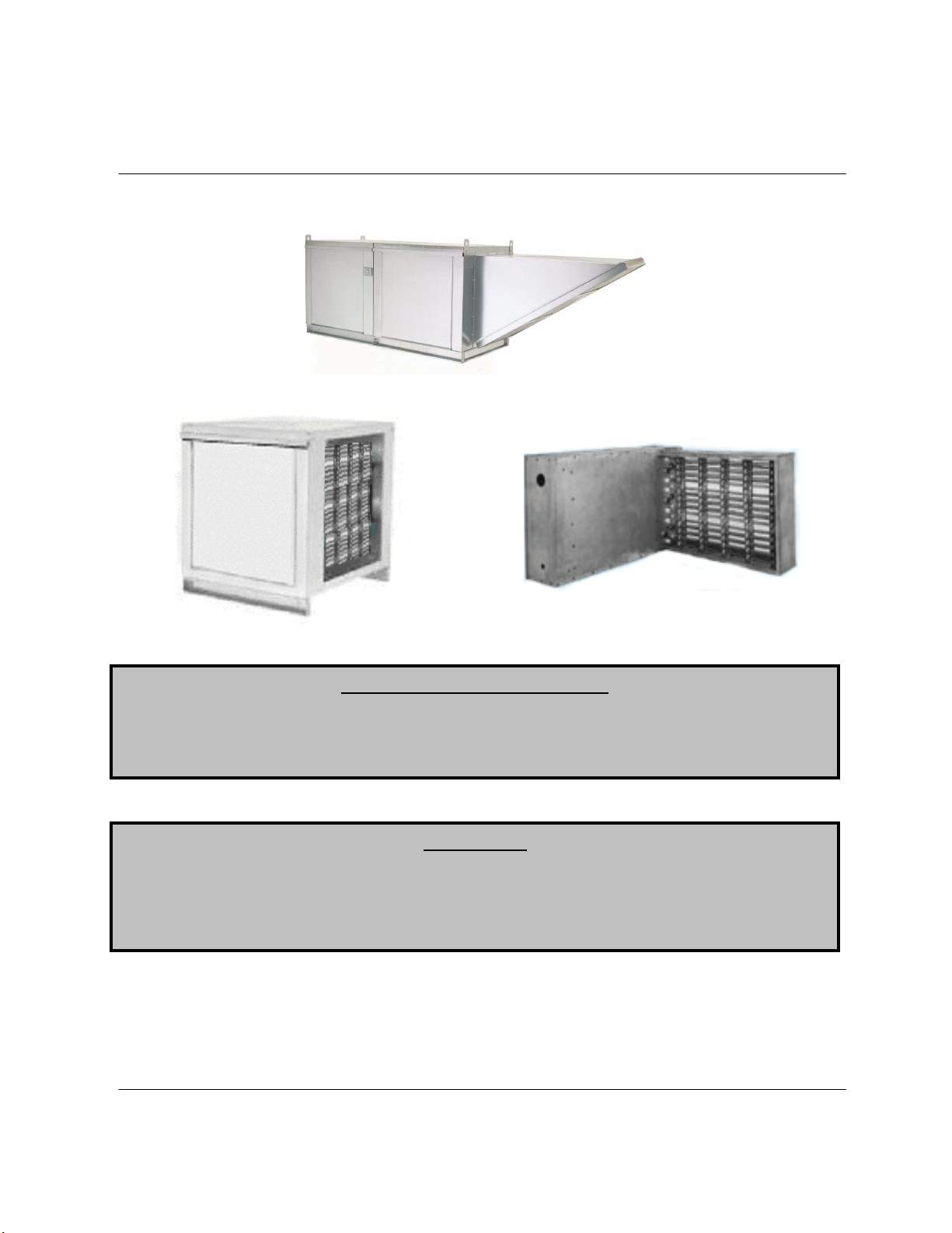
Standard and Modular Electric Heaters and Inserts
Installation, Operation, and Maintenance Manual
Modular Electric Heater
Electric Heat Module
Electric Duct Insert
Save these instructions
RECEIVING AND INSPECTION
WARNING!!
Upon receiving unit, check for any interior and exterior damage, and if found, report it
immediately to the carrier. Also check that all accessory items are accounted for and are
damage free. Turn the blower wheel by hand to verify free rotation and check the damper (if
supplied) for free operation.
Installation of this ventilator should only be performed by a qualified professional who has
read and understands these instructions and is familiar with proper safety precautions.
Improper installation poses serious risk of injury due to electric shock, contact with rotating
equipment and other potential hazards. Read this manual thoroughly before installing or
servicing this equipment. ALWAYS disconnect power prior to working on fan.
. This document is the property of the owner of this equipment and is
required for future maintenance. Leave this document with the owner when installation or
service is complete.
A0011031
April 2011 Rev. 13
Page 2

Page 3

TABLE OF CONTENTS
WARRANTY .................................................................................................................................................. 4
INSTALLATION ............................................................................................................................................. 5
Mechanical ................................................................................................................................................ 5
Site Preparation .................................................................................................................................... 5
Intake Assembly ................................................................................................................................... 5
Curb and Ductwork ............................................................................................................................... 5
Recommended Supply Ductwork Sizes ............................................................................................... 5
Roof Mount Installation ......................................................................................................................... 6
Installation with Exhaust Fan ................................................................................................................ 6
Duct Mount Installation ......................................................................................................................... 7
Indoor (INLINE) Installation .................................................................................................................. 7
Heat Module Add-On Installation ......................................................................................................... 7
Electrical ................................................................................................................................................... 8
Copper Wire Ampacity ......................................................................................................................... 8
PSC (Permanent Split Capacitor) Motor Speed Control ...................................................................... 9
ECM (Electronically Controlled Motor) Speed Control ......................................................................... 9
Motorized Intake Damper ..................................................................................................................... 9
Remote Control Panel ........................................................................................................................ 10
Fan to Building Wiring Connection ..................................................................................................... 10
OPERATION ............................................................................................................................................... 11
Start Up ................................................................................................................................................... 11
Special Tools Required ...................................................................................................................... 11
Start Up Procedure ............................................................................................................................. 11
Pulley Adjustment ............................................................................................................................... 12
Pulley Alignment ................................................................................................................................. 12
Proper Belt Tension ............................................................................................................................ 12
Pulley Setscrew Torque ..................................................................................................................... 12
Pulley Combination Chart ................................................................................................................... 13
Sequence of Operation ........................................................................................................................... 14
Main Circuit ......................................................................................................................................... 14
Optional Remote Panel Circuit ........................................................................................................... 15
Components............................................................................................................................................ 16
Remote Panel Option ......................................................................................................................... 17
Modulating Coil Thermostat Dip Switch Settings ............................................................................... 18
Step Controller Coil Thermostat Dip Switch Settings ......................................................................... 18
Troubleshooting ...................................................................................................................................... 19
Troubleshooting Chart ........................................................................................................................ 19
Remote Panel Troubleshooting Chart ................................................................................................ 20
MAINTENANCE .......................................................................................................................................... 21
General Maintenance ............................................................................................................................. 21
2 weeks after startup .............................................................................................................................. 21
Every 3 months ....................................................................................................................................... 22
Filter Quantity Chart ........................................................................................................................... 22
Yearly ...................................................................................................................................................... 22
Start-Up and Maintenance Documentation ............................................................................................ 24
Job Information ................................................................................................................................... 24
Heater Information .............................................................................................................................. 24
Maintenance Record .......................................................................................................................... 24
Factory Service Department ............................................................................................................... 24
3
Page 4

WARRANTY
This equipment is warranted to be free from defects in materials and workmanship, under normal use and
service, for a period of 12 months from date of shipment. This warranty shall not apply if:
1. The equipment is not installed by a qualified installer per the MANUFACTURER’S installation
instructions shipped with the product,
2. The equipment is not installed in accordance with federal, state and local codes and regulations,
3. The equipment is misused or neglected,
4. The equipment is not operated within its published capacity,
5. The invoice is not paid within the terms of the sales agreement.
The MANUFACTURER shall not be liable for incidental and consequential losses and damages
potentially attributable to malfunctioning equipment. Should any part of the equipment prove to be
defective in material or workmanship within the 12-month warranty period, upon examination by the
MANUFACTURER, such part will be repaired or replaced by MANUFACTURER at no charge. The
BUYER shall pay all labor costs incurred in connection with such repair or replacement. Equipment shall
not be returned without MANUFACTURER’S prior authorization and all returned equipment shall be
shipped by the BUYER, freight prepaid to a destination determined by the MANUFACTURER.
4
Page 5

INSTALLATION
It is imperative that this unit is installed and operated with the designed airflow and electrical supply in
accordance with this manual. If there are any questions about any items, please call the service
department at 1-866-784-6900 for warranty and technical support issues.
Mechanical
WARNING: DO NOT RAISE VENTILATOR BY THE INTAKE HOOD, BLOWER,
MOTOR SHAFT OR BEARINGS – USE LIFTING LUGS PROVIDED OR A SLING
Site Preparation
1. Provide clearance around installation site to safely rig and lift equipment into its final position.
Supports must adequately support equipment. Refer to manufacturer’s estimated weights.
2. Consider general service and installation space when locating unit.
3. Locate unit close to the space it will serve to reduce long, twisted duct runs.
4. Do not allow air intake to face prevailing winds. Support unit above ground or at roof level high
enough to prevent precipitation from being drawn into its inlet. The inlet must also be located at
least 10 feet away from any exhaust vents. The heater inlet shall be located in accordance with
the applicable building code provisions for ventilation air.
Intake Assembly
Intakes are shipped on a separate skid. Upon unit arrival, follow the following procedure to assemble the
intake to the fan
1. Apply silicone or weather-proof gasket on
the back side of the flanges of the intake
hood or v-bank intake.
2. Screw the flanges of the intake hood to the
unit with the supplied sheet metal screws.
Place caulk on the outside of the screws to
prevent water leaks. If the unit is a modular
unit with a v-bank or evaporative cooler
section, the v-bank or evaporative cooler will
bolt to the heater with the bolts provided.
Curb and Ductwork
This fan was specified for a specific CFM and static pressure. The ductwork attached to this unit will
significantly affect the airflow performance. Flexible ductwork and square elbows should not be used.
Also, transitions and turns in ductwork near the fan outlet will cause system effect and will drastically
increase the static pressure and reduce airflow. The chart below shows the minimum fan outlet duct
sizes and straight lengths recommended for optimal fan performance. Follow SMACNA guides and
recommendations for the remaining duct run. Fans designed for rooftop installation should be
installed on a prefabricated or factory built roof curb. Follow curb manufacturer’s instructions for proper
curb installation. The unit should be installed on a
curb and/or rail elevated not less than 20” above
any surface. Be sure duct connection and fan
outlet are properly aligned and sealed. Secure fan
to curb through vertical portion of the ventilator
base assembly flange using a minimum of eight
(8) lug screws, anchor bolts, or other suitable
fasteners (not furnished). Shims may be required
Recommended Supply Ductwork Sizes
Blower Size Duct Size Straight Duct Length
10 14 x 14 48 in.
15 20 x 20 72 in.
18 24 x 24 86 in.
20 26 x 26 108 in.
25 32 x 32 168 in.
5
Page 6
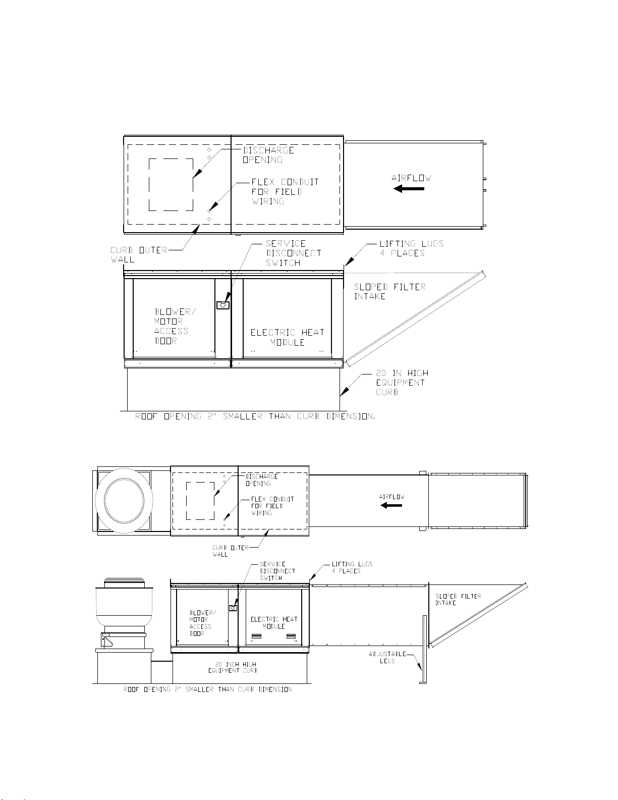
depending upon curb installation and roofing material. Check all fasteners for tightness. The diagrams
below show different mechanical installation configurations.
Roof Mount Installation
Installation with Exhaust Fan
6
Page 7
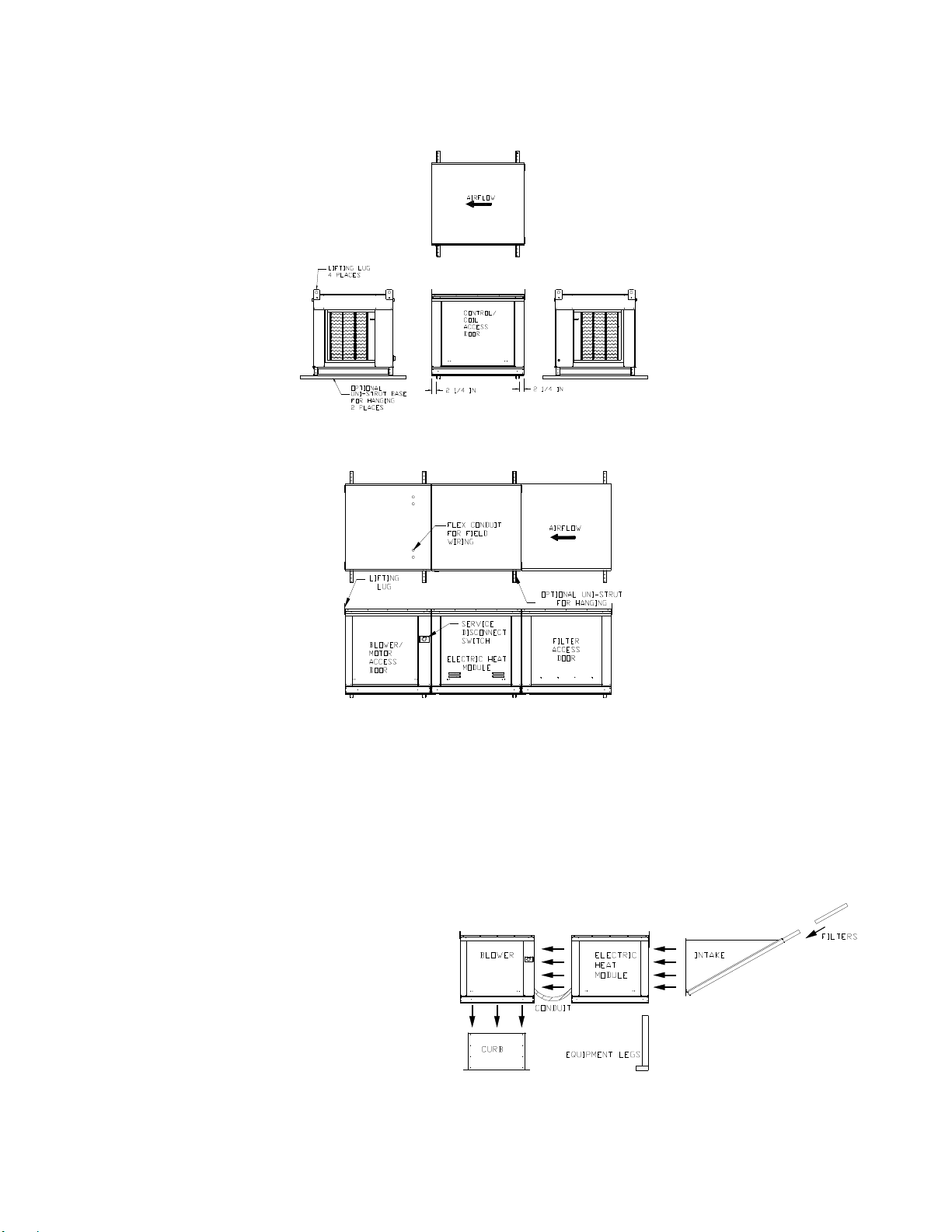
Duct Mount Installation
Indoor (INLINE) Installation
Heat Module Add-On Installation
Modular heat units shipped to add heat onto existing blower only applications require field mechanical
and wiring installation.
1. Remove existing filter intake and lifting lugs from blower section intake side.
2. Attach heat module to blower intake using the provided sheet metal screws and bolts. Tighten
screws and bolts securely to compress the gasket between the heat module and the blower
module.
3. Support and level the end of the heat
module (end opposite the blower) with
the provided equipment legs/rails.
4. Attach the filter hood to the intake side
of the heater module.
5. Drill a hole in the discharge of the
blower large enough to insert the
discharge control thermostat (if
provided). Install the sensor in the
drilled hole.
6. Wire the sensor and coil as indicated
on the supplied wiring schematic. Run
all wiring within metal conduit.
7
Page 8
Copper Wire Ampacity
Electrical
WARNING!!
Before connecting power to the heater, read and understand
this entire section of this document. As-built wiring diagrams
are furnished with each fan by the factory, and are attached to
the door of the unit.
Electrical wiring and connections should be done in accordance
with local ordnances and the National Electric Code,
ANSI/NFPA70. Be sure the voltage and phase of the power
Disconnect power before
installing or servicing fan. High
voltage electrical input is
needed for this equipment. This
work should be performed by a
qualified electrician.
supply and the wire amperage capacity is in accordance with
the motor nameplate. For additional safety information refer to AMCA publication 410-96, Recommended
Safety Practices for Users and Installers of Industrial and Commercial Fans.
WARNING: ELECTRIC HEATERS HAVE TWO POWER INPUTS. THE EXTERNAL
DISCONNECT INTERRUPTS POWER TO THE MOTOR AND CONTROLS ONLY.
THE ELECTRIC COIL POWER IS INTERRUPTED BY THE DISCONNECT SWITCH
ON THE ELECTRIC COIL DOOR.
1. Always disconnect power before working on or near a
heater. Lock and tag the disconnect switch or breaker to
prevent accidental power up.
2. An electrical drop containing the motor power wiring is
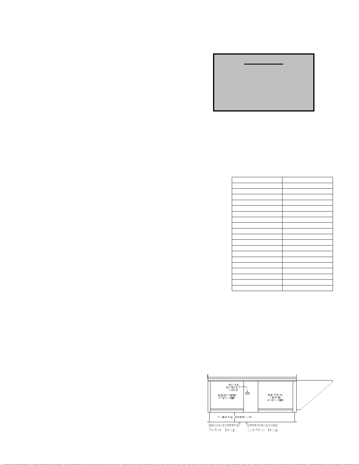
shipped with every fan. The electrical drop should be brought
through one of the conduit openings located in the base of the
unit, run through the curb, and connected to a junction box
inside the building.
3. A dedicated branch circuit should supply the motor circuit with
short circuit protection according to the National Electric Code.
This dedicated branch should be run to the junction box
mentioned above and connected as shown in a following
illustration labeled “Fan to Building Wiring Connection”.
4. A separate power source should supply the electric coil
power. Power from the building breaker should be wired
directly to the coil disconnect. This should be done using wire
of the proper gauge as indicated on the wire ampacity chart to
Wire Size AWG Maximum Amps
14 15
12 20
10 30
8 50
6 65
4 85
3 100
2 115
1 130
1/0 150
2/0 175
3/0 200
4/0 230
250 255
300 285
350 310
400 335
500 380
600 420
the right. A hole must be drilled in the fan enclosure to
properly run the electric coil power.
5. Make certain that the power source is compatible with the requirements of your equipment. The
heater nameplate identifies the proper phase and voltage of the motor and coil.
6. Units shipped with an optional remote panel have two electrical circuit drops. It is important to
run the motor wires in a separate conduit from the remote control wiring. The DC wires from the
unit temperature controller, located in the control drop, should be shielded cable or run in a
separate conduit.
7. Before connecting heater to the building power source, verify power line wiring is de-energized.
8. Secure the power cables to prevent contact with sharp objects.
9. Do not kink power cable and never allow the cable to come in contact with oil, grease, hot
surfaces or chemicals.
10. Before powering up the heater, check fan wheel for
free rotation and make sure that the interior of the
heater is free of loose debris or shipping materials.
11. If any of the original wire supplied with the heater
must be replaced, it must be replaced with type
THHN wire or equivalent.
8
Page 9
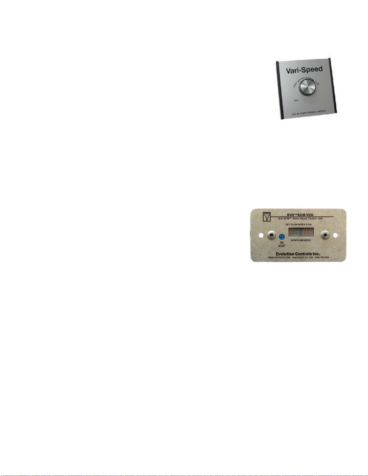
PSC (Permanent Split Capacitor) Motor Speed Control
Some single phase direct drive fans contain speed controls that regulate the
amount of voltage going to the motor. Specific PSC motors must be used in
conjunction with speed controls. The speed control has a knob with an off position,
and high to low range. At high speed, the speed control allows all of the line
voltage to pass right to the motor.
A minimum speed adjustment is provided to allow independent control of the
minimum speed setting. Minimum speed adjustment ensures motor runs with
sufficient torque to prevent stalling. To adjust this:
1) Motor must be in actual operating conditions to achieve proper speed
adjustment. Motor will not slow down unless proper load is applied.
2) Turn main control knob to lowest speed position.
3) Locate and adjust minimum speed setting and adjust with small screw driver. This can be found
under the speed control faceplate. (rotate clockwise to decrease minimum speed; counterclockwise to increase minimum speed).
4) Motor will now operate from this preset minimum speed to full speed.
The lowest minimum voltage that may be applied to these motors is 65VAC. Running lower
voltages to the motor can cause premature failure and overheating problems.
ECM (Electronically Controlled Motor) Speed Control
ECM motors and control allows accurate manual adjustment of fan speed.
The benefit of ECM motors is exceptional efficiency, performance, and
motor life.
The control used with ECM motors features a 4 digit LED numerical
display. The blue knob on the control allows the user to set the flow index
with a screwdriver. Twenty seconds later, the display shows the motor
RPM. Then, the display periodically alternates between the flow index and
motor RPM. The flow index has a range of 0 to 100% and is typically linear with motor RPM.
The ECM control requires a 24 VAC input and can locally turn the motor on and off. The motor can be
adjusted between 300 RPM and maximum speed with this control.
NOTE: To adjust the speed of 3 phase direct drive motors, a variable frequency
drive is required.
Motorized Intake Damper
On units shipped with the optional motorized intake damper, a power transformer is supplied with the unit
if the main incoming voltage is greater than 120V. The damper motor is automatically energized when
the main disconnect switch is in the ON position. No external wiring to the damper motor is required.
9
Page 10
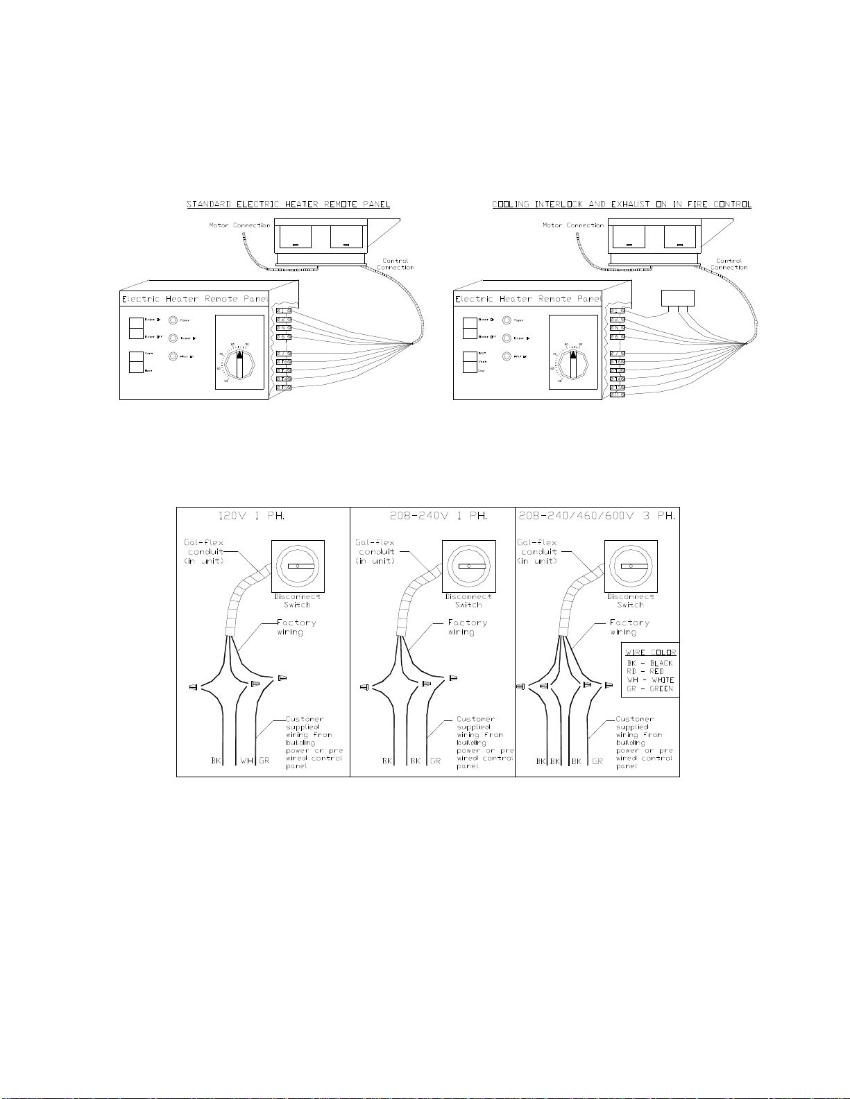
Remote Control Panel
On units shipped with the optional remote control panel, an electrical drop containing the panel wiring is
provided with the heater. There is a terminal strip inside the remote panel that matches the terminals in
the heater unit. The remote panel should be wired as shown below.
Fire System
Microswitch
NOCNC
BK
BK
OR
WH
GY
RD
BR
RD
YW
PK
BK
OR
WH
GY
RD
BR
RD
YW
PK
BL
PR
1
E
Fan to Building Wiring Connection
10
Page 11

OPERATION
Prior to starting up or operating the heater, check all fasteners for tightness. In particular, check the set
screw in the wheel hub, bearings and the fan sheaves (pulleys). With power to the heater OFF or prior to
connecting ventilator to power, turn the fan wheel by hand to be sure it is not striking the inlet or any
obstacles. Re-center if necessary.
Start Up
Special Tools Required
• AC Voltage Meter
• Tachometer
• Thermometer
Start Up Procedure
1. Check all electrical connections for tightness and continuity.
2. Check pulley alignment and belt tension as described below.
3. Inspect the condition of the intake damper and damper linkage, if provided.
4. Inspect the air-stream for obstructions and install intake filters if missing.
5. Compare the supplied motor voltage with the fan’s nameplate motor voltage. If this does not
match, correct the problem.
6. Compare the supplied coil voltage with the coil’s nameplate voltage. If this does not match,
correct the problem. If this does match, turn the coil disconnect to the ON position.
7. Start the fan up, by turning the external disconnect to the ON position, and shut it OFF
immediately to check rotation of the wheel with the directional arrow on the blower scroll.
Reversed rotation will result in poor air performance, motor overloading and possible burnout.
For units equipped with a single-phase motor check the motor wiring diagram to change rotation.
For 3-phase motors, any two power leads can be interchanged to reverse motor direction.
8. When the fan is started up, observe the operation and check for any unusual noises.
9. Switch the external disconnect back to the ON position and with the air system in full operation
and all ducts attached, measure the system airflow. Motor sheave (pulley) is variable pitch, and
allows for an increase or decrease of the fan RPM to adjust the airflow, as shown in the
illustration below. For your convenience, a RPM chart is included in the following pages.
10. Once the proper airflow is achieved, measure and record the fan speed with a reliable
tachometer. Caution - Excessive speed will result in motor overloading or bearing failure.
Do not set fan RPMs higher than specified in the maximum RPM chart. See the
troubleshooting guide for more information.
11. Measure and record the voltage and amperage to the motor and compare with the motor
nameplate to determine if the motor is operating under safe load condition.
12. Once the rpm of the ventilator has been properly set, disconnect power and recheck belt tension
and pulley alignment as described below.
13. Measure and record the voltage and amperage to the electric coil and compare with the coil
nameplate to determine if the coil is operating under safe load condition. While the blower is
operating, configure the thermostat for supply temperature control and disconnect one wire from
the discharge air sensor or thermostat. The amp draw and voltage should be measured in the
override condition to verify proper coil operation at max amperage. Reconnect all wires and dip
switches to original stat.
14. Verify that the coil thermostat is operating properly. Turn the thermostat dial to a set-point
warmer than the outside air temperature (if possible). With the blower running, the coil should
become energized and begin to heat the air. Once the thermostat becomes satisfied, the coil
should cycle off or reduce the number of energized heating stages. Turn the set-point below the
outside air temperature (if the climate permits), and the electric coil should cycle off. Set the
thermostat set-point to the desired setting to control either discharge air temperature or space
temperature (depending on how the unit was ordered).
• Amperage Meter
• Standard Hand Tools
11
Page 12
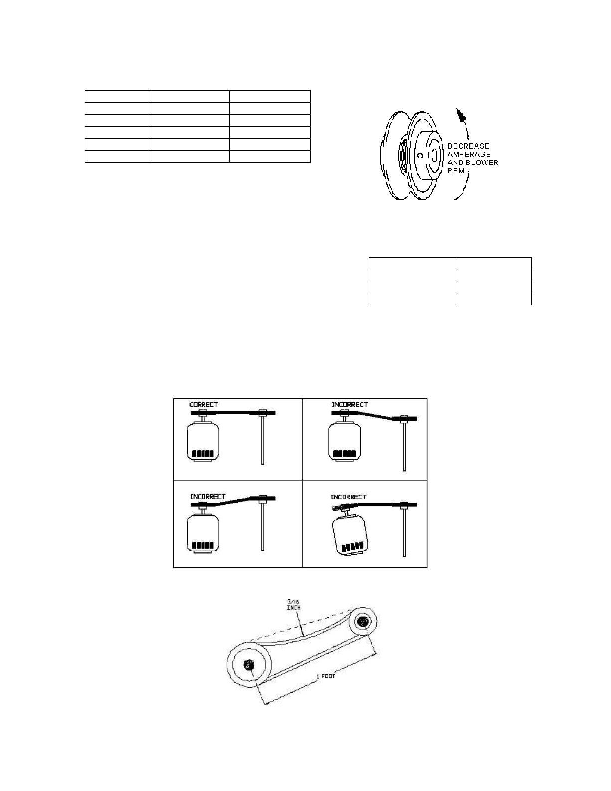
Maximum RPM and HP Chart
Pulley Adjustment Illustration
Blower Size Maximum RPM Maximum HP
10” 1800 2
15” 1400 5
18” 1200 5
20” 1000 10
25” 900 20
Pulley Adjustment
The adjustable motor pulley is factory set for the RPM specified.
Speed can be increased by closing or decreased by opening the
adjustable motor sheave. Two groove variable pitch pulleys
must be adjusted an equal number of turns open or closed. Any
increase in speed represents a substantial increase in
horsepower required by the unit. Motor amperage should always
be checked to avoid serious damage to the motor when the
speed is varied. Always torque setscrews according to the
setscrew torque chart.
Pulley Alignment
Pulley Setscrew Torque
Thread Size Torque (IN/Lb)
No. 10 (bushing) 32
1/4” (bushing) 72
5/16” 130
Proper Belt Tension
12
Page 13
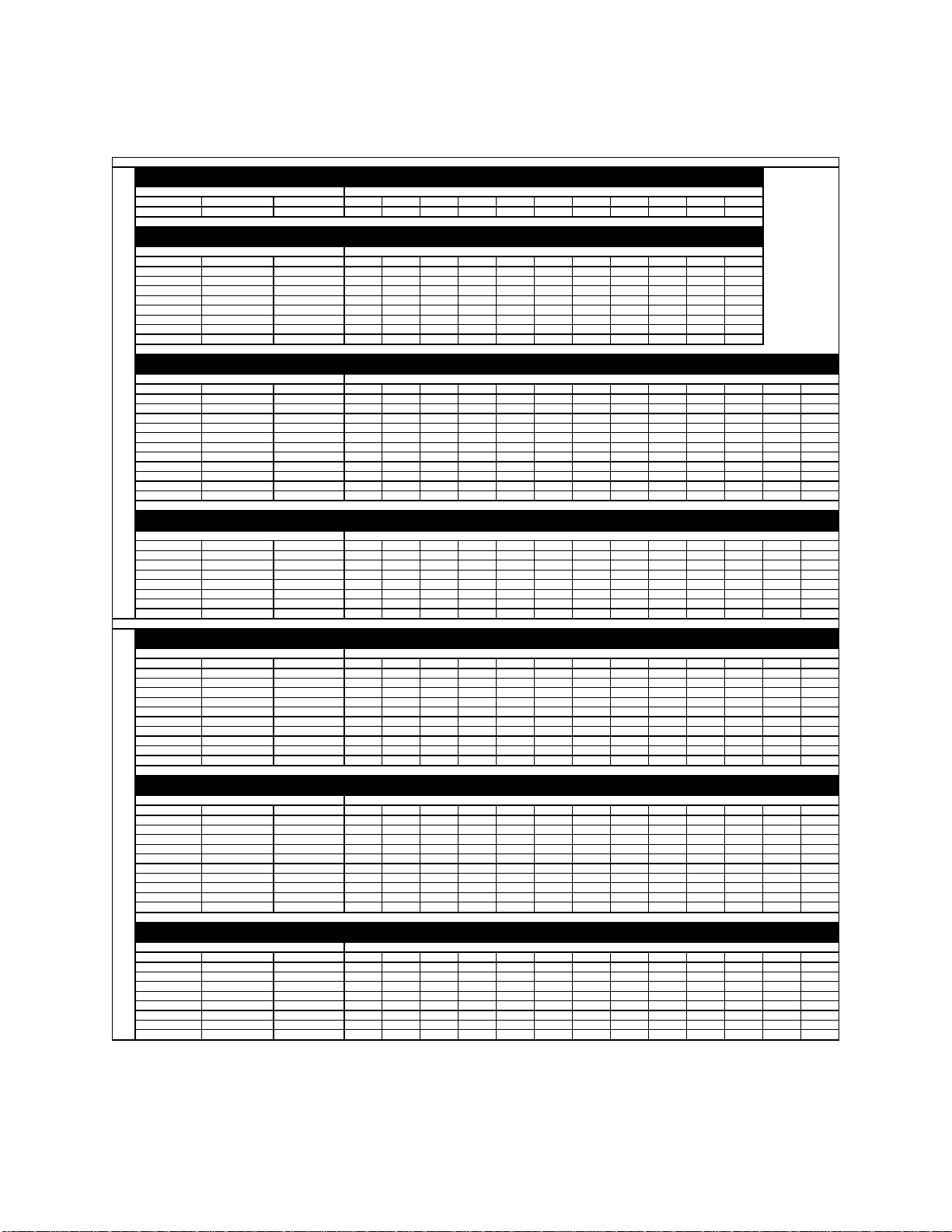
Pulley Combination Chart
** 2HP Motors on 20 IN Blowers use 2VP42 Pulleys
Motor RPM 1725
1/3 to 1-1/2 HP MOTOR PULLEY Dd1 Dd2 Pd1 Pd2
AX BELTS 1VL34 1.9 2.9 2 3
BLOWER PULLEY DATUM DIAMETER PITCH DIAMETER 5 4 1/2 4 3 1/2 3 2 1/2 2 1 1/2 1 1/2 0
AK114 11 11.2 308 323 339 354 370 385 400 416 431 447 462
1/3 to 2 HP MOTOR PULLEY Dd1 Dd2 Pd1 Pd2
AX BELTS 1VL40 2.4 3.4 2.6 3.6
BLOWER PULLEY DATUM DIAMETER PITCH DIAMETER 5 4 1/2 4 3 1/2 3 2 1/2 2 1 1/2 1 1/2 0
AK114 11 11.2 400 416 431 44 7 462 477 493 508 524 539 554
AK94 9 9.2 488 506 525 544 563 581 600 619 638 656 675
AK79 7.5 7.7 582 605 627 650 672 694 717 739 762 784 806
AK66 6.2 6.4 701 728 755 782 809 836 863 889 916 943 970
AK54 5 5.2 863 896 929 962 995 1028 1062 1095 1128 1161 1194
AK46 4.2 4.4 1019 1059 1098 11 37 1176 1215 1255 1294 1333 1372 1411
AK39 3.5 3.7 1212 1259 1305 13 52 1399 1445 1492 1539 1585 1632 1678
AK32 3 3.2 1402 1455 1509 1563 1617 1671 1725 1779 1833 1887 1941
3 to 5 HP MOTOR PULLEY Dd1 Dd2 Pd1 Pd2
BX BELTS 2VP42 2.9 3.9 3 4
BLOWER PULLEY DATUM DIAMETER PITCH DIAMETER 6 5 1/2 5 4 1/2 4 3 1/2 3 2 1/2 2 1 1/2 1 1/2 0
2BK160H 15.4 15.7 330 339 348 357 366 375 385 394 403 412 421 430 439
2BK140H 13.4 13.7 378 388 399 409 420 430 441 451 462 472 483 493 504
2BK120H 11.4 11.7 442 455 467 479 491 504 516 528 541 553 565 577 590
2BK110H 10.4 10.7 484 497 511 524 537 551 564 578 591 605 618 631 645
2BK100H 9.4 9.7 534 548 563 578 593 608 622 637 652 667 682 697 711
2BK90H 8.4 8.7 595 611 628 644 661 677 694 710 727 744 760 777 793
2BK80H 7.4 7.7 672 691 709 728 747 765 784 803 821 840 859 877 896
2BK70H 6.4 6.7 772 794 815 837 858 880 901 923 944 965 987 1008 1030
10 - 20 IN. BLOWER**
2BK60H 5.4 5.7 908 933 958 984 1009 1034 1059 1084 1110 1135 1160 1185 1211
2BK55H 4.9 5.2 995 1023 1050 10 78 1106 1133 1161 1189 1216 1244 1272 1299 1327
2BK50H 4.4 4.7 1101 1132 1162 1193 1223 1254 1285 1315 1346 1376 1407 1438 1468
7-1/2 to 10 HP MOTOR PULLEY Dd1 Dd2 Pd1 Pd2
BX BELTS 2VP60 4.3 5.5 4.7 5.9
BLOWER PULLEY DATUM DIAMETER PITCH DIAMETER 6 5 1/2 5 4 1/2 4 3 1/2 3 2 1/2 2 1 1/2 1 1/2 0
2BK160H 15.4 15.7 516 527 538 549 560 571 582 593 604 615 626 637 648
2BK140H 13.4 13.7 592 604 617 630 642 655 667 680 693 705 718 730 743
2BK120H 11.4 11.7 693 708 722 737 752 767 781 796 811 826 840 855 870
2BK110H 10.4 10.7 758 774 790 806 822 838 854 871 887 903 919 935 951
2BK100H 9.4 9.7 836 854 871 889 907 925 943 960 978 996 1014 1031 1049
2BK90H 8.4 8.7 932 952 972 991 1011 1031 1051 1071 1091 1110 1130 1150 1170
2BK80H 7.4 7.7 1053 1075 1098 1120 1143 1165 1187 1210 1232 1255 1277 1299 1322
3 to 5 HP MOTOR PULLEY Dd1 Dd2 Pd1 Pd2
BX BELTS 2VP42 2.9 3.9 3 4
BLOWER PULLEY DATUM DIAMETER PITCH DIAMETER 6 5 1/2 5 4 1/2 4 3 1/2 3 2 1/2 2 1 1/2 1 1/2 0
2B5V278 27.8 28.1 184 189 194 200 205 210 215 220 225 230 235 240 246
2B5V250 25 25.3 205 210 216 222 227 233 239 244 250 256 261 267 273
2B5V234 23.4 23.7 218 224 230 237 243 249 255 261 267 273 279 285 291
2B5V200 20 20.3 255 262 269 276 283 290 297 304 312 319 326 333 340
2B5V184 18.4 18.7 277 284 292 300 307 315 323 331 338 346 354 361 369
2B5V160 16 16.3 317 326 335 344 353 362 370 379 388 397 406 414 423
2B5V154 15.4 15.7 330 339 348 357 366 375 385 394 403 412 421 430 439
2B5V136 12.6 12.9 401 412 423 435 446 457 468 479 490 501 513 524 535
2B5V124 12.4 12.7 407 419 430 441 453 464 475 487 498 509 521 532 543
2B5V110 11 11.3 458 471 483 496 509 522 534 547 560 572 585 598 611
7-1/2 to 10 HP MOTOR PULLEY Dd1 Dd2 Pd1 Pd2
BX BELTS 2VP60 4.3 5.5 4.7 5.9
BLOWER PULLEY DATUM DIAMETER PITCH DIAMETER 6 5 1/2 5 4 1/2 4 3 1/2 3 2 1/2 2 1 1/2 1 1/2 0
2B5V278 27.8 28.1 289 295 301 307 313 319 325 331 338 344 350 356 362
2B5V250 25 25.3 320 327 334 341 348 355 361 368 375 382 389 395 402
2B5V234 23.4 23.7 342 349 357 364 371 378 386 393 400 408 415 422 429
2B5V200 20 20.3 399 408 416 425 433 442 450 459 467 476 484 493 501
2B5V184 18.4 18.7 434 443 452 461 470 480 489 498 507 517 526 535 544
2B5V160 16 16.3 497 508 519 529 540 550 561 571 582 593 603 614 624
2B5V154 15.4 15.7 516 527 538 549 560 571 582 593 604 615 626 637 648
25 IN. BLOWER
2B5V136 12.6 12.9 628 642 655 669 682 695 709 722 735 749 762 776 789
2B5V124 12.4 12.7 638 652 666 679 693 706 720 733 747 761 774 788 801
2B5V110 11 11.3 717 733 748 763 779 794 809 824 840 855 870 885 901
15 to 20 HP MOTOR PULLEY Dd1 Dd2 Pd1 Pd2
BX BELTS 2VP75 5.8 7 6.2 7.4
BLOWER PULLEY DATUM DIAMETER PITCH DIAMETER 6 5 1/2 5 4 1/2 4 3 1/2 3 2 1/2 2 1 1/2 1 1/2 0
2B5V278 27.8 28.1 381 387 393 399 405 411 417 424 430 436 442 448 454
2B5V250 25 25.3 423 430 436 443 450 457 464 470 477 484 491 498 505
2B5V234 23.4 23.7 451 459 466 473 480 488 495 502 509 517 524 531 539
2B5V200 20 20.3 527 535 544 552 561 569 578 586 595 603 612 620 629
2B5V184 18.4 18.7 572 581 590 600 609 618 627 636 646 655 664 673 683
2B5V160 16 16.3 656 667 677 688 698 709 720 730 741 751 762 773 783
2B5V154 15.4 15.7 681 692 703 714 725 736 747 758 769 780 791 802 813
2B5V136 12.6 12.9 829 842 856 869 883 896 909 923 936 949 963 976 990
Open Closed
Open Closed
Open Closed
Open Closed
Open Closed
Open Closed
Open Closed
TURNS ON MOTOR PULLEY
TURNS ON MOTOR PULLEY
TURNS ON MOTOR PULLEY
TURNS ON MOTOR PULLEY
TURNS ON MOTOR PULLEY
TURNS ON MOTOR PULLEY
TURNS ON MOTOR PULLEY
13
Page 14
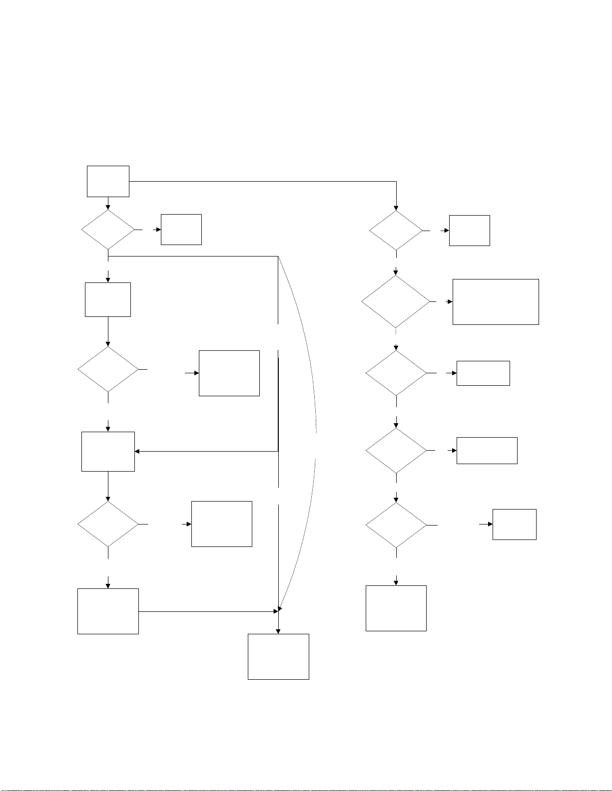
Sequence of Operation
The main power supply provides power to both the motor controls and the coil. The blower interlock relay
is the common link between the two circuits, as shown below. Once in normal operation, the coil
modulating stage will energize first and then subsequent power stages as required.
Main Circuit
Main Power
Supply
External
Disconnect
Switch
On
Freeze-Stat
Powered
Discharge
Temperature
Warmer Then
Freeze-Stat Set-Point
Motorized
Damper Actuator
Energized
Damper End
Switch
Off
Colder Then
Freeze-Stat
Set-Point
End Switch
Does Not
Make
Nothing
Happens
Blower Shuts Down
After Time Setting
on Freeze-Stat
Passes
Damper Opens,
Nothing Else
Happens
No Freeze-
Stat
Provided
No Damper
Provided
No Freeze-Stat
or
Damper Provided
Coil
Disconnect
Switch
On
Blower Interlock
Energized
Yes
Air flow Switch
Energized
Yes
Thermal Limit
Tripped
No
Outside Air
Temperature
Off No Heat
No Heat - No Power to
No
Blower Interlock Relay -
Follow Flow Chart to Left
No Heat - Not
No
Enough Airflow
Overheat Situation -
Yes
Not Enough Airflow
Warmer Then
Thermostat
Set-Point
No Heat
Requirement
End Switch
Makes
Supply Motor
Contactor is
Energized, Motor
Starts
Cooler Then Thermostat
Set-Point
Coil Step Controller
is Energized -
Heating Begins
Normal Operation
Coil Blower
Interlock Relay is
Energized
14
Page 15
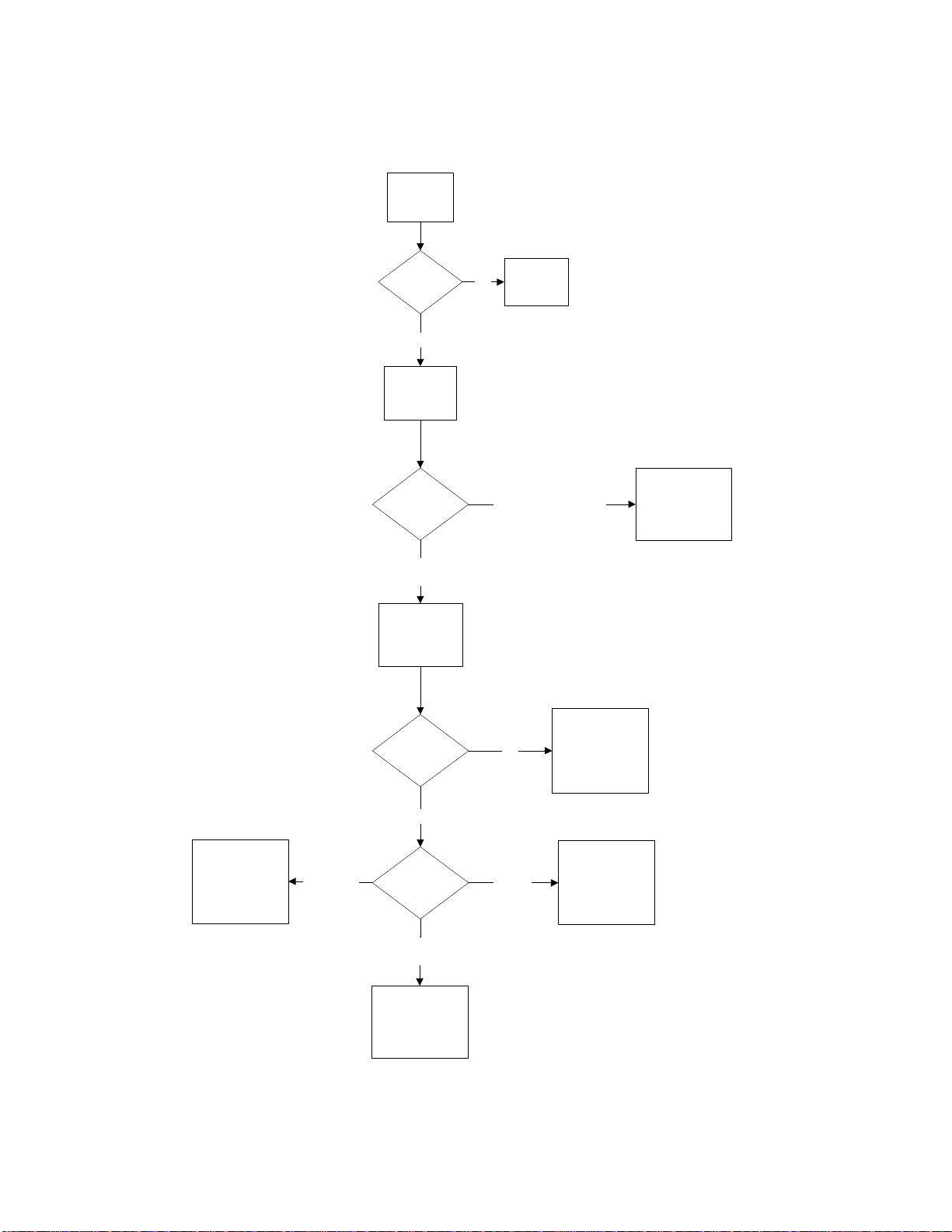
Optional Remote Panel Circuit
Power
Supply From
Heater
"Power" LightOnOff
Panel is
Powered
Blower Switch
"Blower On"
Position
Power is Sent to
Heater to Open
Damper (if
provided) and
Start Blower
"Blower On"
Light
No Power to
Panel
"Blower Off"
Position
(3-Position Panels Only)
Damper is not
Open or Freeze-
Off
Stat has Detected
Low Temperature
Operation
Nothing Happens
No Power is Sent
to Heater
On
Blower Operates
Cooling Circuit is
Energized
"Cool"
Position
(if provided)
Temperature
Control Switch
"Heat"
Position
"Heat On" Light
Turns On
Heat Circuit is
Energized
"Vent"
Position
Blower Operates
Heat Does not
Operate
15
Page 16
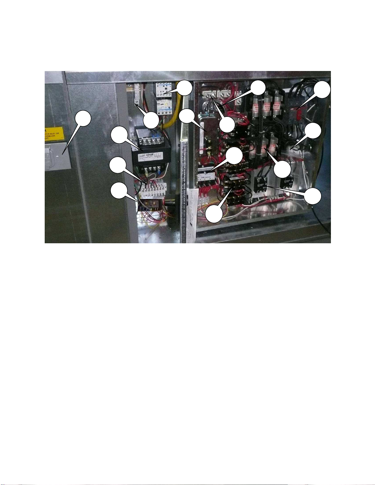
Components
The following image and list outlines the common electric heater components and their functions.
1
2
7
3
5
4
6
9
14
10
8
11
13
12
15
1. Motor Disconnect Switch – Interrupts power to blower motor and controls.
2. Motor Starter – Contactor with overload protection to start and protect motor.
3. Power Transformer – Installed when motor voltage > 120V. Used to provide 120V service to
controls.
4. Freeze-Stat Thermostat (Optional) – De-energizes blower motor if the discharge air
temperature falls below the set point.
5. Terminal Strip – Central location to terminate control wiring. Should be used for troubleshooting.
6. Airflow Switch – A safety device insuring proper air flow during coil operation.
7. Circuit Breaker – Protects electrical components from high current spikes.
8. Automatic Reset Thermal Limit – Safety device that prevents the coil from overheating.
9. Coil Termination – Wire connection to coil element.
10. Coil Contactor – Energizes coil when there is a signal from step controller.
11. Line Fuse – Fuse protecting coil from over amperage.
12. Control Transformer – 120V primary; 24V secondary control transformer.
13. Coil Disconnect Switch – Interrupts power to electric coil.
14. Stage Controller – Controls multiple heating stages in a pre-determined sequence. Works in
conjunction with a proportional thermostat (not shown). A sensor is mounted in blower for
discharge control. The set-point is mounted remotely for either space control or discharge
control.
15. SCR – Modulates power to the electric coil.
16
Page 17
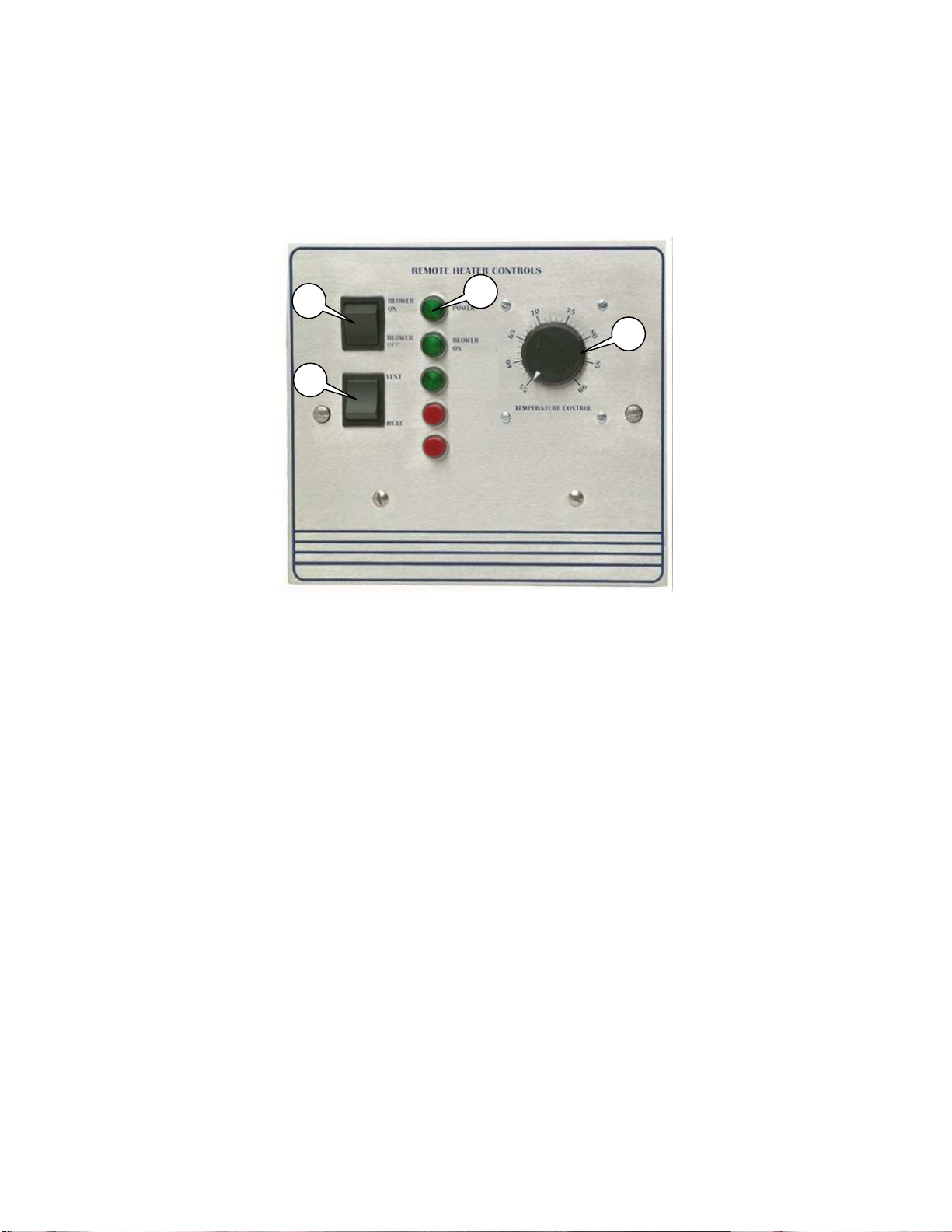
Remote Panel Option
1
2
3
4
LOW
TEMP
CLOGG
ED
HEAT
ON
The Remote Panel is a device used to control the operation of the heater from a remote location. This
unit is available in both a “2 Position” and “3 Position” configuration, and with or without a cooling output.
It also will accommodate both discharge and space heating configurations. It is important to understand
the following Remote Panel controls and uses:
1. Blower On/Blower Off Switch - Used to control blower operation and tempering mode of unit.
The Blower On position sends power to the blower motor and the heater begins to ventilate. The
Blower Off position turns the blower and heating functionality off. This switch is disabled when
the “2 Position” remote panel is ordered and fan power is then controlled by the pre-wire
package.
2. Heat/Vent Switch – This switch is used to control the tempering mode of the unit. The VENT
position will prevent the burner from operating and the heater will deliver untempered air. The
HEAT position will force the heat circuit on and the unit will heat the incoming air. This switch
becomes a Heat/Vent/Cool switch when the cooling interlock is ordered. This option provides a
120V cooling output from the remote panel.
3. Lights- Displays the current status of unit features. The light definitions are as follows:
POWER - Illuminated when there is power to Remote Panel.
BLOWER ON - Illuminated when the blower motor is powered.
HEAT ON - Illuminates after heat circuit is energized.
LOW TEMP - (Optional) Illuminated when the Freeze-stat turns off blower.
CLOGGED FILTER – (Optional) Illuminated when the Intake Filters are Dirty.
4. Temperature Control – Controls the discharge temperature of a standard unit. Can be
configured to control space temperature.
April 2011 Rev. 13
Page 18
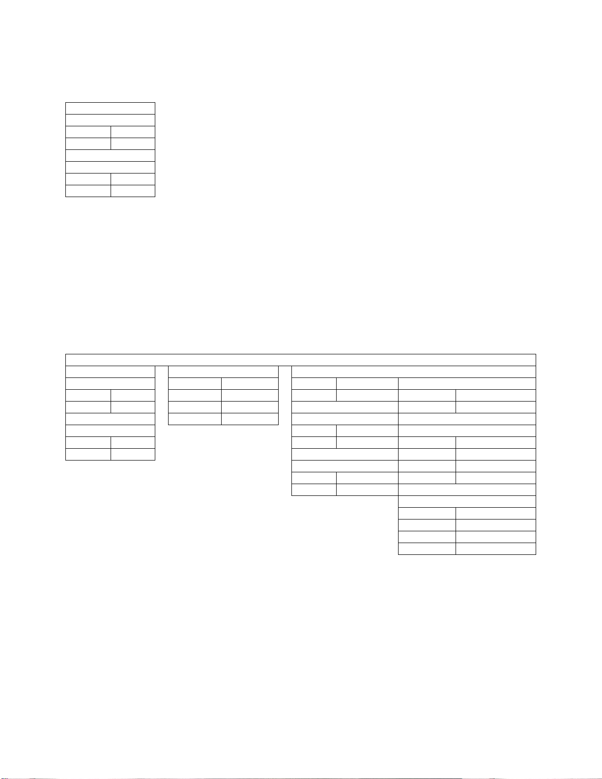
Modulating Coil Thermostat Dip Switch Settings
Thermostat
Step Controller and Thermostat Dip Switch
Setting Chart
Thermostat
Step Controller Input
Step Controller Control
Discharge Control
S1 On
S2 Off
Space Heating
S1 Off
S2 On
To test and verify all coil circuits during startup, perform the following:
• Discharge Control: Disconnect one wire to the discharge air sensor to simulate a call for
maximum amperage.
• Space Control: Set the Thermostat dipswitches to discharge control.
Once maximum amperage is achieved and tested, configure wiring and dipswitches to their original state.
Step Controller Coil Thermostat Dip Switch Settings
Discharge Control S1 Off S1 On 4 Stage Heating
S1 On S2 Off S2 Off S3 On
S2 Off S3 Off S4 On
S4 On 2 Stage Heating
Space Heating S3 On 5 Stage Heating
S1 Off S4 Off S3 Off
S2 On S4 Off
3 Stage Heating S5 On
S3 Off S6 Off
S4 On
8 Stage Heating
S3 On
S4 On
S5 On
S6 Off
18
Page 19
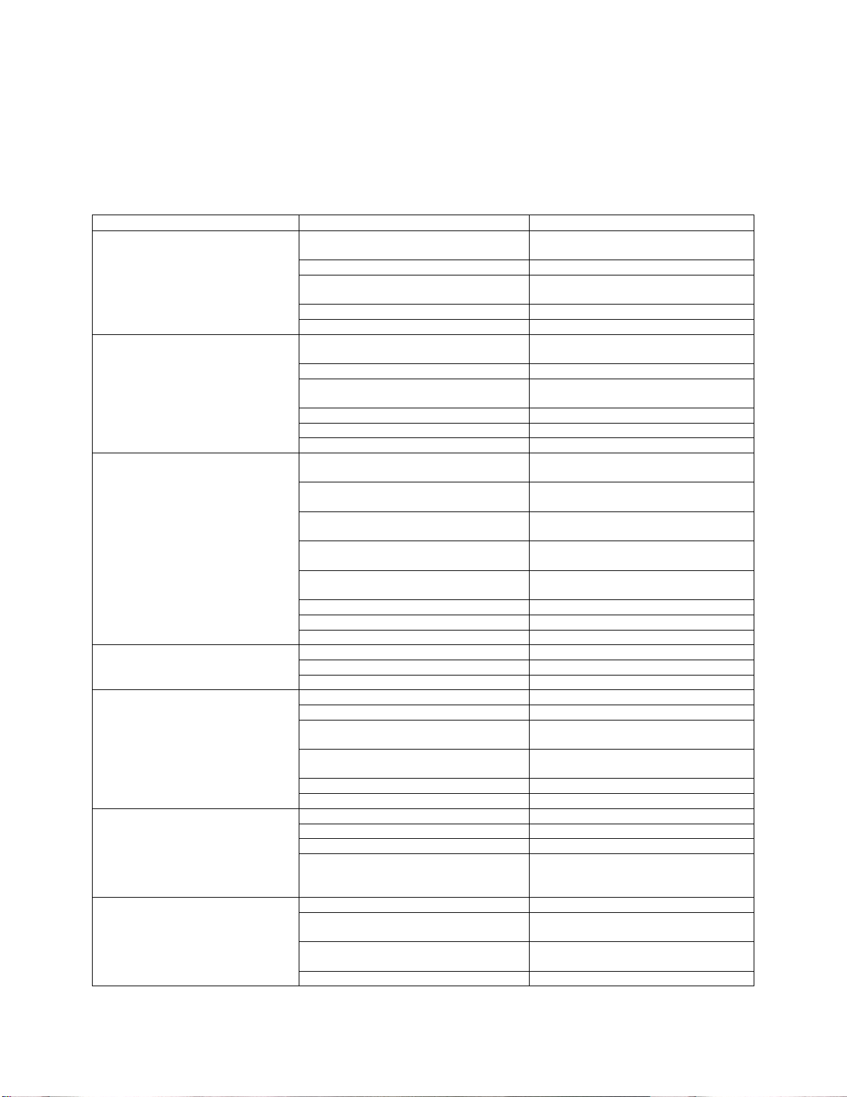
Troubleshooting
The following table lists causes and corrective actions for possible problems with electric heater units.
Review this list prior to consulting manufacturer.
Troubleshooting Chart
Problem
Fan Inoperative Blown fuse or open circuit breaker Replace fuse or reset circuit breaker
Motor Overload Fan rotating in the wrong direction Be sure fan is rotating in the direction
Insufficient Airflow Fan rotating in the wrong direction Be sure fan is rotating in the direction
Excessive Airflow Blower speed to high Reduce fan RPM
Excessive Vibration and Noise Misaligned pulleys Align pulleys
Insufficient Heat Blown fuses Inspect and replace if needed
No Heat Blown fuses Inspect and replace if needed
Potential Cause
Disconnect switch in “Off” position Turn to “On” position
Motor wired incorrectly Check motor wiring to wiring diagram
Broken fan belt Replace belt
Motor starter overloaded Reset starter and check amps
Fan speed is too high Reduce fan RPM
Motor wired incorrectly Check motor wiring to wiring diagram
Overload in starter set too low Set overload to motor FLA value
Motor HP too low Determine if HP is sufficient for job
Duct static pressure lower than design Reduce fan RPM
Poor outlet conditions There should be a straight clear duct
Intake damper not fully open Inspect damper linkage and replace
Duct static pressure higher than
design
Blower speed too low Increase fan RPM. Do not overload
Supply grills or registers closed Open and adjust
Dirty or clogged filters Clean and/or replace
Belt slippage Adjust belt tension
Filters not installed Install filters
Duct static pressure lower than design Reduce fan RPM
Damaged or unbalanced wheel Replace wheel
Fan is operating in the unstable region
of the fan curve
Bearings need lubrication or
replacement
Fan speed is too high Reduce fan RPM
Belts too loose, worn or oily Inspect and replace if needed
Thermostat setting too low Increase thermostat setting
Excessive airflow Reduce fan RPM
Insufficient coil power Check incoming voltage and
Airflow switch not energized Increase fan RPM (Sensing tube
Hi-limit activation Insufficient airflow. Increase fan
Improper coil wiring Inspect coil power wiring
Corrective Action
and check amps
located on fan motor
shown on rotation label
located on fan motor
shown on rotation label
at the outlet
damper motor if needed
Improve ductwork to eliminate or
reduce duct losses
motor
Refer to performance curve for fan
Lubricate or replace
amperage with all coil stages on and
compare to nameplate values
should be curved toward air flow)
RPM.
19
Page 20
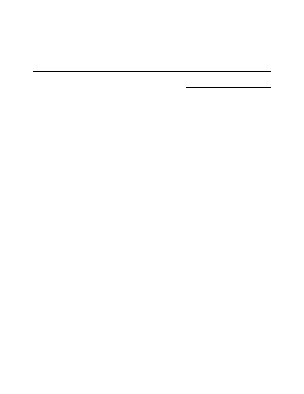
Remote Panel Troubleshooting Chart
Light Indication
No Lights Power not available to Remote Panel Bad voltage to unit
POWER Light Only Proper unit Off Operation No problem
POWER Light and
BLOWER ON Light
CLOGGED FILTER Light On
(Optional)
LOW TEMP Light On
(Optional)
POWER Light and
BLOWER ON Light and
HEAT ON Light
Condition
No power to motor starter Blower On/Blower Off Switch in “Blower
Proper Ventilation Operation No Problem
No Power to Heat Circuit Heat/Vent Switch in “Vent” Position
Filters Clogged Filters Dirty or Need Replacement
Freeze-stat has shut blower down Discharge Temperature Too Cold
Proper Heating Operation No Problem
Possible Cause
Main disconnect in “OFF” Position
Circuit breaker tripped
Bad main transformer
Off” Position
Improper damper function
Low Temperature Thermostat Timed
Out (Option)
Heating System is not Functioning
20
Page 21

MAINTENANCE
To guarantee trouble free operation of this heater, the manufacturer suggests following these guidelines.
Most problems associated with fan failures are directly related to poor service and maintenance.
Please record any maintenance or service performed on this fan in the documentation section located at
the end of this manual.
WARNING: ELECTRIC HEATERS HAVE TWO POWER INPUTS. DO NOT ATTEMPT
MAINTENANCE ON THE HEATER UNTIL BOTH THE MOTOR AND COIL
ELECTRICAL SUPPLY HAVE BEEN COMPLETELY DISCONNECTED.
General Maintenance
1. Fan inlet and approaches to ventilator should be kept clean and free from any obstruction.
2. Motors are normally permanently lubricated. Check bearings periodically. If they have grease
fittings lubricate each season. Use caution when lubricating bearings, wipe the fittings clean, the
unit should be rotated by hand while lubricating. Caution: Use care when touching the exterior
of an operating motor. Motors normally run hot and may be hot enough to be painful or
cause injury.
3. All fasteners should be checked for tightness each time maintenance checks are preformed prior
to restarting unit.
4. Blowers require very little attention when moving clean air. Occasionally oil and dust may
accumulate causing imbalance. If the fan is installed in a corrosive or dirty atmosphere,
periodically inspect and clean the wheel, inlet and other moving parts to ensure smooth and safe
operation.
5. The electric coil should be kept free of dirt and foreign matter that may cause uneven air patterns.
Hot spots on the coil can shorten the life of the coil.
2 weeks after startup
1. Belt tension should be checked after the first 2 weeks of fan operation. Belts tend to stretch and
settle into pulleys after an initial start-up sequence. Do not tension belts by changing the
setting of the motor pulley, this will change the fan speed and may damage the motor. To retension belts, turn the power to the fan motor OFF. Loosen the fasteners that hold the blower
scroll plate to the blower. Rotate the motor to the left or right to adjust the belt tension. Belt
tension should be adjusted to allow 1/64” of deflection per inch of belt span. Exercise extreme
care when adjusting V-belts as not to misalign pulleys. Any misalignment will cause a sharp
reduction in belt life and produce squeaky noises. Over-tightening will cause excessive belt and
bearing wear as well as noise. Too little tension will cause slippage at startup and uneven wear.
Whenever belts are removed or installed, never force belts over pulleys without loosening
motor first to relieve belt tension. When replacing belts, use the same type as supplied by the
manufacturer. On units shipped with double groove pulleys, matched belts should always be
used.
2. All fasteners should be checked for tightness each time maintenance checks are preformed prior
to restarting unit.
3. Inspect the electric coil. All elements should be in the proper location and clean. If an element is
missing or broken, replace coil immediately.
21
Page 22
Every 3 months
Intake
16” x 20”
20”
x 25”
1. Belt tension should be checked quarterly. See instructions in the previous maintenance section.
Over-tightening will cause excessive bearing wear and noise. Too little tension will cause
slippage at startup and uneven wear.
2. Filters need to be cleaned and/or replaced quarterly, and more often in severe conditions.
Washable filters can be washed in warm soapy water. When re-installing filters, be sure to install
with the airflow in the correct direction as indicated on the filter.
3. Inspect the electric coil. All elements should be in the proper location and clean. If an element is
missing or broken, replace coil immediately.
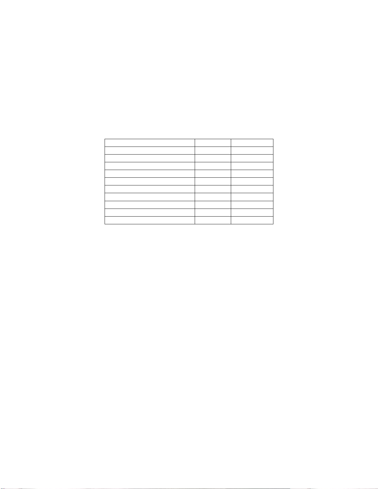
Filter Quantity Chart
Size 1 Sloped 3
Size 2 Sloped 3
Size 3 Sloped 6
Size 4 Sloped 10
Size 5 Sloped 8
Size 1 V-Bank 3
Size 2 V-Bank 8
Size 3 V-Bank 8
Size 4 V-Bank 15
Size 5 V-Bank 12
Yearly
1. Inspect bearings for wear and deterioration. Replace if necessary.
2. Inspect belt wear and replace torn or worn belts.
3. Inspect bolts and set screws for tightness. Tighten as necessary.
4. Inspect for cleanliness. Clean exterior surfaces only. Remove dust and grease from the motor
housing to ensure proper motor cooling. Remove dirt and grease from the wheel and housing to
prevent imbalance and damage.
5. Inspect the electric coil. All elements should be in the proper location and clean. If an element is
missing or broken, replace coil immediately.
22
Page 23
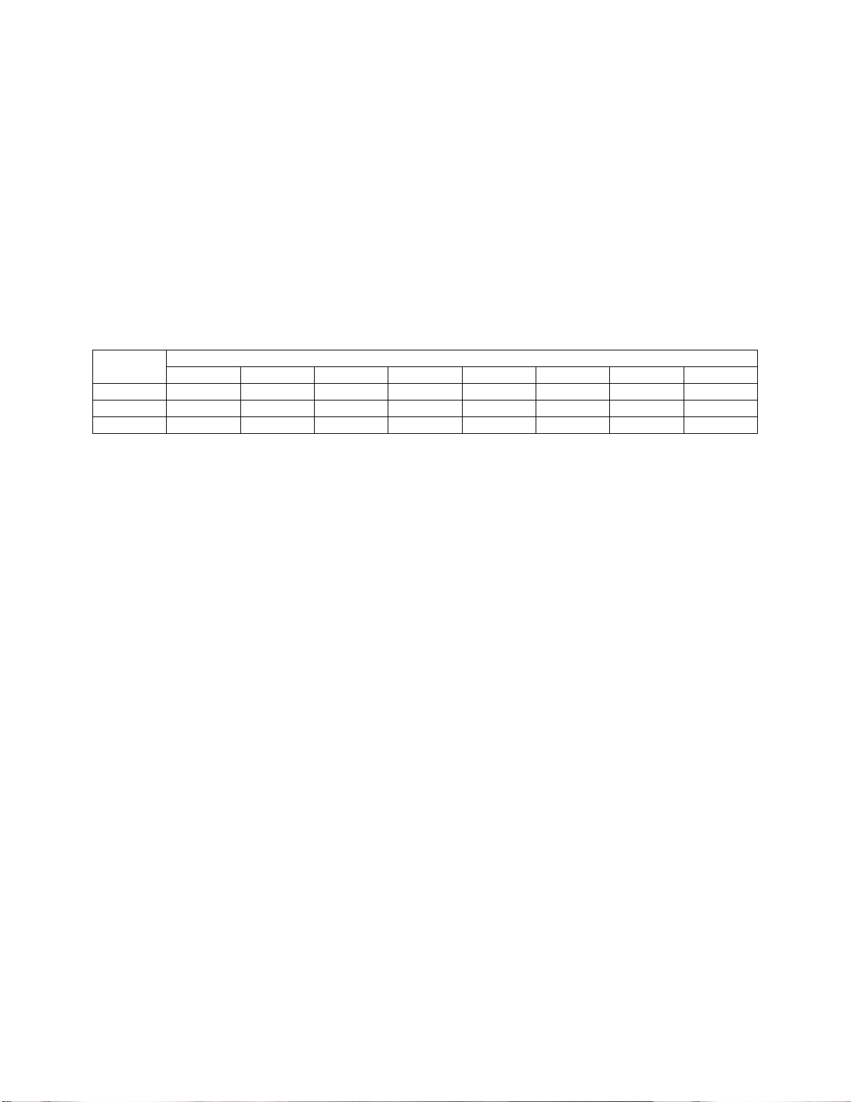
Common Electric Heater Calculations
Conversion:
1 KW = 3413
Load Requirement:
KW = (CFM x Temperature Rise) / 3160
Line Current (3 Phase):
Amperage = (KW x 1000) / (Volts x 1.73)
Line Current (1 Phase):
Amperage = (KW x 1000) / Volts
Applied vs. Rated KW Factors
Rated
Voltage
208 .92 1.00 1.12 1.22 1.33
460 .91 1.00 1.09
480 .84 .92 1.00
Applied Voltage
200 208 220 230 240 440 460 480
23
Page 24
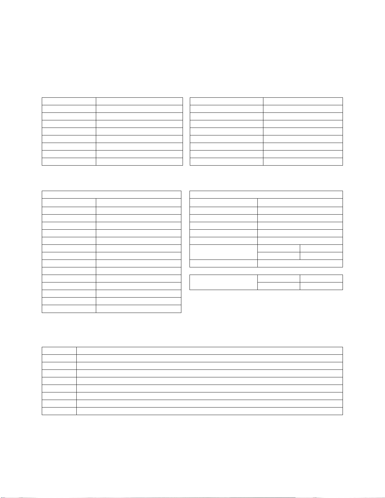
Start-Up and Maintenance Documentation
START-UP AND MEASUREMENTS SHOULD BE PERFORMED AFTER THE SYSTEM HAS BEEN
AIR BALANCED AND WITH THE HEAT ON. (Warranty will be void without completion of this form)
Job Information
Job Name Service Company
Address Address
City City
State State
Zip Zip
Phone Number Phone Number
Fax Number Fax Number
Contact Contact
Purchase Date Start-Up Date
Heater Information
Refer to the start-up procedure in this manual to complete this section.
Name Plate and Unit Information
Model Number
Serial Number
Coil Voltage
Coil Hertz
Coil Phase
Coil FLA
# of Steps
Motor Volts
Motor Hertz
Motor Phase
Motor FLA
Motor HP
Blower Pulley
Motor Pulley
Belt Number
**
If measured amps exceed the FLA rating on the nameplate, fan RPM must be reduced to decrease the
measured amps below the nameplate FLA rating.
Field Measured Information
Coil Voltage
Coil Amperage
Motor Voltage
Motor Amperage**
RPM
Thermostat Set-Point
Temperature Control Discharge
Space
# of Operating Steps
Airflow Direction Correct
Incorrect
Maintenance Record
Date Service Performed
Factory Service Department
Phone: 1-866-784-6900
Fax: 1-919-554-9374
24
 Loading...