

Page 1

Pollution Control Unit Specification
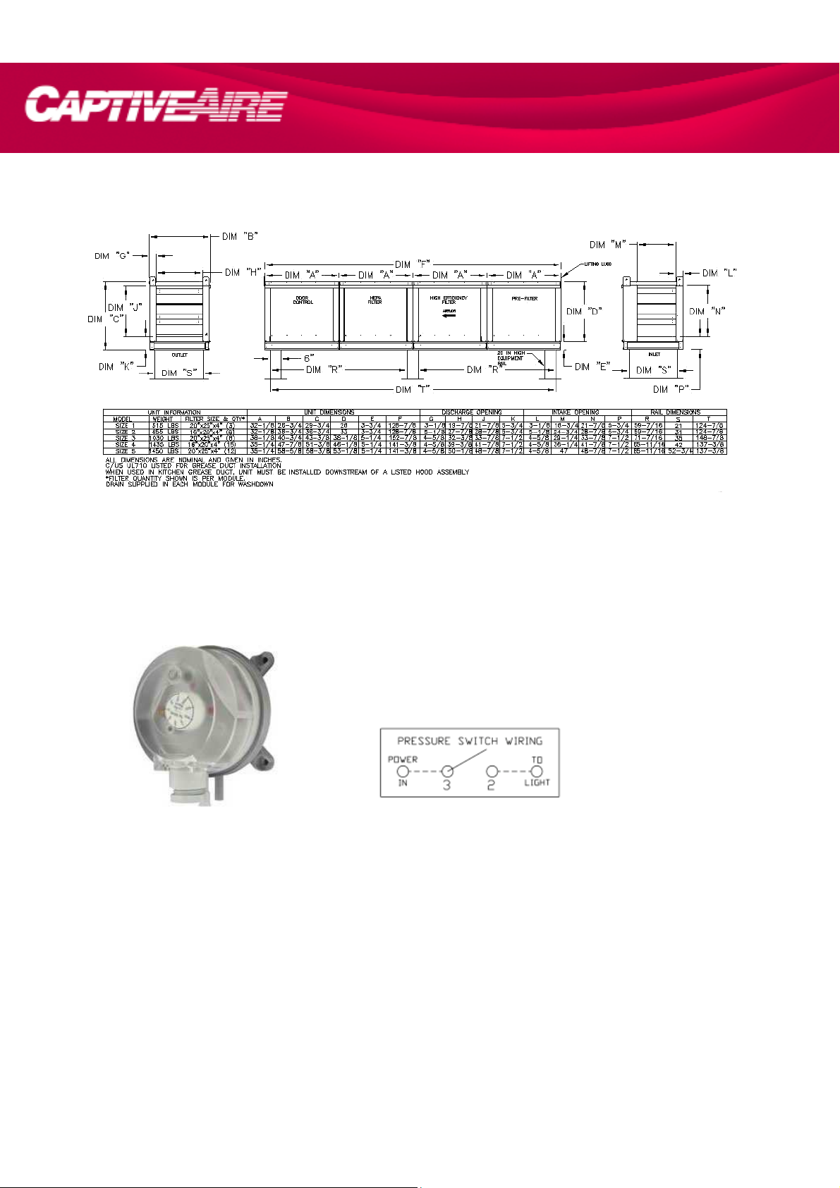
Construction
PCU Series shall be factory assembled pollution control unit capable of significantly reducing smoke, grease and odor
from the exhaust air stream.
Housing: The PCU housing is to be constructed of 430 SS of polish 2B or better. All metal in contact with the air-stream is
to be constructed of 430 SS. 1500°F Ceramic based gasket must be in place for all internal seams exposed to airflow.
High temperature weatherproofing gasket must be used on all exterior seams. A 1 ½” NPT drain is to be installed in the
base of each module of the unit to aid in cleaning. An airflow switch must be installed in the final compartment of the PCU
to enable an indicating light.
Base: The base shall be constructed of galvanized steel for improved rigidity. Base shall be structurally reinforced to
accommodate the filter assembly.
Pre-Filter Section: The pre filter section shall include 4 inch deep steel washable permanent filters. Filter frames and
media shall be constructed of steel. Filters shall be arranged in a v-bank configuration to increase filter area and reduce
static pressure. All filters shall be removable without the use of tools through side access doors with lift and turn latches.
Filters are to be cleanable with a water hose and soapy water. The filters shall have a minimum average arrestance of
75% in accordance with ASHRAE 52.1-1992.
High Efficiency Filter Section: The phase two filters shall consist of 4 inch deep rigid cell extended surface filters. Filter cell
sides shall be constructed of high strength, high impact polystyrene plastic for durability. Beverage board filter sides shall
not be permitted. Filters shall be arranged in a v-bank configuration to increase filter area and reduce static pressure. All
filters shall be removable without the use of tools through side access doors with lift and turn latches. Filters are to be
rated MERV 14 minimum in accordance with ASHRAE standard 52.2 and have a minimum average arrestance of 98% in
accordance with ASHRAE 52.1-1992. High Efficiency module must be installed downstream of pre-filter module.
Odor Control Media Section (Optional): The unit shall be provided with a 50% potassium permanganate 50% carbon
blend (100% permanganate) (100% carbon) (Caustic impregnated) media. The odor removal cartridges shall be encased
in steel frames. The odor removal media shall be arranged in a v-bank configuration to increase filter area and reduce
static pressure. All media shall be removable without the use of tools through side access doors with lift and turn latches.
Odor control module must be installed downstream of High Efficiency module or HEPA module.
Fire Damper (Optional): A fire damper shall be installed into the intake of the Odor Control Media section to prevent the
spread of flames through the Pollution Control Unit. The damper must be capable of 1 ½ hour fire rating and must be set
to activate at 285° F. The use of this damper will require the deactivation of the fan during a fire condition.
Certifications
The PCU Series has been certified by ITS. This certification mark indicates that the product has been tested to and has
met the minimum requirements of a widely recognized (consensus) U.S. and Canadian products safety standard, that the
manufacturing site has been audited, and that the applicant has agreed to a program of periodic factory follow-up
inspections to verify continued performance. Models PCU are ETL Listed under file number 3130718COL-001 and comply
with UL710 Standards and ULC710 Standards.
Page 2
Typical Installation
Typical Installation of Air Pressure Switch
Switches are preset from plant to 0.15” w.c. above the internal static pressure of the PCU with clean filters. The Air
pressure switch is located in the downstream filter module. Route wiring from hood control panel to PCU using ½” conduit
through quick seal located near lower right area of filter module containing switch. Use existing conduit in module to route
wires from exterior of module to switch. Install wiring according to label above switch. Be sure all conduit fittings are tight.
Once filters become clogged, switch closes illuminating light in kitchen. User should then clean or replace filters as
required.
Page 3

Pressure Drop Curve
PCU Size 1 Shown
Page 4

Centrifugal PCU Exhaust Fan Specification
Model KB fan shall be a backward incline, roof mounted or indoor, belt drive, up-blast centrifugal exhaust ventilator. Steel
centrifugal roof exhausters are engineered to discharge grease laden vapors, fumes and other contaminants.
Construction
Housing: The fan housing shall be constructed of stainless steel. The internal structural support and external mounting
material shall be 14 GA G90 galvanized steel minimum.
Base: The base shall be constructed of galvanized steel for improved rigidity. Bolt patterns shall be provided in the base
to allow connection to a pollution control unit.
Wheel: The fan wheel shall be centrifugal backward inclined and non-overloading. Wheels shall be balanced in two planes
and done in accordance with AMCA standard 204-96, Balance Quality and Vibration Levels for Fans. The wheel blades
shall be aerodynamically designed to minimize turbulence, increase efficiency and reduce noise. The wheel blades shall
be welded to the wheel inlet cone. In the event that balancing weights are required they shall be riveted to the blades or
wheel. The wheel inlet shall overlap the fan inlet for maximum performance and efficiency. The wheel shall be firmly
attached to the motor shaft with two setscrews.
Motor & Motor Compartment: Motors shall be heavy-duty ball bearing type, mounted on an adjustable base and furnished
at the specified voltage, phase and enclosure. Motor mounting plate shall be constructed of heavy gauge steel and
isolated from the fan structure with vibration isolators. The motor shall be Totally Enclosed and Fan Cooled and have high
temp class F insulation. Motors shall be washdown duty. The motor compartment shall be of a two-piece construction
quick release clips to provide quick and easy access to the motor compartment.
Shaft & Bearings: Shafts shall be precision ground and polished. Heavy duty, pre-lubricated bearings shall be selected for
a minimum (L50) life in excess of 200,000 hours of operation at maximum cataloged operating speed. They shall be
designed for and individually tested specifically for use in air handling applications.
Belts & Drives: Belts shall be oil and heat resistant, non-static type. Drives shall be cast type, precision machined and
keyed and secured attached to the fan and motor shafts. Drives shall be sized for a minimum of 150% of the installed
motor horsepower. Fan operating speed shall be factory set using adjustable pitch motor pulleys.
Safety Disconnect Switch: A safety disconnect switch shall be standard on all units. Switches shall be installed in a
NEMA3R enclosure and mounted to exterior of the fan for easy access.
Certifications
Captive-Aire Systems, Inc. certifies that KB models shown herein are ETL Listed under file numbers 3158877SAT-001
and comply with UL762 Standards and CSA Standard C22.2, No. 113.
Page 5

Typical Installation
Pressure Drop Curve
Model KB10 Shown
 Loading...