

Page 1
Installation & Maintenance Instructions
2-WAY PILOT-OPERATED OR DIRECT - ACTING SOLENOID VALVES
NORMALLY CLOSED OPERATION Ċ 3/4I, 1I, OR 1 1/2I NPT
FUEL GAS SERVICE
SERIES
K3A6
K3A7
Form No.V8501
Service Notice
Except for coil replacement, the Series K3A6 and K3A7 are
not repairable. When any performance problems are
detected during routine inspection, replace valve
immediately.
DESCRIPTION
Series K3A6 and K3A7 valves are 2-way normally closed
solenoid valves designed for fuel gas service. Series K3A6 is
a pilot-operated solenoid valve, while Series K3A7 is
direct-acting. Valve bodies are made of rugged aluminum
with trim and internal parts made of steel and stainless steel.
These valves are provided with a general purpose junction box
solenoid enclosure.
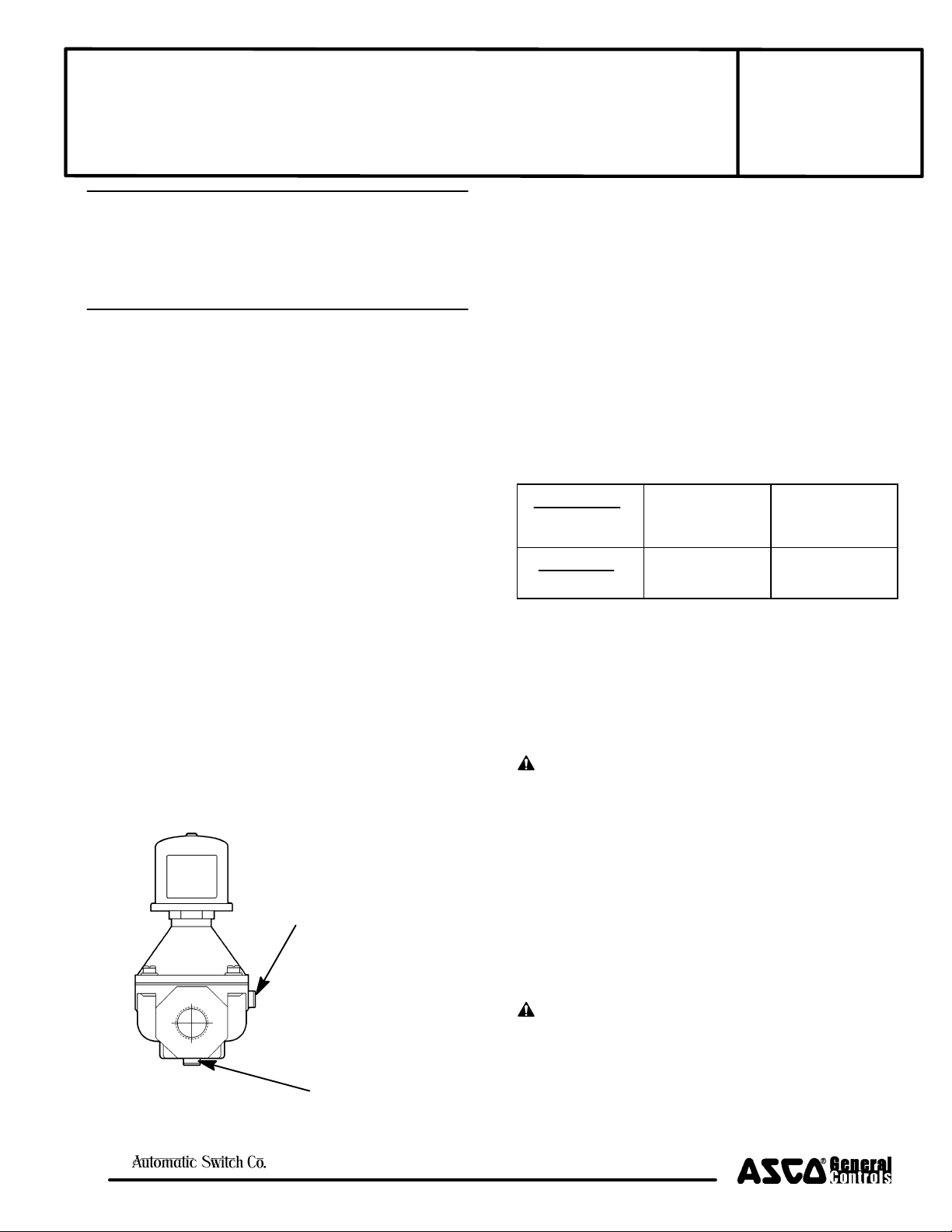
Provisions for Pressure and Seat Leakage Testing
Series K3A6 and K3A7 valves are provided with two 1/8I NPT
tapped and plugged holes (pressure taps). The upstream
tapped and plugged hole is on the side of the valve body;
downstream on the bottom of the valve body. One upstream
for pressure testing; one downstream for seat leakage testing.
Leakage testing frequency shall be at least annually in
accordance with NFPA-86 or original equipment
manufacturer recommendations. For instructions, refer to
section on Testing for Internal (Seat) Leakage and Figure 3.
Partial view of valve body showing location
of tapped and plugged holes for pressure
and seat leakage testing
Pipe plugs are 1/8I NPT
(use 3/16I Hex Key Wrench)
Tapped and pluged hole
(pressure tap)
on side of valve body
for upstream pressure
testing
OPERATION
Normally Closed: Valve is closed when solenoid is
de-energized; open when energized.
Note: No minimum operating pressure differential required.
INSTALLATION
Check nameplate for correct catalog number, pressure,
voltage, frequency, and service. Never apply incompatible
fluids or exceed pressure rating of the valve. Installation and
valve maintenance to be performed by qualified personnel.
Temperature Limitations
Coil Class
Temperature
Rating
F
311_F (155_C)
Nominal
Fluid
Temperature
77_F(25_C)
Ambient
Temperature
Range
-40_F (-40_C) to
175_F (80_C)
Positioning
Valve must be mounted with solenoid vertical and upright or
in a horizontal position only. Valves equipped with rainproof
housings (W in the 3rd character position of the valve catalog
number) must be mounted in a vertical and upright position
only.
Piping
CAUTION: Piping must comply with applicable
local and national codes and ordinances, including the
National Fuel Gas Code ANSI Z223.1/NFPA No. 54.
Connect piping to valve according to flow arrow on bottom of
valve body. Apply pipe compound sparingly to male pipe
threads only. If applied to valve threads, the compound may
enter the valve and cause operational difficulty. Avoid pipe
strain by properly supporting and aligning piping. When
tightening the pipe, do not use valve or solenoid as a lever.
Locate wrenches applied to valve body or piping as close as
possible to connection point. Valve should be checked for
external leakage at piping connections after installation, see
Testing for External Leakage section.
Tapped and pluged hole
(pressure tap)
on bottom of valve body
for downstream seat
leakage testing
Figure 1. Provisions for pressure and seat leakage testing.
e
50-60 Hanover Road, Florham Park, New Jersey 07932
MCMXCVII All Rights Reserved.
CAUTION: To avoid damage to the valve body, DO
NOT OVERTIGHTEN PIPE CONNECTIONS. If Teflon*
tape, paste, spray, or similar lubricant is used, use extra
care when tightening due to reduced friction.
*DuPont's Registered Trademark
Page 1 of 4
Printed in U.S.A.
Valves & Actuators
Page 2

CAUTION: To protect the solenoid valve, install a
strainer or filter, suitable for the service involved, in the
inlet side as close to the valve as possible. Clean
periodically depending on service conditions. See
ASCO Series 8600, 8601 and 8602 for strainers.
Wiring
Wiring must comply with local codes and the National
Electrical Code. To facilitate wiring, the solenoid enclosure
may be rotated 360_ by loosening the screw on the top of the
enclosure. Rotate enclosure to desired position, then torque
screw to 10 - 13 in-lbs [1,1 - 1,5 Nm]. The junction box
housing has two 7/8I diameter knockouts to accommodate
1/2I conduit. Drive out appropriate knockout with junction
box completely assembled (with cover) for support. Remove
J" box cover, by spreading cover and disengaging nibs (lift up
and pull down simultaneously). The coil jacket is provided
with a grounding screw (green) and a tab for the grounding
connection. Within the junction box solenoid enclosure use
field wire that is rated 90_ C or greater for connections.
Replace"J" box cover before operating.
Testing for External Leakage
WARNING: To prevent the possibility of
severe personal injury or property damage,
extinguish all open flames and avoid any type of
sparking or ignition.
1. Block gas flow on downstream side of valve.
2. Apply pressure to valve within nameplate rating and
energize solenoid.
3. Apply a soapy solution or a commercially available leak
detecting solution to the pipe connections and check for
bubbles. If the valve has been tested for seat leakage,
apply the solution around the pipe plugs.
4. If leakage exists, depressurize valve and turn off
electrical power supply. Tighten connections as required
and retest following the above steps.
Solenoid Temperature
Series K3A6 and K3A7 valves are supplied with coils designed
for continuous duty service. When the solenoid is energized
for a long period, the solenoid enclosure becomes hot and can
be touched with the hand for an instant. This is a safe operating
temperature. Any excessive heating will be indicated by the
smoke and odor of burning coil insulation.
Preventive Maintenance
S Prepare and follow a routine inspection schedule based on
the media, environment, and frequency of use. This should
include periodic internal and external leakage checks.
S Keep the medium flowing through the valve as free from
dirt and foreign material as possible.
S While in service, the valve should be operated at least once
a month to ensure proper opening and closing.
NOTE: For performance problems, refer to Troubleshooting
Chart on page 4 of 4.
Coil Replacement (Refer to Figure 2)
NOTE: It is not necessary to remove the valve from the pipeline for
Coil Replacement.
CAUTION: Exercise care to prevent damage to the
plunger tube. Do not grasp plunger tube with wrench or
pliers.
1. Remove cover and disconnect supply wires to coil,
grounding wire, and rigid conduit from coil jacket.
2. Remove screw and lockwasher, then carefully lift coil
jacket assembly off plunger tube.
3. Remove the spring, coil, coil frames and washers from
the coil jacket.
4. Reassemble in reverse order of disassembly, using a new
replacement coil.
5. Place inner washers, then coil frames onto coil as
originally configured. Coil voltage markings on coil must
face toward valve body.
6. Place the spring inside the coil jacket.
7. Insert coil lead wires through hole in coil jacket. Pull
wires all the way through, and seat coil in jacket.
8. Place bottom washer inside coil jacket.
9. Place coil/jacket assembly on plunger tube.
10. Install lockwasher, and screw onto coil jacket. Torque
screw to 10-13 in-lbs [1,1-1,5 Nm].
11. Make electrical connections to solenoid, see Wiring
section.
12. Replace J" box cover on coil jacket.
CAUTION: Solenoid must be fully reassembled as
the coil jacket and internal parts are part of and
complete the magnetic circuit.
MAINTENANCE
WARNING: To prevent the possibility of
severe personal injury or property damage, turn
off electrical power, depressurize valve,
extinguish all open flames and avoid any type of
sparking or ignition. Vent hazardous or
combustible fluid to a safe area before inspection
or removing the valve from service.
Page 2 of 4
Valves & Actuators
Form No.V8501
50-60 Hanover Road, Florham Park, New Jersey 07932
Page 3

Figure 2. Exploded view, typical K3A valve.
4. Shut off the upstream manual gas cock and de-energize
valve. Remove the plug from the leak test tap or
downstream pressure tap in the valve body. Connect leak
test equipment with the test petcock in the closed position
(Figure 3).
5. Open the upstream manual gas cock. Program the
control system to energize the valve to the full open
position, then immediately de-energize it to seat the
valve operationally.
6. Immerse the 1/4I leak test tube vertically into a jar of
water to a depth of about 1/2I. Slowly open the test
petcock. Bubbles may appear in the water as the pressure
equalizes.
7. After the rate of bubbles coming through the water
stabilizes, count the number of bubbles appearing in a 10
second period. The allowable leakage in 10 seconds for
an orifice diameter of 1 inch (25.4 mm) or less is 6
bubbles (3 cc/min). For valves with an orifice diameter
over 1 inch (25.4 mm) the allowable leakage rate is 6
bubbles (3 cc/min.) per inch (25.4 mm) of orifice
diameter. If leakage exceeds this rate, replace valve.
NOTE: The leakage rate above recognizes that some wear
and contamination from use can result in a slight amount of
leakage. The allowable leakage rate is well within the leakage
limits as recognized by applicable approval agencies.
8. Close the upstream manual gas cock and the test petcock.
Then remove the test equipment. Apply a small amount
of Loctite Corporation's PSTr Pipe Sealant 567 (or
equivalent) to the pipe plug threads. Reinstall the pipe
plug and tighten securely.
9. Turn on the gas supply at the upstream manual gas cock
and energize the valve.
10. Open the upstream manual gas cock. Program the
control system to energize and maintain the valve in the
open (energized) position. Check all valve and piping
connections for external leaks with rich soap and water
solution or a commercially available leak detecting
solution.
11. De-energize the valve. Open the downstream manual
gas cock.
12. Restore the system to normal operation.
Testing for Internal (Seat) Leakage (Refer to Figure 3)
CAUTION: Be sure valve can be tested without
affecting other equipment.
1. Shut off both the upstream and downstream manual gas
cocks. The downstream manual gas cock should remain
closed throughout the entire test procedure.
2. Program the control system to operate the valve through
five cycles. Listen carefully for the solenoid coil to click
indicating proper operation.
3. Open the upstream manual gas cock. Program the
control system to energize and maintain the valve in the
open (energized) position. Check all valve and piping
connections for external leaks with rich soap and water
solution or a commercially available leak detecting
solution.
50-60 Hanover Road, Florham Park, New Jersey 07932
Figure 3. Testing for internal seat leakage.
Page 3 of 4Form No.V8501
Valves & Actuators
Page 4

ORDERING INFORMATION
FOR COIL REPLACEMENT
When ordering coils, specify valve catalog number, voltage
and coil number, if possible.
Troubleshooting Chart
Trouble Possible Cause Remedy
Valve operation is sluggish
Valve fails to open
Solenoid coil short, or wrong voltage.
Damaged plunger assembly.
Dirt or other foreign matter restricting
operation of valve.
Timer, limit controls or other devices not
energizing circuit.
Damaged plunger assembly preventing
plunger operation.
Solenoid coil short, burned-out or
wrong voltage.
Dirt, pipe compound or other foreign
matter restricting operation of valve.
Check coil voltage. Replace solenoid
coil.
Replace valve.
Replace valve and install strainer
upstream of valve.
Check circuit for limit control operation,
blown fuse, short circuit and loose
wiring.
Replace valve.
Replace with solenoid coil of correct
voltage
Replace valve and install strainer
upstream valve.
Valve fails to close
Valve chatters"
Valves & Actuators
Damaged plunger assembly preventing
plunger operation.
Dirt, pipe compound or other foreign
matter restricting operation of valve.
Limit controls improperly installed to
grounded side.
Valve supply voltage is improper
(too low)
Dirt or chips between top of plunger
assembly and plunger tube.
Page 4 of 4
Replace valve.
Replace valve and install strainer
upstream of valve.
Wire controls in hot side of circuit.
Apply correct voltage to valve.
Replace valve and install strainer
upstream of valve.
Form No.V8501
50-60 Hanover Road, Florham Park, New Jersey 07932
 Loading...