

Page 1
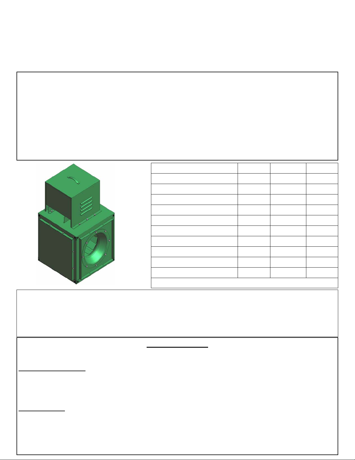
BELT DRIVE SQUARE INLINE BLOWERS
1
OPERATION INSTRUCTIONS AND PARTS MANUAL
General Safety
Rotating parts, (pulleys, shafts and belts) on fans, should not be exposed. Where these components
are not protected by ductwork, cabinets or covers, appropriate guards should be employed to restrict
exposure to rotating parts. Access doors should never be opened with the fan running to avoid the
sucking in foreign objects into the system. On initial start up, a careful inspection should be carried
out to ensure no foreign material is present which could become airborne in the system.
Read installation and operation instructions carefully before attempting to install, operate or service.
Failure to comply with instructions could result in personal injury and/or property damage. Retain
instructions for future reference.
General
Size Max.H.P. Shaft Dia. Weight
10 1 ¾ in. 62
12 1-1/2 ¾ in. 73
13 1-1/2 ¾ in. 85
15 2 ¾ in. 95
16 3 ¾ in. 123
18 3 1 in. 140
20 3 1 in. 165
22 5 1 in. 211
24 7-1/2 1-3/16 in. 241
27 7-1/2 1-3/16 in. 280
All shafts are keywayed
Inspect unit for damage, report any shipping damage to carrier. Check all fasteners, retighten as required. Rotate the blower wheel by hand to ensure free rotation If rubbing
occurs, loosen the set screw(s), re-position the wheel to establish clearance, re-tighten
set screws.
Installation (Fig. 1)
The (4) angle brackets provided allow for base or suspension mounting
Suspension Mounting
For suspension mounting, install the (4) angle iron mounting brackets in the 4 upper corners (front &
rear or both sides ) using the hardware provided, secure the unit to 4 customer provided suspension
rods.
Base Mounting
For base mounting, install the (4) angle iron mounting brackets in the 4 lower corners (front & rear or
both sides) and secure to customer supplied base.
Vibration Isolation (not included)
Recommended (spring or rubber) for both suspension or base mount
Page 2
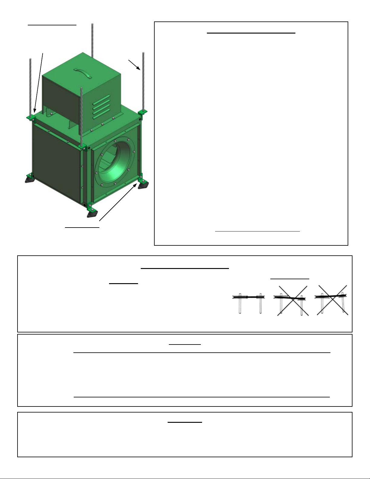
Suspension Mount
2
Install 4 supplied angle iron
mounting brackets on
upper cabinet front & rear
or sides (illustrated)
Customer
supplied
suspension
rods (4)
Fig. 1
Base Mount
Install 4 supplied angle iron mounting on
Cabinet bottom front & rear (illustrated)
or both sides.
Motor, Pulleys & Belts
1. Select the appropriate drive set (motor, sheaves
& belts) from the drive table (page 3) to obtain the
blower RPM that will deliver the design
performance (CFM & SP).
2. Remove the access panel from the drive compartment to expose the blower shaft. Mount the
blower sheave on the shaft end and tighten the
setscrew securely.
3. Remove the motor compartment cover to expose
the motor mounting platform. Secure the motor to
the platform, mount the adjustable motor pulley to
the shaft end, align with the blower pulley using a
straight edge ( see Fig. 2) and tighten the setscrew to secure the pulley to the motor shaft.
4. Install the belt(s) and raise the end of the pivoting
motor platform to tension the belt and secure the
platform in place with the positioning screws located on both sides of the platform.
DO NOT OVER TENSION
Belt Tension & Alignment
Warning
EXCESSIVE BELT TENSION IS THE MOST FREQUENT CAUSE
OF BEARING WEAR AND RESULTING NOISE.
PROPER BELT TENSION IS CRITICAL
FOR QUIET EFFICIENT OPERATION
Belt Alignment
Fig. 2
Ideal belt tension is the lowest value under which belt slip will
not occur at peak load conditions
Correct Wrong Wrong
Electrical
Warning:
Before connecting the motor to the electrical supply, check the electrical characteristics and wiring instructions as indicated
on the motor nameplate or inside the conduit box cover to ensure proper voltage and phase. Complete electrical connections as indicated.
Ensure power supply is disconnected & locked out prior to making electrical connections
Warning:
A ground wire must be connected from the motor housing to a suitable electrical ground.
Operation
1. After electrical connections are completed, energize the unit momentarily and ensure proper wheel rotation.
2. Apply full power.
3. With the air system in full operation, all ducts attached and both access doors in place, measure the motor current
and ensure that it is less than the rated full load motor amperage as indicated on the motor nameplate.
Page 3

- - - B83 -
3
B78 - - B82 -
MOTOR FRAME
56/143T 182T 56/143T 182T 56/143T 182T 56/143T 182T 56/143T 182T 213T 56/143T 182T 213T
- - - - -
B76 - - B80 -
B75 - - - -
56/143T
56/143T
56/143T
56/143T
10 12 13 15 16 18 20 22 24 27
Pulley Pulley Range 48 /145T 48 /145T 48 /145T 48 /145T 48 /145T /184T /145T /184T /145T /184T /145T /184T /145T /184T /215T /145T /184T /215T
1VL34 AL104 335-512 - - - - - - - - - - - - - 4L67 - 4L75 - - - - - - -
AL94 373-570 - - - - - - 4L58 - - - - - - 4L66 - 4L74 - - - - - - -
DRIVES
Motor Blower RPM
Based on 1725 RPM Motor
AL64 567-865 - - 4L47 - 4L50 - 4L53 - 4L53 - - 4L58 - 4L61 - - - - - - - - - AL51 686-1047 4L41 4L42 4L45 - 4L48 - 4L51 - 4L52 - - 4L56 - 4L59 - - - - - - - - -
AK41 886-1352 4L40 4L40 4L44 - 4L47 - 4L50 4L50 4L50 4L51 - - - - - - - - - - - - - AK30 1171-1787 4L38 4L39 4L42 4L43 4L45 4L46 - - - - - - - - - - - - - - - - -
MAX. AL74 483-738 - - - - 4L52 - 4L55 - 4L55 - - 4L59 - 4L63 - 4L71 - - - - - - -
3/4 HP AL84 421-643 - - - - - - 4L57 - - - - 4L61 - 4L65 - 4L73 - - - - - - -
BK100H 364-556 - - - - - - 4L59 - - - - - - 4L67 - 4L75 - 4L80 - - 4L84 - -
BK90H 410-625 - - - - - - 4L57 - - - - 4L61 - 4L65 - 4L73 - 4L79 - - - - -
1VL34 BK110H 328-500 - - - - - - - - - - - - - - - - - - - - 4L86 - -
BK80H 468-715 - - - - 4L52 - 4L55 - 4L55 - - 4L60 - 4L63 - 4L71 - - - - - - -
BK60H 656-1001 4L42 4L43 4L46 - 4L49 - 4L52 - 4L52 - - B55 - B58 - - - - - - - - - BK50H 819-1251 4L40 4L41 4L44 - 4L47 - 4L50 - 4L50 - - B53 - B56 - - - - - - - - - BK40H 1024-1563 4L39 4L40 4L43 - 4L46 - 4L49 - - - - B52 - B55 - - - - - - - - -
BK70H 546-834 - - 4L48 - 4L50 - 4L53 - 4L54 - - 4L58 - 4L61 - 4L70 - - - - - - -
AL94 550-747 - - - - - - 4L60 - - - - - - 4L68 - 4L76 - - - - - - -
1VL44 AL104 483-656 - - - - - - - - - - - - - - - - - - - - - - -
AL64 836-1134 4L44 4L45 4L48 - 4L51 - 4L54 - 4L55 - - 4L59 - - - - - - - - - - - AL51 1010-1371 4L43 4L44 4L47 - 4L50 - 4L53 4L53 - 4L54 - - - - - - - - - - - - -
AK41 1305-1772 4L41 4L42 4L45 4L46 4L48 4L49 - - - - - - - - - - - - - - - - - AK30 1725-2341 4L40 4L40 - 4L44 - - - - - - - - - - - - - - - - - - -
MAX. AL74 712-967 - - 4L50 - 4L53 - 4L56 - 4L56 - - 4L61 - 4L64 - - - - - - - - -
3/4 HP AL84 621-843 - - - - 4L55 - 4L58 - - - - 4L62 - 4L66 - - - - - - - - -
BK100H 537-728 - - - - - - 4L60 - - - - - - 4L68 - B74 - B80 - - B84 - -
BK90H 604-819 - - - - 4L55 - 4L58 - - - - 4L63 - 4L66 - B73 - B78 - - B82 - -
1VL44 BK110H 483-656 - - - - - - - - - - - - - - - - - B82 - - B85 - -
BK80H 690-936 4L47 4L47 4L51 - 4L53 - 4L56 - 4L57 - - 4L61 - 4L64 - B71 - B76 - - B80 - -
BK60H 966-1311 4L43 4L44 4L47 - 4L50 - 4L53 - - B52 - B56 - B59 - B68 - - - - - - - BK50H 1208-1639 4L41 4L42 4L45 - 4L48 B48 - B51 - B51 - B54 - - - - - - - - - - - BK40H 1509-2048 4L40 4L41 - 4L45 - B46 - B49 - B50 - - - - - - - - - - - - -
BK70H 805-1093 4L45 4L46 4L49 - 4L52 - 4L55 - 4L55 - - B58 - B61 - B69 - - - - - - -
BK90H 637-842 - - - - - - - - - - - - - - - - -
BK80H 723-956 - - - - - - - - - - - - - - - - -
BK70H 836-1105 - - - - - - - - - - - - - - - - B71
BK60H 990-1310 - - - - - - - - - - - - - - B61 - B70
BK50H 1215-1607 - - - - - - - - - - - - B56 - - - -
BK40H 1485-1965 - - - - - - - - - - B52 - - - - - - - - - - - -
BK70H 1524-1811 - 4L49 - - - - - - - - - - - - - - - - - - - - -
BK60H 1829-2174 - 4L48 - B50 - B53 - - - - - - - - - - - - - - - - -
BK50H 2286-2717 - B45 - B49 - - - - - - - - - - - - - - - - - - -
1VP44 BK100H 569-752 - - - - - - - - - - - - - - - - - - - - - B85 -
1VP71 BK80H 1306-1553 - 4L51 - - - - - - - - - - - - - - - - - - - - -
2B74 1142-1375 - - - - - - - - - - - - - - - - - - - B82 - - -
BK40H 2588-3163 - B44 - - - - - - - - - - - - - - - - - - - - -
2VP62 2B86 983-1183 - - - - - - - - - - - - - - - - - - - - - - B87
Note: 4L Belts, AL and AK pulleys are rated to 3/4 HP maximum.
Page 4

MAINTENANCE
4
Ensure power supply is disconnected & locked out prior to making performing maintenance
1. Inspect and tighten all bearing and wheel set screws after the first 50 to 100 hours of operation
and periodically thereafter.
2. Follow motor manufacturer's instructions for motor lubrication. Remove any excess lubrication.
3. Drives: A - Check belt tension and alignment, replace cracked or worn belts. If it is
necessary to replace one belt on a multiple belt drive, replace all the belts with a
matched set.
B - Under normal conditions, no re-lubrication is the rule. The bearing lubricant cavity is
1/3-1/2 filled as shipped from the factory. Never lubricate new bearings.
4. Clean the blower wheel periodically. Material build up on the blades can cause wheel imbala nce
which may result in wheel or bearing failure.
1
2
7
5
6
3
4
Parts List
1 Motor cover
2 Side access panel
3 Motor mounting
platform
4 Drive compartment
access cover
5 Bearings
6 Shaft
7 Wheel
8 Inlet cone
2
8
Warranty
Guaranteed for a period of one year against manufacturing defects
in material and workmanship when operating under normal conditions.
Liability is limited to the replacement of defective parts.
Labour and transportation costs are not included.
SE-40-1
June 2005
 Loading...