


SX50 User Commands
2005.2.2
Communication Specifications
Communication Flow
Error List
Command List
Command System Chart
Power Management Mode
Key
Spaces of 0 or more characters, Tab (09h), other separators
Spaces of 1 or more characters, Tab (09h), other separators
Separators between parameters ,|
[ ]
Characters in [ ] can be omitted
|
Equivalent to OR

Contents
1. Overview
2. Communication Specifications
3. Communication Flow
4. Command System
5. Control Mode
6. Key/Emulation function
7. Power Management Mode
8. Command List
9. Command Descriptions
REMOTE
LOCAL
POWER
INPUT
AUTOPC
DOTS
TRACK
HPOS VPOS
HPIX VPIX
SEL
ASPECT
IMAGE
BRI
CONT
SHARP
GAMMA
DGAMMA
PROG
WB
WBRGB
SAT
HUE
ACADJUST
6AXR~Y
LAMP
RESET
VKS
AVOL
MUTE
BVOL
IMAGEFLIP
PMM
PJON
NOSIG
NOSHOW
LOGOPOS
LANG
TERMINAL
KEYLOCK
RCCH
RC
MAIN
GET
RANGE
10. Error List
11. Miscellaneous
Appendix 1 Reset Items
Item
1. Overvie
w
These specifications describe the methods of controlling the SX50 projector from the PC over an RS-232C connection.
Virtually all operations possible with the remote control can be controlled from the PC.
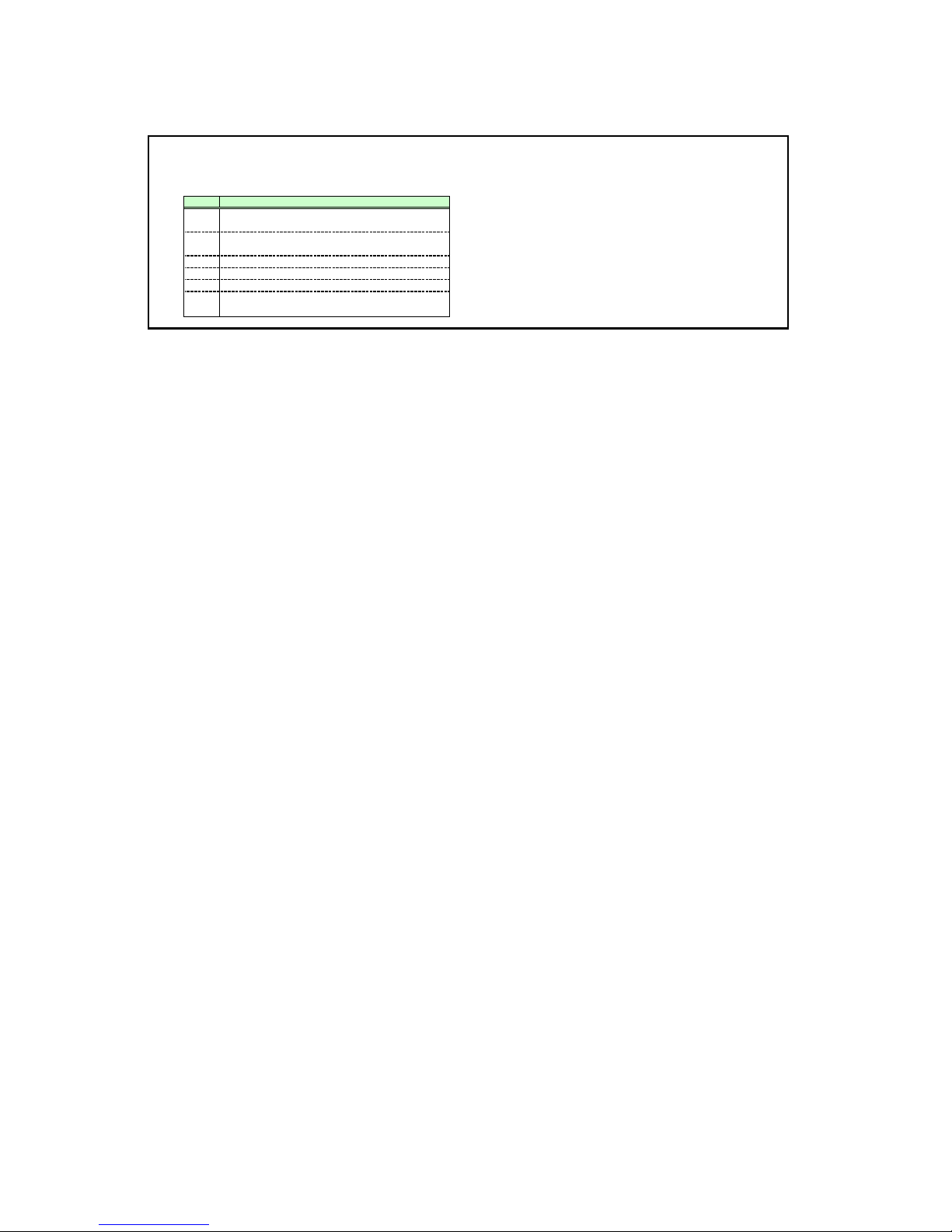
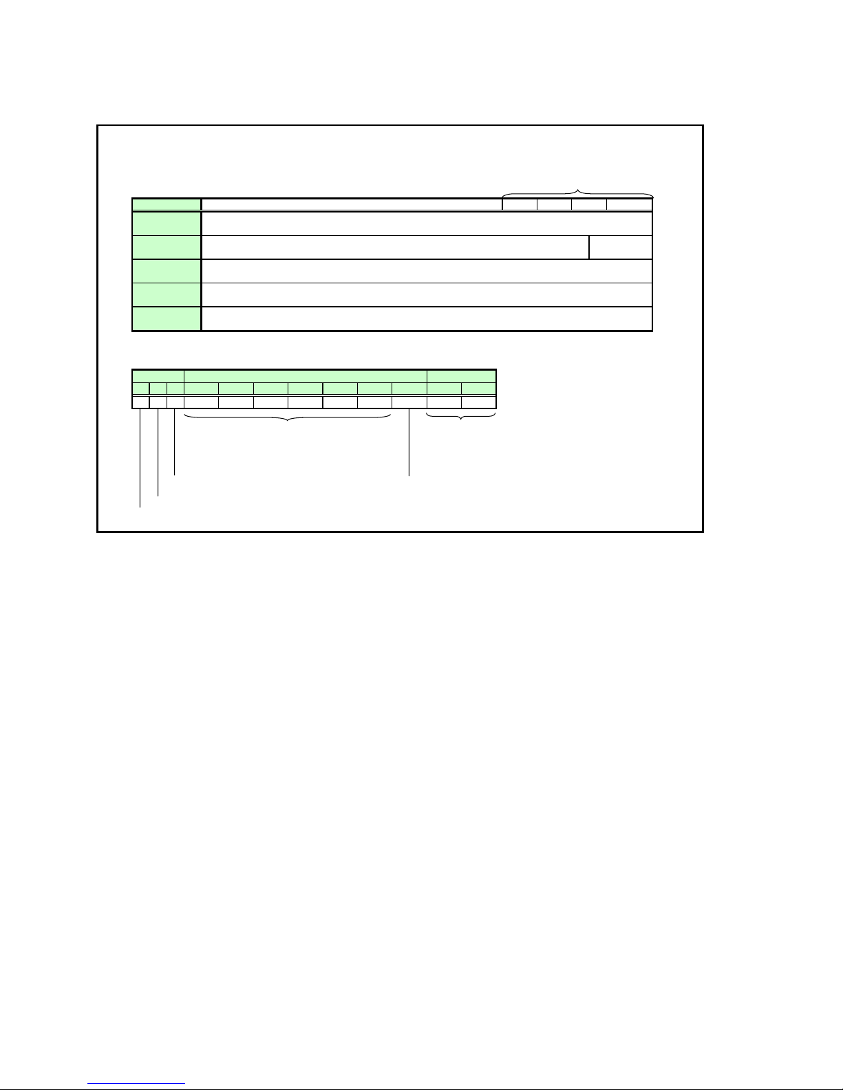
The following symbols are used in these specifications.
Symbol Description
Space with 0 or more characters (20h), Tab (09h), or other
△
separator
Space with 1 or more characters (20h), Tab (09h), or other
□
separator
Separator between parameters ,|□
▽
[ ]
The data in [ ] can be omitted.
|
Same as OR
The definition name is on the left side of this mark, and the
:=
definition description is on the right side.
2. Communication Specifications
Communication
system
Maximum transmission length
Item
Communication system
Transmission speed
Character length
Stop bit
Parity
Transmission format
Delimiters
Transmission codes
Communication procedure
Flow control
Error control
Break signal
Time out
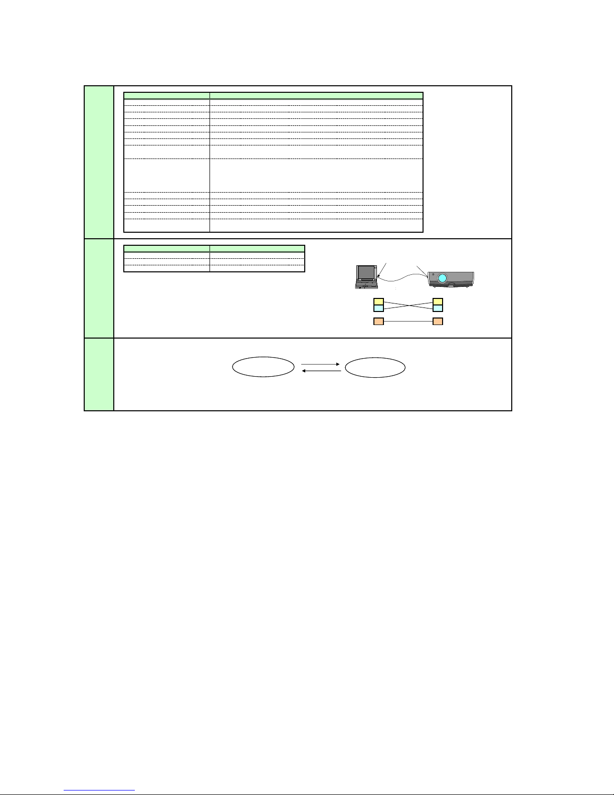
Connection
Specifications
Control
The SX50 has two control modes: LOCAL and REMOTE.
Mode
Most user commands are used in REMOTE mode.
The two modes are set by the REMOTE and LOCAL commands.
Item
Connection system PC: “1:1” connection in SX50
Connection signal line
Connection cable
RS-232-C, Start-stop synchronization, Semi-duplex communication
19.2 Kbps
8 bits/character
2 bits
None
Variable-length record with terminal as delimiter
Maximum of 256 characters (bytes) including delimiters
Delimiters are one of CR, LF, CR+LF, Null (0) (Delimiters are identified automatically.)
Response delimiters are identical to command delimiters.
ASCII code (General-purpose characters: 20h to 7Fh), Tab (09h)
(Codes other than those above and delimiters are considered “other separator codes”.)
Uppercase and lowercase of alphabetic characters are considered the same character.
Double-byte characters and single-byte characters are not distinguished. All are
considered single-byte characters.
No procedure
None
None
Not supported
Tc Character interval: 10 ms
Tr Command/response interval: 10 s
Specifications
3-line connection of SD, RD, and SG
Dedicated cable
Local
• SX50 normal mode
• The available user commands are limited.
REMOTE, LOCAL, RC, MAIN, GET_MODE
only are available
Specifications
REMOTE
LOCAL
PC-SX5 connection status
PC-SX5 接続形態
Send data SD SD Send data
Receive data RD RD Receive data
Signal ground SG SG Signal ground
• Except for RC and MAIN, all user commands are
available in this mode.
• Except for POWER, all remote control and
front panel buttons are disabled.
PC
Remote
PORT
COM
Dedicated cable
専用ケーブル
SERVICE
PORT
Canon
SX50

Commands
Request transmissions sent from PC to SX50
△
Transmission
format
<Command character strings> △<Delimiters>
<Command character strings>
Type
Null
Control
Setting
Reference
Reference
Command character string
Character strings consisting of 0 or more
<Delimiters>
Type Description
Null command
Character string
Control command
Character string
Setting command
Character string
Reference command
Character string
Range request
alphanumeric characters
One of CR (0Dh), LF (0Ah), CR+LF (0Dh+0Ah), Null (00h)
Commands with a command character string length of 0. No command processing is performed.
<Null command character string>:= <Character string with length 0>
Projector control command. The format of the <command control string> is shown below.
If an Ok is not received, the control results may also be returned in some cases.
<Control command character string>:= <Control name> [ <Parameter value>]
Command that sets values for each parameter. The format of the <command character string> is shown below.
<Setting command character strings>:= <Parameter name>△=△<Parameter value>
For the definition of <Parameter value>, refer here.
Command that requests the current setting value of each parameter. The format is shown below.
<Reference command character string>:=? △<Parameter name> | GET <Parameter name>
Command requesting the available setting range for the setting vales of each parameter. The format is shown below.
<Range request command character string>:= RANGE <Parameter name>
Response
■
OK
□
BUSY
■
WARN
■
ERR
□
GET
□
RANGE
■
OK
■
BUSY
■
WARN
■
ERR
□
GET
□
RANGE
■
OK
■
BUSY
■
WARN
■
ERR
□
GET
□
RANGE
□
OK
■
BUSY
■
WARN
■
ERR
■
GET
□
RANGE
□
OK
■
BUSY
■
WARN
■
ERR
□
GET
■
RANGE

Response Transmissions sent from SX50 to PC in response to commands from PC
>
n
>
mission forma
<Response character string> <Delimiter
<Response character string>
Character strings consisting of one or more ASCII characters
The first two characters are always <one lowercase letter>:
The first character indicates the response type.
Response
type
i State response i:OK i:BUSY etc.
w Warning w:USER_COMMAND..
e Error e:000B INVALID..
g Reference command response g:AVOL=10
r
<Delimiters> Delimiters for commands sent from PC
Meaning
Range request command
response
Example
r:VKS=N, -50, 50
Type
BUSY
WARN
ERR
GET
RANGE
Type Description
OK
OK response
After processing of each command is completed, a response is sent indicating that the next command can be received.
<OK response character string>:=i:OK
BUSY response
This response is sent when a command cannot be received during processing.
<BUSY response character string>:=i:BUSY
Example:
> IMAGE=2
< i:BUSY
WARN response This response is sent when warning information is issued. Note that this command cannot be executed.
<Warning response character string>:= w:<Warning description>
> IMAGE=2
Example:
< w:USER_COMMAND_VERSION_IS_UPDATED
ERR response An error message is output.
<Error response character string>:= e:<Error code> <Error message>
※ <Error code> is expressed as a four-digit hexadecimal number.
* Refer to “Error List”!
Example:
> abcdefg
< e:0002 INVALID_COMMAND
GETresponse
Request response for each parameter.
<GET response character string>:=g<Parameter name>=<Value>
Example: > GET LANG or ? LANG
< g:LANG=JPN
RANGE response
This is the settable range response for each parameter.
<Range response character string> := r:<Parameter name>=<Type>, <Setting value range>
※ <For <Setting value range> refer to the RANGE command.
Example:
> RANGE CONT
<
r:CONT=N, -20, 20
Other
Transmissio
recognition
<Parameter
Transmission is recognized when delimiter is received.
Even if a maximum transmission length is received, the entire received transmission will be lost unless a delimiter is received.
The <Parameter value> is defined as shown below.
value
definition
<Parameter value>:=<Value 1>▽<Value 2> ▽.. ▽ <Value n>
<<Value > := <Numerical value > | <Control value > | <Logical value > | <ID> | “<Character string >”
<Numerical value>
<Control value> := On | Off
<ID> := 1 or more ASCII characters
<Character string> := 0 or more ASCII characters (20h to 7Fh)
:= [<Sign>] <Decimal character string ((Min. 1 character to Max. 5
characters)>The range of valid values is -32768 to 32767.

Cable
The connection diagram for the cable connecting the PC and projector is shown below.
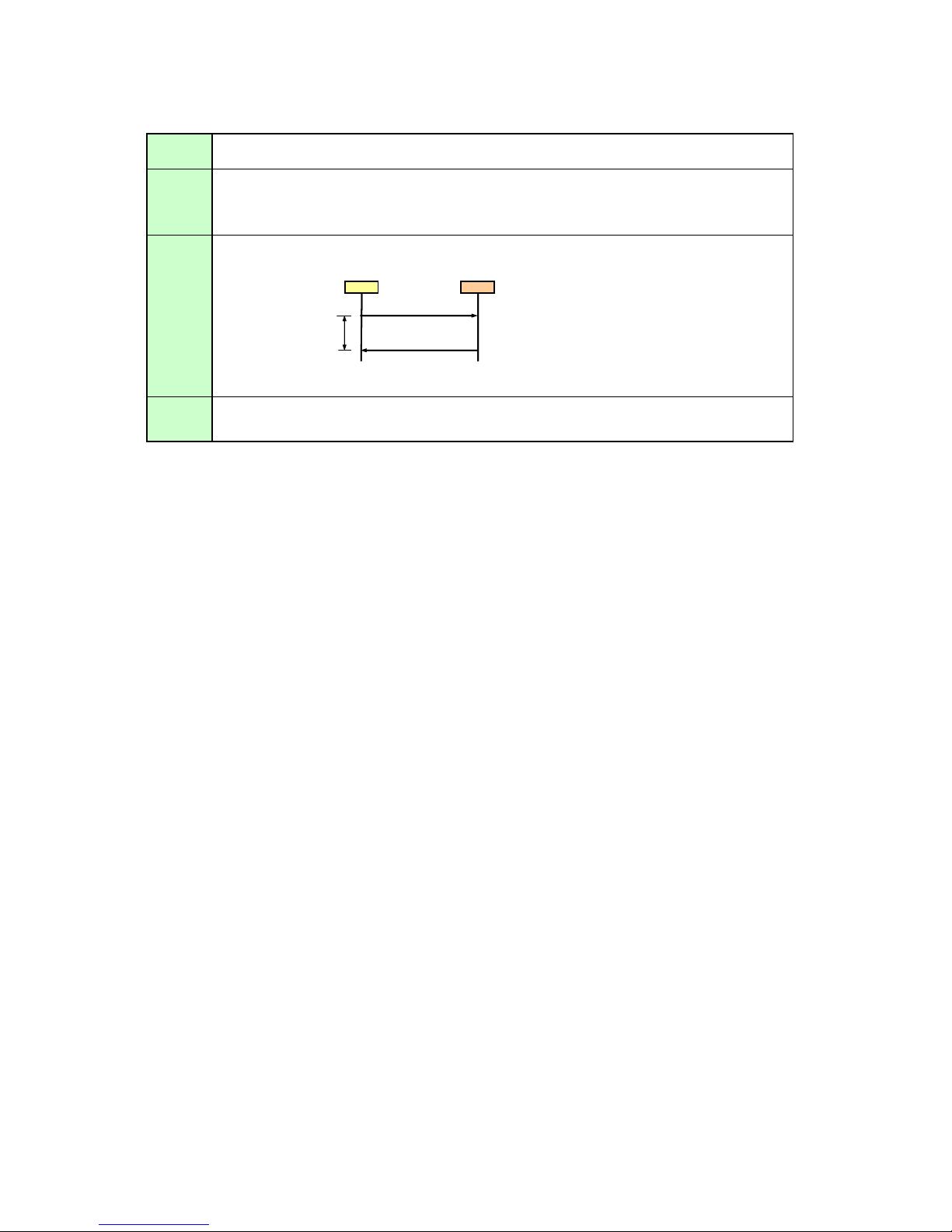
3.Communication Flow
A
Transmission
sent
Transmission
received
Command/ One response is always returned for each command sent from the PC.
Response
Response
reception
timeout
At the sending side (PC), the transmission is sent within character intervals of Tc (character interval timeout).
t the receiving side (SX50), data able to be received within the character interval of Tc is held, and receiving of a delimiter is considered
“transmission received”.
If a received character interval exceeds Tc or a delimiter is not received within 256 characters, all data already received is
lost, and the mode is reset to receive standby again.
(However, note that a response may not be returned when the internal receive buffer overflows due to
reception of a large amount of data.)
PC SX50
Command
Within Tr
Response
*The timeout interval between command and response (Tr) is 10 seconds.
If a response is not received within Tr (timeout interval between command and response) while in response reception standby
after sending a command at the PC, resend the command in the “response reception timeout”.
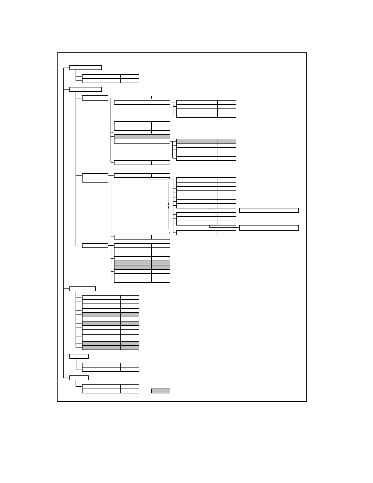
4.Command System
The command system for SX50 “User Commands” is shown below.
Mode change
Switch to Remote mode REMOTE
Switch to Local mode LOCAL
Setting/Control
Display setting Input signal switching INPUT
Input signal setting
Input signal selection SEL
Screen setting ASPECT
Auto PC AUTOPC
Menu display position setting
User screen setting User screen registration
Flip display IMAGEFLIP
Total number of dots adjustment
Tracking adjustment
Horizontal/Vertical position adjustment
Horizontal/Vertical resolution adjustment
DOTS
TRACK
HPOS/VPOS
PIX
* User commands use only automatic selection of input signals.
*Running of Auto PC will change the values set in “Input signal selection”.
User image position LOGOPOS
Input when no signal NOSIG
Screen when nothing shown
Startup screen PJON
NOSHOW
Image adjustment
Image quality select IMAGE
*This is set for each input signal and
image quality.
Image adjustment reset RESET
System setting Terminal setting TERMINAL
Remote control/Key
Power supply
Input switching
Keystone
Auto PC
Spotlight
Volume adjustment
Digital zoom
Image quality select
Audio mute
Display screen setting when
nothing shown
Freeze image
Presentation timer setting
Power management PMM
Electronic sound BVOL
Key lock KEYLOCK
Password registration
Password setting
Remote control setting RCCH
Language setting LANG
Reset RESET RESET SYSTEM
POWER
INPUT
VKS/HKS
AUTOPC *Running of Auto PC will change the values set in “Input signal selection”.
AVOL
IMAGE *Same as “Setting/Control”-“Image Adjustment”-“Image Quality Select”.
MUTE
NOSHOW
Emulate
Remote control emulate RC
Key emulate BTN
Reference
Retrieve each data RET
Setting range request RANGE *
Brightness setting BRI
Contrast setting CONT
Sharpness setting SHARP
Gamma correction GAMMA
Dynamic gamma DGAMMA
Progressive PROG
Screen color correction WB
Color saturation setting SAT
Hue setting HUE
Advanced color correction ACADJUST
RGB adjustment WBRGB
6-axis adjustment (R to Y)
Lamp mode setting LAMP
Indicates functions that are available in the menu but not
available in the user commands.
6AXR TO Y
5. Control Mod
e
a
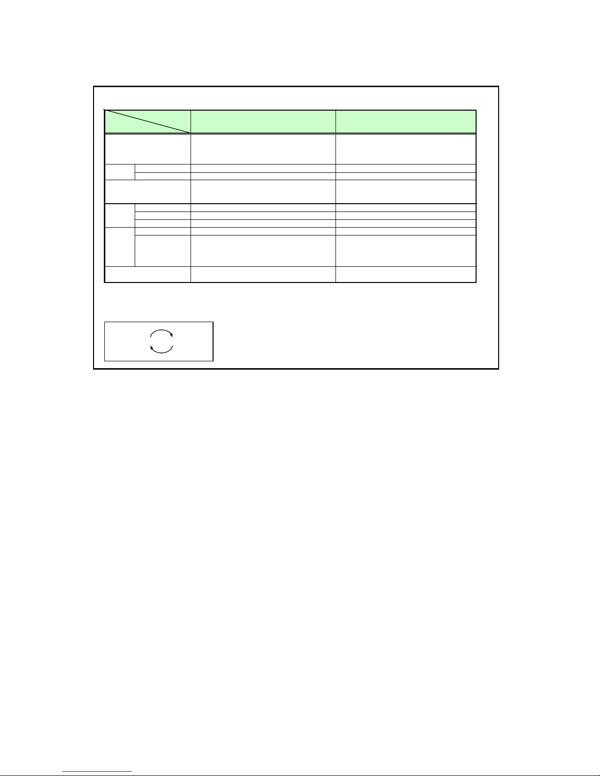
The table below shows the states and limitations of the LOCAL and REMOTE control modes.
Mode
Item
Description
State State indicator Constant remote indic
LED
ALM State indicator State indicator
Transition method
Main unit keys All available Only POWER button is available
Operation
Remote control keys All available Only POWER button is available
buttons
Emulation Available ※1 Not available
Switching 5 minutes elapsed from no signal No switching
Return · Signal input ・REMOTE command
Standby
mode
Special mode
(Service mode)
※1 However, switching to the USB mouse function or Special mode is not allowed.
※2 If the control mode is REMOTE, the following are displayed regardless of whether the power is on or off.
LED indicator pattern during REMOTE mode
Mode where projector control/operation is performed by
the main unit or remote control. Normal mode when
microcomputer is started.
・Microcomputer startup ・REMOTE command
・Manual power on/off
・LOCAL command
· Remote control button pressed
· Main unit button pressed
· Emulation
Executable with remote control or main unit buttons
LOCAL mode REMOTE mode
Mode where projector control/operation is performed by
a PC or other external device.
(The PC or other external device is connected by a
serial cable.)
Not executable in any state
■ ■
※2
6. Key/Emulation function
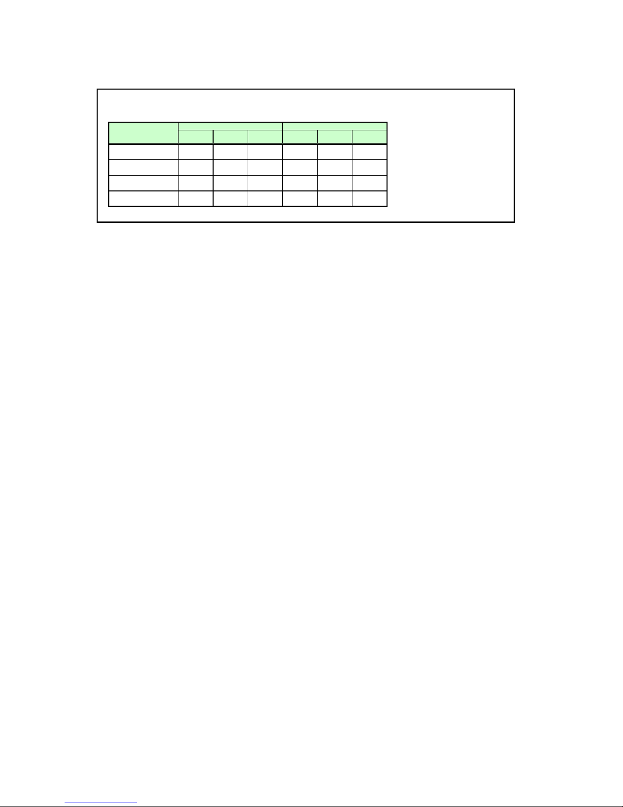
The table below shows how the main unit/remote control keys and Emulation function operate in each control mode.
Key/Emulation
Remote control
Main unit keys
Remote control emulation
Main unit key emulation
LOCAL mode REMOTE mode
Unlock
control lock
○
○
○
○
Remote
× ○
○ ×
○
○ ○
Main unit key
lock
○
Unlock
POWER only ×
POWER only
Remote
control lock
POWER only ×
×
× ×
×
Main unit key
lock
POWER only
×
×
7.Power Management Mod
e
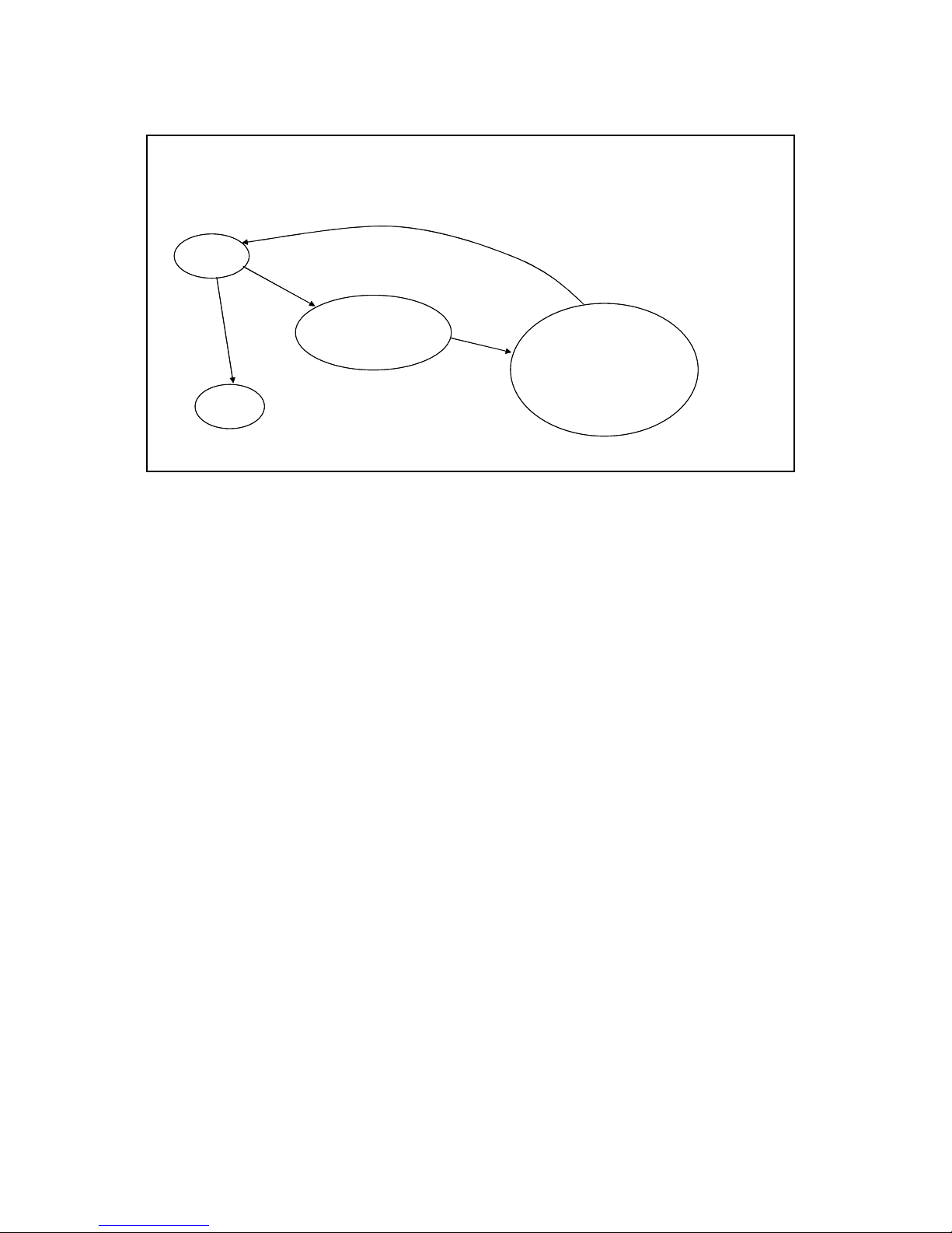
During Remote mode, Power Management is not in standby regardless of the SX50 settings.
If the SX50 is set to REMOTE mode during standby, it changes to the projection state.
Remote mode
Projecting in progress
POWER OFF
Commands Power Management activated
Power Off
Lamp cooling in progress
70 seconds elapsed
Processing only for commands
enabled in Power Management
mode
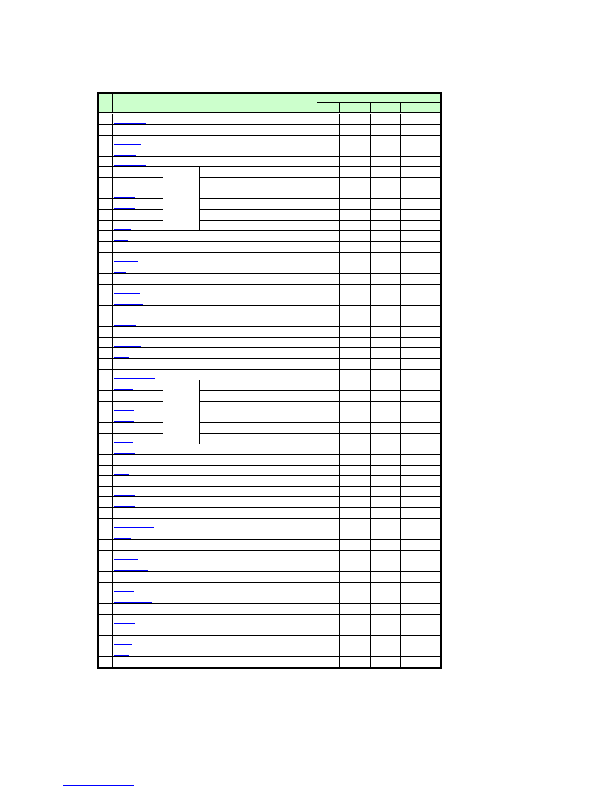
8. Command List
ItemCommand Description Command type
1
REMOTE
2
LOCAL
POWER
3
4
INPUT
5
AUTOPC
6
DOTS
7
TRACK
8
HPOS
9
VPOS
10
HPIX
11
VPIX
12
SEL
13
ASPECT
14
IMAGE
BRI
15
CONT
16
SHARP
17
GAMMA
18
DGAMMA
19
PROG
20
WB
21
WBRGB
22
SAT
23
HUE
24
ACADJUST
25
6AXR
26
6AXG
27
6AXB
28
6AXC
29
6AXM
30
6AXY
31
LAMP
32
RESET
33
VKS
34
HKS
35
AVOL
36
MUTE
37
BVOL
38
IMAGEFLIP
39
PMM
40
PJON
41
NOSIG
42
NOSHOW
43
LOGOPOS
44
LANG
45
TERMINAL
46
KEYLOCK
47
RCCH
48
RC
49
MAIN
50
51
GET
52
RANGE
Switching to Remote mode
Cancel Remote mode
Power supply control
Input terminal select
Auto PC execution
Total number of dots adjustment
Tracking adjustment
Input signal
settings
Input select
Screen settings
Image mode
Brightness setting
Contrast setting
Sharpness setting
Gamma correction
Dynamic gamma
Progressive
Screen color correction
Screen color correction (RGB adjustment)
Color level setting
Color balance setting
Advanced color adjustment
6-axis color
Lamp mode setting
Reset
Trapezoid adjustment (vertical keystone)
Trapezoid adjustment (horizontal keystone)
Volume adjustment
Mute
Beep sound setting
Image flip H/V control
Power management
Display screen at startup setting
Display screen when no signal setting
Display screen when nothing shown setting
User image position setting
Language selection
Terminal setting
Key lock setting
Remote control setting
Remote control emulation
Front panel button operation emulation
Obtains various information
Setting range request
Horizontal position adjustment
Vertical position adjustment
Horizontal resolution adjustment
Vertical resolution adjustment
R setting
G setting
B setting
adjust
C setting
M setting
Y setting
Mode Control Setting Reference
○
○
○
○
○
○
○
○
○
○
○
○
○
○
○
○
○
○
○
○
○
○
○
○
○
○
○
○
○
○
○
○
○
○
○
○
○
○
○
○
○
○
○
○
○
○
○
○
○
○
○
○
y
9. Command Descriptions
Descriptions of each command are provided starting from the next page.
The command descriptions have the format shown below.
※ Command type
Command
※ Alphabetic command name
Function ※ This briefly describes the command function.
Parameters
Response
Description
Supported command states
Power
OFF ON PM
× ○ ×
“○” when power supply state is ON.
“○” when power supply state is OFF.
※ This explains the required parameters for the command.
※ This describes the command response.
※ This includes the command function, conditions, and notes.
Example
※ This provides command usage examples.
※ This defines the environments that support the command (power suppl
D-RGB A-RGB1 A-RGB2 Comp Video S-Video None Remote Local
×××○ ○○× ○
The command is enabled in states marked by “ ○”. The command is
“○” when the power supply state is enabled while power
management is in standby.
Input
Mode Control Setting Reference
state, input signal state, control mode).
Mode
×
enabled in control
modes marked by
“○”.
Input signal is required when “×”.
Parameter
types

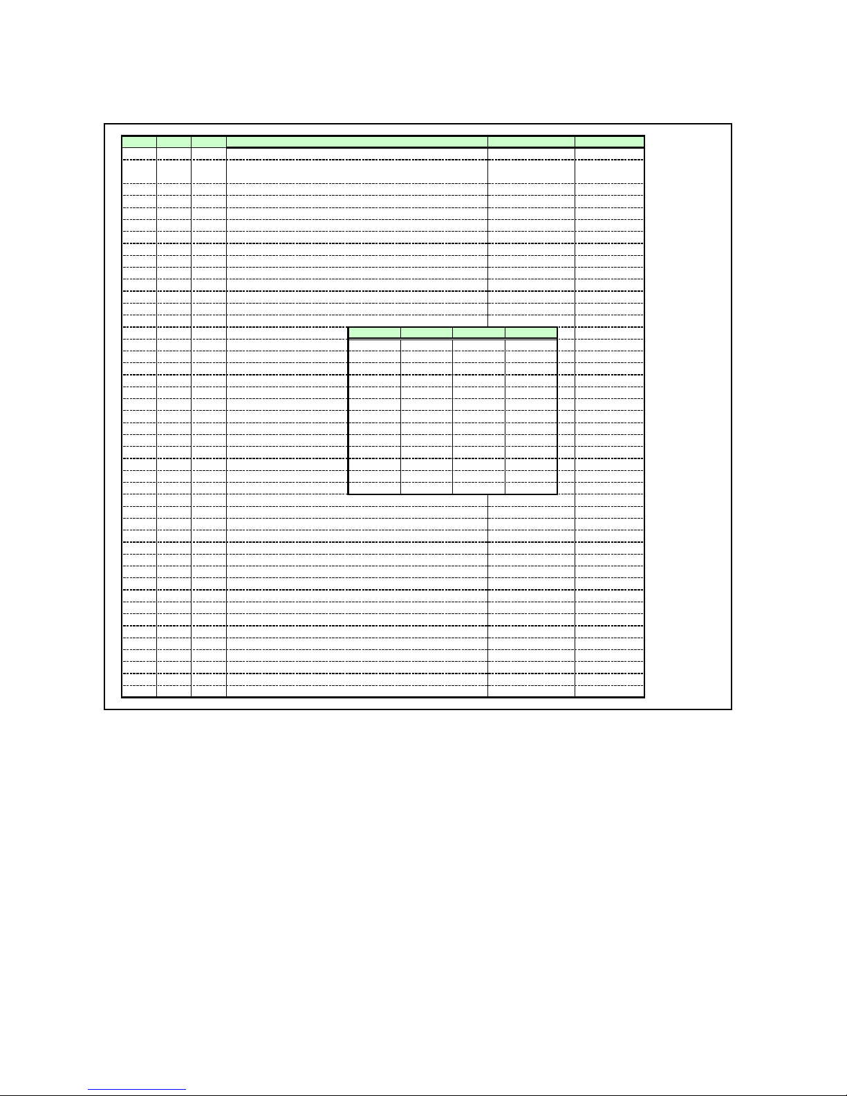
10. Error List
Code
Item
1 0001 e BAD_SEQUENCE Communication sequence error
2
3 0003 e INVALID_MODE
4
5
6 - i BUSY
7 000A e INVALID_PARAMETER
8
9- w
10
11 E0XX e COMMUNICATION_ERROR
12 200X e INVALID_SOURCE (****)
13
14 -
15
16
※
※
TYPE
0002
e
0004
e
0005
e
000B
e
F001
e
2010
e
201X e INVALID_SIGNAL (****)
i
i
i
0801
e
0802
1001 e TERMINAL_OUT
1002 e NO_LOGO_CAPTURED
1003
e
203X e INVALID_RESOLUTION (***) The input signal resolution is not correct.
The error code is expressed as a four-digit hexadecimal character string. ‘X’ is a number from ‘0’ to ‘9’ or letter from ‘A’ to ‘F’.
Errors with the newer item numbers have higher priority. (When there is more than one error, the highest level error is returned. However, error priority is
the same within the same item number.)
Error character string Error description
Wait until the response is received to send the
INVALID_COMMAND Command is invalid (undefined).
INVALID_FORMAT The command format is incorrect.
NOT_POWER_SUPPLIED Power is not being supplied.
JOB_TIMEOUT SX50 internal processing has timed out. Resend the command.
USER_COMMAND_VERSION_IS_UPDA
TED
SYSTEM (UNKNOWN) An internal error occurred. Resend the command.
NO_SIGNAL There is no signal input.
BUSY (NOW_SETTING) Signal setting (detection) is in progress.
BUSY
(POWER_MANAGEMENT_READY)
BUSY (INTERNAL_PROCESS) Heavy processing is in progress.
INVALID_VALUE
IP_NOT_AVAILABLE
The designated command cannot be
executed in this mode.
Transition between states or processing is in
progress in the SX50.
The parameter (type) is invalid (undefined).
This includes the case when the number of
parameters is incorrect.
The user command version is being updated.
A communication protocol violation occurred
in the projector.
This cannot be executed with the current input
source.
The current input source is indicated in
parentheses.
This cannot be executed with the current input
signal.
The current input signal is indicated in
parentheses.
Preparing to switch to power management
standby.
Numerical parameters are invalid or outside
the range.
The input cannot be selected since the
terminal is set to output.
Processing cannot be executed since the user
image is not registered.
IP conversion cannot be performed. Change to the correct input signal.
command.
Send the correct command.
Switch the mode using the REMOTE or
LOCAL command.
Send in the correct command format.
Use the POWER ON command to turn on the
power.
Wait until the power supply state changes to
“ON”, “OFF”, or “PMM”.
Use the correct parameter(s).
Use GET COMVER to obtain the latest user
command version.
Resend the command.
Change the input source.
Input the signal.
Change the input signal.
Wait until the processing is completed.
Use the RANGE command to obtain the
parameter range, and then use a parameter
within the range.
Use the TERMINAL command to set the
terminal to input, and then select the input
again.
Register the user image.
Change to the correct resolution of the input
signal.
Remedy

11. Miscellaneou
s
Use the remote control emulation function (RC command) in Local mode for the following functions.
No display NOSHOW
Freeze screen FREEZE
Digital zoom DZOOM_P, DZOOM_M
Presentation timer P_TIMER
Spotlight function SPOT
Function RC command parameter
n
App
endix 1 Reset Item
s
g
g
A
g
t
C
gs
n
d
n
p
t
A
e
g
t
p
k
f
t
ge
m
t
e
g
All System Image Item Reset setting
●
●
●●
●●
●●
●●
●●
●●
●●
●●
●●
●●
●●
●●
●●●
●●●
●●●
●●●
●●●
●●●
●●●
●●●
●●●
●●●
●●●
●●●
●●●
●●
●●
●●
●●
●
●
●
●
●
●
●
●
●
●
●
●
●
●
●
●
●
●
●
●
●
●
●
Input source switchin
Toggle button recordin
RGB manual for input signal settin
Input signal selec
Input signal select P
Screen settin
Menu display positio
Logo included/not include
Logo position
Screen when nothing show
No signal screen
Screen at startu
Image flip H/V
Image mode
STANDARD PRESEN CINEMA SRGB
Brightness
Contras
Sharpness
Gamma
Dynamic gamma
Screen color correction
Screen color correction va
dvanced color adjustme
NORMAL
0, 0, 0
NOCORRECT
6-axis color adjust valu
Lamp mode
NORMAL
Color saturation
Color balance
Progressive
Terminal settin
Power managemen
Bee
Key loc
Password on/of
Password tex
Remote control
Langua
Menu category ite
Last spotligh
Spotlight OSD position
Volume
Keyston
P-Timer
Mute
Lamp ready indicator off fla
0
00
0
0
0
0, 0
0
0
1111
000
0
0
0
NORMAL
0, 0, 0
NOCORRECT
0, 0
NORMAL
0
0 0
A-RGB2 INPUT
C1:DRGB C2:ARGB2 -----------V :VIDEO
AUTO SEL
not selected -----------FULL ASPECT
CENTER -----------not included -----------CENTER LOGOPOS
BLACK NOSHOW
BLUE NOSIG
CANON PJON
NONE IMAGEFLIP
STANDARD IMAGE
0
0
0
0
NORMAL
0, 0, 0
NOCORRECT
0, 0
SILENT
NORMAL
0, 0, 0
NOCORRECT
NORMAL
0
IN TERMINAL
OFF PMM
1 BVOL
OFF KEYLOCK
OFF -----------none -----------CH1 RCCH
ENG LANG
not selected -----------circle(large) -----------Initial position ------------
10 AVOL
0,0 (HKS,VKS) HKS, VKS
0 -----------OFF MUTE
off ------------
0, 0
Reference command
BRI
0
0
0
0
0
0
CONT
SHARP
GAMMA
DGAMMA
WB
WBRGB
ACADJUST
6AXR~Y
LAMP
SAT
HUE
PROG

e
e
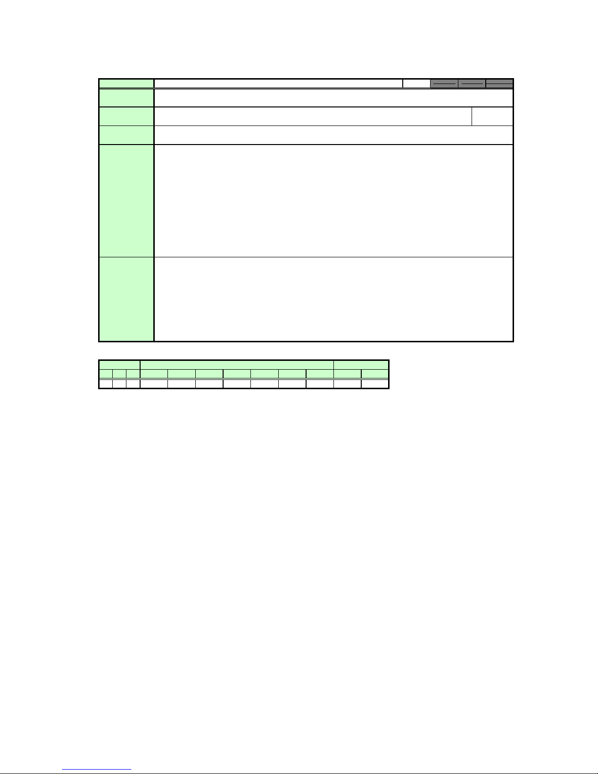
Commands
Function
REMOTE Mode
Switch to Remote mode
Control
Setting
eferenc
Parameter
Response
Description
Example
None
An “i:OK” is returned after switching to the mode is successful.
This switches to Remote mode.
During Remote mode, all buttons are disabled except for the front panel and remote control POWER button.
(1)
In Local mode, this command can be used in any projector state.
(2)
If a REMOTE command is received for switching to Remote mode while power management is in standby, th
(3)
Power On (lamp on) state is activated unconditionally.
Except for RC and MAIN, the control commands can be used in Remote mode only.
(4)
(RC and MAIN can be used in Local mode only.)
The following projector modes and settings are all canceled when this command is executed.
(5)
• Digital zoom
• Presentation timer display
• Spotlight display
• Screen temporary off (NoShow)
• Freeze image (Freeze)
• Commands being executed
The current mode can be viewed with the GET command.
(6)
Mode switching
> REMOTE
< i:OK
Mode viewing
> GET MODE or ?MODE
< g:MODE=LOCAL
*Commands are indicated by “>”, and responses are indicated by “<”.
Supported Command States
Power supply
OFF ON PM
○○○
D-RGB A-RGB1
○
A-RGB2 Comp
○ ○
Input
○○ ○
S-Video None Remote Local
Video
Mode
○○○
e
Commands
Function
LOCAL Mode
Switch to Local mode
Control
Setting
eferenc
Parameter
Response
Description
None
An “i:OK” is returned after switching to the mode is successful.
This switches to Local mode.
(1)
Only the following commands can be used during Local mode.
•REMOTE
•LOCAL
•RC
•MAIN
•GET MODE
(2)
This command can be used in any projector state.
(3)
The current mode can be viewed with the GET command.
Example
Mode switching
> LOCAL
< i:OK
Mode viewing
> GET MODE or ?MODE
< g:MODE=LOCAL
*Commands are indicated by “>”, and responses are indicated by “<”.
Supported Command States
Power supply
OFF ON PM
○○○
D-RGB A-RGB1 A-RGB2 Comp Video S-Video None Remote Local
○○○○○○○○○
Input
Mode
e
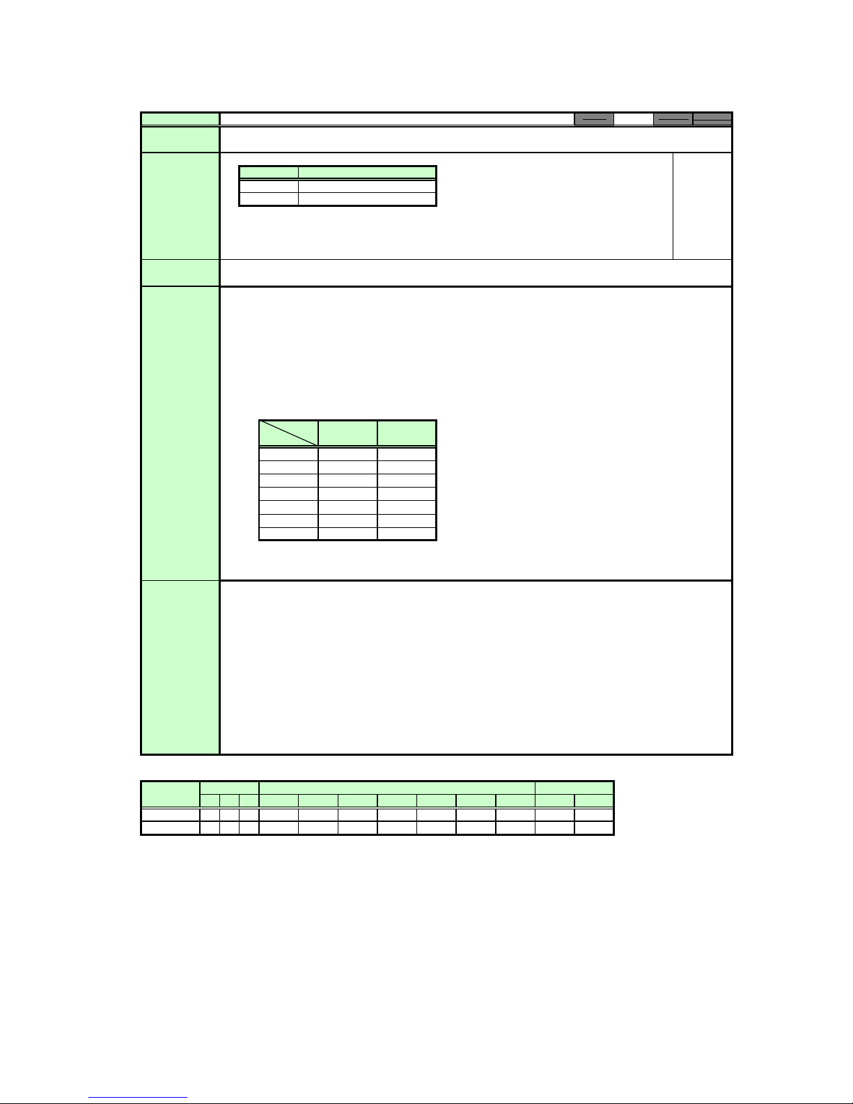
Commands
Function
POWER Mode
This controls the power supply.
Control
Setting
Referenc
Parameter
Response
Description
Parameter Meaning
ON Power ON
OFF Power OFF
The RANGE command can be used to obtain the parameters that can be set at that time.
An “i:OK” is returned after setting is successful.
This performs ON/OFF control of the power supply.
(1)
This command is identical to pressing the POWER button on the remote control or main unit.
(2)
After sending this command, use GET POWER to obtain the power supply state at regular
intervals, and check that it is in the controlled state (off or on).
(3)
The table below shows the POWER command responses according to the power supply state.
POWER Command Responses by Power Supply State
Command
Status
Off
Off→lit
Lamp on
Lit→off
Lit→standby
Standby
Standby→lit
The current mode can be viewed with the GET command.
(4)
POWER ON POWER OFF
○○
○○
○○
△○
○○
○
○
○○
○: i:OK
△: i:BUSY
ID
Example
Control
>
POWER ON
<
i:OK
Reference
> GET POWER or ?POWER
< g:POWER=OFF
Obtain settable parameters
> RANGE POWER
< r:POWER=I,ON,OFF
*Commands are indicated by “>”, and responses are indicated by “<”.
Supported Command States
Parameter Power supply
※When the power supply state is in the process of switching, an “i:BUSY” reply may be sent.
ON
OFF
OFF ON PM
○○○
○○○
D-RGB A-RGB1
○
○
○
○
A-RGB2 Comp
Input Mode
Video
S-Video None Remote
○ ○
○○
○
○○○ ×
○
○○○ ×
Local