

SUPER G3
FAX BOARD-J1
REVISION 0
JUNE 2001
COPYRIGHT© 2001 CANON INC. 200 CANON SUPER G3 FAX BOARD-J1 REV .0 JUNE 2001 PRINTED IN U.S .A.
FY8-13HD-000

Application
This manual has been issued by Canon Inc. for qualified persons to learn technical
theory, installation, maintenance, and repair of products. This manual covers all
localities where the products are sold. For this reason, there may be information in this
manual that does not apply to your locality.
Corrections
This manual may contain technical inaccuracies or typographical errors due to
improvements or changes in products. When changes occur in applicable products or in
the contents of this manual, Canon will release technical information as the need arises.
In the event of major changes in the contents of this manual over a long or short period,
Canon will issue a new edition of this manual.
The following paragraph does not apply to any countries where such provisions are
inconsistent with local law.
Trademarks
The product names and company names used in this manual are the registered
trademarks of the individual companies.
Copyright
This manual is copyrighted with all rights reserved. Under the copyright laws, this
manual may not be copied, reproduced or translated into another language, in whole or
in part, without the written consent of Canon Inc.
COPYRIGHT © 2001 CANON INC.
Printed in U.S.A.
Imprimé au U.S.A.
Caution
Use of this manual should be strictly supervised to avoid disclosure of confidential information.
COPYRIGHT© 2001 CANON INC. 200 CANON SUPER G3 FAX BOARD-J1 REV .0 JUNE 2001 PRINTED IN U .S.A.
INTRODUCTION
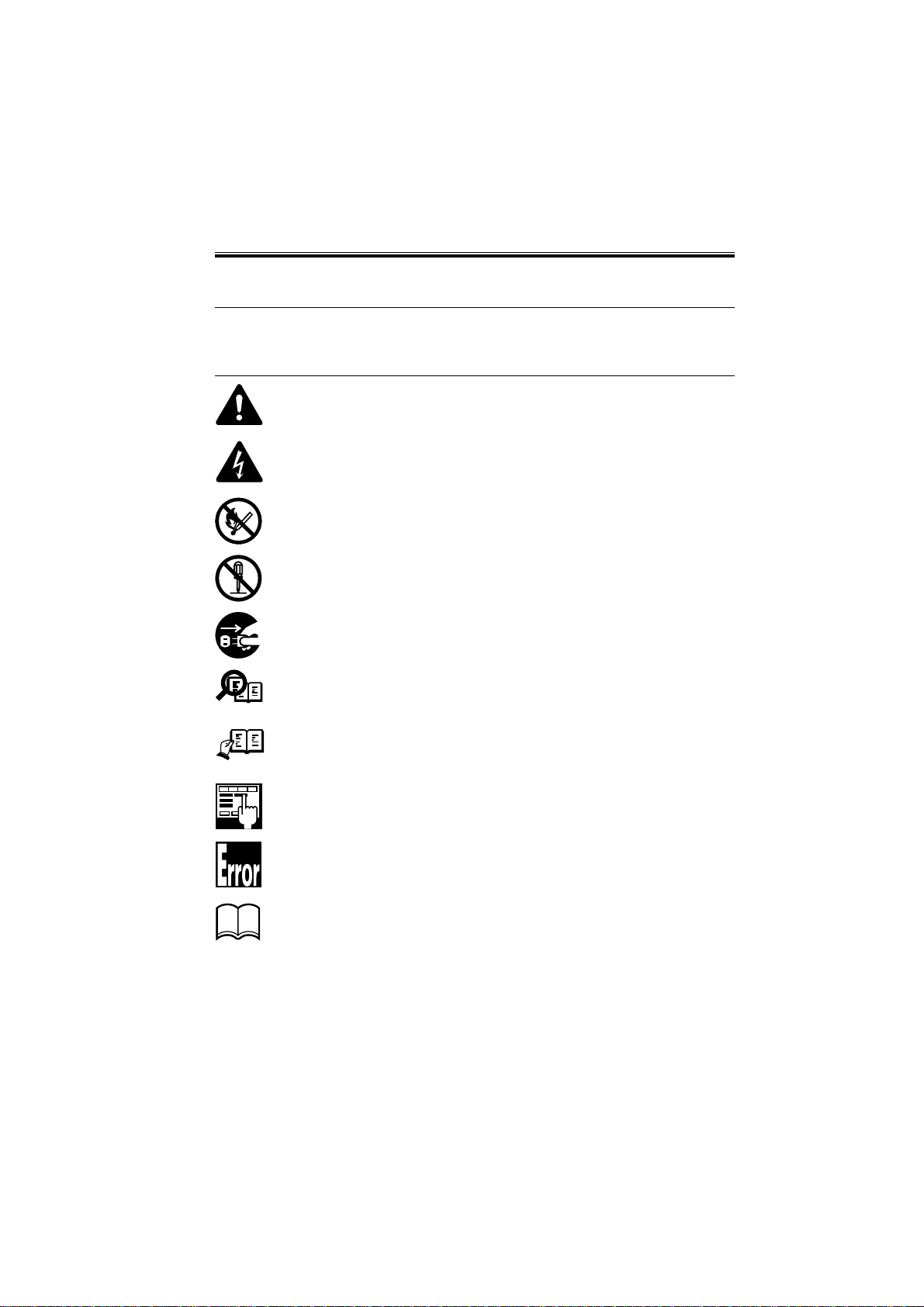
1 Symbols Used
This documentation uses the following symbols to indicate special information:
Symbol Description
Indicates an item of a non-specific nature, possibly classified as Note, Caution,
or W arning.
Indicates an item requiring care to avoid electric shocks.
Indicates an item requiring care to avoid combustion (fire).
Indicates an item prohibiting disassembly to avoid electric shocks or problems.
Indicates an item requiring disconnection of the power plug from the electric
outlet.
Indicates an item intended to provide notes assisting the understanding of the
Memo
topic in question.
REF.
COPYRIGHT
©
Indicates an item of reference assisting the understanding of the topic in question.
Provides a description of a service mode.
Provides a description of the nature of an error indication.
Refers to the Copier Basics Series for a better understanding of the contents.
2001 CANON INC. 2000 2000 2000 2000 CANON SUPER G3 FAX BOARD-J1 REV.0 JUNE 2001
i

INTRODUCTION
2 Outline of the Manual
This Service Manual contains basic information needed to service the G3 FAX Board designed for installation to the iR2200/iR2800/iR3300 in the field, conducted for the purpose
of maintaining its product quality and a specific level of performance. For descriptions on
how to use the iR2200/iR2800/iR3300, see the separately prepared Service Manual.
This Service Manual consists of the following chapters:
Chapter 1 Outline: features, specifications, system configura-
tion, list of user modes
Chapter 2 Basic Operation: functional construction, outline of electrical
circuitry, power supply
Chapter 3 Troubleshooting: points to Note for Troubleshooting, upgrad-
ing
Chapter 4 Installation: installation
Chapter 5 Service Mode: using service mode, list of service modes
Chapter 6 Error Code: list of error codes, main causes, list of mea-
sures
Appendix: curcuit diagram
The descriptions are updated from time to time to reflect product improvements, and major changes are communicated in the form of Service Information bulletins.
All service persons are expected to familiarize themselves with the contents of this Service Manual and Service Information bulletins and acquire a level of knowledge and skill
required to promptly respond to the needs of the field.
This Service Manual does not provide detailed descriptions on how to use
REF.
the Board or detailed information on user reports. See the separately prepared booklet.
The detailed explanations on SSSW/parameters are limited to those used in
association with the Board; for others, see the separately prepared "G3 Facsimile Service Data Handbook" (Rev.0; HY8-23A1-000).
As for error codes, full explanations are on those newly added to the Board
or those for which measures specific to the Board are offered; for others,
see the separately prepared "G3 Facsimile Error Code List" (Rev.1; HY823A0-010).
ii
COPYRIGHT
©
2001 CANON INC. 2000 2000 2000 2000 CANON SUPER G3 FAX BOARD-J1 REV.0 JUNE 2001

INTRODUCTION
The following rules apply throughout this Service Manual:
1. Each chapter contains sections explaining the purpose of specific functions and the relationship between electrical and mechanical systems with reference to the timing of
operation.
In the diagrams,
accompanies the symbol
represents the path of mechanical drive; where a signal name
, the arrow indicates the direction of the electric signal.
The expression “turn on the power” means flipping on the power switch, closing the
front door, and closing the delivery unit door, which results in supplying the machine
with power.
2. In the digital circuits, ‘1’ is used to indicate that the voltage level of a given signal is
“High,” while ‘0’ is used to indicate “Low.” (The voltage value, however, differs from
circuit to circuit.) In addition, the asterisk (*) as in “DRMD*” indicates that the
DRMD signal goes on when ‘0’.
In practically all cases, the internal mechanisms of a microprocessor cannot be
checked in the field. Therefore, the operations of the microprocessors used in the machines are not discussed: they are explained in terms of from sensors to the input of the
DC controller PCB and from the output of the DC controller PCB to the loads.
The descriptions in this Service Manual are subject to change without notice for product
improvement or other purposes, and major changes will be communicated in the form of
Service Information bulletins.
All service persons are expected to have a good understanding of the contents of this Service Manual and all relevant Service Information bulletins and be able to identify and isolate
faults in the machine.
COPYRIGHT
©
2001 CANON INC. 2000 2000 2000 2000 CANON SUPER G3 FAX BOARD-J1 REV.0 JUNE 2001
iii

CONTENTS
Contents
CHAPTER 1 OUTLINE
1 Outline .............................................. 1-1
2 Specifications ................................... 1-2
3 List of USER Modes ........................ 1-4
3.1 User Mode>Custom Fax Settings
................................................... 1-4
CHAPTER 2 BASIC OPERATION
1 G3 Fax Control PCB ........................ 2-1
1.1 G3 Fax Control PCB Block
Diagram ..................................... 2-1
1.2 Components of the G3 Fax
Control PCB............................... 2- 1
2 NCU PCB ......................................... 2-3
2.1 Block Diagram of the NCU
PCB ............................................ 2-3
CHAPTER 3 TROUBLESHOOTING
1 Points to Note for Troubleshooting.. 3-1
1.1 When Turning Off the Main Power
................................................... 3-1
1.2 Points to Note When Changing
Service Mode Settings ............... 3-1
1.3 Points to Note When Accessing the
DC Controller PCB .................... 3-1
3.2 User Mode>Report Settings ...... 1-5
3.3 User Mode>System Settings>
Communication Settings............1-6
2.2 Functions of the NCU PCB ....... 2- 3
3 Off-hook detection PCB................... 2-4
3.1 Block Diagram of the Off-hook
detection PCB ............................ 2-4
3.2 Functions of the Off-hook detection
PCB ............................................ 2-4
4 Wiring Diagram................................ 2 - 5
5 Signals .............................................. 2-6
1.4 Backing Up the Address Book... 3-2
2 Problems at Time of Installation ...... 3-3
3 Common Problems ........................... 3 -4
4 Upgrading......................................... 3-5
CHAPTER 4 INSTALLATION
1 Installation ........................................ 4-1
1.1 Checking the Contents ............... 4- 1
1.2 Before Starting the Work ........... 4-2
1.3 Installation to the Host Machine 4- 2
1.4 Connecting to the Telephone Line
................................................... 4-7
iv
COPYRIGHT
©
2001 CANON INC. 2000 2000 2000 2000 CANON SUPER G3 FAX BOARD-J1 REV.0 JUNE 2001
1.5 Selecting the Type ...................... 4-8
1.6 Setting Telephone Number and the
Type of Line ............................... 4-8
1.7 Checking the Operation of FAX
Functions.................................... 4-9

CHAPTER 5 SERVICE MODE
1 Service Mode ................................... 5-1
1.1 Outline ....................................... 5-1
1.2 Using Service Mode .................. 5-2
1.3 Guide to the Keys....................... 5-3
2 List of Service Mode Items .............. 5-4
3 Using the Bit Switches(#1SSSW) .... 5-7
4 Menu Switch Setting (#2 MENU) . 5-20
5 Setting V arious Parameters
(#3 NUMERIC Param.) ................. 5-22
6 Selecting the Country (#5 TYPE) .. 5-26
7 Setting Printer Functions
(#7 PRINTER) .............................. 5-26
7.1 Service Software Switches....... 5-26
7.2 NUMERIC Param.
(numeric parameter setting) .... 5-28
8 Initializing the Settings
(#8 CLEAR) ................................... 5-29
9 Test Mode (#9 TEST) ..................... 5-30
10 Service Report ................................ 5-37
CHAPTER 6 ERROR CODES
1 Generating Service Error Codes ......6-1
2 Outline of Error Codes ..................... 6-2
3 List of Error Codes........................... 6-3
4 Causes of and Remedies for Newly
CONTENTS
9.1 MODEM T est........................... 5-31
9.1.1 Relay Test .......................... 5-31
9.1.2 Frequency Test (FREQ) ..... 5-32
9.1.3 G3 Signal Transmission Test
(G3 Tx) .............................. 5-33
9.1.4 DTMF Transmission Test .. 5-34
9.1.5 V.34 G3 signal Transmission
Test (V34G3Tx)................. 5-35
9.2 Function Test............................ 5-36
9.2.1 4800bps Signal Transmission
Test..................................... 5-36
10.1 System Data List ...................... 5-37
10.2 System Dump List ................... 5-38
10.3 Error Transmission Report.......5-41
Added Error Codes........................... 6-8
APPENDIX
1.1 G3 FAX CONTROL PCB
(100V/120V)(1/8) ..................... A-1
1.2 OFF-HOOK DETECTION PCB
.................................................. A-9
COPYRIGHT
©
2001 CANON INC. 2000 2000 2000 2000 CANON SUPER G3 FAX BOARD-J1 REV.0 JUNE 2001
1.3 NCU PCB (120V) (1/2) .......... A-10
1.4 G3 MODULAR PCB (120V) . A-13
v

CHAPTER 1
OUTLINE
COPYRIGHT
©
2001 CANON INC. 2000 2000 2000 2000 CANON SUPER G3 FAX BOARD-J1 REV.0 JUNE 2001
CHAPTER 1 OUTLINE
1 Outline
The Board combines image processing functions and telephone-based communication
functions to enable a digital copier to operate as a highly functional fax-in-one machine.
It transmits images at a speed of 33.6 kbps max., taking advantage of a V.34-standard mo-
dem recommended under ITU-T.
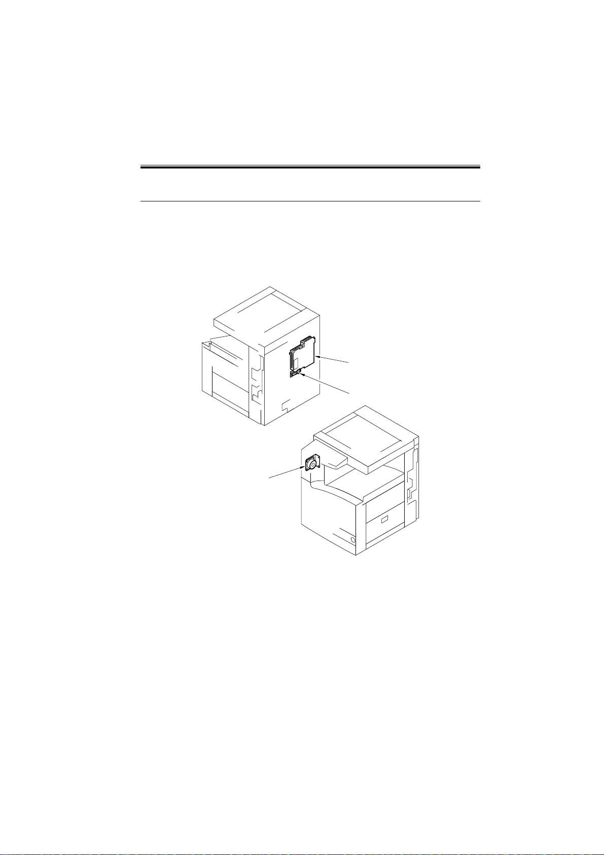
[1]
[2]
[1] Super G3 FAX Board-J1
[2] Off-hook detection Unit
[3] Speaker Unit
COPYRIGHT
©
2001 CANON INC. 2000 2000 2000 2000 CANON SUPER G3FAX BOARD-J1 REV.0 JUNE 2001
[3]
F01-101-01
1-1

CHAPTER 1 OUTLINE
2 Specifications
Lines Used
• subscriber line (PSTN)
Method of Modulation
G3 image signal ITU-T V.27ter (2.4Kbps, 4.8Kbps)
ITU-T V.29 (7.2Kbps, 9.6Kbps)
ITU-T V.17 (TC 7.2Kbps, TC9.6Kbps, 12Kbps, 14.4Kbps)
ITU-T V.34 (2.4Kbps, 4.8Kbps, 7.2Kbps, 9.6Kbps,
12Kbps, 14.4Kbps, 16.8Kbps, 19.2Kbps,
21.6Kbps, 24Kbps, 26.4Kbps, 28.8Kbps,
31.2Kbps, 33.6Kbps)
G3 procedure signal
Speed of Transmission
33.6Kbps, 31.2Kbps, 28.8Kbps, 26.4Kbps, 24Kbps, 21.6Kbps, 19.2Kbps
16.8Kbps, 14.4Kbps, 12Kbps, TC9.6Kbps, TC7.2Kbps, 9.6Kbps,
7.2Kbps, 4.8Kbps, 2.4Kbps
equipped with auto fall-back function
Method of Coding
JBIG, MMR, MR, MH
ITU-T V.21 No.2 (300bps)
ITU-T V.8, V34 (300bps, 600bps, 1200bps)
G3-Unique Abbreviation
None
Modem IC
Conexant FM336
Error Correction
ITU-T ECM method
Specifications for the Reader Unit
Size of Originals for Transmission
A3, A4, A4R, A5R, B4, B5, B5R
LTR, LTRR, LGL, 11×17, STMT, STMTR
DADF-H1 in use: transmission of double-sided originals possible
1-2
COPYRIGHT
©
2001 CANON INC. 2000 2000 2000 2000 CANON SUPER G3 FAX BOARD-J1 REV.0 JUNE 2001

CHAPTER 1 OUTLINE
Density of Scanning Lines
Standard 8dot/mm×3.85 lines/mm
Fine 8dot/mm×7.7 lines/mm
Super Fine 8dot/mm×15.4 lines/mm
Ultra Fine 16dot/mm×15.4 lines/mm
Reproduction of Halftone
PD method (same as when making copier; 256 gradations)
DONE Stamp
if DADF-H1 is in use ink color: Pink
may be at end of transmission or of reading (by selection)
Specifications for the Recording Unit
Maximum reception size A3(297×420mm)
Density of scanning lines 600×600dpi
Trial shot yes
Memory Specifications
Image memory 3,700 pages (approx; using Canon FAX standard Char t No. 1)
memory type hard disk (about 4 GB of image area)
Method of Storage JBIG
Other Specifications
ECM Function
yes
Polling Function
yes
Memory Box Function
yes
Password Reception
yes
Transfer Function
yes
Telephone Number Notice Function (as source)
yes
User Abbreviation Notice Function
yes
Display Language Switch Function
yes (among installed language modules)
Remote UI (RUI) function
yes
check on communications history, check on received fails, registration of various
user mode settings
import/export of electrical telephone directory
COPYRIGHT
©
2001 CANON INC. 2000 2000 2000 2000 CANON SUPER G3FAX BOARD-J1 REV.0 JUNE 2001
1-3

CHAPTER 1 OUTLINE
3 List of USER Modes
3.1 User Mode>Custom Fax Settings
level 1 level 2
1. User Settings Standard key settings: no setting*, Delayed TX, memory box,
sender’s name, RX mode,
Document size, Test Print, Zoom TX.
Unit Telephone #
Unit Name : input mode (Alphabet, other)
Sender’s Names(TTI): input mode (Alphabet, other);
99 items max.
TX Terminal ID: on*, off
on>option setting
image (inside, outside*)
telephone # mark (FAX*, TEL)
Density Control: lighter < > darker; 9 settings
Tel Line Type: Pulse, tone*
Volume Control: alarm Volume: (0 to 8, 4*)
monitor volume: 0 to 8, 4*
standard settings: Store and Initialize possible
2. Store Destinations A many as 200 items 15 addresses each are indicated
(from *001 to *200) per screen, and indexes may be stored
may be stored; for each.
3. TX Settings ECM TX: on*, off
pause time: 1 to 15 sec, 2 sec*
auto redial: on*, off
on>option setting
Redial Times: 1 to 15 times, 2 times*
Redial Interval: 2 to 99 min, 2 min*
TX Error Resend: Error and 1st
page*,All pages, Off
Stamp Document (if DADF-H1 in use)
4. RX Settings ECM RX: on*, off
Received Page Footer: on, off*
*Factory Setting
1-4
COPYRIGHT
©
2001 CANON INC. 2000 2000 2000 2000 CANON SUPER G3 FAX BOARD-J1 REV.0 JUNE 2001

CHAPTER 1 OUTLINE
5. Printer Settings Select Cassette switch A: on*, off
switch B: on*, off
switch C: on*, off
switch D: on*, off
Receive reduction: on*, off
on>option setting
RX Reduction: auto*, Fix, Red.
reduce %: 75, 90*, 95, 97%
reduce direction: ve rti cal/horizontal,
vertical only*
Two-sided Print: on, off*
2-on-1 Log: on, off*
3.2 User Mode>Report Settings
level 1 level 2
1. Custom settings>Fax TX report: on, for error only*, off
yes>Report with TX Image
on*, off
Activity report auto Print every 40 communications:
on*, off
Send/Receive separate:
on, off*
Daily Activity Report Time: on, off*
on>time input
RX report: on, for error only, off*
memory box RX report: on*, off
2. Print List>Fax address book list 1, address book list 2, group Destination list, user’s data
list
*Factory Setting
COPYRIGHT
©
2001 CANON INC. 2000 2000 2000 2000 CANON SUPER G3FAX BOARD-J1 REV.0 JUNE 2001
1-5

CHAPTER 1 OUTLINE
3.3 User Mode>System Settings>Communication Settings
level 1 level 2
1. Send start speed:
33600*/14400/9600/7200/4800/2400bps
2. Receive start speed: 33600*/14400/9600/7200/4800/2400bps
3. Transfer setting: on, off*
on>option setting
Password (optional)
transfer destination
Select Original Unit: on*, off
on>Select address
Print RX Document: on*, off
Transfer Start Time: everyday (5 times), Select Days
(5 times by day of week), off*
Transfer Ending Time: everyday (5 times), Select Days
(5 times by day of week), off*
4. memory Lock setting:
on, off*
on>option setting
Password (optional)
report print: on*, off
memory Lock start time:
every day (5 time), select Days (5 times by day of week),
off*
memory Lock End Time:
every day (5 time), select Days (5 times by day of week),
off*
5. PIN Code Access: on, off*
on>PIN Code Position
Option*, Prefix, Suffix
6. Receive password: 20 characters
*Factory setting.
1-6
COPYRIGHT
©
2001 CANON INC. 2000 2000 2000 2000 CANON SUPER G3 FAX BOARD-J1 REV.0 JUNE 2001

CHAPTER 2
BASIC OPERATION
COPYRIGHT
©
2001 CANON INC. 2000 2000 2000 2000 CANON SUPER G3 FAX BOARD-J1 REV.0 JUNE 2001
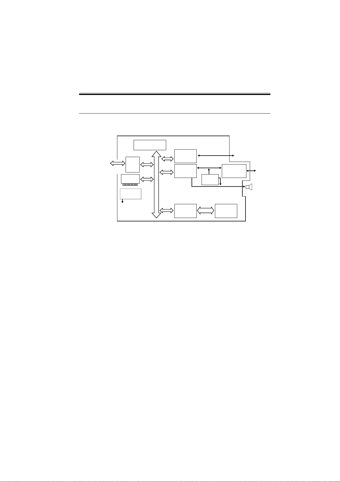
1 G3 Fax Control PCB
1.1 G3 Fax Control PCB Block Diagram
CHAPTER 2 BASIC OPERATION
G3 Fax control PCB
ASIC
PORT IC
(IC16)
MODEM IC
FM336
(IC11)
ASIC
Chip-C
(IC46)
OGMIC
(IC44)
32bit
Analog level
adjustment
circuit
SDRAM
64Mbit
(IC6)
NCU
(CONTROL)
Speaker
Main Controller
PCB
IEEE
1284
ASIC
Chip-D
(IC43)
FLASH
ROM-DIMM
Reset IC
(IC3)
MPU
CHIP-C
CHIP-D
PORT IC
MPU
(IC34)
16
b
i
t
F02-101-01
1.2 Components of the G3 Fax Control PCB
MPU (IC34)
µPD703107GJ-025-UEN (V850E-MA1) from NEC is an MPU used to control the com-
munications exchanged on the line.
It is equipped with a 256K-byte internal ROM and a 10K-byte internal RAM, and is
driven by 3.3 V.
ASIC (IC46)
MB87J1762PFVS from Fujitsu is an ASIC (chip-D) used for JBIG coding/decoding and
SDRAM control. A 64M-bit SDRAM is connected to it.
NCU
(LINE)
COPYRIGHT
©
2001 CANON INC. 2000 2000 2000 2000 CANON SUPER G3FAX BOARD-J1 REV.0 JUNE 2001
2-1

CHAPTER 2 BASIC OPERATION
ASIC (IC43)
µPD82870GD-001-LML from NEC used for ASIC (chip D) serves to control the bi-directional, parallel communications of the IEEE1284 cable (interface with the main controller
PCB), to control the chips around the MPU, to process detection of off-hook state, and to
process CI counter operations.
G3 FAX Control DIMM Slot (J11)
The 16M-bit flash ROM DIMM installed to this slot contains a program used to control
communications on an analog telephone line. The DIMM may be upgraded by downloading
using a Service Support Tool or by replacement.
ASIC (IC16)
µPD65882GC-015-8EU from NEC is an ASIC (port IC), and is used to control the NCU
and various ports such as for speakers.
SDRAM (IC6)
The 64M-bit SDRAM serves as memory for coding/decoding of image data for transmission/reception or as a work area for the MPU.
RESET IC (IC3)
The reset IC is used when resetting the MPU of the Board, as when the power is tuned on
or when the voltage of the power drops.
MODEM IC (IC11)
FM336 from CONEXANT is a modem used for G3 modulation as prescribed by ITU-T
V.17, V.21, V.27ter, V.29, and V.34. At time of reception, the received data from the line is
subjected to G3 demodulation as prescribed by ITU-T V.17, V.21, V.27ter, V.29, and V.34.
OGMIC (IC44)
OGMIC is used to reproduce voice messages.
2-2
COPYRIGHT
©
2001 CANON INC. 2000 2000 2000 2000 CANON SUPER G3 FAX BOARD-J1 REV.0 JUNE 2001

CHAPTER 2 BASIC OPERATION
2 NCU PCB
2.1 Block Diagram of the NCU PCB
NCU PCB
2-line to 4-line conversion circuit
Line voltage conversion circuit
Dial pulse generation circuit
Off-hook detection circuit
F02 -201-01
2.2 Functions of the NCU PCB
2-Line to 4-Line Conversion Circuit
It converts signals from a 2-line telephone line into transmission signals and reception
signals for a 4-line signal line. In addition, it prevents transmission signals from the modem from invading the reception circuit.
Dial Pulse Generation Circuit
The dial pulse generation circuit generates dial pulses by turning on and off the relay in
the circuit using control signals from the G3 fax control PCB, thereby enabling the fax
board to transmit dial signals using the dial line.
Off-Hook Detection Circuit
It identifies the condition of the telephone or the handset (option) connected to the telephone terminal as being off- or on-hook in relation to the DC current flowing into it.
Circuit Voltage Conversion Circuit
The primary side of the NC board circuit is controlled by means of a line voltage of +48
VDC; the DC component is cut out using a capacitor, thereby converting only the audio
signals in voltages of a model level.
COPYRIGHT
©
2001 CANON INC. 2000 2000 2000 2000 CANON SUPER G3FAX BOARD-J1 REV.0 JUNE 2001
2-3

CHAPTER 2 BASIC OPERATION
3 Off-hook detection PCB
3.1 Block Diagram of the Off-hook detection PCB
From
composite power
supply PCB
+24V
From
main controller
PCB
5V all-day
voltage
J713
J712
3.2 Functions of the Off-hook detection PCB
Power Supply Circuit Used to Detect an Extension
To detect the connection of an extension, the Off-hook detection PCB generates a DC
voltage of +48 V to supply to the extension terminal. A transformer is used to separate the
primary side and the secondary side by an electrical means.
All-Day Power Supply Circuit
The main controller circuit generates all-day 5 VB from all-night +3.3 VB. To operate the
FC detection circuit of the G3 fax control PCB at all times, the +5 VB voltage is sent to
the G3 fax control PCB by way of the Off-hook detection PCB.
Off-hook detection PCB
Power supply circuit for
detection of extension
telephone
All-day power supply
relay circuit
F02-301-01
J714
J715
supplies voltage for
detection of off-hook
state
5V all-day power
supply
2-4
COPYRIGHT
©
2001 CANON INC. 2000 2000 2000 2000 CANON SUPER G3 FAX BOARD-J1 REV.0 JUNE 2001
4 Wiring Diagram
Main
Controller
PCB
J31
1--40
DIMMROM
1--72
J11
G3 fax control PCB
J106
Modular PCB
1--50
J912
CHAPTER 2 BASIC OPERATION
J911
1--7
J10
J4
1--5
1--2
J1005
COPYRIGHT
©
1--40
J714
Off-hook detection.
1--2
1--14 1--2
J104
J105
1--14
J103
J718 J713
1--3
J715
J712
1--2
J102
1--2
1--4
Main
Controller
PCB
J1059
1--6
J101
1--23
Supply PCB
Main
power
J204
1--6
NCU PCB
J2
1--23
1--10 1--2 1--2
J900 J9020
Composite
Supply PCB
Power
J124
Speaker Arrester
J1
F02-401-01
2001 CANON INC. 2000 2000 2000 2000 CANON SUPER G3FAX BOARD-J1 REV.0 JUNE 2001
J2002
GND
2-5

CHAPTER 2 BASIC OPERATION
5 Signals
G3 fax control PCB (J31)¬ ®Main controller PCB (J1005)
J31 J105 signal Description
A1 A20 FSTROBE host clock
A2 A19 FD0 data signal 0
A3 A18 FD1 data signal 1
A4 A17 FD2 data signal 2
A5 A16 FD3 data signal 3
A6 A15 FD4 data signal 4
A7 A14 FD5 data sing 5
A8 A13 FD6 data signal 6
A9 A12 FD7 data signal 7
A10 A11 FNACK peripheral clock
A11 A10 FBUSY forward ACK signal
A12 A9 FPERROR rev erse ACK signal
A13 A8 FSELECT transfer mode switch signal (H=ECP mode)
A14 A7 FRESET forced reset signal
A15 A6 FOPTIONO board detection signal (H=present)
A16 A5 NC not used
A17 A4 NC not used
A18 A3 GND 3.3V ground
A19 A2 FSPKON speaker ON (L=being generated)
A20 A1 HPDIR not used
B1 B2 0 PWCTL ESS release command signal to fax board (L=ESS release)
B2 B1 9 CICNT pseudo CI control signal
B3 B1 8 NC not used
B4 B1 7 ESSACT ESS release request signal (L=ESS release) for G4
B5 B1 6 FSPOUT line monitor analog output
B6 B1 5 GND 3.3V ground
B7 B1 4 FCID CI/FC/CNG detection signal
B8 B1 3 FOFFHK OFFHOOK signal
A9 B12 BUSDIR bus direction control signal to HOST
B10 B11 NC not used
B11 B10 NC not used
B12 B9 NC not used
B13 B8 GND 3.3V ground
B14 B7 GND 3.3V ground
B15 B6 GND 3.3V ground
B16 B5 GND 3.3V ground
B17 B4 FNSELECT IN 1284 active (H=ECP mode)
B18 B3 FNINT nReverse request
B19 B2 FNFAULT nPeripheral request (L= data from peripheral present)
B20 B1 FNAUTOFD reverse mode control signal
2-6
COPYRIGHT
©
2001 CANON INC. 2000 2000 2000 2000 CANON SUPER G3 FAX BOARD-J1 REV.0 JUNE 2001

CHAPTER 2 BASIC OPERATION
G3 fax control PCB (J101) ¬ ®NCU PCB (J2)
J101 J2 signal Description
1 6 AGND analog ground
2 5 NC not used
3 4 +12V relay power supply
4 3 ANLGIN line monitor signal
5 2 TX 4-line transmission signal
6 1 RX 4-line reception signal
G3 fax control PCB (J102)¬ ®NCU PCB (J1)
J102 J1 Signal Description
1 1 DGND digital ground
2 2 BIT2 for future use
3 3 BIT1 for future use
4 4 BIT0 for future use
5 5 LPL2 line polarity signal 2 (H=L2 positive)
6 6 LPL1 line polarity signal 1 (H=L1 positive)
7 7 HOOK2 external telephone off-hook detection signal (H=off-hook)
8 8 HOOK1 extension telephone off-hook detection signal (H=off-hook)
9 9 CI0R CI1 and CI2 OR signal (H=C1 present)
10 10 CI2 CI detection signal 1 (H=CI present)
11 11 CI1 CI detection signal 2 H=C1 present)
12 12 LPRD polarity reversal detection relay drive signal (H=ON)
13 13 DCD DC relay drive signal (H=ON)
14 14 CMLD CML relay drive signal (H=ON)
15 15 HRD H relay drive signal (H=ON)
16 16 PRD P relay drive signal (H=ON)
17 17 SRD S relay drive signal (H=ON)
18 18 VHGND VH ground
19 19 VHGND VH ground
20 20 VH off-hook detection power supply
21 21 VCC ESS 3.3 V all-time drive power supply
22 22 +3.3V logic drive voltage
23 23 DGND digital ground
COPYRIGHT
©
2001 CANON INC. 2000 2000 2000 2000 CANON SUPER G3FAX BOARD-J1 REV.0 JUNE 2001
2-7

CHAPTER 2 BASIC OPERATION
G3 fax control PCB (J104) ¬ ®Composite power supply PCB (J124), Off-hook de-
tection PCB (J715)
J104
J124/J715
signal Description
1 - GND4 not used
2 - +12V not used
3 1(J124) GND0 3.3V digital ground
4 2(J124) GND0 3.3V digital ground
5 3(J124) +3.3V 3.3V power supply (at time of ESS, OFF)
6 4(J124) +3.3V 3.3V power supply (at time of ESS, OFF)
7 5(J124) GND3 3.3VS digital ground
8 6(J124) +3.3VS ESS 3.3V all-time drive pow er supply
9 7(J124) GND2 5V digital ground
10 8(J124) GND2 5V digital ground
11 9(J124) +5V 5V power supply (at time of ESS, OFF)
12 10(J124) +5 V 5V p ow e r supply (at time of ESS, OFF)
13 1(J715) +5VS ESS 5V all-time drive power supply
14 1(J715) GND1 5VS analog ground
G3 fax control PCB (J105)¬ ®Relay connector to speaker
J105 SPK signal Description
1 1 SPKR1 Speaker output
2 2 SPKR2 Speaker output
NCU PCB (J3)¬ ®Modular PCB (J911)
J3 J911 signal Description
7 1 T1 not used
6 2 T2 not used
5 3 NC not used
4 4 L1 telephone line connection
3 5 L2 telephone line connection
2 - - not used
1 - - not used
NCU PCB (J4)¬ ®Off-hook detection PCB (J714)
J4 J714 signal Description
1 1 VH off-hook detection power supply
2 2 OVH ground
2-8
COPYRIGHT
©
2001 CANON INC. 2000 2000 2000 2000 CANON SUPER G3 FAX BOARD-J1 REV.0 JUNE 2001

CHAPTER 2 BASIC OPERATION
Off-hook detection PCB (J712)¬ ®Main controller PCB (J1059)
J712 J1059 signal Description
1 1 OVA +5V all-day power ground
2 2 5VB +5V all-day power supply
3 3 OVD not used
4 4 CICNT not used
Off-hook detection PCB (J713)¬ ®Main power supply PCB (J204)
J713 J204 signal Description
1 9 24VU3 +24V power supply
2 10 OVU3 +24V ground
Off-hook detection PCB (J715)¬ ®G3 fax control PCB (J104)
J715 J104 signal Description
1 13 5VB +5V all-day power supply
2 14 OVA +5V all-day ground
Off-hook detection PCB (J718)
not used
Modular PCB (J912)¬ ®Modular Cable
J912 Cable signal Description
1 - L22 not used
2 - L21 not used
3 - L12 telephone line 1 connection
4 - L11 telephone line 1 connection
5 - T2 not used
6 - T1 not used
COPYRIGHT
©
2001 CANON INC. 2000 2000 2000 2000 CANON SUPER G3FAX BOARD-J1 REV.0 JUNE 2001
2-9

CHAPTER 3
TROUBLESHOOTING
COPYRIGHT
©
2001 CANON INC. 2000 2000 2000 2000 CANON SUPER G3 FAX BOARD-J1 REV.0 JUNE 2001

CHAPTER 3 TROUBLESHOOTING
If an error code is indicated in the presence of an error, see the descriptions
on error code in Chapter 6; to find out how to generate a service error code,
REF.
see 1.1.1 “Generating Service Error Code” in Chapter 6.
1 Points to Note for Troubleshooting
Take note of the following when troubleshooting the Board:
1.1 When Turning Off the Main Power
The Board stores image control data and image data on the hard disk. If reception is complete, the received images will be retained after the main power is turned off. On the other
hand, transmission images will be lost when the main power is tuned off. (In response, a
memory clear list will be generated.)
1.2 Points to Note When Changing Service Mode Settings
If you ever change service mode settings, be sure to turn off and then on the main power.
The settings made in service mode are stored on the host’s hard disk. The settings related to
the Board are loaded from the hard disk to the G3 fax control PCB, requiring that that main
power be turned off and then on again whenever a change has been made.
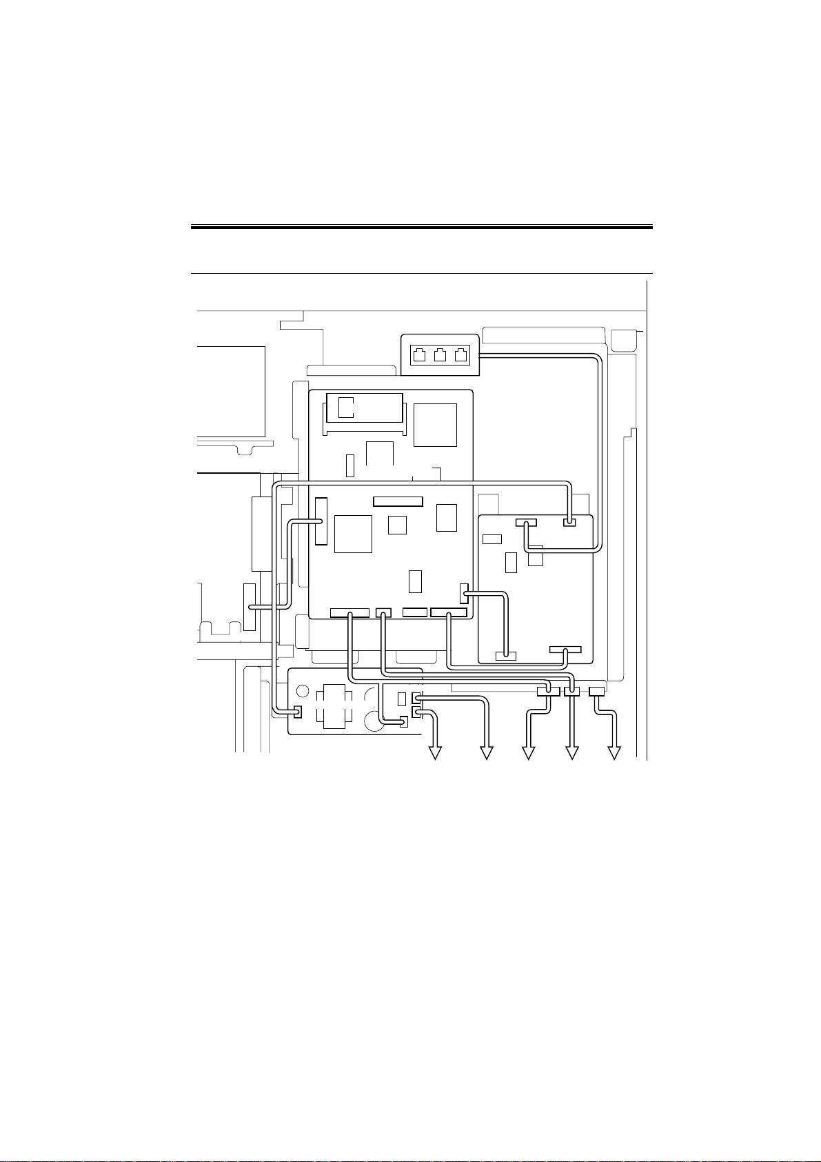
1.3 Points to Note When Accessing the DC Controller PCB
If you have to access the DC controller PCB, as for replacing the DIMM, you will have to
remove the G3 FAX Board [1]. To facilitate the wor k, detach the connector cover [2] shown
in the figure, and disconnect the connector found on the G3 fax control PCB before detaching the G3 FAX Boar d. (This way, you will have to remove fewer screws as compared with
disconnecting the connector on the controller side.)
COPYRIGHT
©
[2]
F03-103-01
2001 CANON INC. 2000 2000 2000 2000 CANON SUPER G3FAX BOARD-J1 REV.0 JUNE 2001
[1]
3-1

CHAPTER 3 TROUBLESHOOTING
1.4 Backing Up the Address Book
The data for an address book is stored on the host’s hard disk, and may be backed up using the remote user interface. If the user’s environment allows the use of a remote user interface, advise the user to back up the data as often as possible. The presence of a backup will
make restoration as in response to a fault on the hard disk easy.
Remote UI
Additional Functions>Custom Settings>Fax Settings>Import/Export
3-2
COPYRIGHT
F03-104-01
©
2001 CANON INC. 2000 2000 2000 2000 CANON SUPER G3 FAX BOARD-J1 REV.0 JUNE 2001

CHAPTER 3 TROUBLESHOOTING
2 Problems at Time of Installation
The G3 FAX board is not recognized.
Cause: The main controller will automatically identify the presence of a G3 fax
control PCB by communication with it at time of power-on. The cable
used for the communication may not be connected.
Remedy: Check to see if the cable between the main controller PCB and the G3
fax control PCB is correctly connected. (J1005 on the main controller
PCB, J31 on the G3 fax control PCB)
E674-0001 Error
Cause: E674-0001 is indicated when the MPU of the G3 FAX control PCB
does not respond although the main controller PCB and the G3 fax con
troller PCB are electrically connected. It also occurs when the G3 FAX
control PCB is not supplied with power and, as a result, the MPU of the
G3 fax board is not operating.
Remedy: Check to see if the cable between the main controller PCB and the G3
fax control PCB is correctly connected. (J1005 on the main controller
PCB, J31 on the G3 fax control PCB)
Remedy: Check to see if the G3 FAX Board DIMM is correctly installed. Or, the
program in the DIMM may be out of order. Replace the DIMM with a
normal one.
Remedy: Check to find out if the power line to the G3 FAX Board is correctly
connected. (J104 on the G3 fax control PCB and J124 on the
low-voltage power supply PCB)
COPYRIGHT
©
2001 CANON INC. 2000 2000 2000 2000 CANON SUPER G3FAX BOARD-J1 REV.0 JUNE 2001
3-3

CHAPTER 3 TROUBLESHOOTING
3 Common Problems
Communications fail.
Cause: The telephone line is not connected to the line modular jack.
Remedy: Connect the telephone line to the line modular jack (middle terminal).
Calling fails.
Cause: The wrong type of line (tone dial) is selected.
Remedy: Select the correct line type.
No sound is generated by the speaker.
Cause: The speaker is not correctly connected.
Remedy: Check the wiring from the G3 fax control PCB to the speaker. (J105 of
the G3 fax control PCB to the host relay cable; relay cable between
speaker behind the support cover and the copier)
The DONE stamp fails to operate.
Cause: the stamp has run out of ink.
Remedy: Replace the stamp cartridge.
3-4
COPYRIGHT
©
2001 CANON INC. 2000 2000 2000 2000 CANON SUPER G3 FAX BOARD-J1 REV.0 JUNE 2001
CHAPTER 3 TROUBLESHOOTING
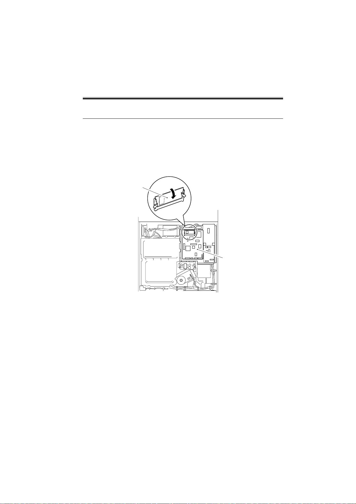
4 Upgrading
The firmware of the Board may be upgraded by either of the following two ways:
1. By replacing the DIMM ROM.
2. By upgrading the firmware contained by the DIMM ROM using a Service Support Tool.
For method 1 above, upgrading is done by mere replacement of the DIMM ROM shown
in the following diagram:
[1]
[2]
[1] DIMM ROM
[2] G3 fax control PCB
COPYRIGHT
©
2001 CANON INC. 2000 2000 2000 2000 CANON SUPER G3FAX BOARD-J1 REV.0 JUNE 2001
F03-400-01
3-5
 Loading...