

Canon Super G3 FAX Board-AP1, Super G3 FAX Board-AH1 Service Manual
654321
Super G3 FAX Board-AP1
Service Manual Rev 1

Application
This manual has been issued by Canon Inc. for qualied persons to learn technical theory,
installation, maintenance, and repair of products. This manual covers all localities where the
products are sold. For this reason, there may be information in this manual that does not
apply to your locality.
Corrections
This manual may contain technical inaccuracies or typographical errors due to improvements
or changes in products. When changes occur in applicable products or in the contents of this
manual, Canon will release technical information as the need arises. In the event of major
changes in the contents of this manual over a long or short period, Canon will issue a new
edition of this manual.
The following paragraph does not apply to any countries where such provisions are
inconsistent with local law.
Trademarks
The product names and company names used in this manual are the registered trademarks
of the individual companies.
Copyright
This manual is copyrighted with all rights reserved. Under the copyright laws, this manual may
not be copied, reproduced or translated into another language, in whole or in part, without the
consent of Canon Inc.
© CANON INC. 2013
Caution
Use of this manual should be strictly supervised to avoid disclosure of condential
information.
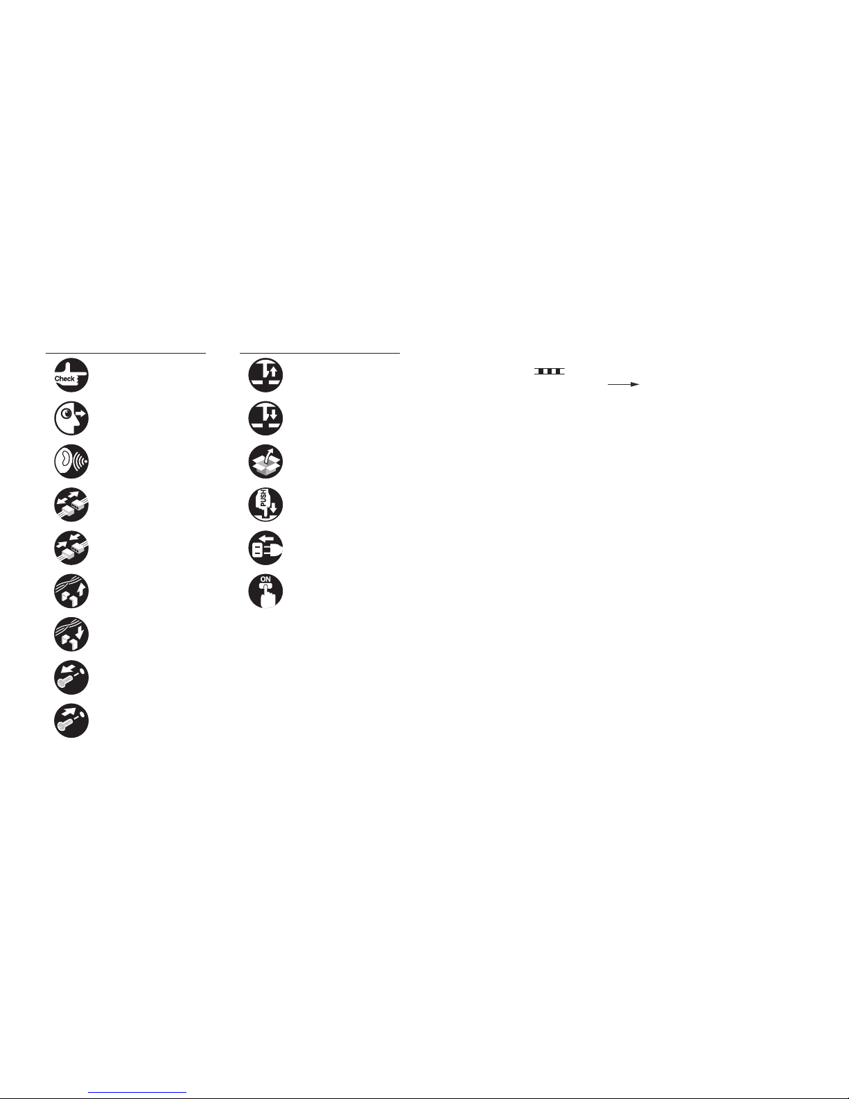
Explanation of Symbols
The following symbols are used throughout this Service Manual.
Symbols Explanation Symbols Explanation
Check. Remove the claw.
Check visually. Insert the claw.
Check the noise. Use the bundled part.
Disconnect the connector. Push the part.
Connect the connector. Plug the power cable.
Remove the cable/wire
from the cable guide or wire
saddle.
Turn on the power.
Set the cable/wire to the
cable guide or wire saddle.
Remove the screw.
Tighten the screw.
The following rules apply throughout this Service Manual:
1. Each chapter contains sections explaining the purpose of specic functions and the
relationship between electrical and mechanical systems with reference to the timing of
operation.
In the diagrams,
represents the path of mechanical drive; where a signal name
accompanies the symbol, the arrow
indicates the direction of the electric
signal.
The expression "turn on the power" means ipping on the power switch, closing the
front door, and closing the delivery unit door, which results in supplying the machine with
power.
2. In the digital circuits, '1' is used to indicate that the voltage level of a given signal is
"High", while '0' is used to indicate "Low". (The voltage value, however, differs from
circuit to circuit.) In addition, the asterisk (*) as in "DRMD*" indicates that the DRMD
signal goes on when '0'.
In practically all cases, the internal mechanisms of a microprocessor cannot be checked
in the eld. Therefore, the operations of the microprocessors used in the machines
are not discussed: they are explained in terms of from sensors to the input of the DC
controller PCB and from the output of the DC controller PCB to the loads.
The descriptions in this Service Manual are subject to change without notice for product
improvement or other purposes, and major changes will be communicated in the form of
Service Information bulletins.
All service persons are expected to have a good understanding of the contents of this Service
Manual and all relevant Service Information bulletins and be able to identify and isolate faults
in the machine.

1 Product Outline
Specications ------------------------------------------------------------------1-2
2 Technology
Basic Construction ------------------------------------------------------------2-2
Overview ----------------------------------------------------------------------------- 2-2
Controls --------------------------------------------------------------------------2-3
FAX communication control ----------------------------------------------------- 2-3
3 Parts Replacing and Cleaning
Parts List ------------------------------------------------------------------------3-2
PCBs ---------------------------------------------------------------------------------- 3-2
Parts Replacing and Cleaning ---------------------------------------------3-3
PCBs ---------------------------------------------------------------------------------- 3-3
4 Error Code
Overview ------------------------------------------------------------------------4-2
Guide to Error Code --------------------------------------------------------------- 4-2
User Error Code ---------------------------------------------------------------4-3
Service Error Code -----------------------------------------------------------4-6
Contents
5 Service Mode
Outline ---------------------------------------------------------------------------5-2
Service Mode Composition ------------------------------------------------------ 5-2
Using Service Mode --------------------------------------------------------------- 5-2
Menu Items -------------------------------------------------------------------------- 5-4
Setting of Bit Switch (SSSW) ----------------------------------------------5-5
Bit Switch Composition ----------------------------------------------------------- 5-5
Setting of Menu Switch (MENU) ---------------------------------------- 5-14
Menu Switch Composition ------------------------------------------------------ 5-14
Setting of Numeric Parameter (NUMERIC Param.) ---------------- 5-15
Numerical Parameter Composition -------------------------------------------5-15
Setting of Destination (TYPE) --------------------------------------------5-16
Overview ----------------------------------------------------------------------------5-16
Setting of Printer Functions (PRINTER) -------------------------------5-17
Setting of Bit Switch (SSSW) --------------------------------------------------5-17
Setting of Numeric Parameter (NUMERIC Param.) ----------------------5-18
IPFAX Setting ---------------------------------------------------------------- 5-18
IPFAX -------------------------------------------------------------------------------- 5-18
Initialization of Set Value (CLEAR) ------------------------------------- 5-19
Overview ----------------------------------------------------------------------------5-19
Test Mode (TEST) ---------------------------------------------------------- 5-19
Outline -------------------------------------------------------------------------------5-19
MODEM Test -----------------------------------------------------------------------5-20
Function Test -----------------------------------------------------------------------5-23
Service Report (REPORT) ------------------------------------------------5-24
System Data List ------------------------------------------------------------------ 5-24
System Dump List ----------------------------------------------------------------5-24
Error Transmission Report ------------------------------------------------------5-26
DCM ---------------------------------------------------------------------------- 5-27
Service modes related to fax of DCM ---------------------------------------- 5-27

6 Installation
How to Check This Installation Procedure ------------------------------ 6-2
When Using the Parts Included in the Package---------------------------- 6-2
Symbols in the Illustration ------------------------------------------------------- 6-2
Product Name ------------------------------------------------------------------6-2
Check Items When Turning OFF the Main Power --------------------6-2
Installation Outline Drawing ------------------------------------------------6-2
Points to Note When Installing ---------------------------------------------6-2
Checking the Contents ------------------------------------------------------6-3
Installation Procedure --------------------------------------------------------6-4
Operation Setting -------------------------------------------------------------6-8

1
1
Product OutlineProduct Outline
Product Outline
■Specications
1
1
Product Outline
Product Outline
1-2
1-2
Product Outline > Specications
Product Outline > Specications
Specications
Following is a specication list.
Item Description
Communication G3
Line type Subscriber line (PSTN)
Modulation <G3 image signal>
ITU-T V.27ter (2.4 Kbps, 4.8 Kbps)
ITU-T V.29 (7.2 Kbps, 9.6 Kbps)
ITU-T V.17 (TC 7.2 Kbps, TC 9.6 Kbps, 12 Kbps, 14.4 Kbps)
ITU-T V.34 (2.4 Kbps, 4.8 Kbps, 7.2 Kbps, 9.6 Kbps, 12 Kbps,
14.4 Kbps, 16.8 Kbps, 19.2 Kbps, 21.6 Kbps, 24 Kbps, 26.4
Kbps, 28.8 Kbps, 31.2 Kbps, 33.6 Kbps)
<G3 procedure signal>
ITU-T V.21 No.2 (300 bps)
ITU-T V.8, V.34 (300 bps)
Transmission speed 33.6 Kbps, 31.2 Kbps, 28.8 Kbps, 23.4 Kbps, 24 Kbps, 21.6
Kbps, 19.2 Kbps, 16.8 Kbps, 14.4 Kbps, 12 Kbps, TC 9.6
Kbps, TC 7.2 Kbps, 9.6 Kbps, 7.2 Kbps, 4.8 Kbps, 2.4 Kbps
auto fallback function
Coding method JBIG, MMR, MR, MH
G3-specic abridged procedure no
Modem IC conexant SFX336
Error correction ITU-T ECM
Transmission original size A3, A4, A4R, A5, A5R, B4, B5, B5R, LTR, LTRR, LGL, 11x17,
STMT, STMTR
ADF: double-sided originals accepted
Scanning line density Standard (200 x 100 dpi): 8 dots/mm x 3.85 lines/mm
Fine (200 x 200 dpi):8 dots/mm x 7.7 lines/mm
Super Fine (200 x 400 dpi): 8 dots/mm x 15.4 lines/mm
Ultra Fine (400 x 400 dpi): 16 dots/mm x 15.4 lines/mm
Halftone 256 gradations
Recording unit maximum reception size: A3 (297 mm x 420 mm)
scanning line density: 600 dpi x 600 dpi
Memory image memory (Canon Fax Standard Chart No.1):
HDD Model: 20000 prints
memory type:
Hard disk
storage: JBIG
Extension telephone connection no
Answering machine connection no
Fax/Tel switch-over no
Quick Direct Transmission yes
Transmission Header
(Add Remote Name on Header SW)
yes
Item Description
Remote reception no
Polling (F code) no
Memory box yes
Password reception yes
Machine telephone No. transmission yes
User abbreviation transmission yes
Dual access 64 (maximum number of reservations)
Broadcasting 256 targets (maximum number of targets)
maximum number of targets by 10 key dialing: 64 target
T-1-1

2
2
TechnologyTechnology
Technology
■Basic Construction
■Controls
2
2
Technology
Technology
2-2
2-2
Technology > Basic Construction > Overview
Technology > Basic Construction > Overview
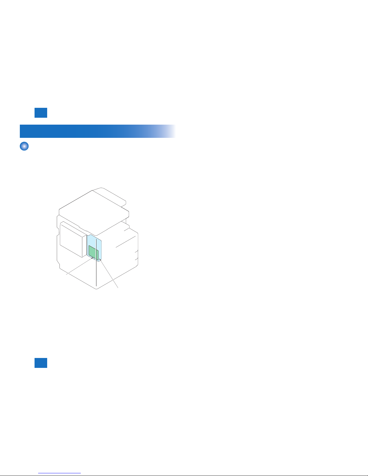
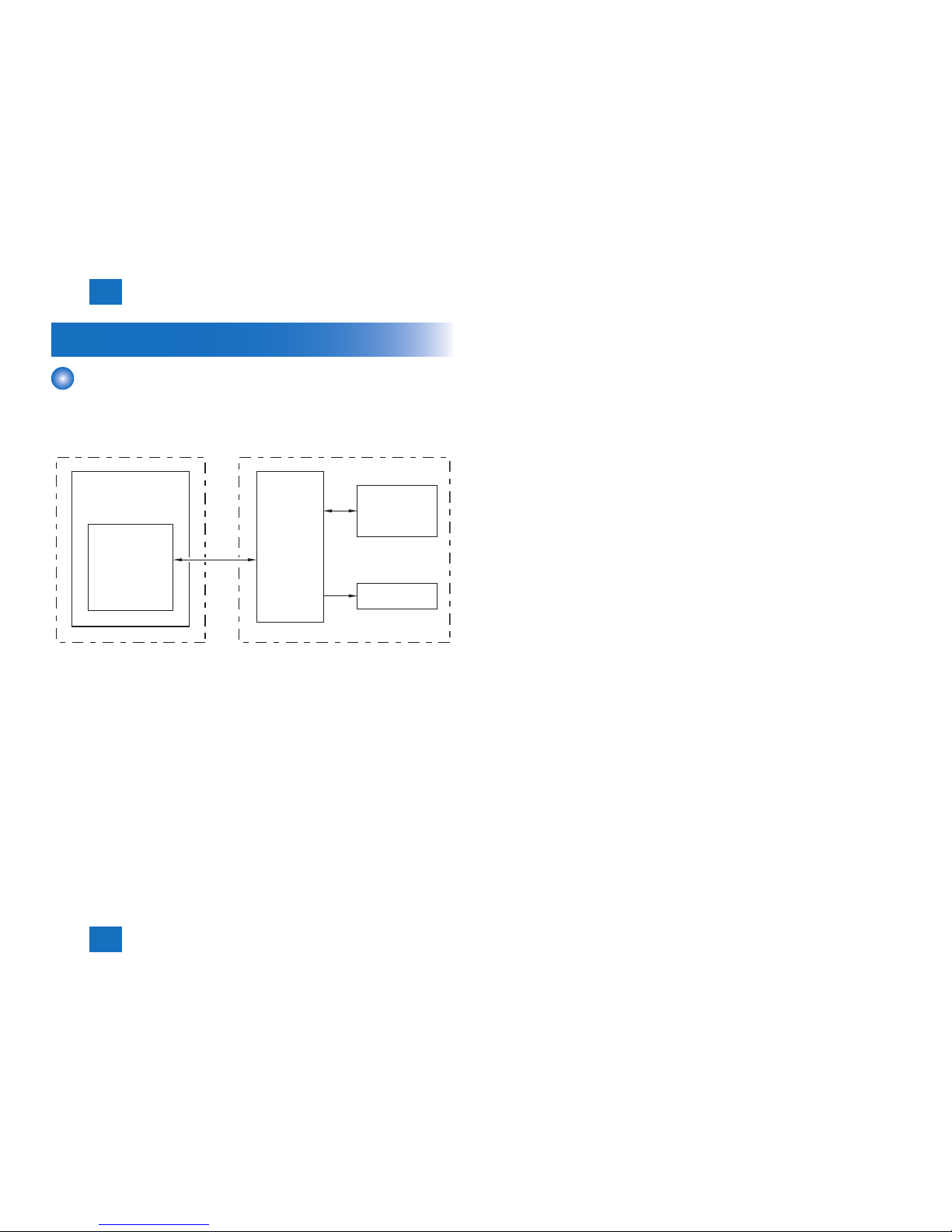
Basic Construction
Overview
This product is a FAX unit for adding FAX lines to the machine.
This machine is equipped with a telephone-based communication function and an image
processing function to enable a digital copier to serve as a highly functional multi-function fax
machine.
As for image transmission speed, it is capable of communicating at 33.6 kbps (max.) thanks
to a modem for V.34, which comply with ITU-T standard.
[1]
[2]
[1] Super G3 FAX Board-AP1
[2] G3 FAX PCB
F-2-1
2
2
Technology
Technology
2-3
2-3
Technology > Controls > FAX communication control
Technology > Controls > FAX communication control
Controls
FAX communication control
The main controller in the machine executes FAX communication control.
The FAX control program is loaded on the main controller and controls the G3 FAX PCB in
the FAX unit.
FAX interface G3 FAX PCB
Main controller 1
Modular PCB
FAX unit for one lineCopier
Speaker
F-2-2

3
3
Parts Replacing and CleaningParts Replacing and Cleaning
Parts Replacing and Cleaning
■Parts List
■Parts Replacing and Cleaning

3
3
Parts Replacing and Cleaning
Parts Replacing and Cleaning
3-2
3-2
Parts Replacing and Cleaning > Parts List > PCBs
Parts Replacing and Cleaning > Parts List > PCBs
Parts List
PCBs
No. Part name Reference
[1] G3 FAX PCB [2] Modular PCB -
[2]
[1]
T-3-1
F-3-1
3
3
Parts Replacing and Cleaning
Parts Replacing and Cleaning
3-3
3-3
Parts Replacing and Cleaning > Parts Replacing and Cleaning > PCBs > G3 Fax Unit
Parts Replacing and Cleaning > Parts Replacing and Cleaning > PCBs > G3 Fax Unit
Parts Replacing and Cleaning
PCBs
■G3 Fax Unit
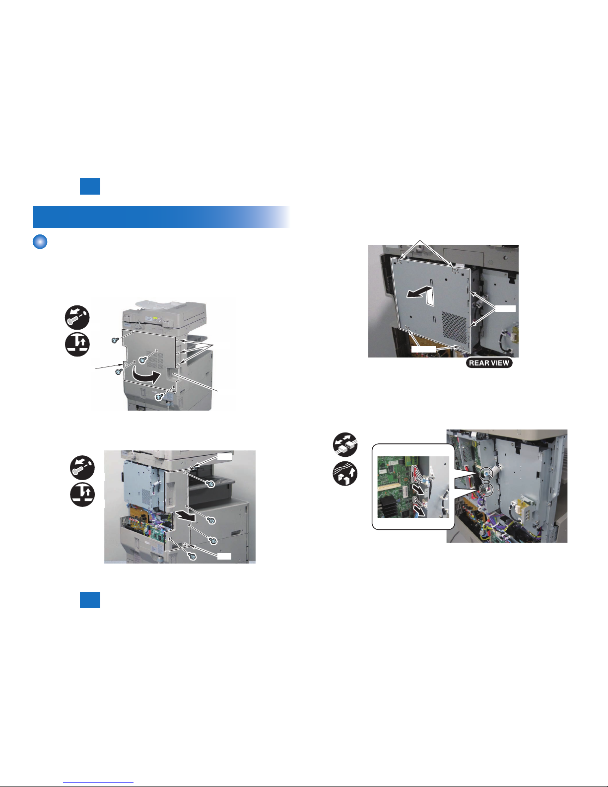
1) Remove the Rear Cover.
• 4 Screws
• 4 Claws
x4
x4
Claw
Rear Cover
Claw
2) Remove the Left Rear Cover.
• 4 Screws
• 2 Claws
x4
x2
Claw
Claw
F-3-2
F-3-3
3) Remove the Controller Box Cover.
• 6
Hooks
Hook
Hook
Hook
4) Release the 2 harnesses of the Fax Unit in place, and release the harnesses from the
Controller PCB.
• 2 Connectors
• 2 Edge Saddles
x2
x2
F-3-4
F-3-5
3
3
Parts Replacing and Cleaning
Parts Replacing and Cleaning
3-4
3-4
Parts Replacing and Cleaning > Parts Replacing and Cleaning > PCBs > G3 Fax Unit
Parts Replacing and Cleaning > Parts Replacing and Cleaning > PCBs > G3 Fax Unit
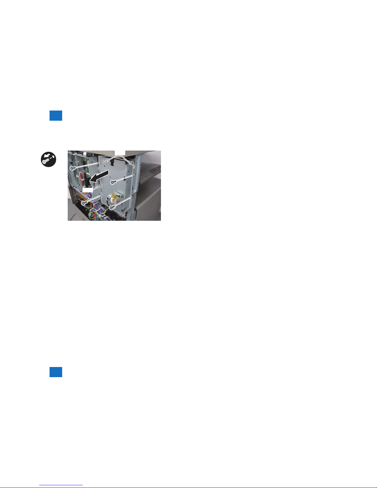
5) Remove the G3 Fax Unit.
• 4 Screws
• 3
Hooks
Hook
Hook
x4
F-3-6

4
4
Error CodeError Code
Error Code
■Overview
■User Error Code
■Service Error Code

4
4
Error Code
Error Code
4-2
4-2
Error Code > Overview > Guide to Error Code
Error Code > Overview > Guide to Error Code
Overview
Guide to Error Code
When the Board has been installed and '1' is set for service data #1 SSSW SW01 bit 0,
communications ending in error will be indicated in the following reports using service error
codes: communications management report, reception result report, and error transmission
report.
You can also check the code of an error by making the following selections: System Monitor >
Fax > Detail.
The major error codes used by the Board are listed on the pages that follow. For information
on causes and remedies in connection with other error codes, see the "G3/G4 Facsimile Error
Code List" (HY8-23A0-020).
If the Board indicates a service error code, try the following:
- Increase the transmission level.
Set -8 (dBm) for service data #2 MENU parameter No. 007.
- Decrease the transmission level.
Set -15 (dBm) to service data #2 MENU parameter No. 007.
- Provide a remedy against echoes.
Change the following bit setting for service data #1 SSSW SW03:
Bit4 -> 1: to cause the machine to ignore the rst DIS signal from the other party.
-> 0: to cause the machine to ignore the rst DIS signal from the other party.
Bit5 -> 1: to cause the machine to transmit a tonal signal (1850 or 1650 Hz) in response to
the DIS signal from the other party.
-> 0: to cause the machine not to send a total signal (1850 or 1650 Hz) in response to
the DIS signal from the other party.
Bit6 -> 1: to cause the machine to send a 1850-Hz tonal signal if bit 5 is set to '1'.
-> 0: to cause the machine to send a 1650-Hz tonal signal if bit 5 is set to '1'.
Bit7 -> 1: to cause the machine to send a total signal before sending the CED signal.
-> 0: to causes the machine not to send a tonal signal before sending the CED signal.
- EPT (echo protect tone)
Change the setting of service data #1 SSSW SW03 bit 1:
Bit1 -> 1: to cause the machine to send EPT.
-> 0: to cause the machine not to send EPT.
- Adjust the NL equalizer.
Set '1' for serve data #2 MENU parameter No. 005.
- Decrease the transmission start speed.
Decrease the transmission start speed in user mode: System Settings > Communications
Settings > Fax Settings > Send Start Speed.
- Make the TCF evaluation standards lenient.
The Board does not offer a means by which to provide this remedy.
- Make the RTN transmissions conditions lenient.
Change parameters No. 2 through No. 004 of service data #3 NUMERIC Param.
No. 002: error rate for all lines; change it so that it is closer to 99%.
No. 003: number of lines in connection with bursts; change it so that it is closer to 99 lines.
No. 004: number of errors falling short of a specic number of lines in connection with
bursts; change it so that it is closer to 99.
- Increase the length of silence after reception of CFR.
Set '1' for service data #1 SSSW SW04 bit 4.
Bit4 -> 1: length of time during which a low-speed signal is ignored after transmission of
CFR; 1500 msec
-> 0: length of time during which a low-speed signal is ignored after transmission of
CFR; 700 msec
- <When using IPFAX> Change the mode of T.38 to "TCP".
Change "SIP TX Transport" to "TCP" in [Media (T.38) Settings].
4
4
Error Code
Error Code
4-3
4-3
Error Code > User Error Code
Error Code > User Error Code
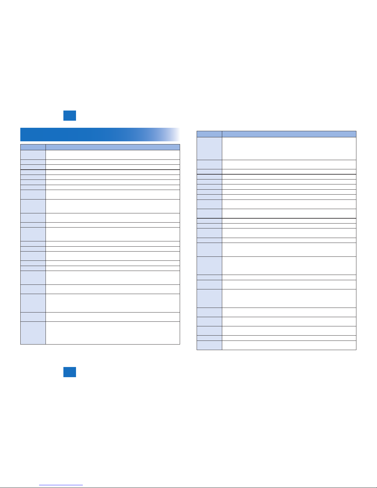
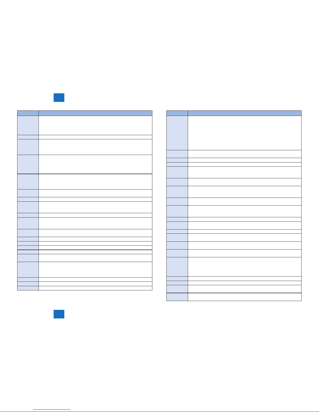
User Error Code
No. Description
#001
Different sized originals were scanned without setting the Different Size Originals
mode.
#003
Time-out for copying or sending/receiving a single page has occurred.
#005
Time-out for initial identication (T0/T1) has occurred.
#009
Recording paper has jammed or is absent.
#011
The document that you are sending is not placed correctly.
#012
Recording paper is absent at the other party.
#018
Auto call initiation has failed.
#019
Sending could not be performed because the memory of the Remote Fax server
machine became full when sending a fax from the Remote Fax client machine
#022
Documents could not be forwarded to the specied destination because there is
insufcient memory available. The machine can store up to total of 71 jobs of
send and transmission report in memory.
#025
A telephone line not connected to the Remote Fax server machine was specied
when sending fax from the Remote Fax client machine.
#037
Image memory overow at time of reception has occurred.
#040
Sending could not be performed because there was insufcient memory available
in the Remote Fax server machine when sending a fax from the Remote Fax client
machine.
#080
A subaddress is not set in the recipient's machine.
#081
A password is not set in the recipient's machine.
#099
A job was canceled during transmission to a USB memory media device.
A secured print job was automatically canceled after the timeout period elapsed.
#102
The subaddress and/or password do not match.
#107
The document could not be sent because there was insufcient memory available.
#401
The USB memory media device is full or the maximum number of les that can be
stored in the root directory (the top level of the directory tree in the USB memory
media device) has been reached.
#402
The image transfer failed when transferring to the memory media because an
invalid character (such as \) was included in the specied lename.
#403
The job failed because a le with the same name already exists. Generally, if a le
with the same name exists, a number ranging from 1 to 999 is added to the tail of
the name to prevent naming conicts. However, this error occurred because a le
with the same number added to its le name already exists.
#404
The job failed because the write protect switch of the USB memory media device
was on.
#406
The job failed because the USB memory media device was pulled out during
transmission.
An error occurred while data, such as image data, was being transferred to the USB
memory media device. (The connected device may be formatted with a le system
that is not supported by the machine.)
No. Description
#407
The length of the full path to the specied le (or folder) exceeded the supported
limit.
The transmission to the USB memory media device was not properly performed
because the length of the full path including the root and le name exceeded the
limit.
#409
The le could not be saved because the maximum number of les that can be
saved in the destination has been reached.
#410
Storing cannot be performed because there are too many jobs waiting to be stored.
#411
The les are already locked by the other operations.
#701
The specied Department ID does not exist, or the password has changed.
#702
The document could not be sent because the memory is full.
#703
The memory for image data is full when sending color documents.
#704
An error occurred when reading address information from the Address Book.
#705
The send operation was interrupted because the size of the image data is larger
than the maximum data size sets in [Maximum Data Size for Sending].
#706
The address book is currently being imported/exported from the Remote UI, or the
machine is busy with other send related functions.
#711
The Fax/I-Fax Inbox memory is full.
#712
The maximum number of les is already stored in the Fax/I-Fax Inbox.
#713
The document in Fax/I-Fax Inbox was deleted before the link to it was sent via
e-mail.
#749
You could not execute the job because a service call message is being displayed.
#751
The le server is not functioning.
The network is down (the server is unable to connect to the network or was
disconnected).
#752
The SMTP server name and e-mail address are incorrect.
The domain name is incorrect.
The SMTP server is not functioning.
The network is down.
#753
A TCP/IP error occurred while sending an e-mail. (Socket, Select error, etc.)
#754
The client machine is not functioning or the network is down when device
information is being delivered. The destination setting is incorrect.
#755
Jobs cannot be sent because TCP/IP is not functioning correctly.
The IP address is not set.
When the machine was turned ON, an IP address was not assigned to the machine
by the DHCP, RARP, or BOOTP server.
#759
An error occurred on while sending a link via e-mail to the Mail Box in which the le
is stored.
#761
A PDF or XPS le with a digital signature could not be sent, because a digital
certicate or key pair registered in the machine is corrupt or could not be accessed.
#762
Could not send to a domain that is not registered as an allowed domain, because
[Allow MDN Not via Server] is set to 'On'.
#766
The certicate used to send a PDF or XPS with a digital signature has expired.
#770
Data could not be sent with WebDAV, because the WebDAV server or proxy server
does not support SSL communications.
4
4
Error Code
Error Code
4-4
4-4
Error Code > User Error Code
Error Code > User Error Code
No. Description
#771
The setting for the Remote Fax Server Address is incorrect.
The Remote Fax Server has not been started.
The network is not connected.
The Remote Fax server could not be connected to because the machine could not
connect to the DNS server.
#772
The URL for the Rights Management Server is incorrect.
#773
[The following user mode] is set to 'On', and PDF modes that cannot be set are
selected in forwarding settings.
[Settings/Registration]>[Function Settings] → [Common] → [Generate File].
>[Optimize PDF for Web]>[On] → [OK]
#801
A timeout error occurred while the machine was communicating with the SMTP
server to send an e-mail or send/receive an I-fax.
The SMTP server returned an error while trying to connect. The destination is
not correct.
An error occurred on the server side during transmission to a le server.
#802
The name of the SMTP server is incorrect.
The DNS server address settings are incorrect.
The domain name is incorrect.
Connection to the DNS server failed.
#803
The connection was interrupted due to reasons on the recipient's side before all of
the pages could be sent.
#804
You do not have permission to access the folder.
#806
An incorrect user name or password was specied for the sending of a le to a le
server.
An incorrect destination was specied for the sending of an e-mail message or I-fax.
#807
You do not have access privileges for the specied directory.
#810
A POP server connection error occurred while receiving an I-fax.
The POP server returned an error during the connection.
A timeout error occurred on the server while connecting to the POP server.
#815
You cannot log on to the le server because the machine is printing a document
sent to that server. Simultaneous connections are not possible.
#816
You have reached the quota for the number of pages you can scan.
#817
A communication error occurred between your machine and a cascade copy printer.
#818
The received data is not in a printable le format.
#819
You have received data that cannot be processed (MIME information is incorrect).
#820
You have received data that cannot be processed (BASE 64 or uuencode is
incorrect).
#821
You have received data that cannot be processed (TIFF analysis error).
When you are using the Media Print function, printing cannot be performed
because you have selected a JPEG or TIFF le with unsupported le formats or a
corrupted image le.
#822
You have received data that cannot be processed (image data cannot be decoded).
#823
Unable to connect to a cascade copy printer.
#824
A communication error occurred in a cascade copy printer.
No. Description
#825
The Department ID and password set on the host machine do not match those
registered in the cascade copy printers.
Printing could not be performed because the Department ID and PIN for a reserved
or executing printing job were deleted, or the PIN was changed.
Device information could not be delivered because the System Manager is
registered on the destination client machine but not on the host machine.
Or device information could not be delivered because the System Manager ID and
System PIN registered in the client machine differs from the System Manager ID
and System PIN registered in the host machine.
#827
You have received data that cannot be processed (contains MIME information that
is not supported).
#828
You have received HTML data.
#829
Data consisting of more than approximately 1,000 pages is received.
#830
A DSN (Delivery Status Notication) error notication was received because of an
incorrect I-fax address or destination setting, or because the data size of the sent
documents exceeds the mail server capacity.
#831
An I-fax document could not be received using SMTP because of the Receive Filter
setting in Firewall Settings.
#832
DSN (Delivery Status Notication) mail was not sent because TCP/IP Settings in
Network or Communication Settings in E-Mail/I-Fax Settings have not been set.
Alternatively, DSN mail was not sent due to a problem with the mail server.
#833
MDN (Mail Delivery Notication) mail was not sent because TCP/IP Settings have
not been set, or due to a problem with the mail server.
#834
An MDN (Mail Delivery Notication) error notication was received because of an
incorrect I-fax address or destination setting, or because trouble occurred in the
network or mail server. Alternatively, the memory of the receiving machine is full.
#835
The maximum number of text lines for receiving an I-fax has been exceeded.
#837
A connection request was received from a host whose connection is restricted by
the Receive Filter settings in Firewall Settings.
#839
The user name or password for the SMTP Authentication is incorrect.
#841
An encryption algorithm that matches the mail server does not exist for sending
e-mail or I-fax.
#842
The mail server requested authentication using the client certicate for sending an
e-mail or I-fax.
#843
There is a large difference between the current time set in the KDC (Key Distribution
Center) server and the time set in the machine.
#844
When sending with POP before SMTP, SSL encrypted communication with the POP
server failed.
Verication of the SSL server certicate was attempted when receiving with POP
because [Conrm SSL Certicate for POP RX] is set to 'On', but verication failed
and receiving could not be performed.
#845
When sending with POP before SMTP, POP authentication (POP AUTH) failed.
#846
When sending with POP before SMTP, POP authentication (APOP) failed.
#847
Could not save the received le in the Condential Fax Inbox, as the memory of the
Mail Box or Fax/I-Fax Inbox is full.
#849
Device information could not be delivered because the destination client machine is
executing a job.
 Loading...