

654321
Super G3 FAX Board-AD2
Service Manual Rev.0

Application
This manual has been issued by Canon Inc. for qualied persons to learn technical theory,
installation, maintenance, and repair of products. This manual covers all localities where the
products are sold. For this reason, there may be information in this manual that does not
apply to your locality.
Corrections
This manual may contain technical inaccuracies or typographical errors due to improvements
or changes in products. When changes occur in applicable products or in the contents of this
manual, Canon will release technical information as the need arises. In the event of major
changes in the contents of this manual over a long or short period, Canon will issue a new
edition of this manual.
The following paragraph does not apply to any countries where such provisions are
inconsistent with local law.
Trademarks
The product names and company names used in this manual are the registered trademarks
of the individual companies.
Copyright
This manual is copyrighted with all rights reserved. Under the copyright laws, this manual may
not be copied, reproduced or translated into another language, in whole or in part, without the
consent of Canon Inc.
© CANON INC. 2011
Caution
Use of this manual should be strictly supervised to avoid disclosure of condential
information.
Explanation of Symbols
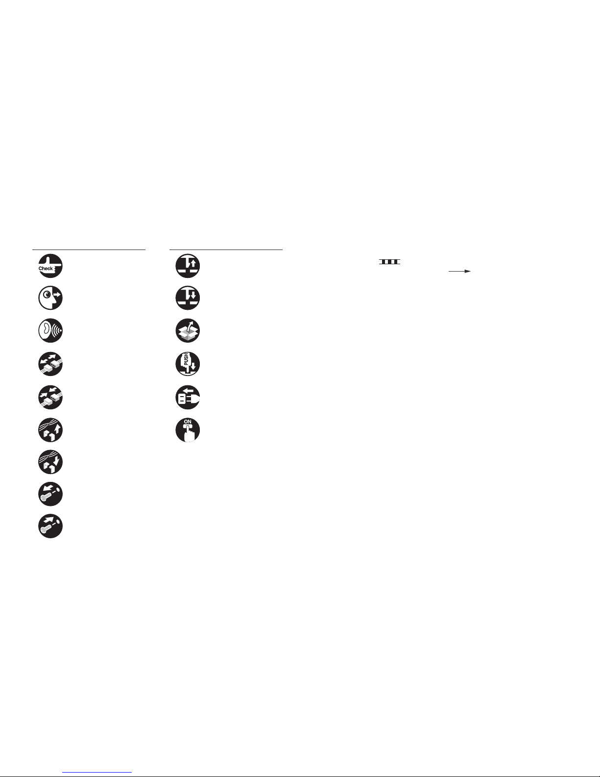
The following symbols are used throughout this Service Manual.
Symbols Explanation Symbols Explanation
Check. Remove the claw.
Check visually. Insert the claw.
Check the noise. Use the bundled part.
Disconnect the connector. Push the part.
Connect the connector. Plug the power cable.
Remove the cable/wire
from the cable guide or wire
saddle.
Turn on the power.
Set the cable/wire to the
cable guide or wire saddle.
Remove the screw.
Tighten the screw.
The following rules apply throughout this Service Manual:
1. Each chapter contains sections explaining the purpose of specic functions and the
relationship between electrical and mechanical systems with reference to the timing of
operation.
In the diagrams,
represents the path of mechanical drive; where a signal
name accompanies the symbol, the arrow
indicates the direction of the
electric signal.
The expression "turn on the power" means ipping on the power switch, closing the
front door, and closing the delivery unit door, which results in supplying the machine with
power.
2. In the digital circuits, '1' is used to indicate that the voltage level of a given signal is
"High", while '0' is used to indicate "Low". (The voltage value, however, differs from
circuit to circuit.) In addition, the asterisk (*) as in "DRMD*" indicates that the DRMD
signal goes on when '0'.
In practically all cases, the internal mechanisms of a microprocessor cannot be checked
in the eld. Therefore, the operations of the microprocessors used in the machines
are not discussed: they are explained in terms of from sensors to the input of the DC
controller PCB and from the output of the DC controller PCB to the loads.
The descriptions in this Service Manual are subject to change without notice for product
improvement or other purposes, and major changes will be communicated in the form of
Service Information bulletins.
All service persons are expected to have a good understanding of the contents of this Service
Manual and all relevant Service Information bulletins and be able to identify and isolate faults
in the machine.

Contents
0 Product Outline
Specications ------------------------------------------------------------------1-2
Basic Construction ------------------------------------------------------------1-3
Overview ----------------------------------------------------------------------------- 1-3
1 Technology
Basic Construction ------------------------------------------------------------2-2
Overview ----------------------------------------------------------------------------- 2-2
Controls --------------------------------------------------------------------------2-2
FAX communication control ----------------------------------------------------- 2-2
2 Parts Replacing and Cleaning
Parts List ------------------------------------------------------------------------3-2
PCBs ---------------------------------------------------------------------------------- 3-2
Parts Replacing ----------------------------------------------------------------3-3
Removing the Fax Unit ----------------------------------------------------------- 3-3
Procedure ------------------------------------------------------------------------------------- 3-3
Removing the Speaker Unit ----------------------------------------------------- 3-6
Procedure ------------------------------------------------------------------------------------- 3-6
3 Error Code
Overview ------------------------------------------------------------------------4-2
Guide to Error Code --------------------------------------------------------------- 4-2
User Error Code ---------------------------------------------------------------4-3
Service Error Code -----------------------------------------------------------4-3
4 Service Mode
Outline ---------------------------------------------------------------------------5-2
Outline of Service Mode ---------------------------------------------------------- 5-2
Using the Mode --------------------------------------------------------------------- 5-3
Setting of Bit Switch --------------------------------------------------------------- 5-3
Outline ----------------------------------------------------------------------------------------- 5-3
Back-Up ------------------------------------------------------------------------------ 5-4
Service Label ----------------------------------------------------------------------- 5-4
Details of Service Mode -----------------------------------------------------5-5
#SSSW ------------------------------------------------------------------------------- 5-5
SSSW Composition ------------------------------------------------------------------------ 5-5
Details ----------------------------------------------------------------------------------------- 5-5
#MENU ------------------------------------------------------------------------------5-15
Menu Switch Composition ---------------------------------------------------------------5-15
Details ----------------------------------------------------------------------------------------5-15
#NUMERIC ------------------------------------------------------------------------- 5-16
Numerical Parameter Composition----------------------------------------------------5-16
Details ----------------------------------------------------------------------------------------5-17
#SCAN -------------------------------------------------------------------------------5-22
Setting of Scanner Functions (SCANNER) -----------------------------------------5-22
SCAN SW -----------------------------------------------------------------------------------5-25
Numeric Parameter Settings (Numeric Prama.) -----------------------------------5-26
READER ------------------------------------------------------------------------------------- 5-27
FEEDER -------------------------------------------------------------------------------------5-31
#PRINT ------------------------------------------------------------------------------ 5-32
Numeric Parameter Settings (Numeric Prama) ------------------------------------5-32
Service Soft Switch Settings (PRINTER) --------------------------------------------5-33
List of Functions ----------------------------------------------------------------------------5-34
List of Functions(PRINT CST) ----------------------------------------------------------5-37
#NETWORK ------------------------------------------------------------------------5-38
Conguration --------------------------------------------------------------------------------5-38
Conrmation of contents of CA certicate -------------------------------------------5-39
#CODEC ----------------------------------------------------------------------------5-39
Conguration --------------------------------------------------------------------------------5-39
Details ----------------------------------------------------------------------------------------5-39
#SYSTEM ---------------------------------------------------------------------------5-40
Conguration --------------------------------------------------------------------------------5-40
Details of Bit Switch -----------------------------------------------------------------------5-40
Details of System Numeric --------------------------------------------------------------5-41
#ACC ---------------------------------------------------------------------------------5-42
Conguration --------------------------------------------------------------------------------5-42
#COUNTER ------------------------------------------------------------------------5-42

Counters -------------------------------------------------------------------------------------5-42
Clearing Counters -------------------------------------------------------------------------5-43
#LMS ---------------------------------------------------------------------------------5-43
Conguration --------------------------------------------------------------------------------5-43
Outline ---------------------------------------------------------------------------------------- 5-44
Details ----------------------------------------------------------------------------------------5-44
Method of conrming license option --------------------------------------------------5-44
Inactivity of the transmitted license----------------------------------------------------5-44
Erasing a License--------------------------------------------------------------------------5-46
#E-RDS ------------------------------------------------------------------------------5-47
Conguration --------------------------------------------------------------------------------5-47
#REPORT ---------------------------------------------------------------------------5-47
Conguration -------------------------------------------------------------------------------- 5-47
Details ----------------------------------------------------------------------------------------5-48
#DOWNLOAD ---------------------------------------------------------------------5-52
Download ------------------------------------------------------------------------------------5-52
#CLEAR ----------------------------------------------------------------------------- 5-52
Conguration -------------------------------------------------------------------------------- 5-52
#DISPLAY ---------------------------------------------------------------------------5-53
Conguration -------------------------------------------------------------------------------- 5-53
#ROM -------------------------------------------------------------------------------- 5-53
Conguration -------------------------------------------------------------------------------- 5-53
#TEST MODE ---------------------------------------------------------------------5-53
Outline ---------------------------------------------------------------------------------------- 5-53
Conguration -------------------------------------------------------------------------------- 5-54
Details ----------------------------------------------------------------------------------------5-54
5 Installation
How to Check this Installation Procedure --------------------------------- 3
When Using the Parts Included in the Package------------------------------- 3
Symbols in the Illustration ---------------------------------------------------------- 3
Product Name -------------------------------------------------------------------- 3
Checking the Contents -------------------------------------------------------- 4
Check Items when Turning OFF the Main Power ----------------------- 4
Installation Outline Drawing -------------------------------------------------- 4
Installation Procedure ---------------------------------------------------------- 5
Installing the Fax Unit ---------------------------------------------------------------- 5
Installing the Speaker ---------------------------------------------------------------- 9
Operation Setting --------------------------------------------------------------12
Type Setting -------------------------------------------------------------------------- 12
Basic Setting ------------------------------------------------------------------------- 12
Fax Communication Test ---------------------------------------------------------- 13

1
1
Product OutlineProduct Outline
Product Outline
■Specications
1
1
Product Outline
Product Outline
1-2
1-2
Product Outline > Specications
Product Outline > Specications
Specications
Following is a specication list.
Item Description
Communication G3
Line type Subscriber line (PSTN)
Modulation <G3 image signal>
ITU-T V.27ter (2.4 Kbps, 4.8 Kbps)
ITU-T V.29 (7.2 Kbps, 9.6 Kbps)
ITU-T V.17 (TC 7.2 Kbps, TC 9.6 Kbps, 12 Kbps, 14.4 Kbps)
ITU-T V.34 (2.4 Kbps, 4.8 Kbps, 7.2 Kbps, 9.6 Kbps, 12 Kbps,
14.4 Kbps, 16.8 Kbps, 19.2 Kbps, 21.6 Kbps, 24 Kbps, 26.4
Kbps, 28.8 Kbps, 31.2 Kbps, 33.6 Kbps)
<G3 procedure signal>
ITU-T V.21 No.2 (300 bps)
ITU-T V.8, V.34 (300 bps)
Transmission speed 33.6 Kbps, 31.2 Kbps, 28.8 Kbps, 23.4 Kbps, 24 Kbps, 21.6
Kbps, 19.2 Kbps, 16.8 Kbps, 14.4 Kbps, 12 Kbps, TC 9.6
Kbps, TC 7.2 Kbps, 9.6 Kbps, 7.2 Kbps, 4.8 Kbps, 2.4 Kbps
auto fallback function
Coding method JBIG, MMR, MR, MH
G3-specic abridged procedure no
Modem IC conexant DFX336
Error correction ITU-T ECM
Transmission original size A4-R, A5-R, B5-R, LGL, LTR-R, STMT-R, EXEC-R, 16K
ADF: double-sided originals accepted
Scanning line density Standard (200 x 100 dpi): 8 dots/mm x 3.85 lines/mm
Fine (200 x 200 dpi):8 dots/mm x 7.7 lines/mm
Super Fine (200 x 400 dpi): 8 dots/mm x 15.4 lines/mm
Ultra Fine (400 x 400 dpi): 16 dots/mm x 15.4 lines/mm
Halftone 256 gradations
Recording unit maximum reception size: A4 (297 mm x 210 mm)
scanning line density: 600 dpi x 600 dpi
Memory image memory (Canon Fax Standard Chart No.1):
1000 prints
storage: JBIG
Extension telephone connection no
Answering machine connection no
Fax/Tel switch-over no
Quick Direct Transmission no
Transmission Header
(Add Remote Name on Header SW)
yes
Remote reception no
Polling (F code) no
Item Description
Memory box yes
Password reception no
Machine telephone No. transmission yes
User abbreviation transmission no
Dual access 64 (maximum number of reservations)
Broadcasting Maximum number of targets:
Address book: 500
New targets: 32
Maximum number of targets by 10 key dialing: 32
T-1-1
1
1
Product Outline
Product Outline
1-3
1-3
Product Outline > Basic Construction > Overview
Product Outline > Basic Construction > Overview
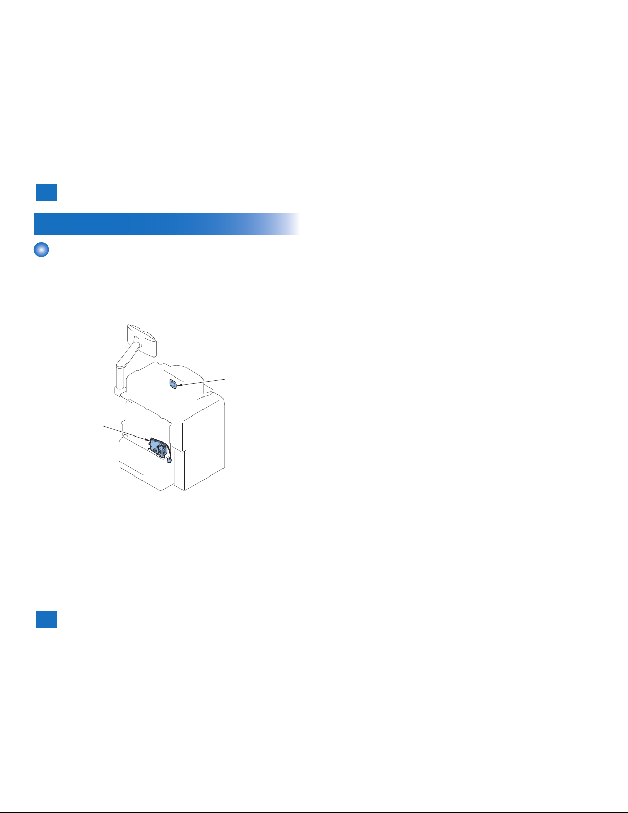
Basic Construction
Overview
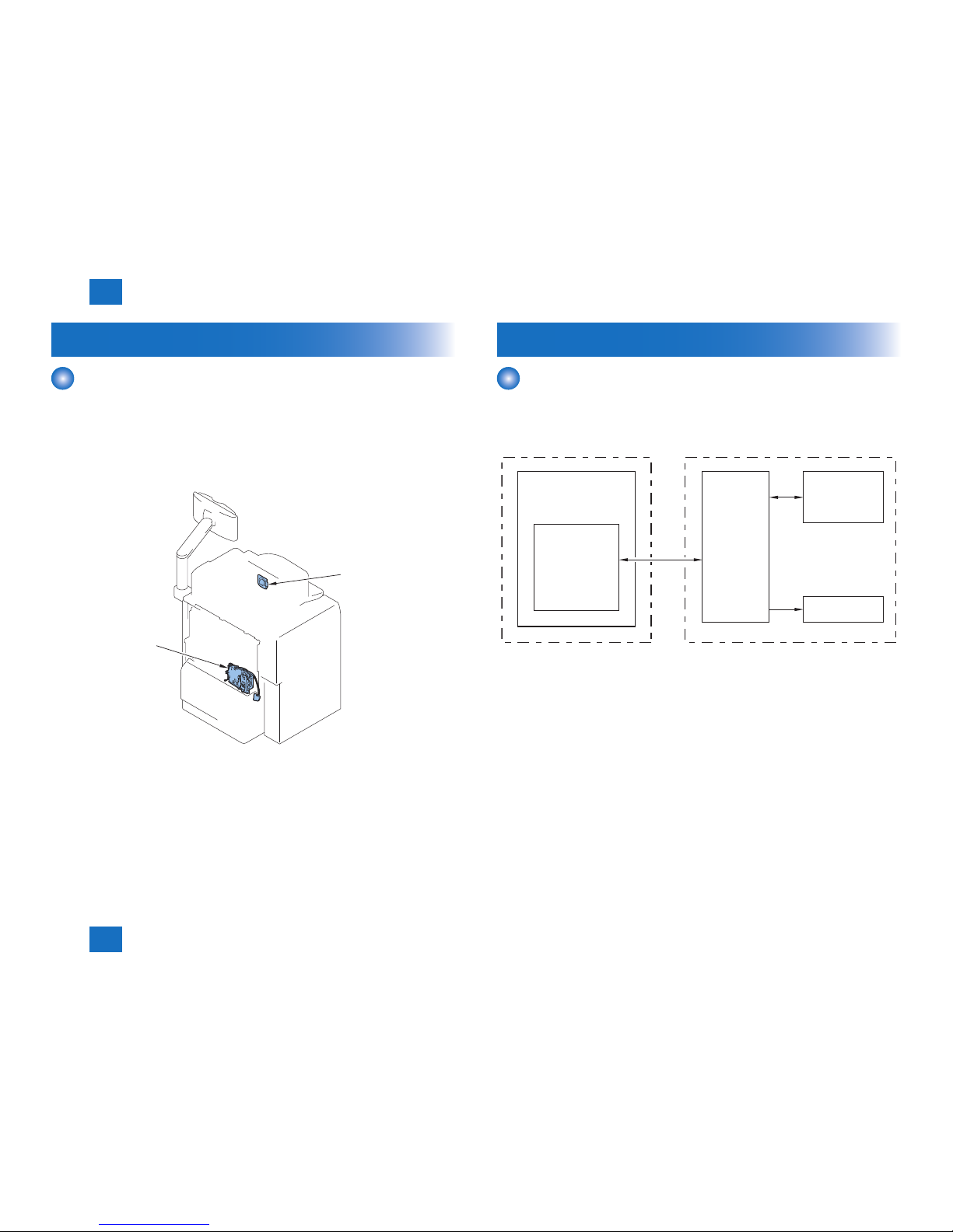
This product is a FAX unit for adding FAX lines to the machine.
This machine is equipped with a telephone-based communication function and an image
processing function to enable a digital copier to serve as a highly functional multi-function fax
machine.
As for image transmission speed, it is capable of communicating at 33.6 kbps (max.) thanks
to a modem for V.34, which comply with ITU-T standard.
[1]
[2]
[1] Super G3 FAX Board-AD2
[2] Speaker unit
F-1-1

2
2
TechnologyTechnology
Technology
■Basic Construction
■Controls
2
2
Technology
Technology
2-2
2-2
Technology > Controls > FAX communication control
Technology > Controls > FAX communication control
Basic Construction
Overview
This product is a FAX unit for adding FAX lines to the machine.
This machine is equipped with a telephone-based communication function and an image
processing function to enable a digital copier to serve as a highly functional multi-function fax
machine.
As for image transmission speed, it is capable of communicating at 33.6 kbps (max.) thanks
to a modem for V.34, which comply with ITU-T standard.
[1]
[2]
[1] Super G3 FAX Board-AD2
[2] Speaker unit
F-2-1
Controls
FAX communication control
The main controller in the machine executes FAX communication control.
The FAX control program is loaded on the main controller and controls the G3 FAX PCB in
the FAX unit.
FAX interface
G3 FAX PCB
Main controller
Modular PCB
FAX unitCopier
Speaker
F-2-2

3
3
Parts Replacing and CleaningParts Replacing and Cleaning
Parts Replacing and Cleaning
■Parts List
■Parts Replacing
3
3
Parts Replacing and Cleaning
Parts Replacing and Cleaning
3-2
3-2
Parts Replacing and Cleaning > Parts List > PCBs
Parts Replacing and Cleaning > Parts List > PCBs
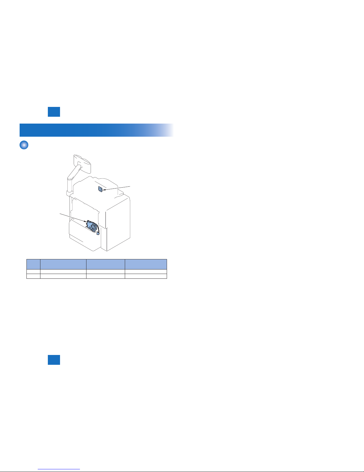
Parts List
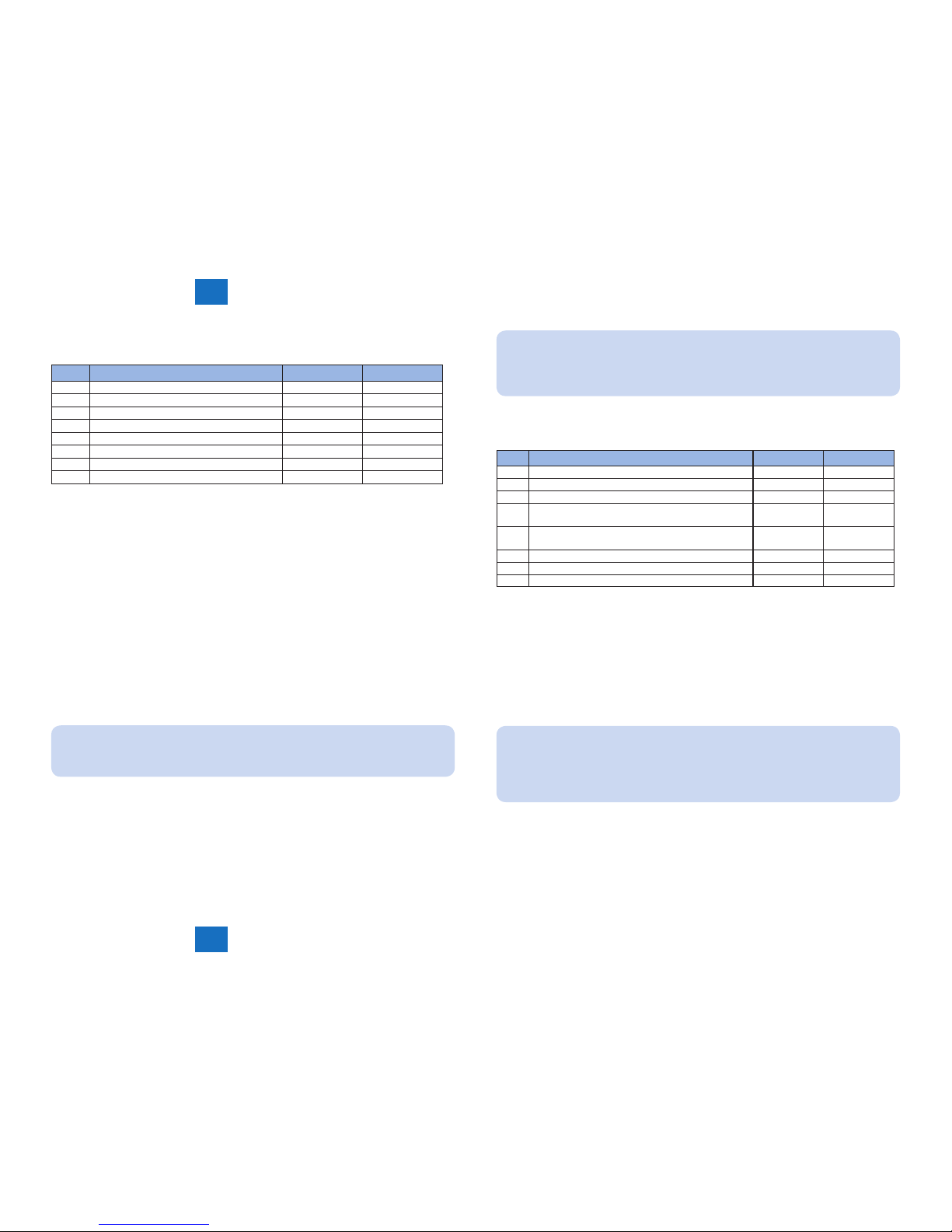
PCBs
[1]
[2]
No. Name Reference Adjastment during parts
replacement
[1] Super G3 FAX Board-AD2 (Refer to page 3-3)
[2] Speaker unit (Refer to page 3-6)
F-3-1
3
3
Parts Replacing and Cleaning
Parts Replacing and Cleaning
3-3
3-3
Parts Replacing and Cleaning > Parts Replacing > Removing the Fax Unit > Procedure
Parts Replacing and Cleaning > Parts Replacing > Removing the Fax Unit > Procedure
Parts Replacing
Removing the Fax Unit
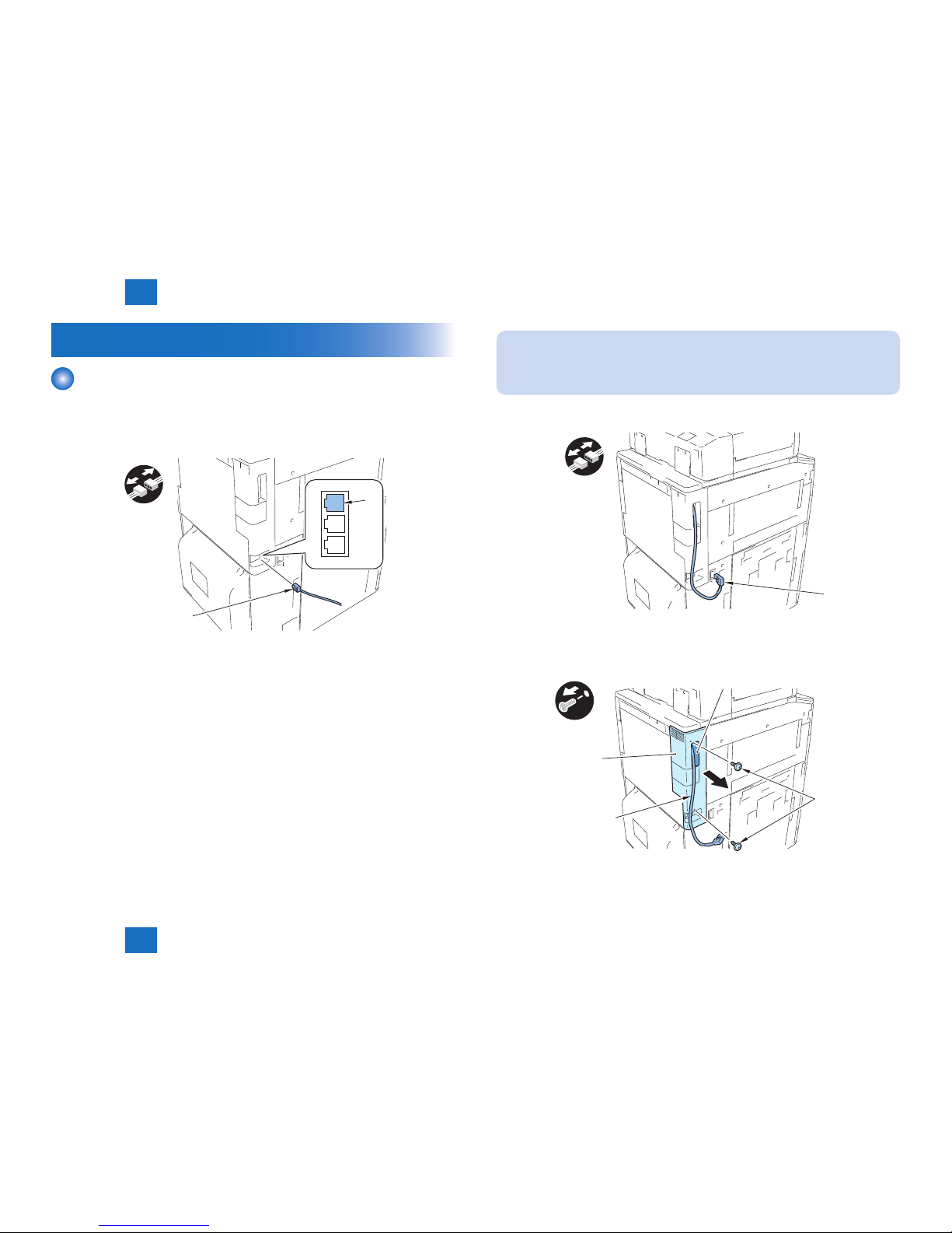
■Procedure
1) Disconnect one end of the Telephone Cord [1] from the modular jack (LINE 1) [2] on the
host machine.
[1]
[2]
F-3-2
NOTE:
Disconnect and then connect the Reader Power Supply Cable only in the case of iRADV C9075 PRO/C9070 PRO/C9065 PRO/C9060 PRO series and iR-ADV C7065/
C7055 series.
2) Disconnect the Reader Power Supply Cable [1].
[1]
3) Put the Reader Power Supply Cable [1] through the hole [A] in the Box Left Cover [2], and
then remove the cover.
• 2 Screws [3]
x2
[2]
[3]
[A]
[1]
F-3-3
F-3-4
3
3
Parts Replacing and Cleaning
Parts Replacing and Cleaning
3-4
3-4
Parts Replacing and Cleaning > Parts Replacing > Removing the Fax Unit > Procedure
Parts Replacing and Cleaning > Parts Replacing > Removing the Fax Unit > Procedure
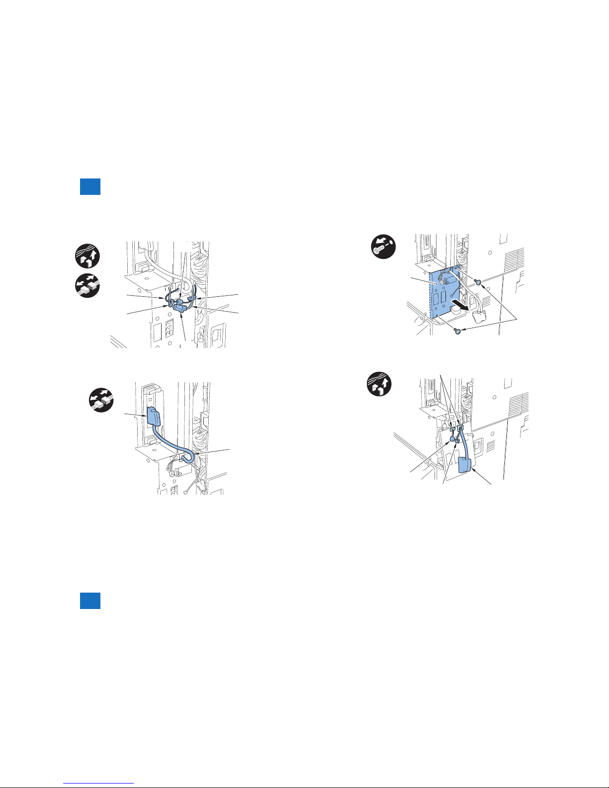
4) Disconnect the Arrestor Cable [1] and the Speaker Cable [2].
• 2 Wire Saddles [3]
• 2 Connectors [4]
x2
x2
[1]
[3]
[3]
[2]
[4]
[4]
5) Disconnect the cable [1] of the Fax Unit.
• 1 Connector [2]
[1]
[2]
F-3-5
F-3-6
6) Remove the Cover Support Plate [1].
• 2 Screws [2]
x2
[1]
[2]
7) Free the Arrestor Cable [1], Speaker Cable [2] and Fax Unit Cable [3] from the 2 Edge
Saddles [4] on the Cover Support Plate.
x2
[1]
[2]
[3]
[4]
F-3-7
F-3-8
3
3
Parts Replacing and Cleaning
Parts Replacing and Cleaning
3-5
3-5
Parts Replacing and Cleaning > Parts Replacing > Removing the Fax Unit > Procedure
Parts Replacing and Cleaning > Parts Replacing > Removing the Fax Unit > Procedure
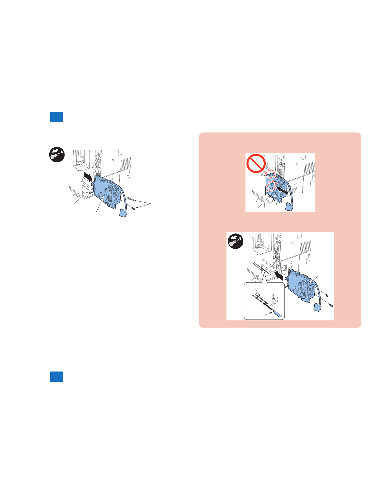
8) Remove the Fax Unit [1].
• 2 Screws [2]
[1]
[2]
x2
F-3-9
CAUTION:
• Install the Fax Unit [1] while paying attention not to trap the cables of the unit.
[1]
• Install the Fax Unit [1] by tting the protrusion [B] of the unit to the rail [A] of the host
machine.
x2
[1]
[A]
[B]
F-3-10
F-3-11

3
3
Parts Replacing and Cleaning
Parts Replacing and Cleaning
3-6
3-6
Parts Replacing and Cleaning > Parts Replacing > Removing the Speaker Unit > Procedure
Parts Replacing and Cleaning > Parts Replacing > Removing the Speaker Unit > Procedure
Removing the Speaker Unit
■Procedure
1) Open the Front Cover [1] and the Front Upper Cover [2].
[1]
[2]
2) Remove the 2 Hinge Shafts [1] and the Front Upper Cover [2].
[2]
[1]
[1]
F-3-12
F-3-13
3) Remove the Toner Container Replacement Unit Inner Cover [1].
• 4 Screws [2]
• 2 Claws [3]
[2]
[3]
x4
x2
[1]
[2]
4) Disconnect the Speaker Cable [1].
• 2 Wire Saddles [2]
• 1 Connector [3]
x2
[1]
[2]
F-3-14
F-3-15
3
3
Parts Replacing and Cleaning
Parts Replacing and Cleaning
3-7
3-7
Parts Replacing and Cleaning > Parts Replacing > Removing the Speaker Unit > Procedure
Parts Replacing and Cleaning > Parts Replacing > Removing the Speaker Unit > Procedure
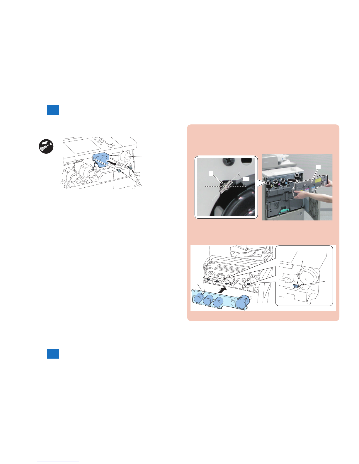
5) Remove the Speaker Unit [1].
• 2 Screws [2]
x2
[2]
[1]
F-3-16
CAUTION:
• When installing the Toner Container Replacement Unit Inner Cover [1], be sure to
install it while the 4 Parallel Pins [2] of the Inner Door Link Shaft are tilted at an angle
of approx. 45 degrees.
45°
[2]
[1]
• When installing the Toner Container Replacement Unit Inner Cover [1], be careful
not to damage the 4 Toner Insertion Inlet Cover Open/Close Sensors [2] and the 4
groundings [3] on the upper side of the sensors.
[2]
[3]
[1]
F-3-17
F-3-18

4
4
Error CodeError Code
Error Code
■Overview
■User Error Code
■Service Error Code

4
4
Error Code
Error Code
4-2
4-2
Error Code > Overview > Guide to Error Code
Error Code > Overview > Guide to Error Code
Overview
Guide to Error Code
When the Board has been installed and '1' is set for service data #1 SSSW SW01 bit 0,
communications ending in error will be indicated in the following reports using service error
codes: communications management report, reception result report, and error transmission
report.
You can also check the code of an error by making the following selections: System Monitor >
Fax > Detail.
The major error codes used by the Board are listed on the pages that follow. For information
on causes and remedies in connection with other error codes, see the "G3/G4 Facsimile Error
Code List" (HY8-23A0-020).
If the Board indicates a service error code, try the following:
- Increase the transmission level.
Set -8 (dBm) for service data #2 MENU parameter No. 007.
- Decrease the transmission level.
Set -15 (dBm) to service data #2 MENU parameter No. 007.
- Provide a remedy against echoes.
Change the following bit setting for service data #1 SSSW SW03:
Bit7 -> 1: to cause the machine to send a total signal before sending the CED signal.
-> 0: to causes the machine not to send a tonal signal before sending the CED signal.
- EPT (echo protect tone)
Change the setting of service data #1 SSSW SW03 bit 1:
Bit1 -> 1: to cause the machine to send EPT.
-> 0: to cause the machine not to send EPT.
- Adjust the NL equalizer.
Set '1' for serve data #2 MENU parameter No. 005.
- Decrease the transmission start speed.
Decrease the transmission start speed in user mode: System Settings > Communications
Settings > Fax Settings > Send Start Speed.
- Make the TCF evaluation standards lenient.
The Board does not offer a means by which to provide this remedy.
- Make the RTN transmissions conditions lenient.
Change parameters No. 2 through No. 004 of service data #3 NUMERIC Param.
No. 002: error rate for all lines; change it so that it is closer to 99%.
No. 003: number of lines in connection with bursts; change it so that it is closer to 99 lines.
No. 004: number of errors falling short of a specic number of lines in connection with
bursts; change it so that it is closer to 99.
- Increase the length of silence after reception of CFR.
Set '1' for service data #1 SSSW SW04 bit 4.
Bit4 -> 1: length of time during which a low-speed signal is ignored after transmission of
CFR; 1500 msec
-> 0: length of time during which a low-speed signal is ignored after transmission of
CFR; 700 msec

4
4
Error Code
Error Code
4-3
4-3
Error Code > Service Error Code
Error Code > Service Error Code
User Error Code
No. T/R Description
#001 [T] an original has jammed.
#003 [T/R] tine-out for copying or sending/receiving a single page has occurred.
#005 [T/R] time-out for initial identication (T0/T1) has occurred.
#008 [R] a mismatch of passwords at time of polling transmission has occurred.
#009 [R] recording paper has jammed or is absent.
#012 [T] recording paper is absent at the other party.
#018 [T/R] auto call initiation has failed.
#022 [T] call initiation has failed.
#037 [R] image memory overow at time of reception has occurred.
#080 [T] the other party has no F code reception function/or is not set to receive it.
#081 [T] the other party has no password reception function/or is not to receive it.
#099 [T/R] the Stop key is pressed while a communication is under way.
#102 [T/R] a mismatch of F-code/password has occurred.
#995 [T/R] a memory communication reservation has been cancelled.
T-4-1
Service Error Code
No. T/R Description
##100 [T] at time of transmission, the procedural signal has been transmitted more than
specied.
##101 [T/R] the modem speed does not match that of the other party.
##102 [T] at time of transmission, fall-back cannot be used.
##103 [R] at time of reception, EOL cannot be detected for 5 sec (15 sec if CBT).
##104 [T] at time of transmission, RTN or PIN is received.
##106 [R] at time of reception, the procedural signal is received for 6 sec while in wait for the
signal.
##107 [R] at time of reception, the transmitting party cannot use fall-back.
##109 [T] at time of transmission, a signal other than DIS, DTC, FTT, CFR, or CRP is received,
and the procedural signal has been sent more than specied.
##111 [T/R] memory error has occurred.
##114 [R] at time of reception, RTN is transmitted.
##200 [R] at time of reception, no image carrier is detected for 5 sec.
##201 [T/R] DCN is received outside the normal parity procedure.
##204 [T] DTC without transmission data is received.
##220 [T/R] system error (main program out of control) has occurred.
##223 [T/R] while a communication is under way, the line is cut.
##224 [T/R] in G3 communication, an error has occurred in the procedural signal.
##226 [T/R] the stack printer has fallen outside the RAM area.
##229 [R] the recording unit has remained locked for 1 min.
##232 [T] encoding error has occurred.
##237 [R] decoding error has occurred.
##238 [R] the print control unit is out of order.
##261 [T/R] system error has occurred.
##280 [T] at time of transmission, the procedural signal has been transmitted more than
specied.
##281 [T] at time of transmission, the procedural signal has been transmitted more than
specied.
##282 [T] at time of transmission, the procedural signal has been transmitted more than
specied.
##283 [T] at time of transmission, the procedural signal has been transmitted more than
specied.
##284 [T] at time of transmission, DCN is received after transmission of TCF.
##285 [T] at time of transmission, DCN is received after transmission of EOP.
##286 [T] at time of transmission, DCN is received after transmission of EOM.
##287 [T] at time of transmission DCN is received after transmission of MPS.
##288 [T] after transmission of EOP, a signal other than PIN, PIP, MCF, RTP, or RTN has been
received.
##289 [T] after transmission of EOM, a signal other than PIN, PIP, MCF, RTP, or RTN has been
received.
##290 [T] after transmission of MPS, a signal other than PIN, PIP, MCF, RTP, or RTN has been
received.

4
4
Error Code
Error Code
4-4
4-4
Error Code > Service Error Code
Error Code > Service Error Code
No. T/R Description
##670 [T] at time of V.8 late start, the V.8 ability of DIS front the receiving party is expected to be
detected, and the CI signal is expected to be transmitted in response; however, the
procedure fails to advance, and the line is released because of T1 time-out.
##671 [R] at time of V.8 arrival, procedure fails to move to phase 2 after detection of CM signal
from caller, causing T1 time-out and releasing line.
##672 [T] at time of V.34 transmission, a shift in procedure from phase 2 to phase 3 and
thereafter stops, causing the machine to release the line and suffer T1 timeout.
##673 [R] at time of V.34 reception, a shift in procedure from phase 2 to phase 3 and thereafter
stops, causing the machine to release the line and suffer T1 timeout.
##674 [T] at time of V.34 transmission, a shift in procedure from phase 3 and phase 4 to the
control channel and thereafter stops, causing the machine to release the line and
suffer T1 timeout.
##675 [R] at time of V.34 reception, a shift in procedure from phase 3 and phase 4 to the control
channel and thereafter stops, causing the machine to release the line and suffer T1
timeout.
##750 [T] at time of ECM transmission, no meaningful signal is received after transmission of
PPS-NULL, causing the procedural signal to be transmitted more than specied.
##752 [T] at time of ECM transmission, DCN is received after transmission of PPS-NULL.
##753 [T] at time of ECM transmission, the procedural signal has been transmitted more than
specied after transmission of PPS-NULL, or T5 time-out (60 sec) has occurred.
##754 [T] at time of ECM transmission, the procedural signal has been transmitted more than
specied after transmission of PPS-NULL.
##755 [T] at time of ECM transmission, no meaningful signal is received after transmission of
PPS-MPS, causing the procedural signal to be transmitted more than specied.
##757 [T] at time of ECM transmission, DCN is received after retransmission of PPS-MPS.
##758 [T] at time of ECM transmission, the procedural signal has been transmitted more than
specied after transmission of PPS-MPS, or T5 time-out (60 sec) has occurred.
##759 [T] at time of ECM transmission, the procedural signal has been transmitted more than
specied after transmission of PPS-MPS.
##760 [T] at time of ECM transmission, no meaningful signal is received after transmission of
PPS-EOM, causing the procedural signal to be transmitted more than specied.
##762 [T] at time of ECM transmission, DCN is received after transmission of PPS-EOM.
##763 [T] at time of ECM transmission, the procedural signal has been transmitted more than
specied after transmission of PPS-MPS, or T5 time-out (60 sec) has occurred.
##764 [T] at time of ECM transmission, the procedural signal has been transmitted more than
specied after transmission of PPS-EOM.
##765 [T] at time of ECM transmission, no meaningful signal is received after transmission of
PPS-EOP, causing the procedural signal to be transmitted more than specied.
##767 [T] at time of ECM transmission, DCN is received after transmission of PPS-EOP.
##768 [T] at time of ECM transmission, the procedural signal has been transmitted more than
specied after transmission of PPS-EOP, or T5 time-out (60 sec) has occurred.
##769 [T] at time of ECM transmission, the procedural signal has been transmitted more than
specied after transmission of PPS-EOP.
##770 [T] at time of ECM transmission, no meaningful signal is received after transmission of
EOR-NULL, causing the procedural signal to be transmitted more than specied.
##772 [T] at time of ECM transmission, DCN is received after transmission of EOR-NULL.
No. T/R Description
##773 [T] at time of ECM transmission, the procedural signal has been transmitted more than
specied after transmission of EOR-NULL, or T5 time-out (60 sec) has occurred.
##774 [T] at time of ECM transmission, ERR is received after transmission of EOR-NULL.
##775 [T] at time of ECM transmission, no meaningful signal is received after transmission of
EOR-MPS, causing the procedural signal to be transmitted more than specied.
##777 [T] at time of ECM transmission, DCN is received after transmission of EOR-MPS.
##778 [T] at time of ECM transmission, the procedural signal has been transmitted more than
specied after transmission EOR-MPS, or T5 time-out (60 sec) has occurred.
##779 [T] at time of ECM transmission, ERR is received after transmission of EOR-MPS.
##780 [T] at time of ECM transmission, no meaningful signal is received after transmission of
EOR-EOM, causing the procedural signal to be transmitted more than specied.
##782 [T] at time of ECM transmission, DCN is received after transmission of EOR-EOM.
##783 [T] at time of ECM transmission, the procedural signal has been transmitted more than
specied after transmission of EOR-EOM, or T5 time-out (60 sec) has occurred.
##784 [T] at time of ECM transmission, ERR is received after transmission of EOR-EOM.
##785 [T] at time of ECM transmission, no meaningful signal is received after transmission of
EOR-EOP, causing the procedural signal to be transmitted more than specied.
##787 [T] at time of ECM transmission, DCN is received after transmission of EOR-EOP.
##788 [T] at time of ECM transmission, the procedural signal has been transmitted more than
specied after transmission of EOR-EOP, or T5 time-out (60 sec) has occurred.
##789 [T] at time of ECM transmission, ERR is received after transmission of EOR-EOP.
##790 [R] at time of ECM reception, ERR is transmitted after transmission of EOR-Q.
##791 [T/R] while ECM mode procedure is under way, a signal other than a meaningful signal is
received.
##792 [R] at time of ECM reception, PPS-NULL cannot be detected over partial page processing.
##793 [R] at time of ECM reception, no effective frame is received while high-speed signal
reception is under way, thus causing time-out.
##794 [T] at time of ECM reception, PPR with all 0s is received.
##795 [T/R] a fault has occurred in code processing for communication.
##796 [T/R] a fault has occurred in decoding processing after reception of ECM
T-4-2

5
5
Service ModeService Mode
Service Mode
■Outline
■Details of Service Mode

5
5
Service Mode
Service Mode
5-2
5-2
Service Mode > Outline > Outline of Service Mode
Service Mode > Outline > Outline of Service Mode
Outline
Outline of Service Mode
The items that follow may be checked/set using the machine's service mode, which is
designed the way the service mode used in fax machines is designed in terms of contents
and operation.
#SSSW
Use it to register/set basic fax functions (e.g., error control, echo remedy, communication
error correction). Use it to make settings related counter functions.
#MENU
Use it to register/set items related to functions needed at time of installation (e.g., NL
equalizer, transmission level).
#NUMERIC
These setting items are for inputting numeric parameters such as the various conditions for
the RTN signal transmission.
#SPECIAL
These setting items are for telephone network control functions. Do not use.
#NCU
These setting items are for telephone network control functions such as the selection signal
transmission conditions and the detection conditions, for the control signals sent from the
exchange.
#FAX
Do not use.
#SCAN
These setting items are for image adjustment in scanning.
#PRINT
These setting items are for image adjustment in printer assembly and for special mode for the
eld-related measures.
#NETWORK
Use it to conrm the contents of the installed CA certicates.
#CODEC
This is a setting items related to CODEC.
#SYSTEM
This is a setting items related to SYSTEM.
#ACC
Register the accessories.
#COUNTER
Use it to check estimates for maintenance/parts replacement.
#LMS
Use it to set the inactivity of the transmitted license and the license inactivity without
transmitting.
#E-RDS
This is a setting items related to e-RDS (Embedded RDS).
#REPORT
Use it to generate reports on various service data.
#DOWNLOAD
Use it to download rmware to the ROM of a PCB in question.
#CLEAR
Use it to reset various data to initial settings.
#DISPLAY
The error and detailed code which have happened now are displayed.
Display the engine speed of the main controller PCB.
#ROM
Displays ROM information, such as version numbers and checksums.
#TEST MODE
Makes various status checks, such as contact sensor, sensor and print status.
5
5
Service Mode
Service Mode
5-3
5-3
Service Mode > Outline > Setting of Bit Switch > Outline
Service Mode > Outline > Setting of Bit Switch > Outline
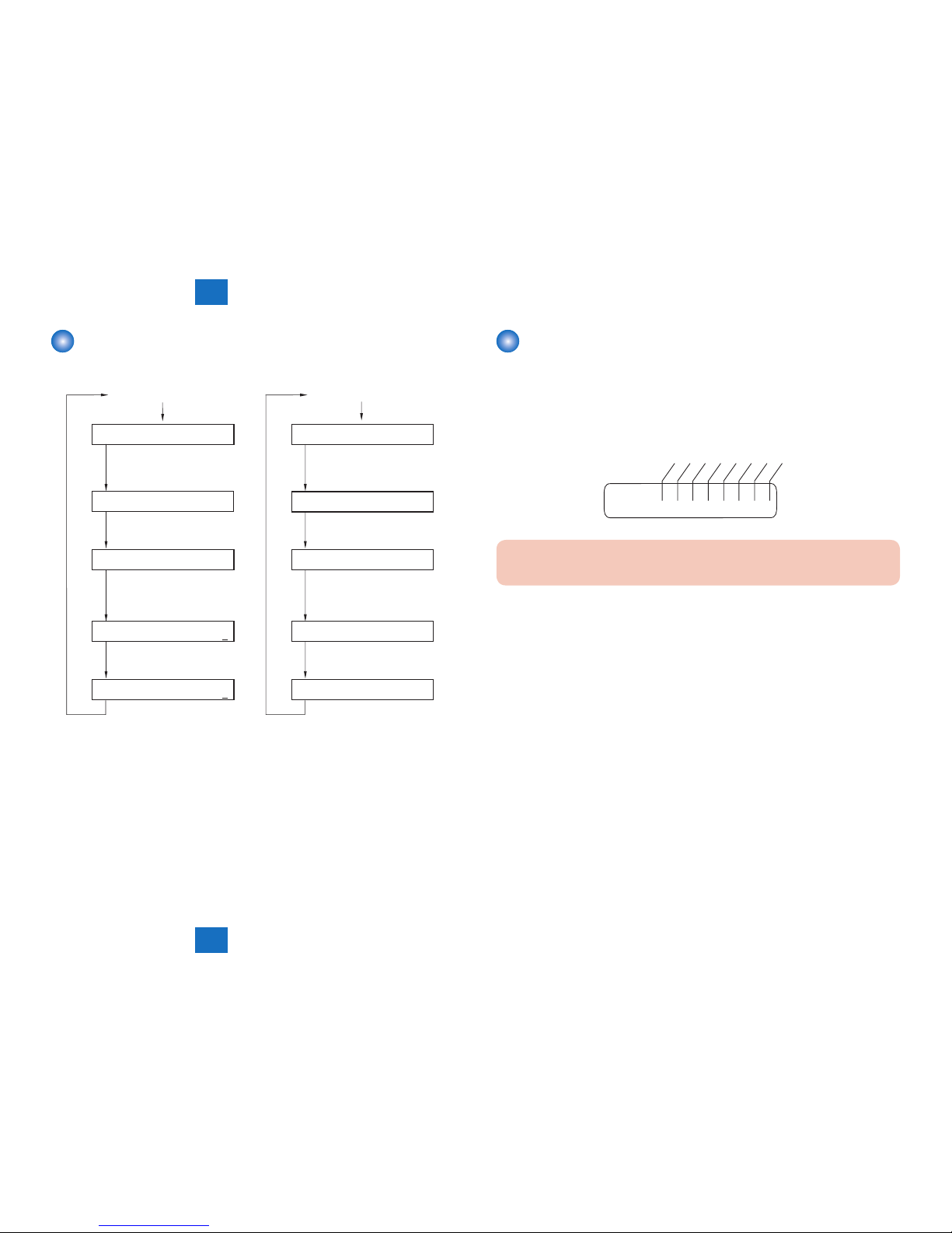
Using the Mode
#S SS W
# NU ME RI C
# NU ME RI C
2) Selecting a Menu Item
Select the Menu item using the
[left arrow]/[right arrow] on the
touch panel.
3) Press [OK].
5) Registering/Setting Data
Enter data using the keypad,
and then press [OK].
6) Press the [Stop]/[Additional
functions]/[Reset] key to end
the service mode.
# NU ME RI C
# NU ME RI C
0 0 1
0 0 1
0 0 2
0 0 2
0
0
10
4) Selecting a Prarameter
Select the Prarameter using the
[left arrow]/[right arrow].
1) Selecting Service Mode
# SS SW
3) Selecting a Menu Item
Press [OK].
2) Press [OK] on the
touch panel.
5) Registering/Setting Data
Enter data using the keypad,
and then press [OK].
6) Press the [Stop]/[Additional
functions]/[Reset] key to end
the service mode.
0 3 3
4) Selecting a Bit Switch
Select the bit using the
[left arrow]/[right arrow] on
the touch panel.
# SS SW
# SS SW
000000000
000000000
<Operation at the time of Bit SW> <Operation at the time of Parameter>
0 3 3
# SS SW
000000000
0 3 3
# SS SW
000000001
1) Selecting Service Mode
F-5-1
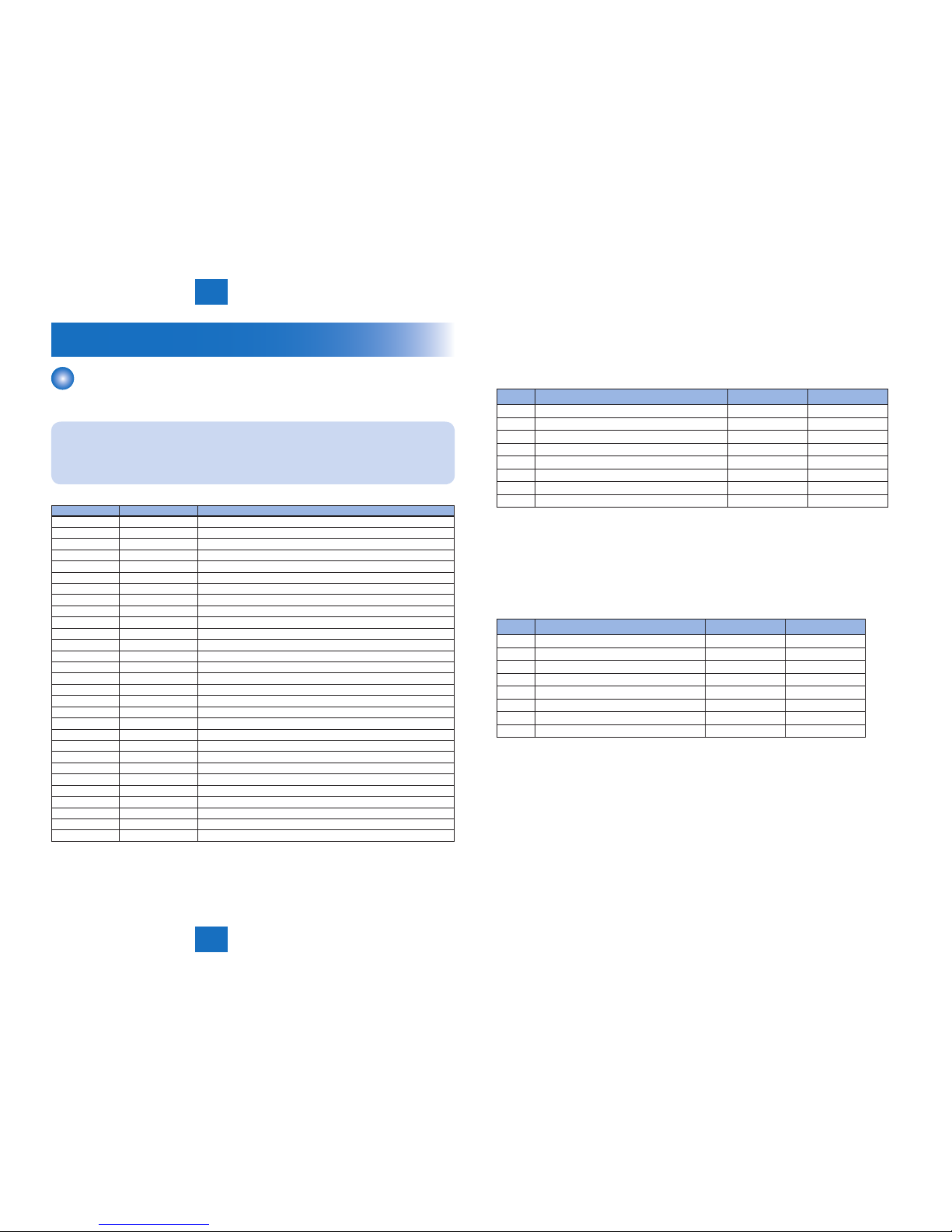
Setting of Bit Switch
■Outline
Bit Switch Composition
The items registered and set by each of these switches comprise 8-bit switches. The gure
below shows which numbers are assigned to which bits. Each bit has a value of either 0 or 1.
001
#SSSW
0 0 0 0 0 0 0 0
Bit 7
Bit 6
Bit 5
Bit 4
Bit 3
Bit 2
Bit 1
Bit 0
CAUTION:
Do not change service data identied as "not used"; they are set as initial settings.
F-5-2

5
5
Service Mode
Service Mode
5-4
5-4
Service Mode > Outline > Service Label
Service Mode > Outline > Service Label
Back-Up
At time of shipment from the factory, all machines are adjusted individually, and adjustment
values are recorded in their respective service labels.
If you have replaced the CIS unit or the DC controller PCB, or if you have initialized the RAM,
the adjustment values will return to their default settings. If there has been any change in a
service mode item, be sure to update its setting indicated on the service label. As necessary,
make use of the space in the service label (as when recording an item not found on the label).
Service Label
The item of service label is described below.
In this machine, the output of the service label does not support.
FACTORY
1 2 3
FACTORY
1 2 3
034 xxx ADJ-X-MG xxx
035 xxx
036 xxx W-PLT-X xxx
037 xxx W-PLT-Y xxx
038 xxx W-PLT-Z xxx
054 xxx 50_RG xxx
136 xxx 50_GB xxx
140 xxx 100_RG xxx
141 xxx 100_GB xxx
142 xxx MTF3-M1 xxx
143 xxx MTF3-M2 xxx
145 xxx MTF3-M3 xxx
146 xxx MTF3-M4 xxx
147 xxx MTF3-M5 xxx
148 xxx MTF3-M6 xxx
149 xxx MTF3-M7 xxx
150 xxx MTF3-M8 xxx
#SCAN> READER> ADJUST> ADJ-XY> MTF3-M9 xxx
ADJ-X xxx #SCA N> READER> ADJUST> PASCAL>
ADJ-Y xxx OFS T-P-K xxx
ADJ-S xxx #SCA N> FEEDER> ADJ
UST>
ADJ-Y-DF xxx DOCST xxx
STRD-POS xxx LA-SPEED xxx
DOC-LNGH xxx
Body No:
#PRINT> #PRINT NUMERIC> #SCAN> READER> ADJUST> ADJ-XY>
#SCAN> READER> ADJUST> CCD>
F-5-3
5
5
Service Mode
Service Mode
5-5
5-5
Service Mode > Details of Service Mode > #SSSW > Details
Service Mode > Details of Service Mode > #SSSW > Details
Details of Service Mode
#SSSW
■SSSW Composition
NOTE:
This document describes the default settings for the system for USA.
The default settings used in the service mode vary depending on the shipping
destination and model.
No. Initial setting Function
SW01 00000000 error/copy control
SW02 00010000 network connection setting
SW03 00000000 echo remedy setting
SW04 00000000 communication fault remedy setting
SW05 00000000 standard function (DIS signal) setting
SW06 10010000 read condition setting
SW7-SW11 not used
SW12 00000010 page timer setting
SW13 00000000 meter/inch resolution setting
SW14 00000001 inch/meter resolution setting
SW15 00000000 dial-in FAX/TEL switch-over function
SW16-SW17 not used
SW18 00000000 remedies for communication faults (2)
SW19-21 not used
SW22 00000000 fault remedy setting
SW23-24 not used
SW25 00000000 report indication resolution setting
SW26-27 not used
SW28 00000000 V.8/V.34 protocol settings
SW29 not used
SW30 00000000 Assigning a New Dial Tone Detection Method
SW31 not used
SW32 00000000 not used
SW33 00000000 counter function settings
SW34 00000011 waste toner full display setting
SW35 00001000 e-RDS function settings
SW36 00000000 Settings to disable auSend
SW37 11111111 Display settings for initialization menu after parts replacement 1
SW38 - SW50 not used
T-5-1
■Details
●SSSW-SW01
List of Functions
Bit Function 1 0
0 service error code output not output
1 not used - 2 not used - 3 not used - 4 not used - 5 not used - 6 not used - 7 not used - -
Detailed Discussions of Bit 0
Selects whether or not service error codes are output. When output is selected, service error
codes is report.
●SSSW-SW02
List of Functions
Bit Function 1 0
0 not used - 1 not used - 2 not used - 3 not used - 4 V34 CCRTN OFF Disable Not disable
5 not used - 6 not used - 7 F network silent termination service Compatible Not compatible
Detailed Discussions of Bit 4
V.34 control channel retrain can be disabled. When "1" is set, control channel retrain is not
started by the own machine.
Detailed Discussions of Bit 7
Select whether or not the machine is compatible with the F network (facsimile communication
network) silent termination service. When "Compatible" is selected, the machine automatically
receives a fax upon detection of the FC signal (1300 Hz tonal signal) without generating a
ringtone.
T-5-2
T-5-3
5
5
Service Mode
Service Mode
5-6
5-6
Service Mode > Details of Service Mode > #SSSW > Details
Service Mode > Details of Service Mode > #SSSW > Details
●SSSW-SW03
List of Functions
Bit Function 1 0
0 TCF criteria Loose Normal
1 Echo protect tone for high-speed transmission Transmitted Not transmitted
2 not used - 3 not used - 4 not used - 5 not used - 6 not used - 7 Tonal signal before CED signal transmission Transmitted Not transmitted
Detailed Discussions of Bit 0
Select whether to make the TCF criteria loose when the system with a V.34 modem receives
an image using the V.17 protocol.
When "Loose" is selected, fallback hardly occurs when an image is received using the V.17
protocol.
However, since the transmission speed is fast, erroneous lines can be generated after start
of image reception or the communication time can become long due to retransmission of
erroneous frames.
Detailed Discussions of Bit 1
Selects whether or not the echo protect tone is transmitted for high-speed transmission
(9600 or 7200 bps).
If errors due to line conditions occur frequently during fax transmission, select “Transmitted”.
When “Transmitted” is selected, a non-modulated carrier is transmitted as a synchronization
signal before the image transmission.
NOTE:
Codes for errors that can occur during transmission because of line conditions:
##100, ##104, ##281, ##282, ##283, ##750, ##755, ##760,##765
Detailed Discussions of Bit 7
Use it to enable/disable transmission of a 1080-Hz tonal signal before transmission of the
CED signal.
Select 'transmit' if errors occur frequently because of an echo when reception is from
overseas.
T-5-4
NOTE:
Any of the following error code may be indicated because of an echo at time of
reception
##0005, ##0101, ##0106, ##0107, ##0114, ##0200, ##0201, ##0790
●SSSW-SW04
List of Functions
Bit Function 1 0
0 not used - 1 Check CI frequency Yes No
2 the number of nal ag sequences of protocol signals 2 1
3 Reception mode after CFR signal transmission high speed high speed/low
speed
4 the length of the period of ignoring low speed signals
after CFR output
1500ms 700ms
5 Frequency of CI signal is checked when PBX is set. Yes No
6 CNG signal for manual transmission Not transmitted Transmitted
7 CED signal for manual reception Not transmitted Transmitted
Detailed Discussions of Bit 1
In automatic receiving, CI frequency check can be selected. If ‘Yes’ is selected, the upper and
lower limits of the CI frequency are checked, and automatic receiving can only go ahead if
both values meet German regulations.
Detailed Discussions of Bit 2
Use it to select the number of last ag sequences for a protocol signal (transmission speed at
300 bps). Select '2' if the other party fails to receive the protocol signal properly.
NOTE:
Any of the following error codes may be indicated at time of transmission
##0100, ##0280, ##0281, ##0750, ##0753, ##0754, ##0755, ##0758, ##0759, ##0760,
##0763 ##0764, ##0765, ##0768, ##0769,##0770, ##0773, ##0775, ##0778, ##0780,
##0783, ##0785, ##0788
Detailed Discussions of Bit 3
Use it to select an appropriate reception mode after transmission of the CFR signal.
If errors occur frequently at time of reception because of the condition of the line, select 'high
speed' for reception mode and, at the same time, selects 'do not receive' for 'ECM reception.'
T-5-5

5
5
Service Mode
Service Mode
5-7
5-7
Service Mode > Details of Service Mode > #SSSW > Details
Service Mode > Details of Service Mode > #SSSW > Details
NOTE:
Any of the following error codes may be indicated at time of reception because of line
condition
##0107, ##0114, ##0201
Be sure to change bit 4 before changing this bit; if errors still occur, change this bit.
When 'high speed' is selected, only high-speed signals (images) will be received after
transmission of the CFR signal.
Detailed Discussions of Bit 4
Use it to select the time length during which low-speed signals are ignored after transmission
of the CFR signal.
If the condition of the line is not good and, therefore, the reception of image signals is difcult,
select '1500 ms.'
Detailed Discussions of Bit 5
In the countries that need approval of CI signal frequency check, no checking on frequency
set at PBX when changing the frequency to PSTN setting and PBX
setting for frequency checks.
Detailed Discussions of Bit 6
Selects whether or not to transmit CNG signal during manual transmission.
In manual transmitting to a fax with the FAX/TEL switching mode, if there are frequent errors
due to failure to switch to fax mode, select "Transmitted" for the CNG signal.
Detailed Discussions of Bit 7
Selects whether or not to transmit CED signals during manual reception. If the other fax does
not transmit even when you start manual reception, select "Transmitted" for the CED signal.
●SSSW-SW05
List of Functions
Bit Function 1 0
0 not used - 1 Conversion from mm to inch (text mode) execute do not execute
2 Conversion from mm to inch (text/photo mode) execute do not execute
3 transmit bit 33 and thereafter for DIS signal prohibit do not prohibit
4 Recording paper length availability declared in DIS
signal
A4 size Arbitrary size
5 not used - 6 not used - 7 not used - -
T-5-6
Detailed Discussions of Bit 1
Use it to enable/disable millimeter/inch conversion in sub scanning direction for images read
in text mode.
Scanning direction in conversion follows the Bit 2 setting of SW14.
Detailed Discussions of Bit 2
Use it to enable/disable millimeter/inch conversion in sub scanning direction for images read
in text/photo mode while bit 1 is set to '1'.
Scanning direction in conversion follows the Bit 2 setting of SW14.
Detailed Discussions of Bit 3
Use it specify whether or not to transmit bit 33 and thereafter for the DIS signal.
If ‘prohibit’ is selected, Super Fine reception from a non-Canon machine can no longer be
used.
CAUTION:
If ‘prohibit’ is selected, Super Fine reception from a non-Canon machine can no longer
be used.
Detailed Discussions of Bit 4
Selects whether or not the recording paper length declared in the DIS signal is A4 size.
When receiving documents made up of long pages, to have the document divided into two
pages at the transmitting fax, select “A4 size”.
NOTE:
When “A4 size” is selected, this fax uses the DIS signal to tell the transmitting
fax that it is equipped with A4 size recording paper.
The transmitting fax that receives this DIS signal divides long pages into A4 size pages
before transmitting it to the receiving fax.
Some fax models do not so divide long documents.
 Loading...