


COPY
English
INSTRUCTION MANUAL
MODE D’EMPLOI
MANUAL DE INSTRUCCIONES
Français
Español

COPY
COPY
English
1

Introduction
COPY
The Canon Speedlite Transmitter ST-E3-RT is a transmitter for wireless
flash shooting. It can control up to 5 groups (15 units) of Canon
Speedlites that have a wireless multiple flash shooting function using
radio transmission. The transmitter also has dust and water resistance
equivalent to EOS-1D series cameras.
Read this instruction manual while also referring to the
instruction manuals of your camera and Speedlite.
Before using the transmitter, read this instruction manual and the
instruction manuals of your camera and Speedlite to familiarize
yourself with the operations.
Using the transmitter with a Camera
Using with an EOS digital camera (Type-A camera)
• You can perform wireless autoflash shooting with easy operations.
Using with an EOS film camera
• When using with an EOS film camera compatible with E-TTL II
and E-TTL autoflash systems (Type-A camera), you can perform
autoflash shooting with easy operations.
• This unit cannot be used with an EOS film camera with TTL
autoflash system (Type-B camera).
2

Chapters
COPY
Introduction
Getting Started
1
2
3
4
5
Preparations for wireless flash shooting
Wireless Flash Shooting: Radio Transmission
Wireless flash shooting with radio transmission
Setting Transmitter Functions with Camera
Operations
Setting the transmitter functions from the camera’s menu screen
Customizing the Transmitter
Customizing with Custom Functions and Personal Functions
Reference
System map, FAQ
2
11
15
47
53
59
3

Contents
COPY
Introduction 2
Chapters ...................................................................................................3
Nomenclature............................................................................................6
Conventions Used in this Manual ...........................................................10
Getting Started 11
1
Installing the Batteries.............................................................................12
Attaching and Detaching the Transmitter................................................13
Turning on the Power..............................................................................13
Wireless Flash Shooting: Radio Transmission 15
2
' Wireless Flash Shooting ....................................................................16
Wireless Settings ....................................................................................20
a: Fully Automatic Wireless Flash Shooting...................................24
Using Fully Automatic Wireless Flash.....................................................27
a: Wireless Multiple Flash Shooting with Flash Ratio ....................31
q: Wireless Multiple Flash Shooting with Manual Flash Output ............34
[: Shooting with a Different Flash Mode for Each Group .....................38
Clearing Transmitter Settings .................................................................40
Test Flash from a Slave Unit...................................................................40
Modeling Flash........................................................................................41
Remote Release from a Slave Unit.........................................................42
Linked Shooting ......................................................................................43
Setting Transmitter Functions with Camera Operations 47
3
Transmitter Control from Camera’s Menu Screen ..................................48
4

Customizing the Transmitter 53
COPY
4
C / >: Setting Custom and Personal Functions............................ 54
C: Setting Custom Functions ............................................................ 56
>: Setting Personal Functions........................................................... 58
Reference 59
5
ST-E3-RT System .................................................................................. 60
Troubleshooting Guide........................................................................... 61
Specifications ......................................................................................... 64
Index ...................................................................................................... 70
Contents
5
Nomenclature
COPY
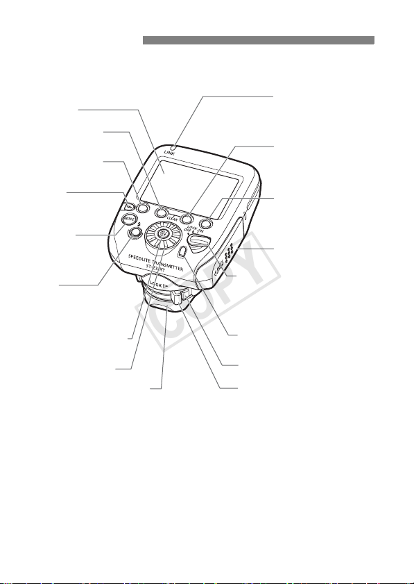
LCD panel
Function button 2
Function button 1
<D>
Radio transmission
confirmation lamp
(p.21, 23, 25, 30, 45)
Function button 3
<I>
Linked shooting
button (p.44)
<E >
Flash mode button
(p.24, 34, 35, 38)
<Q >
Charge lamp/
Test flash button
(p.13, 25, 56)
<8> Select/Set button
<9> Select dial
Dust- and water-resistant
adapter
6
Power switch (p.13)
<K> : Power on
<a> : Button/dial lock
(Power on)
<J> : Power off
Flash exposure
confirmation lamp (p.25)
Lock-release button (p.13)
Mounting foot lock lever (p.13)
Function button 4
Battery compartment
cover (p.12)
Nomenclature 02
COPY
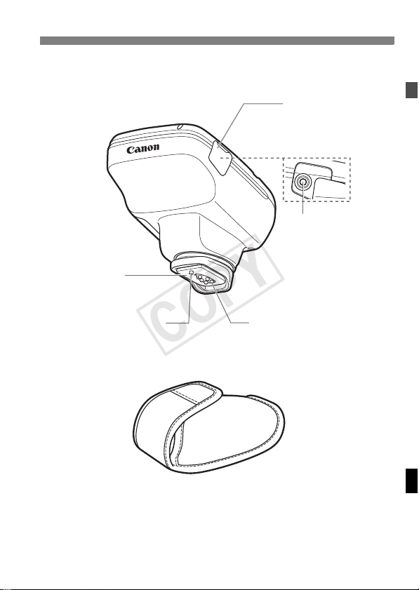
Mounting foot
(p.13)
Terminal cover
Remote release
terminal (p.42)
Nomenclature
Locking pin
Contacts
Case
7
Nomenclature
COPY
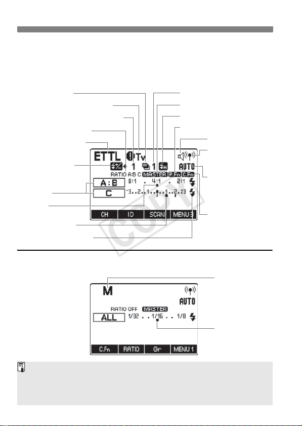
LCD panel
Radio transmission wireless shooting
E-TTL II/E-TTL autoflash (p.24)
: FEB (p.28, 50)
g
: Sync speed warning (p.19)
k
Flash exposure compensation amount
: Flash ratio (p.31)
,
: E-TTL II/E-TTL
a
autoflash
: Flash exposure
f
compensation
(p.27, 50)
Firing group
Flash ratio
Flash exposure level
: Slave flash ready (p.25)
Q
Manual flash (p.34)
(p.15)
FEB sequence (p.56)
: Master (p.20)
M
: High-speed sync
c
: Personal Functions (p.58)
T
Beep
: Radio
'
transmission
wireless shooting
: Channel
*
)
(p.21, 22)
: Custom
u
q
Manual flash output
: Channel
automatic
setting
Functions (p.56)
: Manual Flash
The display will show only the settings currently applied.
The functions displayed above function buttons 1 to 4, such as <=>
and <@>, change according to the setting’s status.
When a button or dial is operated, the LCD panel illuminates (p.14).
8
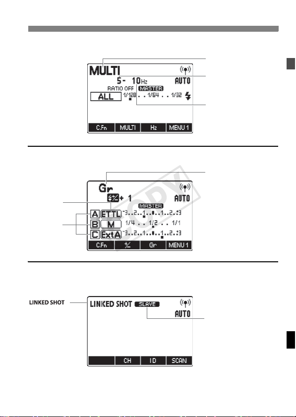
Stroboscopic flash (p.35)
COPY
Group firing (p.38)
Flash mode
Firing group
Linked shooting (p.43)
Nomenclature
:
?
Multi (Stroboscopic) flash
Number of flashes
Flash frequency
: Group flash
[
Linked shooting
:
: Slave
x
: Master
M
9

Conventions Used in this Manual
COPY
Icons in this Manual
9 : Indicates the selection dial.
8 : Indicates the select/set button.
3/1/2 : Indicates that the respective function remains active
(p.**) : Reference page numbers for more information.
Basic Assumptions
The operation procedures assume that the power switches of the
camera, transmitter and Speedlite are already set to <K>.
The icons used for buttons, dials and symbols in the text match the
icons found on the camera, transmitter and Speedlite.
The operation procedures assume that the menu and Custom
Functions of the camera and the Custom Functions and Personal
Functions of the transmitter and the Speedlite are at their default
settings.
All figures are based on the use of two AA/LR6 alkaline batteries and
Canon’s testing standards.
for 4 sec., 6 sec. or 16 sec. after you let go of the
button.
: Warning to prevent shooting problems.
: Supplemental information.
10

1
COPY
Getting Started
This chapter describes the preparations before starting
wireless flash shooting.
11
Installing the Batteries
COPY
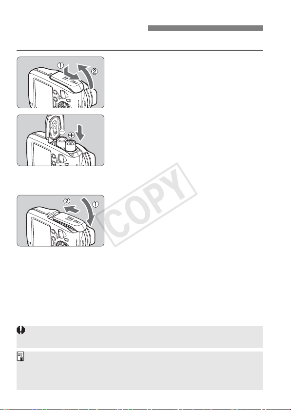
Install two AA/LR6 batteries.
Open the cover.
1
Slide the cover down as shown in "
and open the battery compartment
cover.
Install the batteries.
2
Make sure the + and – battery
contacts are correctly oriented as
shown in the battery compartment.
The grooves on the side surfaces of
the battery compartment indicate –.
This is convenient when replacing the
batteries in a dark place.
Close the cover.
3
Close the battery compartment cover
and slide it up.
Slide the cover until it clicks in place.
Wireless Flash Shooting Time
You can perform wireless flash shooting for approx. 10 hours*
continuously.
* Based on new AA/LR6 alkaline batteries and Canon’s testing standards.
Using AA/LR6 batteries other than the alkaline type may cause improper
battery contact due to the irregular shape of the battery contacts.
When <!> is displayed, replace the batteries with new ones.
Use a new set of two batteries of the same brand. When replacing the
batteries, replace both batteries at once.
AA/LR6 rechargeable Ni-MH or lithium batteries can also be used.
12
Attaching and Detaching the Transmitter
COPY
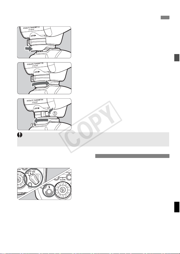
Attach the transmitter.
1
Slip the transmitter’s mounting foot
all the way into the camera’s hot
shoe.
Secure the transmitter.
2
On the mounting foot, slide the lock
lever to the right.
X When the lock lever clicks in place, it
will be locked.
Detach the transmitter.
3
While pressing the lock-release
button, slide the lock lever to the left
and detach the transmitter.
Before attaching or detaching the transmitter, be sure to turn the transmitter
power off.
Turning on the Power
Set the power switch to <K>.
X The LCD panel illuminates.
The charge lamp lights when the
wireless shooting (slave) is ready.
During wireless shooting, press the
transmitter’s charge lamp (test flash
button) to fire a test flash.
13

Turning on the Power
COPY
About Auto Power Off
To save battery power, the power will turn off automatically after 5 min.
of idle use. To turn on the transmitter again, press the camera’s shutter
button halfway, or press the test flash button (charge lamp).
About the Lock Function
By setting the power switch to <a>, you can disable flash’s button
and dial operations. Use this to prevent the transmitter function settings
from being accidentally changed after you set them.
If you operate a button or dial, <LOCKED> is displayed on the LCD
panel (the functions displayed above function buttons 1 to 4, such as
<=> and <@>, are not displayed).
About the LCD Panel Illumination
When a button or dial is operated, the LCD panel illuminates in green
for 12 sec. When setting a function, the illumination continues until the
setting is complete.
If the transmitter is the master unit in linked shooting, the LCD panel
illuminates in green. If the transmitter is a slave unit, it illuminates in
orange.
You cannot use the test flash while the camera’s 3/1/2 timer is
operating.
The transmitter settings are stored even when the power is turned off. To
retain the settings when replacing the batteries, replace the batteries
within 1 min. of turning off the power switch and removing the batteries.
You can fire a test flash even when the power switch is set to the
<a> position. Also, when a button or dial is operated, the LCD panel
illuminates.
You can set a beep to sound when the slave unit is fully charged
(C.Fn-20/p.57).
Auto power off can be disabled (C.Fn-01/p.56).
You can change the duration of the LCD panel illumination (C.Fn-22/p.57).
You can change the color of the LCD panel illumination (P.Fn-03, 04/p.58).
14

2
COPY
Wireless Flash Shooting:
Radio Transmission
This chapter describes wireless flash shooting.
For the accessories required for wireless shooting,
see the system map (p.60). For the regions of use,
restrictions, and precautions related to radio
transmission, refer to the separate leaflet.
When the camera’s shooting mode is set to a fully automatic
mode or an Image Zone mode, the operations in this chapter
are not available. Set the camera’s shooting mode to V/X/
W/q/5 (Creative Zone mode).
The transmitter attached to the camera is called the master unit,
and a flash that is wirelessly controlled is called the slave unit.
15
' Wireless Flash Shooting
COPY
Using a transmitter and a Canon Speedlite compatible with radio
transmission wireless shooting makes it easy to shoot with advanced
wireless multiple flash lighting, in the same way as normal E-TTL II/
E-TTL autoflash shooting.
The system is designed so that the settings of the transmitter attached
to the camera (master) are automatically reflected on the Speedlite that
is wirelessly controlled (slave). Therefore, you do not need to operate
the slave unit while shooting.
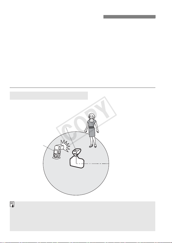
The basic relative positions and operating range are as shown in the
figure. You can then perform wireless E-TTL II/E-TTL autoflash
shooting just by setting the master unit to <a>.
Positioning and Operation Range
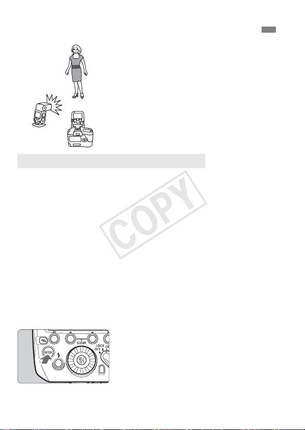
Autoflash Shooting Using One Slave Unit (p.24)
M
x
Position the slave unit using the mini stand supplied with the flash.
Before shooting, perform a test flash (p.13) and test shooting.
The transmission distance may be shorter depending on the conditions
such as the positioning of slave units, the surrounding environment and
weather conditions.
16
(Example of wireless flash shooting)
Transmission distance
Approx. 30 m (98.4 ft.)
' Wireless Flash Shooting
COPY
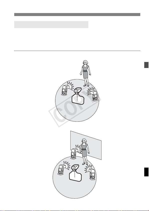
Wireless Multiple Flash Shooting
You can divide the slave units into two or three groups and perform
E-TTL II/E-TTL autoflash shooting while changing the flash ratio
(factor). In addition, you can set and shoot with a different flash mode
for each firing group, for up to 5 groups.
Autoflash Shooting with Two Slave Groups (p.31)
A
B
Autoflash Shooting with Three Slave Groups (p.32)
C
A
B
17
' Wireless Flash Shooting
COPY
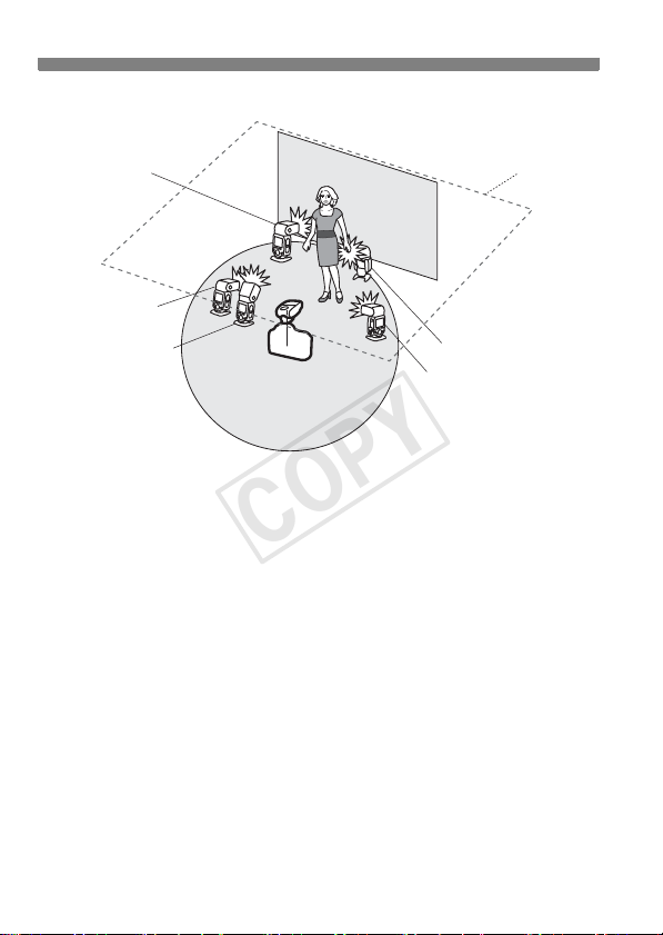
Shooting with a Different Flash Mode set for Each Group
(p.38)
Auto external
flash metering
E-TTL II
Manual flash
E
A
B
Ceiling
D
C
* The flash mode settings are
Manual flash
Manual flash
indicated only as an example.
18

' Wireless Flash Shooting
COPY
About Restrictions on Functions Depending on
the Camera Used
When performing radio transmission wireless flash shooting,
restrictions may apply to the flash mode, maximum flash sync speed
(referred to below as the “flash sync speed”) and high-speed sync
function, depending on the camera that you use.
EOS digital cameras released since 2012
When using the transmitter in combination with a camera such as
the EOS-1D X, you can shoot without any restrictions on the flash
mode and maximum flash sync speed.
EOS cameras compatible with E-TTL autoflash and released up
to 2011
When using the transmitter with the cameras listed below,
transmission wireless shooting with E-TTL autoflash is not
available. Shoot with manual flash (p.34) or stroboscopic flash
(p.35).
EOS-1Ds, EOS-1D, EOS-1V, EOS-3, EOS ELAN II(E)/
EOS 50(E), EOS REBEL 2000/EOS 300, EOS REBEL G/
EOS 500N, EOS 66/EOS Rebel XS N/EOS 3000 N, EOS IX(E),
EOS IX Lite/EOS IX 7
Also, when using the transmitter with a film or digital camera
released up to 2011, the following restrictions apply.
1. The flash sync speed is 1 increment slower
Check the flash sync speed (X = 1/*** sec.) of your camera, and
shoot with a shutter speed up to a maximum of 1 stop slower
than the flash sync speed (Example: When X = 1/250 sec., radio
transmission wireless shooting is possible from 1/125 sec. to 30
sec.). Also, high-speed sync shooting is not possible.
you set the shutter speed 1 increment slower than the flash sync
speed, the <k> warning icon will disappear.
2. Group flash is not possible
(p.38).
radio
When
19
Wireless Settings
COPY
To perform wireless shooting, set the transmitter (master unit) and flash
(slave unit) with the following procedure.
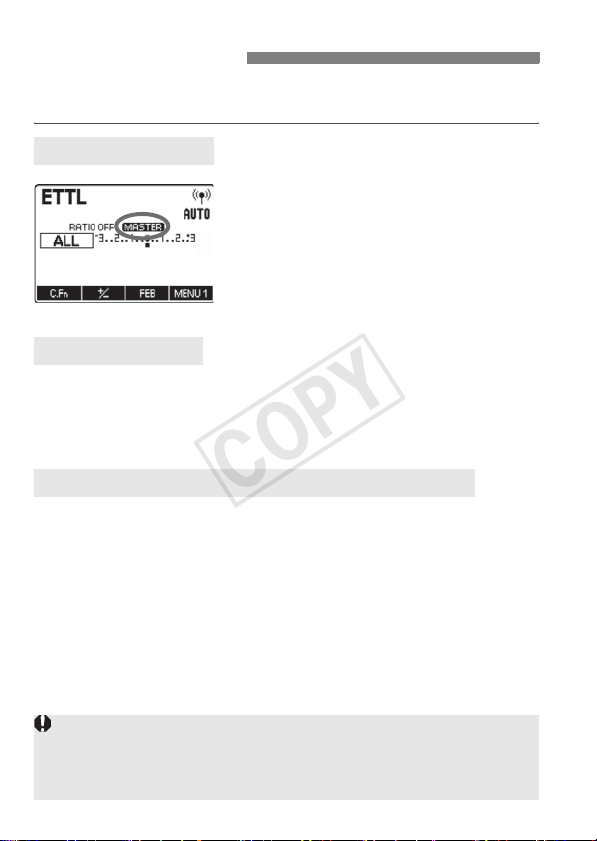
Master Unit Setting
Check that <M> is
displayed.
Check that <M> is displayed
at the position shown in the figure.
Slave Unit Setting
Set a flash that is compatible with radio transmission wireless
flash shooting as the slave unit.
For the slave unit settings, see the flash’s instruction manual.
Transmission Channel/Wireless Radio ID Settings
To avoid interference with wireless multiple flash systems using radio
transmission that are used by other photographers, or with other
devices that use radio waves (wireless), you can change the
transmission channel and wireless radio ID. Set the same channel
and ID for both the master unit and slave unit.
When establishing multiple radio transmission wireless flash systems,
interference between flash systems may occur, even if the flashes are set to
different channels. Set different radio transmission IDs for each channel
(p.21).
20
Wireless Settings
COPY
Setting the Master Unit Transmission Channel / Wireless
Radio ID
Use the following procedure to set the master unit’s transmission
channel and wireless radio ID. Set the same channel and ID for both the
master unit and slave unit. For the slave unit settings, see the flash’s
instruction manual.
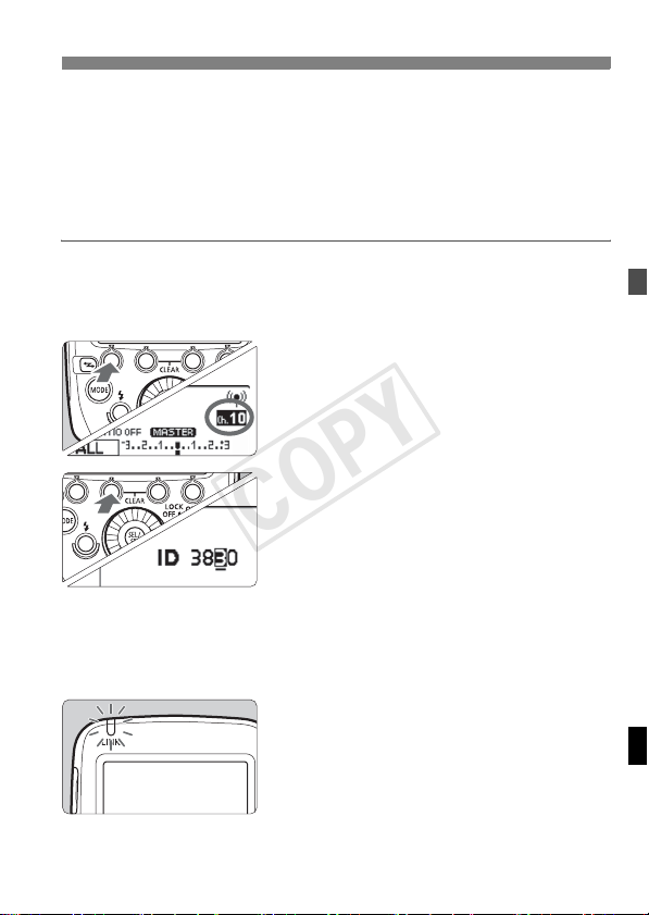
Display <O>.
1
Press function button 4 to display
<O>.
Set a channel.
2
Press function button 1 <C>.
Turn <9> to select “AUTO” or a
channel from Ch. 1 to 15, and press
the <8> button.
Set a wireless radio ID.
3
Press function button 2 <H>.
Turn <9> to select the position
(digit) to set, and press the <8>
button.
Turn <9> to select a number from 0
to 9, and press the <8> button.
Repeat step 3 to set a 4-digit number.
Press function button 4 <?> to
return to the shooting-ready state.
X When transmission between the
master unit and slave unit is
established, the <D> lamp is lit in
green.
21
Wireless Settings
COPY
Scanning the Master Unit Transmission Channels to Set
You can scan the radio reception status and set the master unit’s
transmission channel automatically or manually. When the channel is
set to “AUTO”, the channel with the best reception signal is
automatically set. When setting the channel manually, you can set the
transmission channel again while referring to the scan results.
Scanning while “AUTO” is set
Run the scan.
Press function button 4 to display
<O>.
Press function button 3 <W>.
X
The channel is reset to one with a
good reception signal.
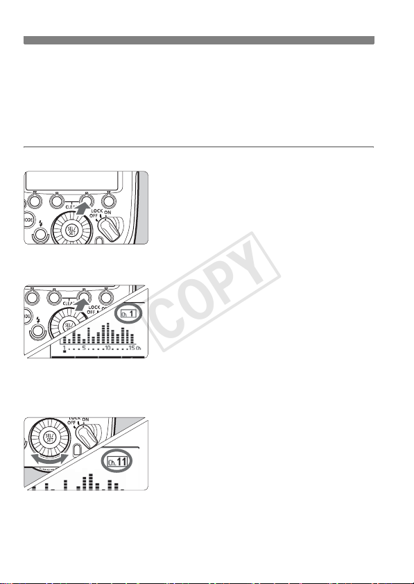
Scanning while Ch. 1 to 15 is set
Run the scan.
1
Press function button 4 to display
<O>.
Press function button 3 <W>.
X The radio reception status is
displayed in a graph.
The higher the peak of the channel in
the graph, the better the radio
reception signal.
Set a channel.
2
Turn <9> to select a channel from
Ch. 1 to 15.
Press the <8> button to set the
channel and return to the shootingready state.
22

Wireless Settings
COPY
About the <D> Lamp
The color of the <D> lamp changes depending on the transmission
status of the master unit and the slave unit.
Color Status Description Action
Green Lit
Red
Blinking
If the transmission channels of the master unit and slave unit are
different, the slave unit does not fire. Set both to the same number, or set
both to “AUTO”.
If the wireless radio IDs of the master unit and slave unit are different, the
slave unit does not fire.
Transmission
OK
Lit
Not connected Check the channel and ID
Too many units
Error Turn the power off and on again
Master units + slave units =
16 units or less
–
About the Memory Function
You can save the wireless settings and recall the settings later.
Press function button 4.
1
Press function button 4 to display
<P>.
Save or load the settings.
2
Press function button 3 <L>.
[Save]
Press function button 1 <V>.
X The settings are saved (stored in the
memory).
[Load]
Press function button 2 <J>.
X The settings that were saved are set.
23
a
COPY
Autoflash Shooting Using One Slave Unit
: Fully Automatic Wireless Flash Shooting
This section describes basic fully
automatic wireless shooting when using
a transmitter attached to the camera
(master) and a wirelessly controlled flash
(slave).
Set the flash as the slave unit.
1
For the slave unit settings, see the
flash’s instruction manual.
Set A, B or C as the firing group. The
flash will not fire if it is set to D or E.
Check the channel and ID.
2
If the channels and IDs of the master
unit and slave unit are different, set
them to the same numbers (p.21, 22).
Position the camera and the
3
flash.
Position them within the range shown
on page 16.
Set the flash mode to <a>.
4
Press the <E> button on the
master unit and set the flash mode to
<a>.
The slave unit is set automatically to
<a> during shooting via the
control from the master unit.
24

a: Fully Automatic Wireless Flash Shooting
COPY
Check the transmission status
5
and that the flash is ready.
Check that the <D> lamp is lit in
green.
When the slave flash is ready, the
AF-assist beam emitter blinks at
1-second intervals.
Check that the <Q> slave flash-ready
icon is lit on the master unit’s LCD
panel.
When the recycling of all the flash
units is completed, the master unit's
charge lamp lights.
Check the operation.
6
Press the master unit’s test flash
button (charge lamp).
X The slave unit flashes. If the slave
unit does not fire, check that it is
placed within the operation range.
Take the picture.
7
Set the camera and take the picture,
in the same way as with normal flash
shooting.
X If a standard flash exposure was
obtained, the flash exposure
confirmation lamp lights for 3 sec.
If the <D> lamp is red, radio transmission has not been established.
Check again the transmission channels and wireless radio IDs of the master
unit and slave unit. If you cannot connect with the same settings, turn the
power off and on again.
25

a: Fully Automatic Wireless Flash Shooting
COPY
Autoflash Shooting Using Multiple Slave Units
When you need more flash output or you
want to perform lighting more easily, you
can increase the number of slave units
and fire them as a single flash.
To add slave units, use the same
procedure as “Autoflash Shooting Using
One Slave Unit”. Set A, B or C as the
firing group. The flash will not fire if it is
set to D or E.
When the number of slave units is
increased, automatic control is
performed to fire all flashes at the same
flash output and ensure that the total
flash output results in the standard
exposure.
You can press the depth-of-field preview button on the camera to fire the
modeling flash (p.41).
If the slave unit’s auto power off takes effect, press the master unit’s test
flash button (p.13) to turn on the slave unit. Note that the test flash cannot
be fired while the camera’s metering timer is operating.
The autoflash system (E-TTL II/E-TTL) depends on the camera used and
is set automatically. Note that <a> is displayed on the LCD panel for
both systems.
You can enable a beep to sound when the charge of all the slave units is
complete (C.Fn-20/p.57).
26
Using Fully Automatic Wireless Flash
COPY
Flash exposure compensation and other settings set on the transmitter
(master unit) will also be automatically set in the flash (slave unit). You
do not need to operate the slave unit.
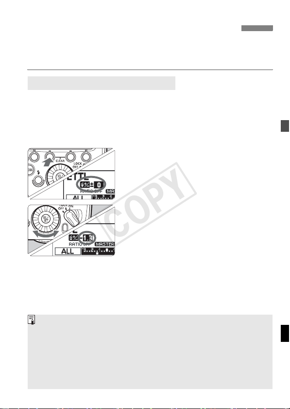
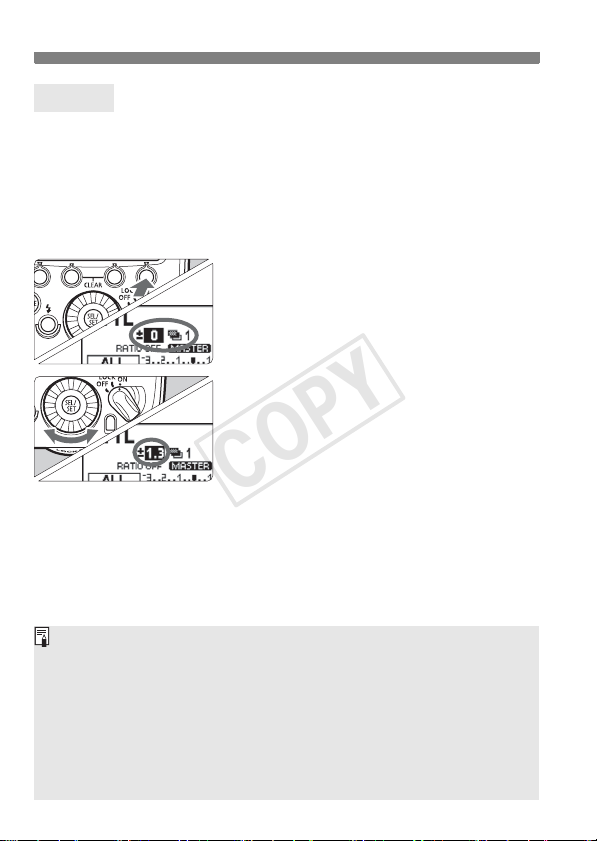
f Flash Exposure Compensation
In the same way as normal exposure compensation, you can set
exposure compensation for flash. The flash exposure compensation
amount can be set up to ±3 stops in 1/3-stop increments.
Display <M>.
1
Press function button 4 to display <
Press the <@> button.
2
Press function button 2 <@>.
X <f> is displayed and the flash
exposure compensation amount is
highlighted.
Set the flash exposure
3
compensation amount.
Turn <9> to set the flash exposure
compensation amount, and press <
X The flash exposure compensation
amount is set.
“0.3” indicates 1/3 stops and “0.7”
indicates 2/3 stops.
To cancel flash exposure compensation,
return the compensation amount to “±0”.
M
8
>.
>.
Generally, set an increased exposure compensation for bright subjects
and set a decreased exposure compensation for dark subjects.
If the camera’s exposure compensation is set to 1/2-stop increments, flash
exposure compensation will be up to ±3 stops in 1/2-stop increments.
When the flash exposure compensation is set on both the transmitter and
the camera, the transmitter setting is given priority.
The flash exposure compensation amount can be set directly with <9>
without pressing the button (C.Fn-13/p.57).
27
Using Fully Automatic Wireless Flash
COPY
g FEB
You can take three shots while automatically changing the flash output.
This is called FEB (Flash Exposure Bracketing). The settable range is
up to ±3 stops in 1/3-stop increments.
Display <M>.
1
Press function button 4 to display
<M>.
Press the <E> button.
2
Press function button 3 <E>.
X <g> is displayed and the FEB level
display is highlighted.
Set the FEB level.
3
Turn <9> to set the FEB level, and
press <8>.
X The FEB level is set.
“0.3” indicates 1/3 stops and “0.7”
indicates 2/3 stops.
When used together with flash exposure
compensation, FEB shooting is
performed based on the flash exposure
compensation amount.
After the three shots are taken, FEB is canceled automatically.
Before shooting with FEB, it is recommended to set the camera’s drive
mode to single shooting and check that the flash is recycled.
You can use FEB together with flash exposure compensation or FE lock.
If the camera’s exposure compensation is set to 1/2-stop increments, flash
exposure compensation will be up to ±3 stops in 1/2-stop increments.
You can set FEB to remain enabled automatically after shooting the three
shots (C.Fn-03/p.56).
You can change the FEB shooting sequence (C.Fn-04/p.56).
28