

Staple Finisher-S1
Product Outline
Technology
Periodic Servicing
Parts Replacement and Cleaning Procedure
Adjustment
Installation
Appendix
Service Manual Rev. 1.0
654321

Application
This manual has been issued by Canon Inc. for qualied persons to learn technical theory,
installation, maintenance, and repair of products. This manual covers all localities where the
products are sold. For this reason, there may be information in this manual that does not
apply to your locality.
Corrections
This manual may contain technical inaccuracies or typographical errors due to improvements
or changes in products. When changes occur in applicable products or in the contents of this
manual, Canon will release technical information as the need arises. In the event of major
changes in the contents of this manual over a long or short period, Canon will issue a new
edition of this manual.
The following paragraph does not apply to any countries where such provisions are
inconsistent with local law.
Trademarks
The product names and company names used in this manual are the registered trademarks
of the individual companies.
Copyright
This manual is copyrighted with all rights reserved. Under the copyright laws, this manual may
not be copied, reproduced or translated into another language, in whole or in part, without the
consent of Canon Inc.
© CANON INC. 2014
Caution
Use of this manual should be strictly supervised to avoid disclosure of condential
information.
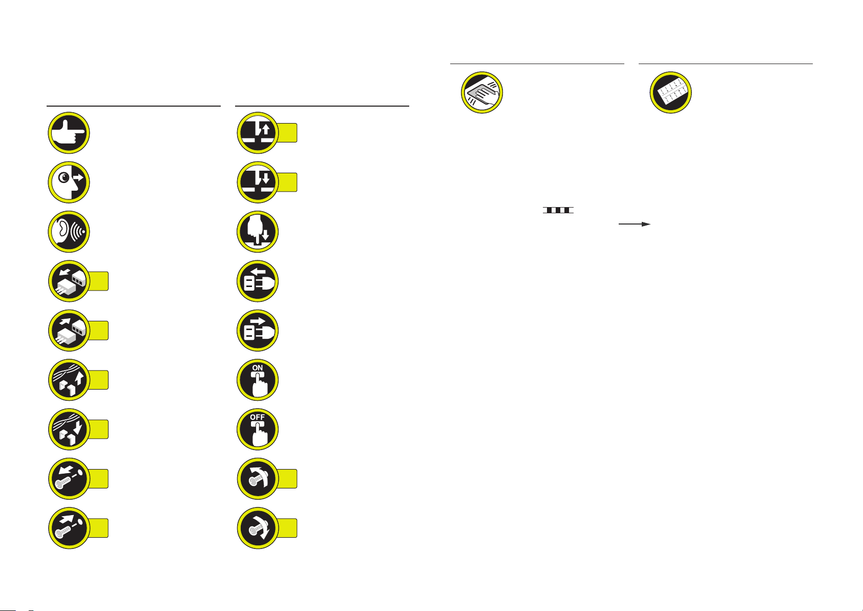
Explanation of Symbols
The following symbols are used throughout this Service Manual.
Symbols Explanation Symbols Explanation
Symbols Explanation Symbols Explanation
Check.
Check visually.
Check a sound. Push the part.
Disconnect the connector. Connect the power cable.
1x
Connect the connector.
1x
Remove the cable/wire
from the cable guide or wire
1x
saddle.
Install the cable/wire to the
1x
cable guide or wire saddle.
Remove the screw.
1x
Remove the claw.
1x
Insert the claw.
1x
Disconnect the power
cable.
Turn on the power.
Turn off the power.
Loosen the screw.
1x
Cleaning is needed. Measurement is needed.
The following rules apply throughout this Service Manual:
1. Each chapter contains sections explaining the purpose of specic functions and the
relationship between electrical and mechanical systems with reference to the timing of
operation.
In the diagrams,
accompanies the symbol, the arrow
signal.
The expression "turn on the power" means ipping on the power switch, closing the
front door, and closing the delivery unit door, which results in supplying the machine with
power.
2. In the digital circuits, '1' is used to indicate that the voltage level of a given signal is
"High", while '0' is used to indicate "Low". (The voltage value, however, differs from
circuit to circuit.) In addition, the asterisk (*) as in "DRMD*" indicates that the DRMD
signal goes on when '0'.
In practically all cases, the internal mechanisms of a microprocessor cannot be checked
in the eld. Therefore, the operations of the microprocessors used in the machines
are not discussed: they are explained in terms of from sensors to the input of the DC
controller PCB and from the output of the DC controller PCB to the loads.
The descriptions in this Service Manual are subject to change without notice for product
improvement or other purposes, and major changes will be communicated in the form of
Service Information bulletins.
All service persons are expected to have a good understanding of the contents of this Service
Manual and all relevant Service Information bulletins and be able to identify and isolate faults
in the machine.
represents the path of mechanical drive; where a signal name
indicates the direction of the electric
Install the screw.
1x
Tighten the screw.
1x

Contents
0 Safety Precautions
Notes Before Servicing ------------------------------------------------------0-2
Points to Note at Cleaning --------------------------------------------------0-2
1 Product Outline
Features -------------------------------------------------------------------------1-2
Specications ------------------------------------------------------------------1-3
Names of Parts ----------------------------------------------------------------1-4
External View ----------------------------------------------------------------------- 1-4
Cross Section ----------------------------------------------------------------------- 1-4
2 Technology
Basic Conguration -----------------------------------------------------------2-2
Functional Conguration --------------------------------------------------------- 2-2
Overview of Electrical Circuitry ------------------------------------------------- 2-2
Controls --------------------------------------------------------------------------2-3
Controls ------------------------------------------------------------------------------ 2-3
Basic Operation ---------------------------------------------------------------2-4
Outline -------------------------------------------------------------------------------- 2-4
Feed Unit ------------------------------------------------------------------------2-6
Outline -------------------------------------------------------------------------------- 2-6
Buffer Path Cover Open/Close Detection ------------------------------------ 2-6
Feeding Paper to Processing Tray Unit -------------------------------------- 2-7
Processing Tray Unit ---------------------------------------------------------2-8
Outline -------------------------------------------------------------------------------- 2-8
Stacking Operation ---------------------------------------------------------------- 2-9
Tray Auxiliary Guide Operation ------------------------------------------------ 2-11
Alignment / Shifting Operation ------------------------------------------------- 2-12
Staple Operation ------------------------------------------------------------------2-17
Stack Delivery Operation -------------------------------------------------------2-18
Stack Tray Paper Retainer Operation ---------------------------------------2-18
Stack Tray Unit -------------------------------------------------------------- 2-19
Stack Tray Shift Operation ------------------------------------------------------2-19
Stack Tray Paper Height Detection Control --------------------------------2-19
Stack Tray Paper Full Detection Control ------------------------------------ 2-20
Controller Unit ---------------------------------------------------------------- 2-21
Outline -------------------------------------------------------------------------------2-21
Detecting Jams -------------------------------------------------------------- 2-22
Outline -------------------------------------------------------------------------------2-22
Power Supply ---------------------------------------------------------------- 2-23
Outline -------------------------------------------------------------------------------2-23
Protective Functions -------------------------------------------------------------2-23
Work of Service -------------------------------------------------------------- 2-24
When replacing the parts -------------------------------------------------------2-24
Periodical Servicing --------------------------------------------------------------2-24
Upgrading ---------------------------------------------------------------------------2-24
3 Periodic Servicing
List of Work for Scheduled Servicing ------------------------------------3-2
4 Parts Replacement and Cleaning Procedure
List of Parts ---------------------------------------------------------------------4-2
External / Internal Cover --------------------------------------------------------- 4-2
List of Main Unit -------------------------------------------------------------------- 4-3
Motor ---------------------------------------------------------------------------------- 4-3
Sensor/Switch ---------------------------------------------------------------------- 4-4
PCB ----------------------------------------------------------------------------------- 4-5
List of Connectors ----------------------------------------------------------------- 4-6
Removing the Equipment ---------------------------------------------------4-9
Layout Drawing --------------------------------------------------------------------- 4-9
Removing the Finisher Unit from the Connected Equipment ----------- 4-9
Removing the Buffer Path Unit from the Connected Equipment ------ 4-11

Removing the Reinforcing Plate Cover from
the Connected Equipment ------------------------------------------------------4-12
External Cover/Internal System ----------------------------------------- 4-13
Layout Drawing -------------------------------------------------------------------- 4-13
Removing the Front Door -------------------------------------------------------4-14
Removing the Front Cover -----------------------------------------------------4-15
Removing the Rear Cover ------------------------------------------------------4-16
Removing the Upper Cover ----------------------------------------------------4-17
Removing the PCB Cover ------------------------------------------------------4-19
Removing the Grate-shaped Guide ------------------------------------------ 4-20
Major Units -------------------------------------------------------------------- 4-22
Layout Drawing -------------------------------------------------------------------- 4-22
Removing the Staple Cartridge ------------------------------------------------4-22
Removing the Staple Unit -------------------------------------------------------4-23
Removing the Main Paddle -----------------------------------------------------4-25
Removing the Front/Rear alignment plates --------------------------------4-26
Removing the Finisher Lower Feed Guide Unit ---------------------------4-27
Removing the Sub Paddle ------------------------------------------------------ 4-32
Removing the Process Tray Upper Unit (Front/Rear) -------------------4-34
How to assemble the Process Tray Upper Unit (Front/Rear)
and the Finisher Lower Feed Guide Unit -----------------------------------4-35
Removing the Process Tray Lower Unit -------------------------------------4-40
Separating the Buffer Upper Feed Guide Unit from
the Buffer Lower Feed Guide Unit --------------------------------------------4-41
Motors -------------------------------------------------------------------------- 4-42
Layout Drawing -------------------------------------------------------------------- 4-42
Removing the Feed Motor (M1) -----------------------------------------------4-43
Remove the Paddle Motor (M3) ----------------------------------------------- 4-44
Removing the Delivery Motor (M2) -------------------------------------------4-45
Removing the Front Alignment Motor (M4) ---------------------------------4-46
Removing the Rear Alignment Motor (M5) --------------------------------- 4-47
Removing the Tray Auxiliary Guide Motor (M6) ---------------------------4-48
Removing the Stack Tray Shift Motor (M8) ---------------------------------4-49
Switches ----------------------------------------------------------------------- 4-52
Layout Drawing -------------------------------------------------------------------- 4-52
Removing the Front Door Switch (S15) ------------------------------------- 4-53
Removing the Stack Tray Lower Limit Sensor (S10) --------------------4-54
PCBs --------------------------------------------------------------------------- 4-55
Layout Drawing -------------------------------------------------------------------- 4-55
Removing the Finisher Controller PCB -------------------------------------- 4-55
5 Adjustment
Adjustment Item ---------------------------------------------------------------5-2
Overview ----------------------------------------------------------------------------- 5-2
Dip Switch Function ----------------------------------------------------------5-3
Sensor Detection Check Mode ------------------------------------------------- 5-3
Motor Operation Check Mode -------------------------------------------------- 5-5
6 Installation
How to Check this Installation Procedure -------------------------------6-2
Symbols in the Illustration ------------------------------------------------------- 6-2
Check Items when Turning OFF the Main Power ---------------------6-2
Points to Note When Relocating the Host machine ------------------6-2
Product Name ------------------------------------------------------------------6-2
Points to Note at Installation -----------------------------------------------6-3
Unpacking -----------------------------------------------------------------------6-3
Installation Outline Drawing ------------------------------------------------6-4
Checking the Contents ------------------------------------------------------6-5
Installation Procedure --------------------------------------------------------6-5
Without Cassette Feeding Unit ------------------------------------------------- 6-5
With Cassette Feeding Unit ----------------------------------------------------6-10
Appendix
Service Tools --------------------------------------------------------------------- II
Special Tools --------------------------------------------------------------------------- II
Solvents and Oils --------------------------------------------------------------------- II
General Circuit Diagram -------------------------------------------------------III
General Circuit Diagram ----------------------------------------------------------- III

Safety Precautions
Notes Before Servicing
■
Points to Note at Cleaning
■

0
Safety Precautions > Points to Note at Cleaning
Notes Before Servicing
Caution:
At servicing, be sure to turn off the power source according to the specied steps and
disconnect the power plug.
Caution:
Do not turn off the power switch when downloading is under way.
Turning off the main power switch while downloading is under way can disable the
machine.
0-2
Points to Note at Cleaning
Caution:
When performing cleaning using organic solvent such as alcohol, be sure to check that
the component of solvent is vaporized completely before assembling.
Safety Precautions > Points to Note at Cleaning
0
0-2
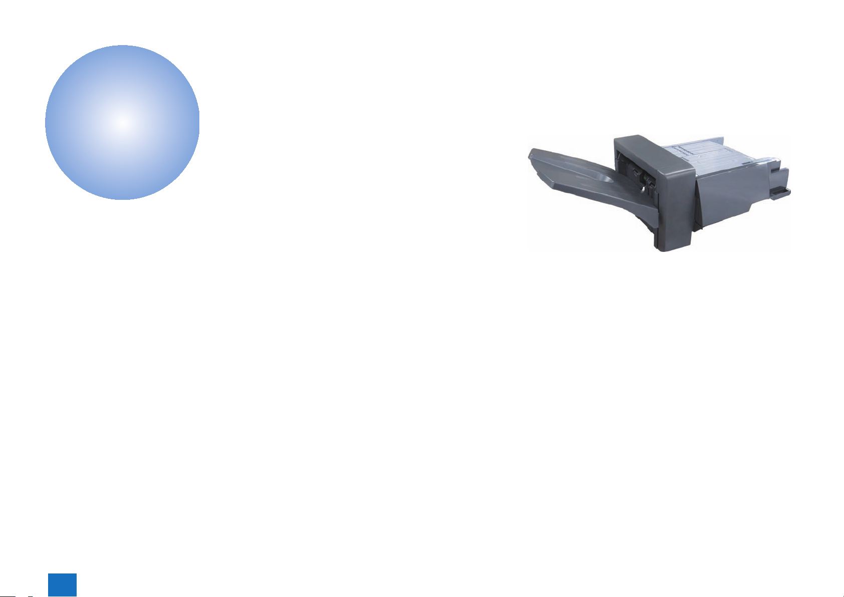
Product Outline
1
Features
■
Specications
■
Names of Parts
■
Product Outline
1

1
Product Outline > Features
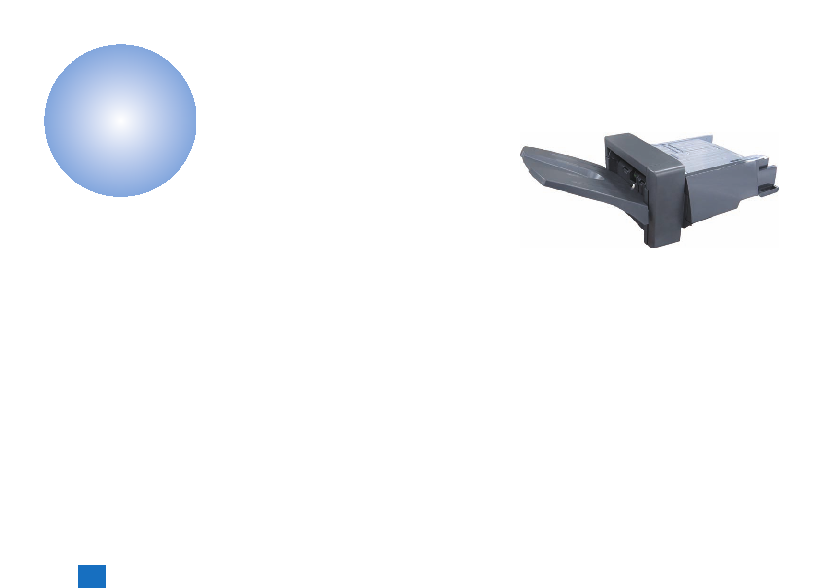
Features
• Compact, staple nisher which corresponds to A4 color, high-speed MFP.
• Gripper mechanism for delivering paper to the stack tray. And the paper stacking of the
high consistency is possible by the mechanism.
• Stack tray capacity of approximate 500 sheets.
• Easy to install on the host machine.
1-2
Product Outline > Features
1
1-2
1
Product Outline > Specications
1-3
Specications
●Finisher Unit
Stacking method Stack tray: moving up and down
Stacking orientation Face down
Stacking paper size Feed direction: 148 to 356 mm
Alignment stacking
paper size
Paper weight 60 to 220 g/m2
Stacking capacity - Processing tray
Mixed stacking
capacity
Dimensions 301 mm (H) × 589 mm (W)× 459 mm (D)
Weight Approx. 14 kg
Power supply From host machine: 24V, 5V
Power consumption Standby: 2.5 W or less
Item Specications Remarks
Cross feed direction: 98 to 216 mm
[Non sort]
Cross feed direction: 98 to 216 mm
[Sort]
Cross feed direction: 139 to 216 mm
[Staple sort]
Cross feed direction: 182 to 216 mm
[Non sort / sort]
6 sheets or less
[Staple sort]
30 sheets or less
- Stack tray
[Non sort / sort]
73.5 mm or less in height (equivalent of 500 sheets)
[Staple sort]
73.5 mm or less in height, or 20 sets or less
[Non sort / sort]
73.5 mm or less in height
[Staple sort]
73.5 mm or less in height, or 20 sets or less
Operating: 35 W or less
- Equivalent of 81 g/m2
paper
- Equivalent of 81 g/m2
paper
T-1-1
●Staple Unit
Stapling method Punching by rotating cam - Flat clinch
Stapling capacity 30 sheets
Stapling paper size A4R, B5R, LGL, LTRR, EXECR, 16KR
Staple supply Special staple cartridge (5000 staples)
Staple detection Provided
Manual stapling Not provided
Initial feed of staple
head
* To set the maximum number of sheets to be stapled in the Finisher. When 1 is set, the
stapling capacity becomes 50 sheets. COPIER > OPTION > USER > STPL-MAX
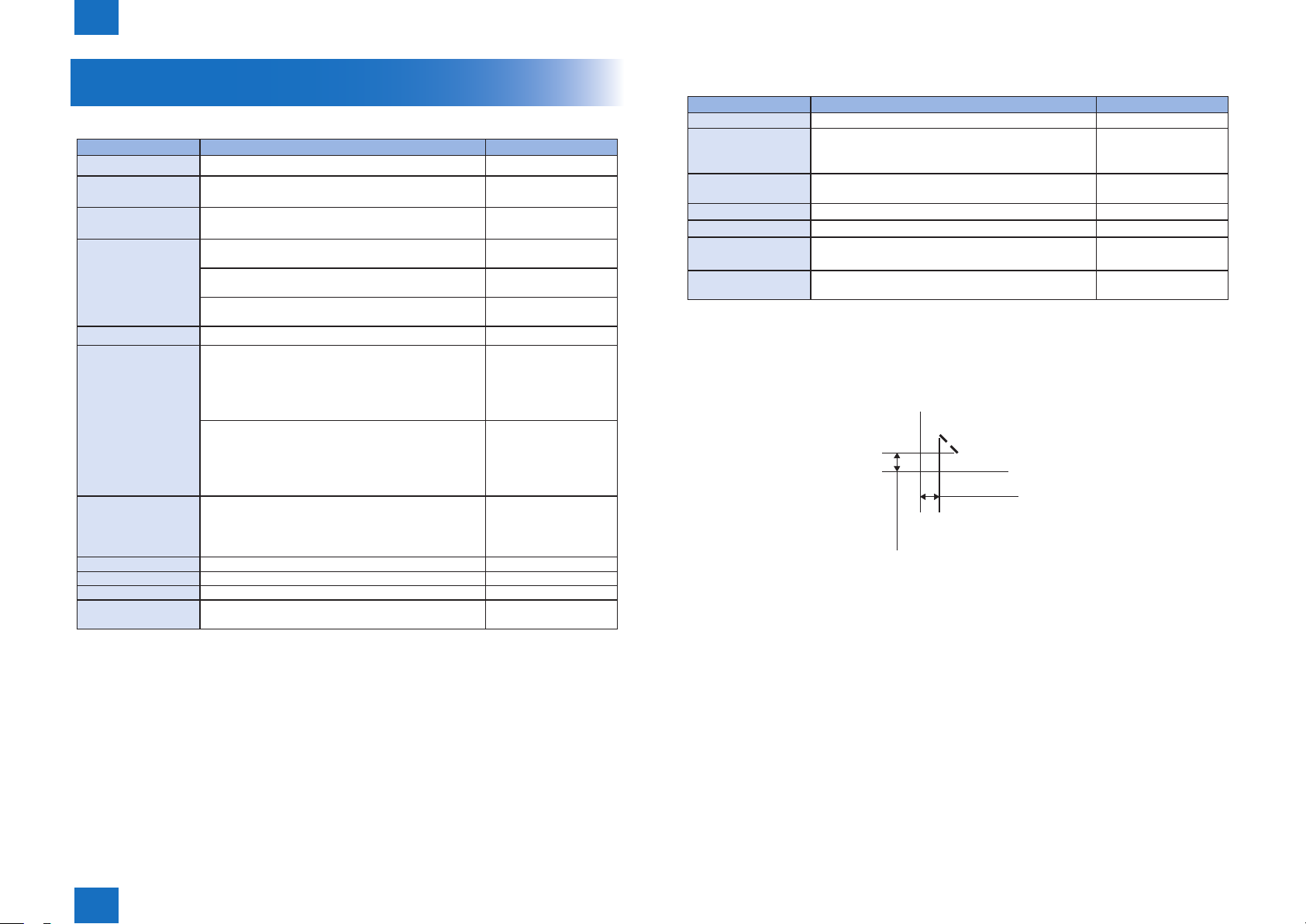
• Staple Position
Item Specications Remarks
Paper thickness: 5.7 mm or less
*
Provided
Front 1-point stapling (45 degrees)
5.0 ± 2.0 mm
5.0 ± 2.0 mm
F-1-1
- Equivalent of 105 g/
m2 paper
T-1-2
Product Outline > Specications
1
1-3
1
Product Outline > Names of Parts > Cross Section
1-4
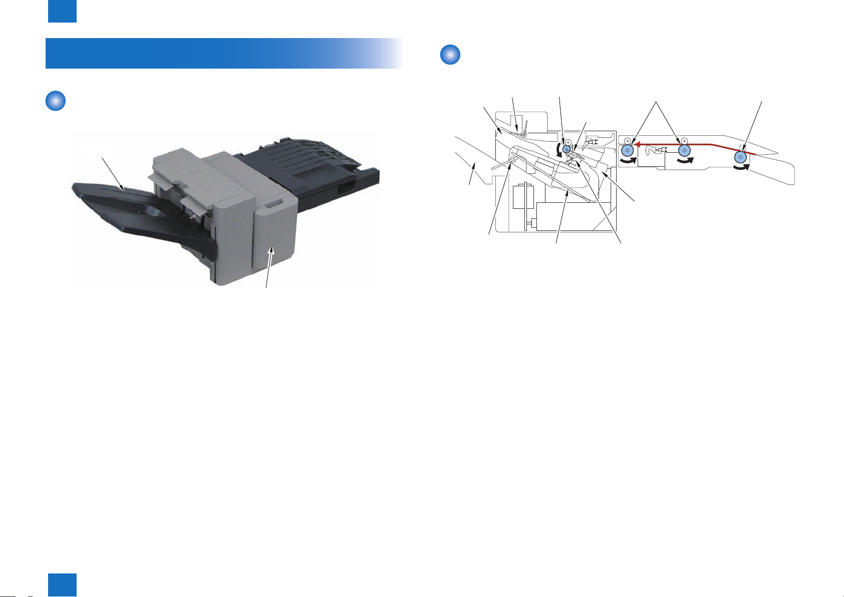
Names of Parts
External View
Stack Tray
Front Door
F-1-2
Cross Section
PaddleAlignment
Plate
Stack Tray
Stack Tray
Paper Retainer
Delivery Roller
Paper Return
Inlet RollerFeed Roller
Paddle
Stapler
GripperTray Auxiliary Guide
F-1-3
Product Outline > Names of Parts > Cross Section
1
1-4
Technology
2
Basic Conguration
■
Controls
■
Basic Operation
■
Feed Unit
■
Processing Tray Unit
■
Stack Tray Unit
■
Controller Unit
■
Detecting Jams
■
Power Supply
■
Work of Service
■
2
Technology
2
Technology > Basic Conguration > Overview of Electrical Circuitry
2-2
Basic Conguration
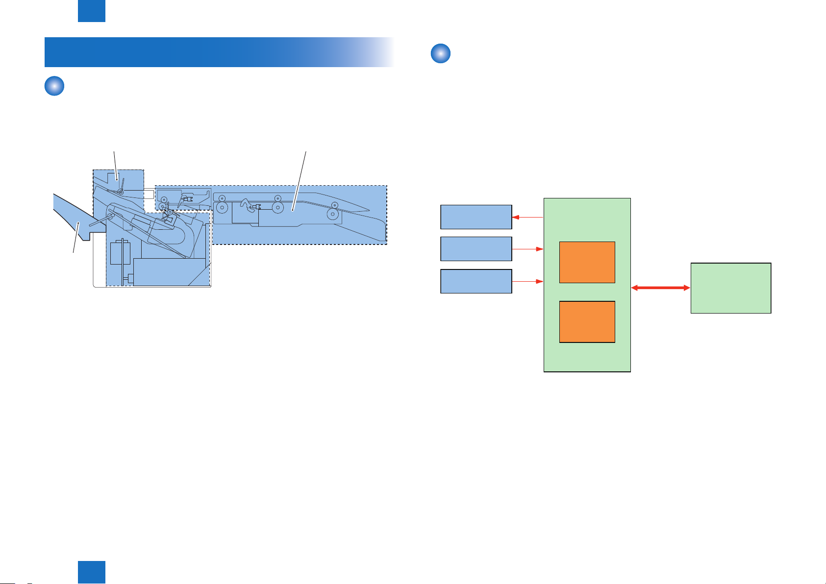
Functional Conguration
The components of this nisher are organized into 3 major blocks; feed unit, processing tray
unit and stack tray unit.
Feed AssemblyProcessing Tray Assembly
Stack Tray
Assembly
F-2-1
Overview of Electrical Circuitry
The nisher's sequence of the operation is controlled by its nisher controller PCB.
The nisher controller PCB has the 16-bit CPU, and the controller also controls the
communication with the host machine in addition to controlling the nisher's operation
sequence.
The CPU on the nisher controller PCB contains a ash ROM used to store the operating
sequence program.
The nisher controller PCB uses the serial communication line to receive various commands
from its host to drive the motors. It also uses serial communications to send information on
the sensors and switches to its host.
Motor
Sensor
Switch
Finisher Controller PCB
CPU
Motor
Driver
Serial
Communication
Host Machine
(DC Controller PCB)
Technology > Basic Conguration > Overview of Electrical Circuitry
2
F-2-2
2-2

2
Technology > Controls > Controls
Controls
Controls
Basic Operation Outline
Feed Unit Outline
Feeding Paper to Processing Tray Unit
Processing Tray Unit Outline
Stacking Operation
Tray Auxiliary Guide Operation
Alignment / Shifting Operation
Staple Operation
Stack Delivery Operation
Stack Tray Paper Retainer Operation
Stack Tray Unit Stack Tray Shift Operation
Stack Tray Paper Height Detection Control
Stack Tray Paper Full Detection Control
Controller Unit Outline
Detecting Jams Outline
Power Supply Outline
Protective Functions
Work of Service When replacing the parts
Periodical Servicing
Upgrading
2-3
Items
T-2-1
Technology > Controls > Controls
2
2-3
2
Technology > Basic Operation > Outline
2-4
Basic Operation
Outline
Basic operations of this nisher are described below.
(1) The paper delivered from the host machine is fed by the inlet roller, feed roller, and
delivery roller.
Plate
PaddleAlignment
Stack Tray
Stack Tray
Paper Retainer
Delivery Roller
Paper Return
Inlet RollerFeed Roller
Paddle
Stapler
GripperTray Auxiliary Guide
F-2-3
Paddle
Paper Return Paddle
Tray
Auxiliary
Guide
(3) The alignment plates are used to align paper in the width direction. (In the illustration
below, paper is aligned with reference to the central reference position.)
Rear Alignment Plate
F-2-4
(2) The paper delivered by the delivery roller is stacked on the processing tray by the
paddle. A paddle and a paper return paddle are used to align paper in the feed direction.
If two or more sheets with a length of 150 mm or more are stacked, the tray auxiliary
guides slide out.
Technology > Basic Operation > Outline
2
Front Alignment Plate
F-2-5
(4) The operations described in (1) to (3) are repeated for each sheet to be stacked on the
processing tray.
2-4
2
Gripper
Technology > Basic Operation > Outline
(5) The stacked sheets are stapled (only in the staple mode).
Stapler
F-2-6
(6) After being shifted, the sheets stacked on the processing tray are delivered to the stack
tray.
If the tray auxiliary guides have slid out, they slide back before the sheets are delivered
to the stack tray.
2-5
Technology > Basic Operation > Outline
2
F-2-7
2-5
2
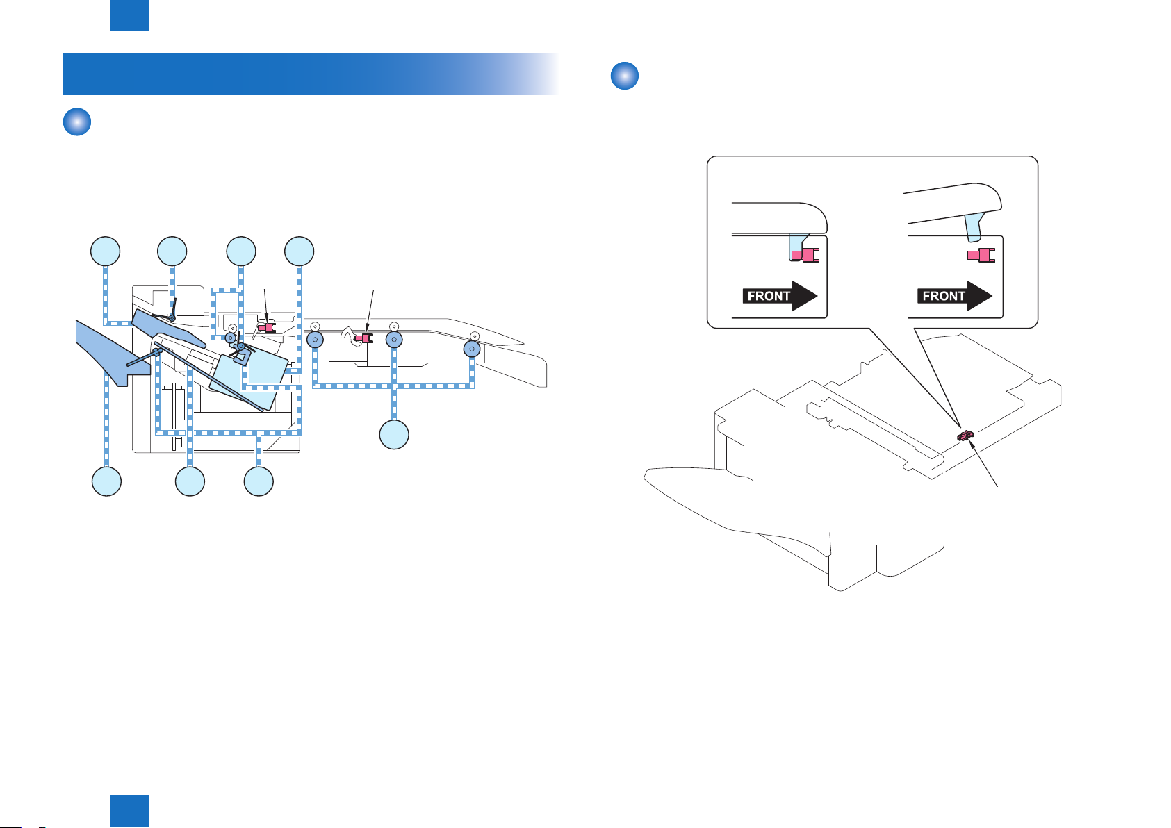
Technology > Feed Unit > Buffer Path Cover Open/Close Detection
2-6
Feed Unit
Outline
The feed unit feeds the paper delivered from the host machine and feeds it to the processing
tray unit.
Two sensors, an inlet sensor (S1) and a delivery sensor (S2), are provided along the paper
feed path in the feed unit to detect the paper feed state and jam.
S2
M9
S1
M1
M4,5
M2M3
Buffer Path Cover Open/Close Detection
The Buffer Path Cover Open/Close Sensor (S16) detects whether the Buffer Path Cover is
open or closed.
<Sensor:ON> <Sensor:OFF>
M8
M1 Feed Motor M7 Gripper Motor
M2 Delivery Motor M8 Stack Tray Shift Motor
M3 Paddle Motor M9 Staple Motor
M4 Front Alignment Motor S1 Buffer Sensor
M5 Rear Alignment Motor S2 Feed Path Sensor
M6 Tray Auxiliary Guide Motor
M6
Technology > Feed Unit > Buffer Path Cover Open/Close Detection
M7
2
F-2-8
Buffer Path
Cover Open/Close Sensor
(S16)
F-2-9
2-6
2
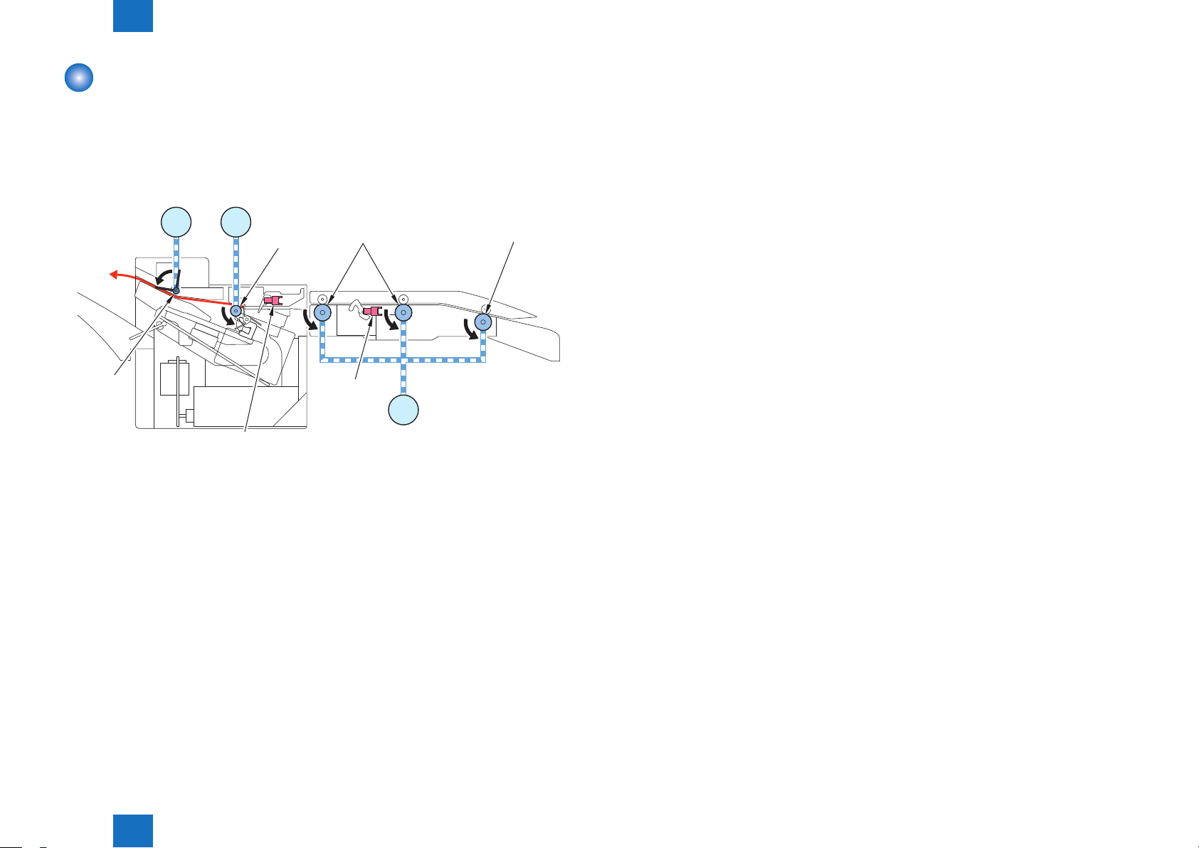
Technology > Feed Unit > Feeding Paper to Processing Tray Unit
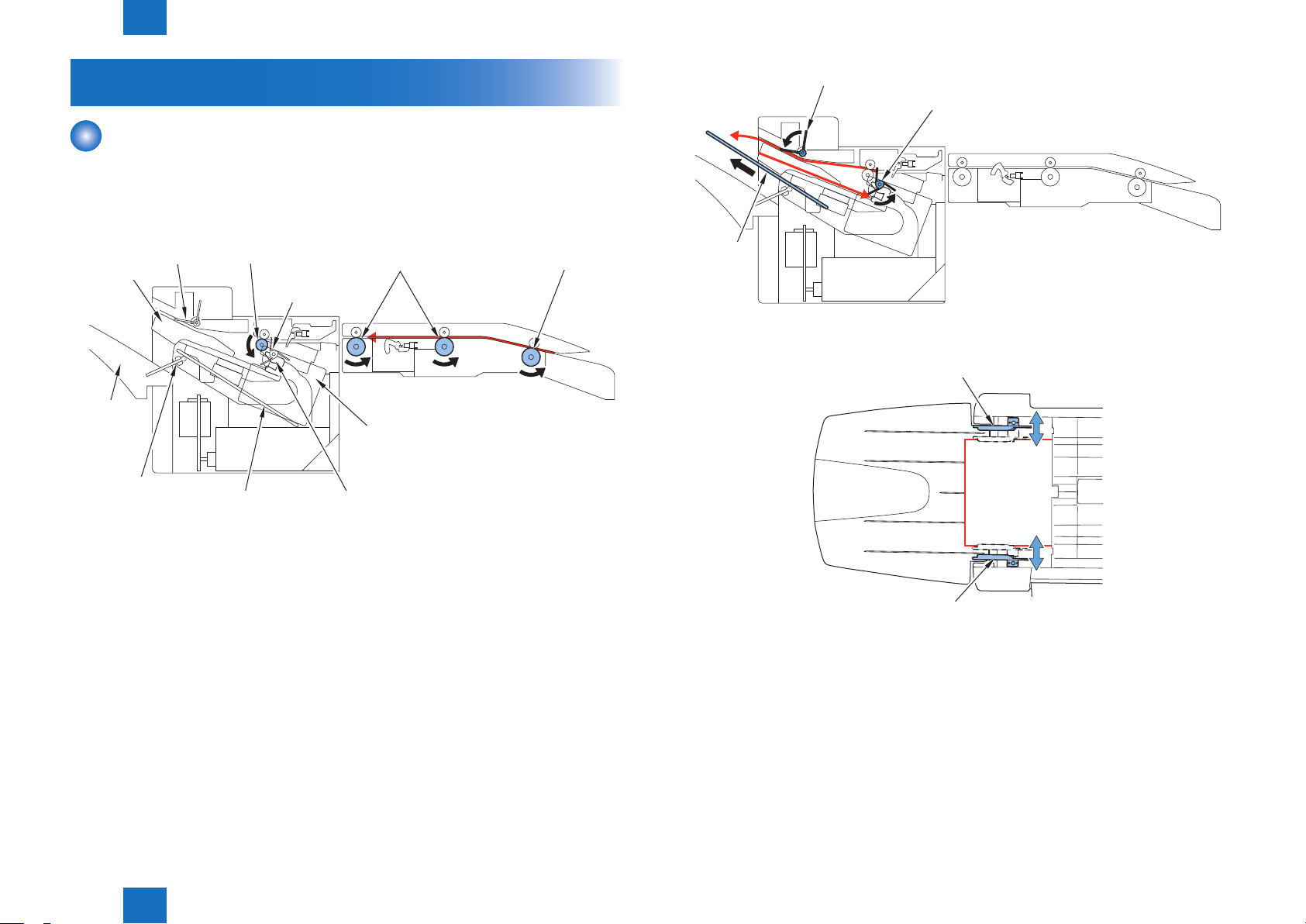
Feeding Paper to Processing Tray Unit
The paper delivered from the host machine is fed by the inlet roller, feed roller, and delivery
roller.
The paper delivered by the delivery roller is stacked on the processing tray by the paddle.
2-7
Paddle
Paddle
Motor
Feed Path Sensor
Delivery
Motor
M2M3
(S2)
Delivery
Roller
Buffer
Sensor
(S1)
M1
Inlet RollerFeed Roller
Feed Motor
F-2-10
Technology > Feed Unit > Feeding Paper to Processing Tray Unit
2
2-7
2
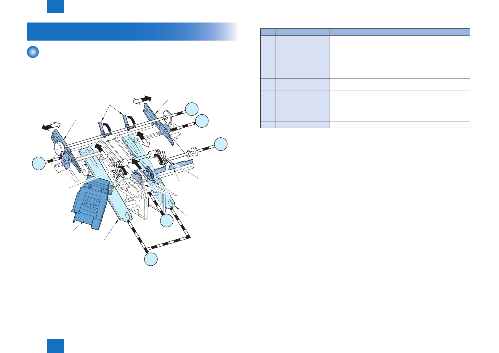
Technology > Processing Tray Unit > Outline
2-8
Processing Tray Unit
Outline
The processing tray unit aligns, shifts, and staples the delivered paper, and then delivers the
paper onto the stack tray using a gripper.
Names and roles of the components of the processing tray are as follows:
Paddle
Front Alignment Plate
M4
Front Alignment
Motor
Paper Return
Paddle
Rear Alignment Plate
M3
Rear Alignment
Motor
Stopper
Paper Return
Paddle
Gripper
Paddle
Motor
M5
M2
Delivery
Motor
No. Name Function
[1] Paddle Stacks the paper delivered from the delivery roller on the
processing tray.
[2] Paper Return Paddle Presses the paper stacked on the processing tray against
the stopper (alignment in the feed direction) and prevents the
previously stacked paper from being fed/delivered.
[3] Front / Rear Alignment
Plate
[4] Gripper Grips the paper stack on the processing tray, and then delivers it
[5] Tray Auxiliary Guide When two or more sheets with a length of 150 mm or more are
[6] Stopper Allows the paper stacked on the processing tray to be pressed
[7] Stapler Staples sheets of paper.
Aligns the paper stacked on the processing tray in the width
direction and shifts the paper.
to the stack tray.
stacked on the processing tray unit, prevents misalignment of
paper due to curl.
against itself to align the paper in the feed direction.
T-2-2
Stapler
Tray Auxiliary Guide
Technology > Processing Tray Unit > Outline
2
M7
Gripper Motor
M6
Tray Auxiliary Guide Motor
Tray Auxiliary Guide
F-2-11
2-8
2
Tray
Technology > Processing Tray Unit > Stacking Operation
2-9
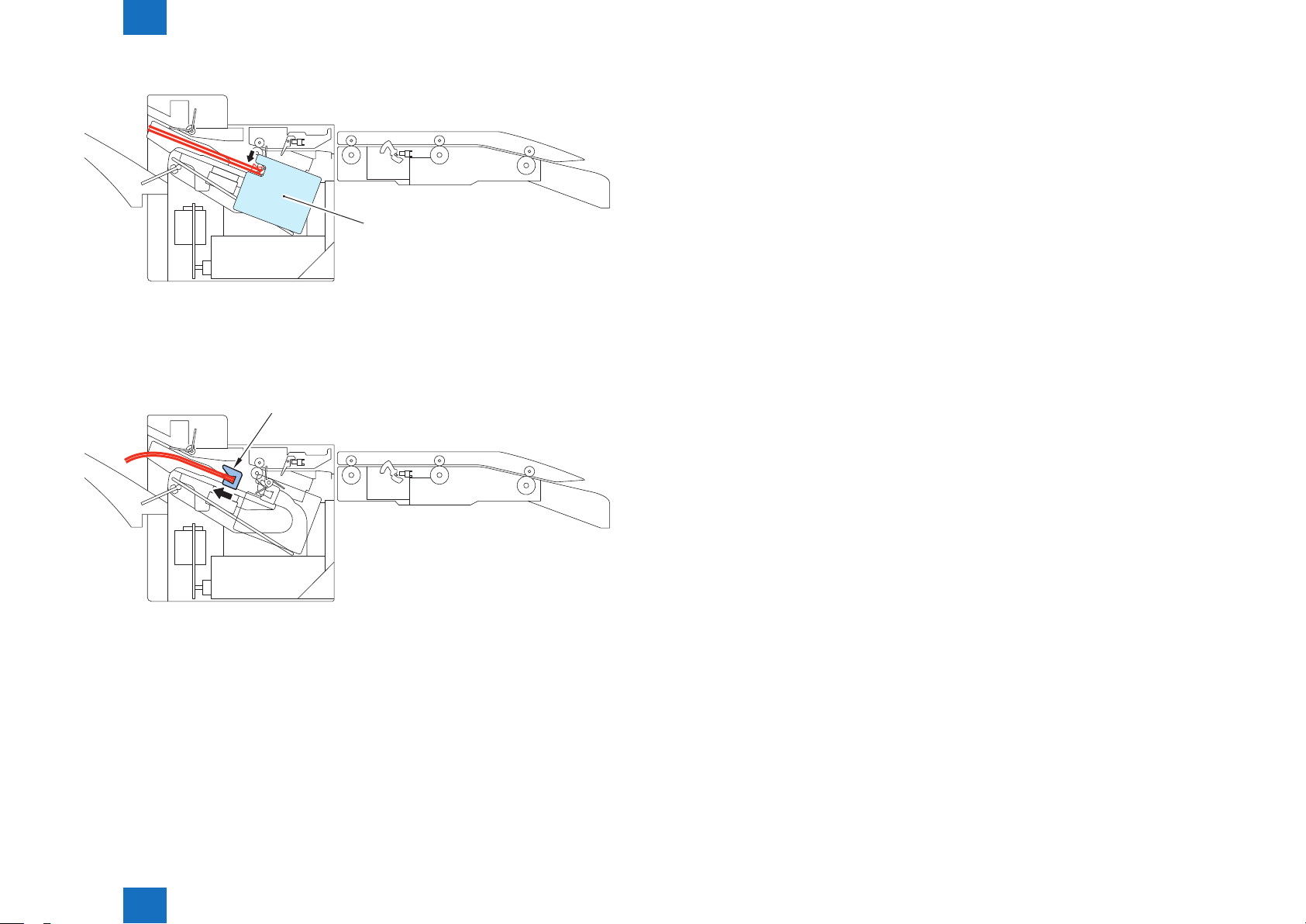
Stacking Operation
The paper delivered from the delivery roller is stacked on the processing tray and the paper is
aligned in the feed direction.
How paper is delivered from the delivery roller and stacked on the processing tray is
described below.
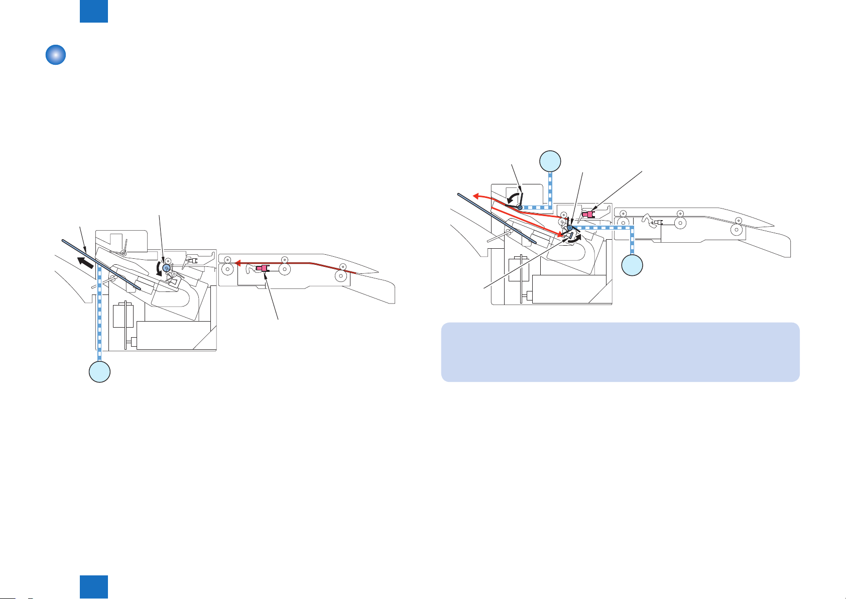
(1) When two or more sheets with a length of 150 mm or more are stacked, the tray
auxiliary guide motor (M6) operates after lapse of the specied time since detection of
paper by the Buffer Sensor (S1), thus sliding out the tray auxiliary guides.
Auxiliary
Guide
Delivery Roller
Buffer Sensor
(S1)
(2) After the specied time has lapsed since paper has passed through the Feed Path
Sensor (S2), the paddle motor (M3) operates to rotate the paddle once to stack the
paper on the processing tray.
The stacked paper is pressed against the stopper by the paper return paddle which is
driven by the delivery motor (M2), thus aligning the paper in the feed direction.
Paddle
Motor
Paddle
Stopper
NOTE:
M3
Paper
Return
Paddle
Feed Path Sensor
(S2)
Delivery Motor
M2
F-2-13
M6
Tray Auxiliary Guide Motor
Technology > Processing Tray Unit > Stacking Operation
2
When a postcard or a sheet shorter than 150 mm is stacked, the paddle does not
rotate.
F-2-12
2-9
2
Technology > Processing Tray Unit > Stacking Operation
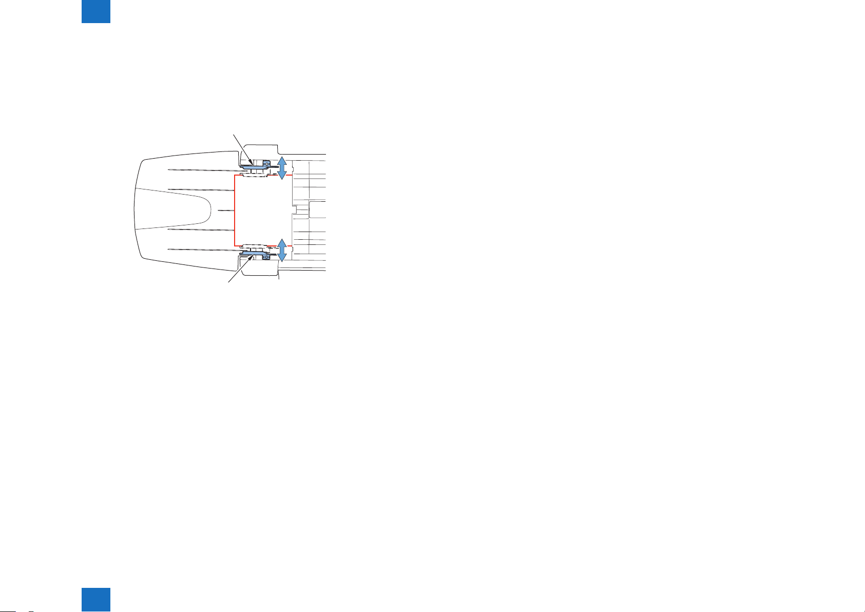
(3) The front and rear alignment motors (M4 and M5) operate to move the front and rear
alignment plates, thus aligning the paper in the width direction. (In the illustration below,
the paper is aligned with reference to the central reference position.)
Operations described in (2) and (3) are repeated for each sheet.
Rear Alignment Plate
Front Alignment Plate
F-2-14
2-10
Technology > Processing Tray Unit > Stacking Operation
2
2-10
2
Technology > Processing Tray Unit > Tray Auxiliary Guide Operation
2-11
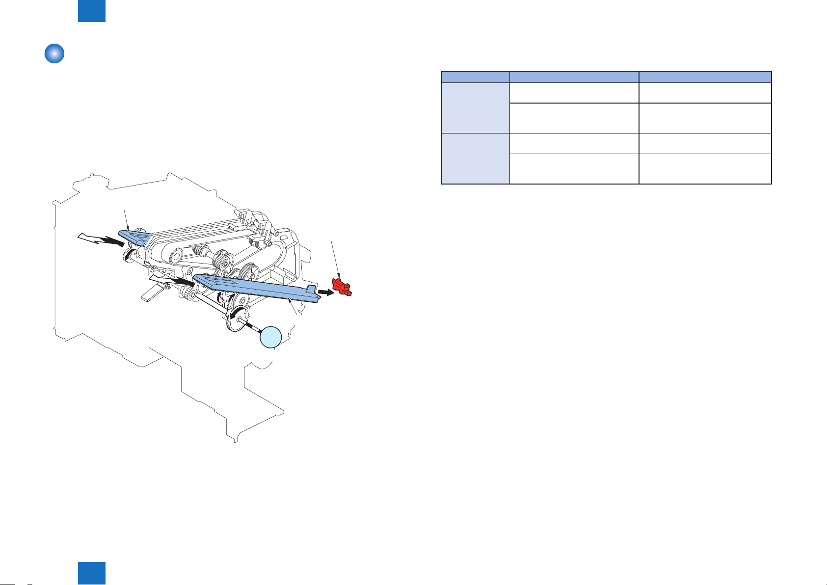
Tray Auxiliary Guide Operation
When two or more sheets with a length of 150 mm or more are stacked on the processing
tray, the tray auxiliary guides slide out to prevent misalignment of paper due to curl.
The tray auxiliary guides are driven by the tray auxiliary guide motor (M6). They slide out
when the inlet Buffer Sensor (S1) detects paper and they slide back when paper is delivered
by the gripper.
The home position of each tray auxiliary guide is detected by the Tray Auxiliary Guide HP
Sensor (S6).
Tray Auxiliary Guide
Tray Auxiliary Guide
HP Sensor (S6)
Tray Auxiliary Guide
The tray auxiliary guide slide-out amount varies depending on the operation mode and paper
length as follows:
Operation Mode Paper Length Amount of Slide Out
Non-Sort / Sort 150 mm or more to less than 217 mm55 mm
217 mm or more to less than 300 mm55 + ("Paper Length" - 216) mm
* The maximum slide-out amount is
120 mm.
Staple 150 mm or more to less than 217 mm55 mm
217 mm or more 55 + ("Paper Length" - 216) mm
* The maximum slide-out amount is
120 mm.
T-2-3
M6
Tray Auxiliary Guide Motor
Technology > Processing Tray Unit > Tray Auxiliary Guide Operation
2
F-2-15
2-11
2
Technology > Processing Tray Unit > Alignment / Shifting Operation
2-12
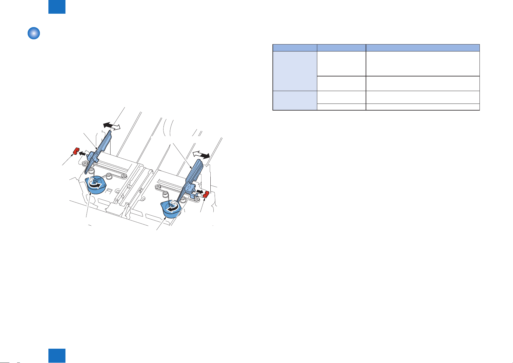
Alignment / Shifting Operation
The paper stacked on the processing tray is aligned in the width direction by the front and
rear alignment plates. Then, the paper is shifted to the position where it is delivered to the
stack tray.
The front alignment plate is driven by the front alignment motor (M4) and the rear alignment
plate is driven by the rear alignment motor (M5). The home positions of the front and rear
alignment plates are detected by the Front Alignment Plate HP Sensor (S4) and Rear
Alignment Plate HP Sensor (S5).
Front Alignment Plate
Rear Alignment Plate
Front Alignment Plate
HP Sensor (S4)
The relationship between operation modes and alignment positions is summarized in the
following table:
Operation Mode Paper Width Alignment Position
Non-Sort / Sort 180 mm or more • Front alignment position: 10 mm frontward from
the central reference position
• Rear alignment position: 10 mm backward from
the central reference position
139 mm or more to
less than 180 mm
Staple 200 mm or more • Top paper: Central reference position
less than 200 mm Stapling position
Central reference position
• Second and subsequent sheets: Stapling position
T-2-4
Front Alignment Motor (M4)
Rear Alignment Motor (M5)
Technology > Processing Tray Unit > Alignment / Shifting Operation
2
Rear Alignment Plate
HP Sensor (S5)
F-2-16
2-12
2
Technology > Processing Tray Unit > Alignment / Shifting Operation
2-13
The relationship between operation modes and shifting positions is summarized in the
following table:
Operation Mode Paper Width Shifting Position
Non-Sort / Sort 210 mm or more • Front shift position: 10 mm frontward from the central
reference position (Same as the alignment position)
• Rear shift position 10 mm backward from the central
reference position (Same as the alignment position)
*: Shift amount: 20 mm
180 mm or more
to less than 210
mm
139 mm or more
to less than 180
mm
Staple 203 mm or more • Front shift position: 10 mm frontward from the central
less than 203 mm Stapling position
NOTE:
• Front shift position: F mm frontward from the central
reference position
F = 110 - ("Paper width" / 2)
• Rear shift position: R mm frontward from the central
reference position
R = 85 - ("Paper width" / 2)
*: Shift amount: 25 mm
• Front shift position: 10 mm frontward from the central
reference position
• Rear shift position: 10 mm backward from the central
reference position
*: Shift amount: 20 mm
reference position
*: Shift amount: 20 mm
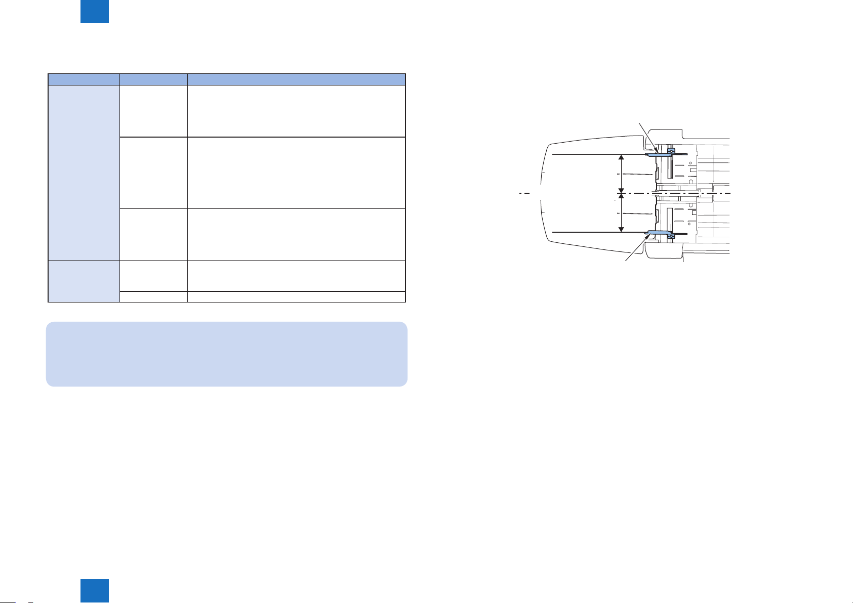
●Alignment Operation in Non-sort / Sort Mode
(1) After lapse of the specied time since detection of paper by the Feed Path Sensor (S2),
the front and rear alignment plates move to the standby position (paper width + 10 mm).
Rear Alignment Plate
Half of Paper Width
+10mm
Middle of Feeding Path
Half of Paper Width
+10mm
Front Alignment Plate
F-2-17
T-2-5
In the non-sort mode, paper is aligned/shifted at the position which is different from the
position where paper was aligned/shifted at the end of the previous copy job.
Technology > Processing Tray Unit > Alignment / Shifting Operation
2
2-13
2
Technology > Processing Tray Unit > Alignment / Shifting Operation
2-14
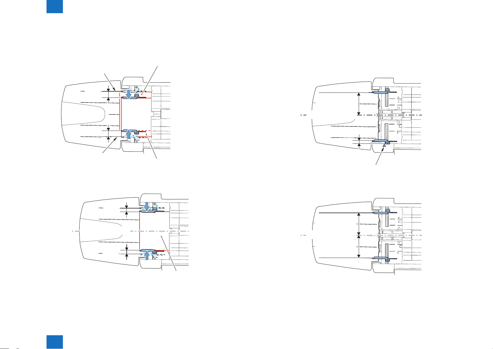
(2) After lapse of the specied time since detection of the trailing edge of paper by the Feed
Path Sensor (S2), the front and rear alignment plates move for paper alignment.
• Front / Rear alignment position (when the paper width is 180 mm or more)
Paper (when aligning in the rear)
Rear Alignment Position
20mm
20mm
Front Alignment Position
Paper (when aligning in the front)
F-2-18
• Alignment position of central reference (when the paper width is less than 180 mm)
●Alignment Operation in Staple Mode
(1) After lapse of the specied time since detection of paper by the Feed Path Sensor (S2),
the front and rear alignment plates move to the standby position (Front alignment plate:
Home position + 2 mm; Rear alignment plate: Paper width + 10 mm).
• Standby position of central reference (when the paper width is 200 mm or more)
Half of Paper Width
+10mm
Middle of Feeding Path
2mm
Front Alignment Plate Home Position
F-2-20
• Front standby position (when the paper width is less than 200 mm)
10mm
Middle of Feeding Path
10mm
Paper
Technology > Processing Tray Unit > Alignment / Shifting Operation
2
F-2-19
Half of Paper Width
+10mm
Middle of Feeding Path
Half of Paper Width
+10mm
F-2-21
2-14

2
Technology > Processing Tray Unit > Alignment / Shifting Operation
2-15
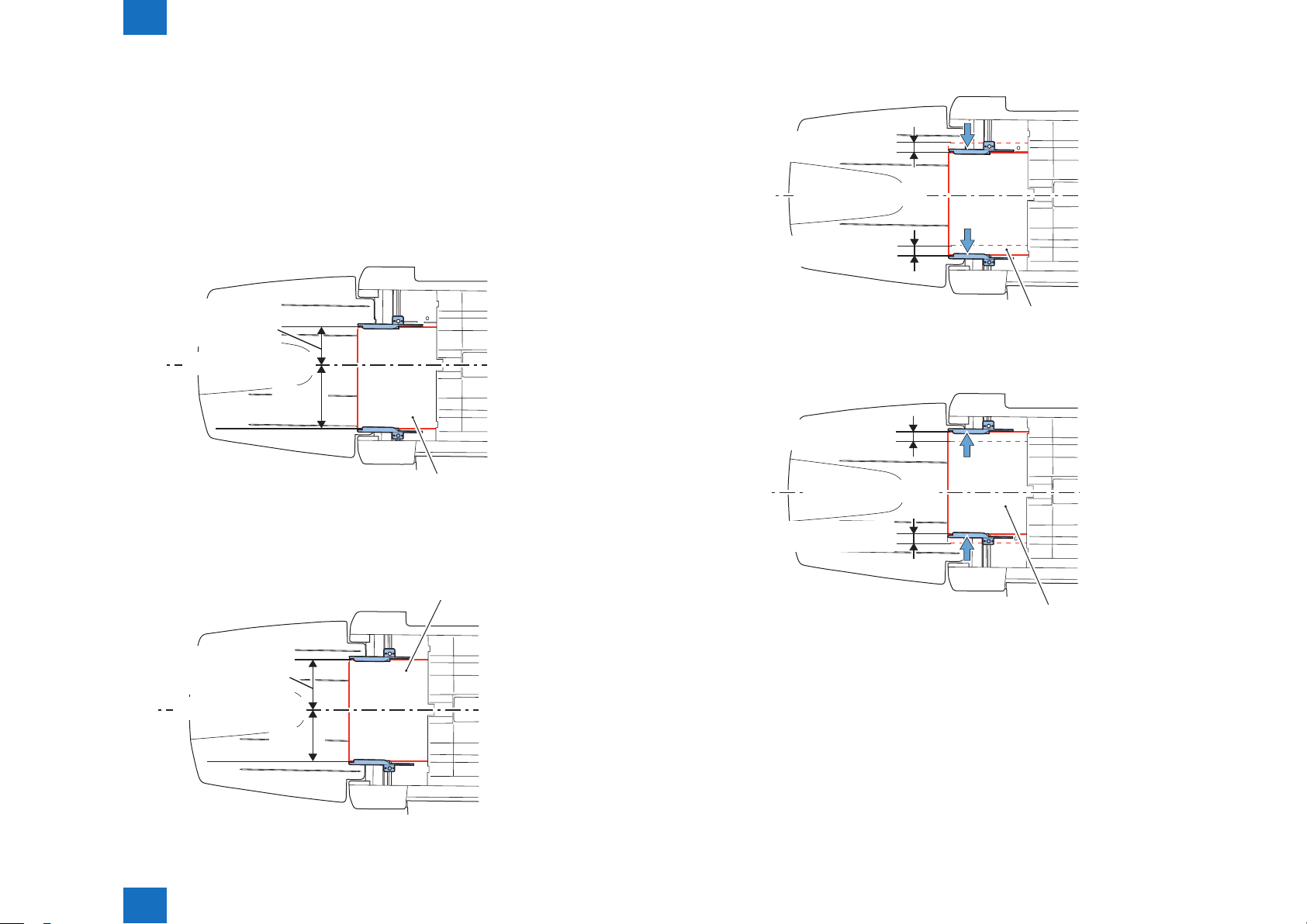
(2) After lapse of the specied time since detection of the paper’s trailing edge by the Feed
Path Sensor (S2), the front and rear alignment plates move to align paper.
• Alignment position of the center reference (in the case of the paper width being 200
mm or more, and top paper)
Half of Paper
Width
Middle of Feeding Path
Half of Paper
Width
Paper
F-2-22
NOTE:
When the paper length is 300 mm or more, alignment of the top paper executed at the
staple position as well.
• Staple alignment position (when the paper width is less than 200 mm)
The position that aligns
paper by the front and
rear alignment plates
+
dmm
2mm
Paper
Front Alignment Plate Home Position
F-2-24
NOTE:
The length d varies by the number of stacking papers on processing tray.
• If the number of sheets stacked is 1 to 3: 2.0 mm
• If the number of sheets stacked is 4 or more: 4.0 mm
• Alignment position of the staple position (in the case of the paper width being 200 mm
or more, and the second and subsequent sheets)
The position that aligns
paper by the front and
rear alignment plates
2mm
Paper
Front Alignment Plate Home Position
F-2-23
Technology > Processing Tray Unit > Alignment / Shifting Operation
2
2-15
2
Technology > Processing Tray Unit > Alignment / Shifting Operation
2-16
●Shifting Operation in Non-sort / Sort Mode
(1) After alignment of the sheet stacked on the processing tray lastly, it is shifted according
to the paper width.
• Front / Rear shift position (when the paper width is 210 mm or more)
The shift position is the same as the alignment position
• Front shift position (when the paper width is from 180 mm or more to less than 210
mm)
The position that aligns
paper by the front and
rear alignment plates
Middle of Feeding Path
110mm
Paper (when aligning in the front)
F-2-25
• Rear shift position (when the paper width is from 180 mm or more to less than 210
mm)
• Front shift position (when the paper width is less than 180 mm)
Alignment position
+10mm front side
Middle of Feeding Path
Alignment position
+10mm front side
Paper (when aligning in the front)
F-2-27
• Rear shift position (when the paper width is less than 180 mm)
Alignment position
+10mm rear side
Middle of Feeding Path
Alignment position
+10mm rear side
Paper (when aligning in the rear)
The position that aligns
paper by the front and
rear alignment plates
Middle of Feeding Path
85mm
Technology > Processing Tray Unit > Alignment / Shifting Operation
2
Paper (when aligning in the rear)
F-2-28
F-2-26
2-16
2
Technology > Processing Tray Unit > Staple Operation
2-17
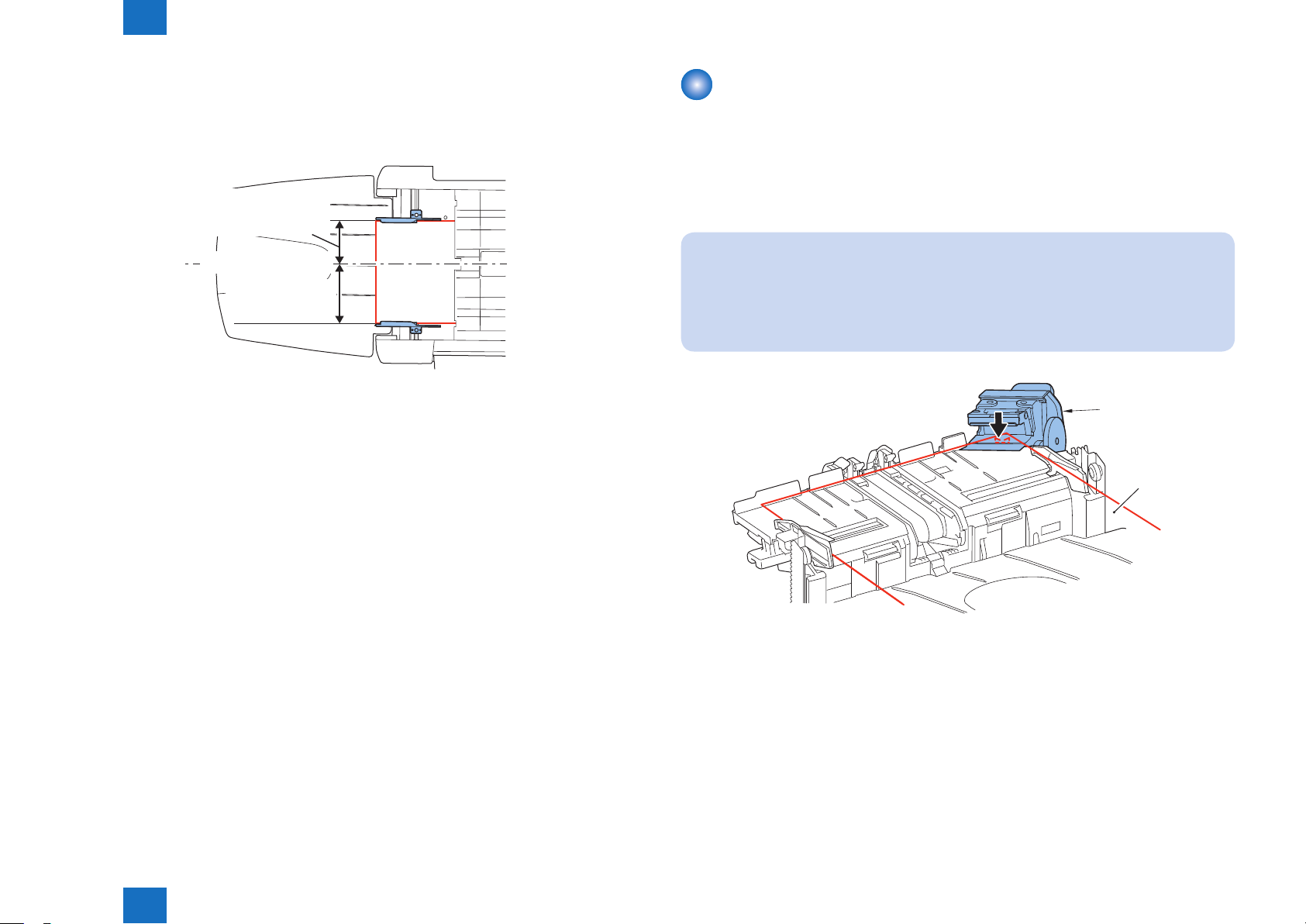
●Shifting Operation in Staple Mode
(1) After completion of stapling, the paper stack is shifted according to the paper width.
• Front shift position (when the paper width is 203 mm or more)
The position that aligns
paper by the front and
rear alignment plates
Middle of Feeding Path
Half of Paper Width
+10mm
F-2-29
• Rear shift position (when the paper width is 203 mm or more)
Shifting position and stapling posion is same.
Staple Operation
When the staple mode is selected, paper is stapled by the stapler after it has been stacked
on the processing tray and aligned.
The stapler is provided at the front of the nisher. Paper is stapled at only one position at the
front.
A maximum of 30* sheets can be stapled.
NOTE:
When the following service mode value set 1, the stapling capacity becomes 50 sheets.
To set the maximum number of sheets to be stapled in the Finisher.
• COPIER > OPTION > USER > STPL-MAX
Stapler
Paper
Technology > Processing Tray Unit > Staple Operation
2
F-2-30
2-17

2
Technology > Processing Tray Unit > Stack Tray Paper Retainer Operation
2-18
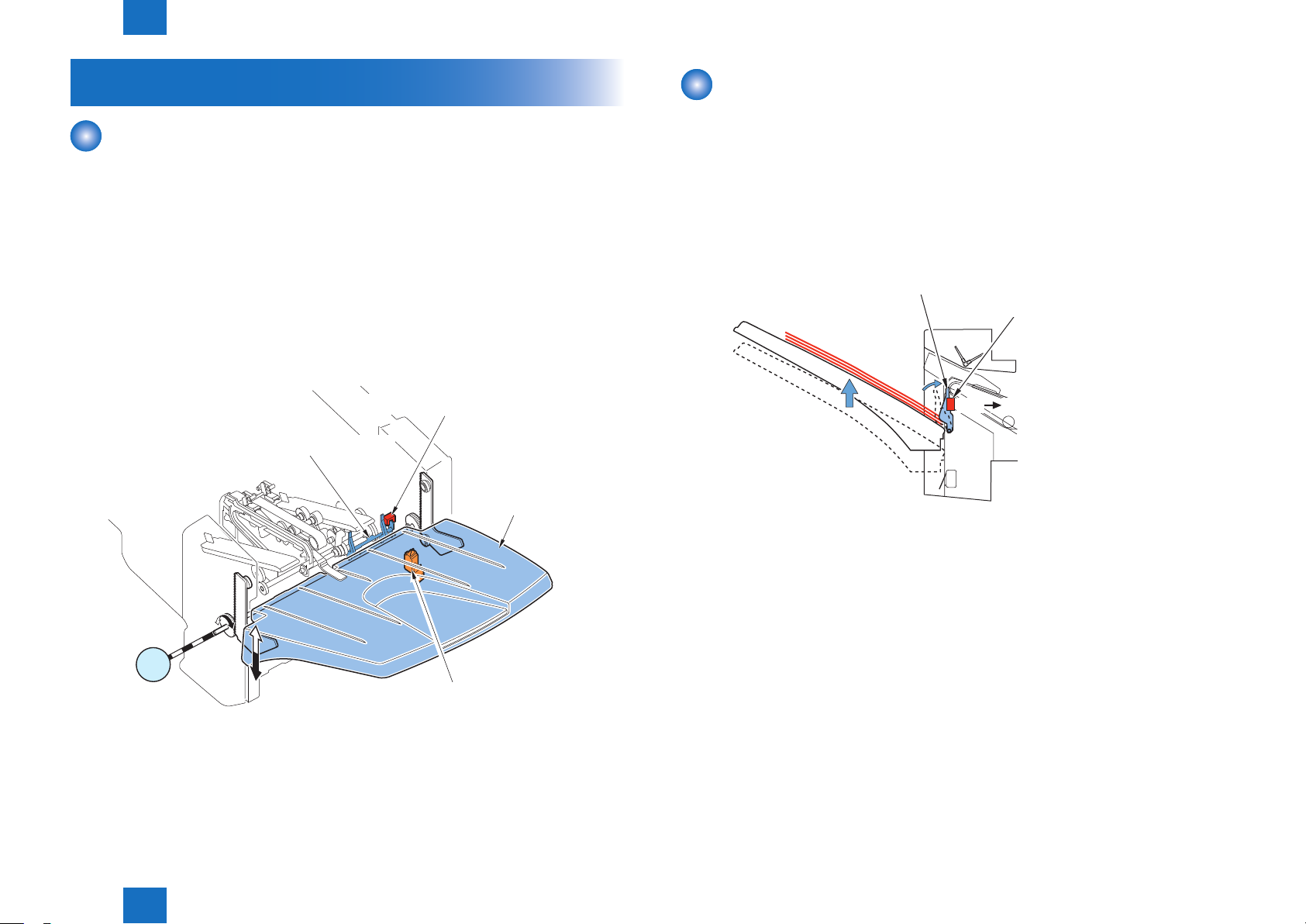
Stack Delivery Operation
The paper stacked on the processing tray is delivered to the stack tray by the gripper after
being shifted and stapled.
The gripper is driven by the gripper motor (M7) via the gripper drive belt.
The home position of the gripper is detected by the gripper HP sensor (S7).
Gripper HP Sensor (S7)
Gripper Drive Belt
Gripper Motor
Gripper
M7
Stack Tray Paper Retainer Operation
The paper delivered to the stack tray is retained by the stack tray paper retainer to prevent
wrong detection of paper height and misalignment caused by curl.
The tray paper retainer is released when the gripper presses portion A of the gear stopper
after it has delivered paper to the stack tray. Then, it is rotated by the driving force of the
gripper motor (M7).
Gear Stopper
Stack Tray Paper Retainer
M7
Gripper Motor
A
Technology > Processing Tray Unit > Stack Tray Paper Retainer Operation
2
F-2-31
F-2-32
2-18
2
Technology > Stack Tray Unit > Stack Tray Paper Height Detection Control
2-19
Stack Tray Unit
Stack Tray Shift Operation
The paper delivered from the processing tray by the gripper is then stacked on the stack tray.
The stack tray is moved up and down by the stack tray shift motor (M8).
When the power is turned on or before start of printing, the stack tray shift motor (M8) is
driven to move the stack tray up/down to the position where the stack tray paper height
sensor (S9) detects the stack tray top surface.
After the paper has been delivered from the processing tray, the stack tray moves down by
the specied amount. Then, the stack tray moves up until the stack tray paper height sensor
(S9) detects the stack tray top surface (top surface of the stacked paper) with the stack tray
paper height sensor ag.
Stack Tray Paper Height Sensor (S9)
Stack Tray Paper Height Sensor Flag
Stack Tray
Stack Tray Paper Height Detection Control
The height of the paper stack on the stack tray is detected by the stack tray paper height
sensor (S9).
After paper has been delivered to the stack tray, the stack tray moves down by the specied
amount.
Next, the stack tray paper height sensor (S9) turns on (the top surface of the paper on the
stack tray is detected).
The above operations are repeated each time paper is delivered to the stack tray.
Stack Tray Paper Height Sensor Flag
Stack Tray Paper Height Sensor (S9)
OFF ON
F-2-34
M8
Stack Tray Lower Limit Switch (SW2)Stack Tray
Shift Motor
Technology > Stack Tray Unit > Stack Tray Paper Height Detection Control
2
F-2-33
2-19
 Loading...