

COPY
.
Thank you for purchasing a Canon product.
Speedlite Transmitter ST-E2 is a wireless transmit
-
ter which can control up to two Speedlite 550EX
groups set as slaves.
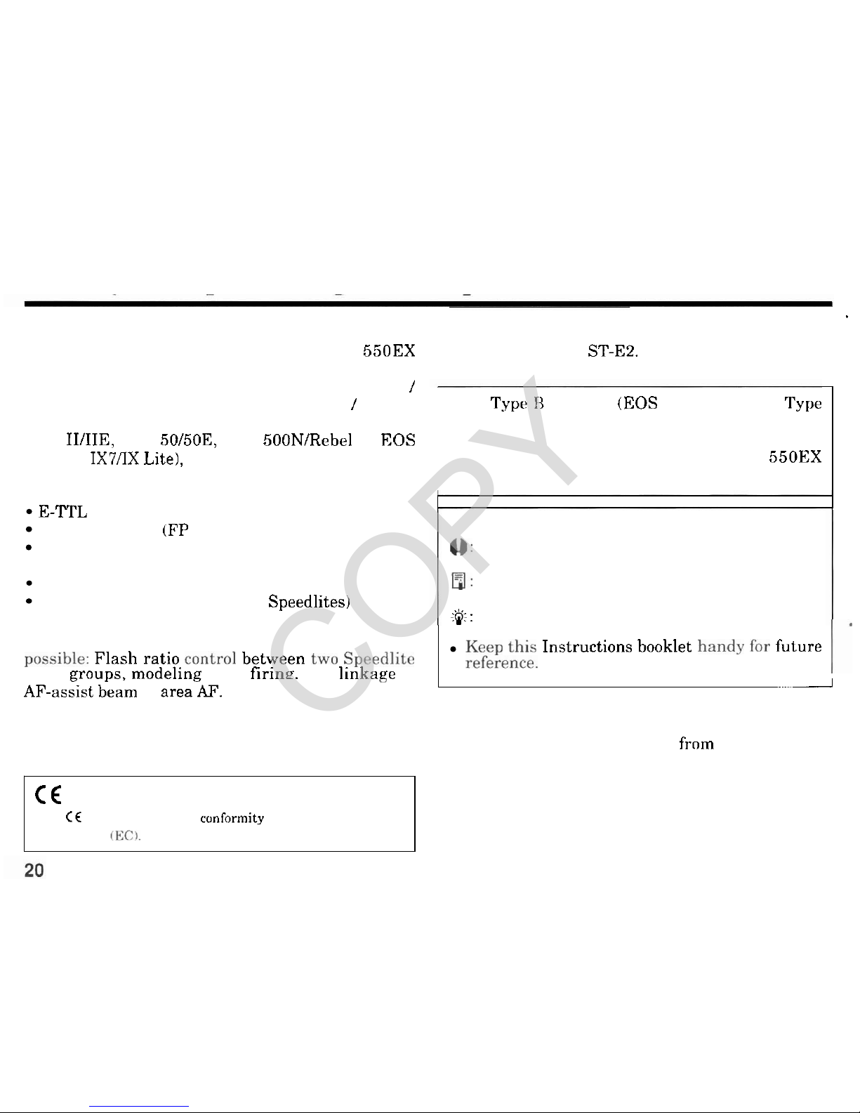
The transmitting range is about 12 to 15 meters
/
39.4 to 49.2 ft indoors and 8 to 10 meters / 26.2 to
32.8 ft outdoors. With Type A cameras (EOS
-
3, EOS
Elan
IIIIIE, EOS 50/50E, EOS 500NlRebel
G,
EOS
IX.
EOS
IX7AX
Lite), the ST-E2 can execute the fol
-
lowing operations through wireless control:
E-?"rL autoflash
High-speed sync (FP flash)
FE lock
Flash exposure compensation
Manual flash (Flash output set with Speedlite)
Multi-flash firing (Set with the Speedlites)
This Instructions booklet assume that a Type A cam
-
'
era is used with the ST-E2.
With Type H cameras (EOS cameras except 'I'ype
A
models), the ST-E2 can be used only for manual
flash and multi
-
flash photography. See pages 23
to 27 in this booklet and the Speedlite
550EX
Instructions.
Symbols used in this Instructions booklet:
0:
Warning for preventing camera or ST-E2
malfunction.
a:
Supplementary notes for using the ST-E2
with the camera.
:'&:
Helpful tip for using the ST-E2 and taking
-
,
AF-askt dea'm to areak.
-
I
I
With the EOS-3, the following operations are also
possible: Flash ratio control between two Speedlite
slave
P~OUDS.
modeline flash firing. and linkage of
C€
The
CE
Mark
is a Directive cunformity
mark
of
the
European
Community
(ECl
pictures.
Keep this Instructions booklet handy for future
reference.
1.
This digital apparatus does not exceed the Class
B
limits for radio noise emissions frnrn digital appara
tus as set out in the interference-causing equipment
standard entitled
"
Digital Apparatus", ICES-003 of
the Industry Canada.
COPY
Contents
1.
Nomenclature
................................................................................................................
22
2.
Readying the ST-E2
.......................................................................................................
23
3.
Readying the
550EX
(Slave Setting)
............................................................................
25
4.
Basic Wireless E-TTL Autoflash Operation
.................................................................
26
5.
Wireless Multi-Flash E-TTL Autoflash Operation
......................................................
29
6.
Applications
...................................................................................................................
33
7.
Troubleshooting
.............................................................................................................
34
Specifications
.......................................................................................................................
.35
Note
All
the operation instructions in this booklet assume that the ST
-
E2 and other relevant equipment are
already turned on. Before proceeding, make sure the
ST-E2
and other equipment are on.
I
I
This device complies with Part
15
of the
FCC
Rules. Operation is subject to the following two conditions:
(1)
This device may not
cause harmful interference, and
(2)
this device must accept any interference receivcd, including interlilrence that may cause
undesired operation.
Do not make any changes or modifications
to
the equipment unless otherwise specified in the instructions. If such
changt.s
or
modifications should be made, you could
be
required to
stop
operation of the equipment.
This equipment has been tested and found to
conlply with the limits for a class B digital device, pursuant
to
part
15
16
the
FCC
Rules. These limits arc designed to provide reasonable protection against harmful interference in a residential installation. This
equipment generates, uses and can radiate radio frequency energy and, if not installed and used in accordance with the
instructions, may cause harmful interference
to
radio communications.
However, there is no
guarantec that interference will not occur in a particular installation. If this equipment does cause harmful
interference
to
radio or television reception, which can be determined by turning the equipment off and on, the user is encour;~g-ed
to try to correct the interference by one or more of the following measures:
Reorient or relocate the receiving antenna.
Increase the separation between the equipment and receiver.
Consult the dealer or an experienced radiolIli technician for help.
21
COPY
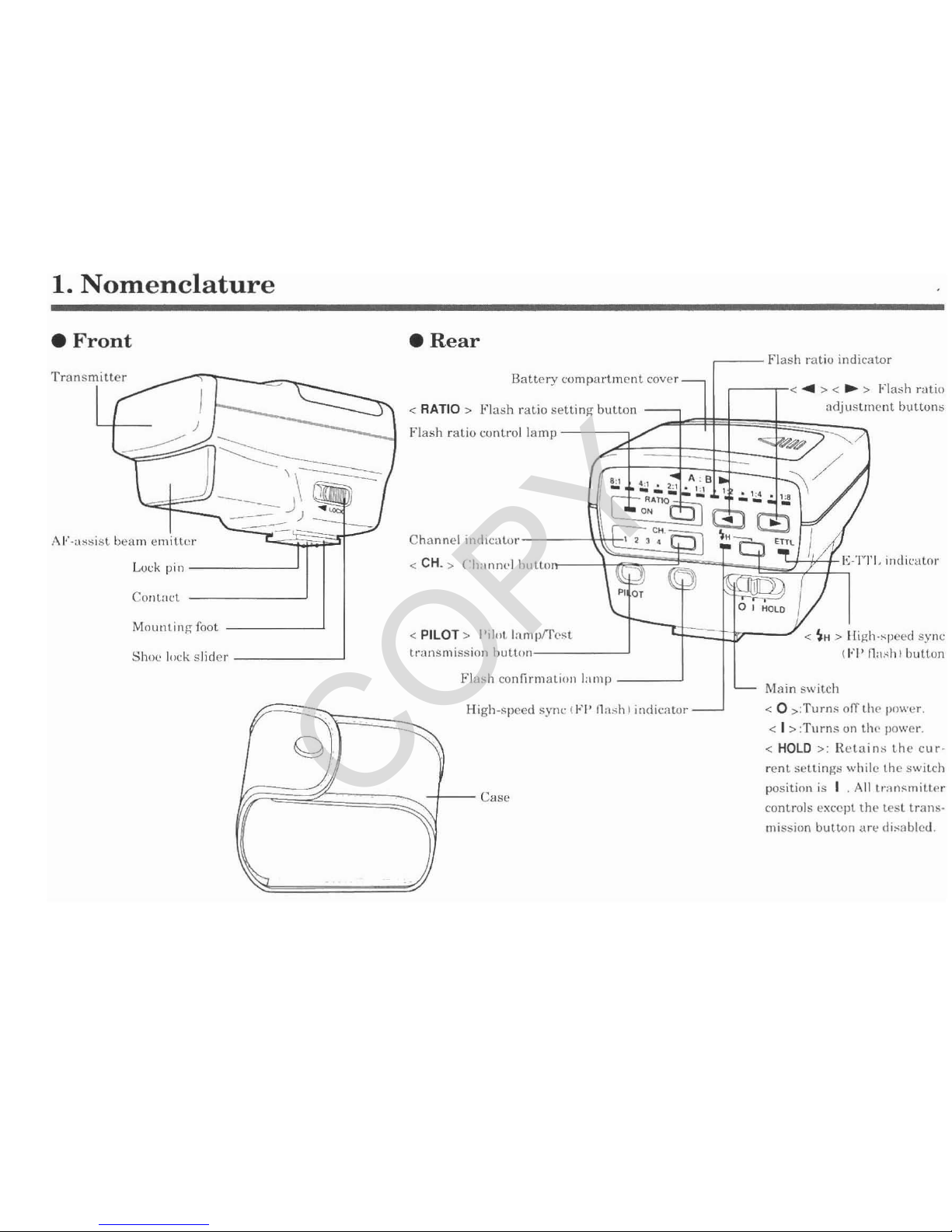
1.
Nomenclature
Front
Rear
Battery compartment cover
Flash ratio
cuntrol lamp
,+I"-assist beam emlttor Channel intl~cat,~r
<
PILOT > I'ilot. I:im
Shoc
lt~k slider trnnsmission button
High-speed synr (FI'
fl:~:
<
0
,:Turns
off
thr 11rnr.er.
<
I
>:Turns on thr po\rer.
<
HOLD
>:
Retains the cur-
rent settings
u,hilo thr switch
position is
I
.
All lr:,nsmiLter
controls except the tPet transmission button
;ire
~lis:$blcd.
COPY
2.
Readying
the
ST-E2
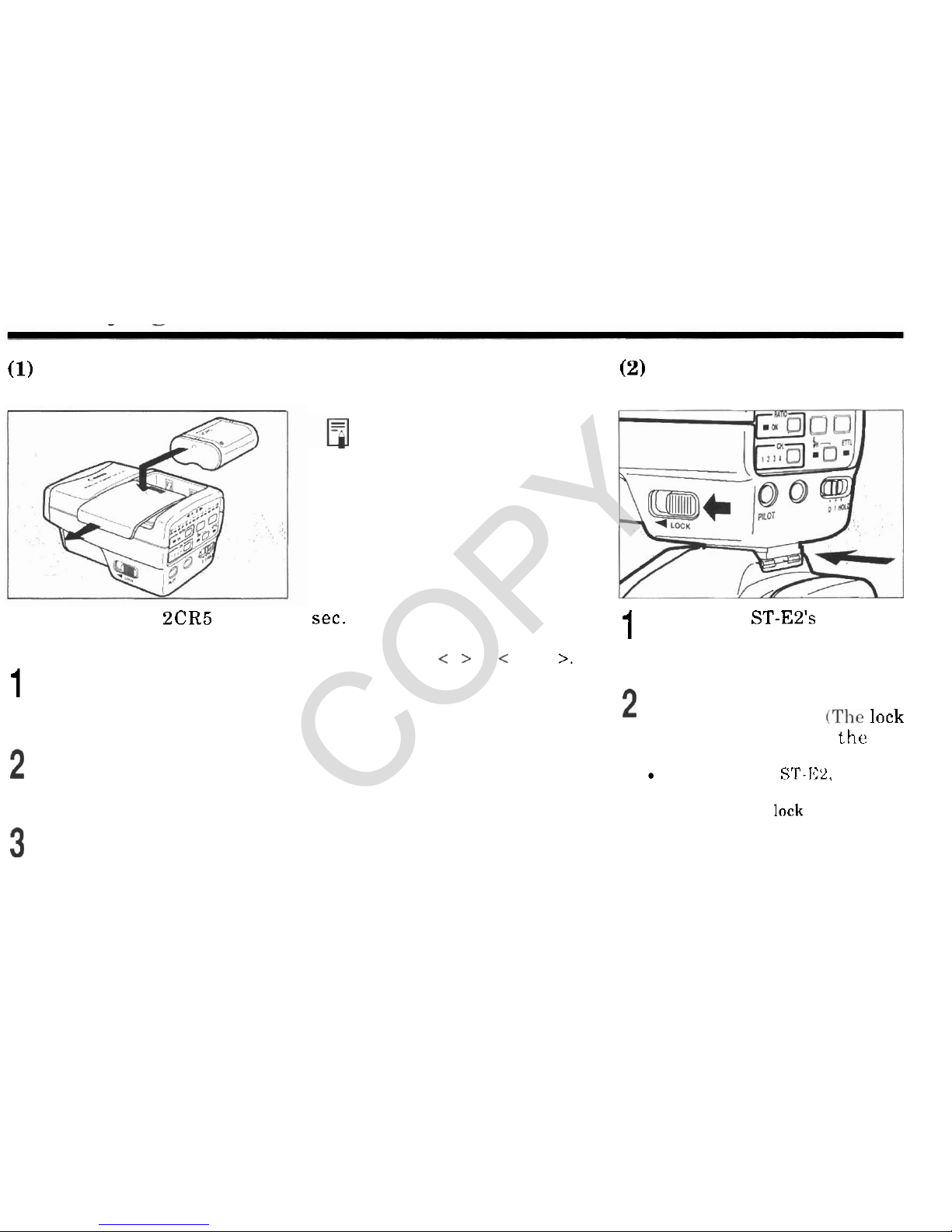
(I)
Installing the Battery
Use one lithium 2CR5 battery
(sold separately).
1
Slide the battery compartment
cover as shown by the arrow
and remove.
Install the battery in the orien
-
tation shown in the compart
-
ment.
Install the battery compart
-
ment cover to close the battery
compartment.
About the battery
If
the battery contacts are
soiled, improper electrical con
tact may result. Before
installing the battery, wipe the
battery contacts with a clean
cloth.
When to replace the battery
Replace the battery if it takes
30
sec. or longer for the red pilot
lamp to light after you set the
main switch to
<
I
>
or
<
HOLD
>.
(2)
Attachment to the
Camera
Push in the ST-E2's mounting
1
foot all the way into the camer
-
a's hot shoe.
Slide the shoe lock slider as
shown by the arrow.
(The lock
pin protrudes to lock
the
ST
-
E2 onto the camera.)
To remove the
ST-152,
slide the
shoe lock slider
in
the opposite
direction (the
lock pin retracts)
and
slide off the
ST-EP.
COPY
Readvine the ST-E2
The hot shoe on the EOS 650,
EOS 620, EOS 750, and EOS
850
will not couple with the
lock pin. The ST-E2 can still be
attached to these cameras, but
it cannot be locked onto the hot
shoe.
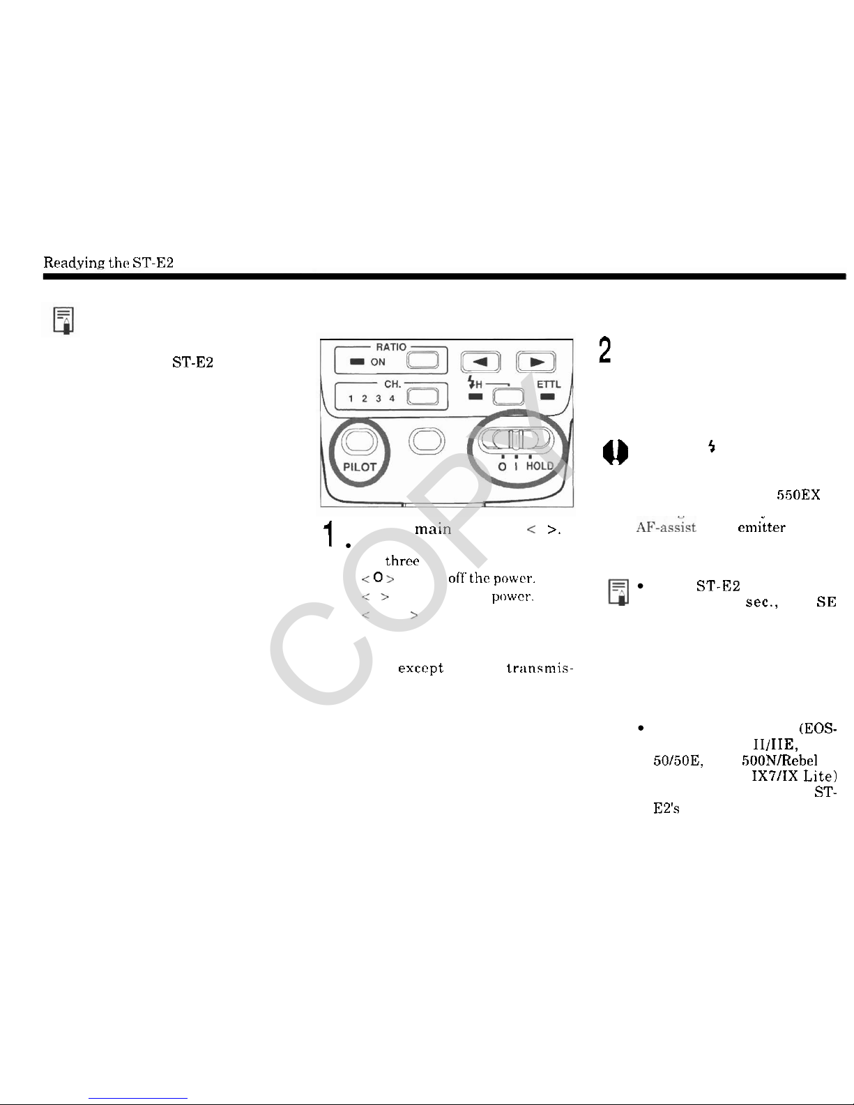
(3)
Turning
On
the
Power
1
Turn the main switch to
<
I
>.
The main switch has the follow
-
ing three positions:
<
0
>
:
Turns of'f'the powcr.
< I >
:
Turns on the powrr.
<
HOLD
>
:
The settings which
were set at the
I
switch position
arc frozen. All transmitter con
trols exccpt the test trtinsmis-
sion button are disabled. This
prevents inadvertant alteration
of
transmitter settings.
When
transmission is possible,
2
the pilot lamp lights
in
red and
the
5
icon lights in the camera
viewfinder.
0
When the 5 icon lights in the
camera viewfinder, it indicates
that the ST
-
E2 is able
to
trans
-
mit. When Speedlite 550EX
is
rechareed and readv to fire. its
AE-assist beam emiiter blinks.
Q
If the ST-E2
is
on and not
used for
90
sec., the SE
(Save Energy) feature takes
effect and turns off the
power automatically to save
battery power. The ST
-
E2
turns back on when the
shutter button or test trans
mission button is pressed.
With a Type A camera (EOS-
3,
EOS Elan IIIIIE, EOS
50/50E, EOS 500NIRebel
G,
EOS IX. EOS IX7IIX Lite)
equipped with E-ITL, the ST-
E2's E-ITL indicator lights.
COPY
 Loading...