

Page 1
Specications
Flash
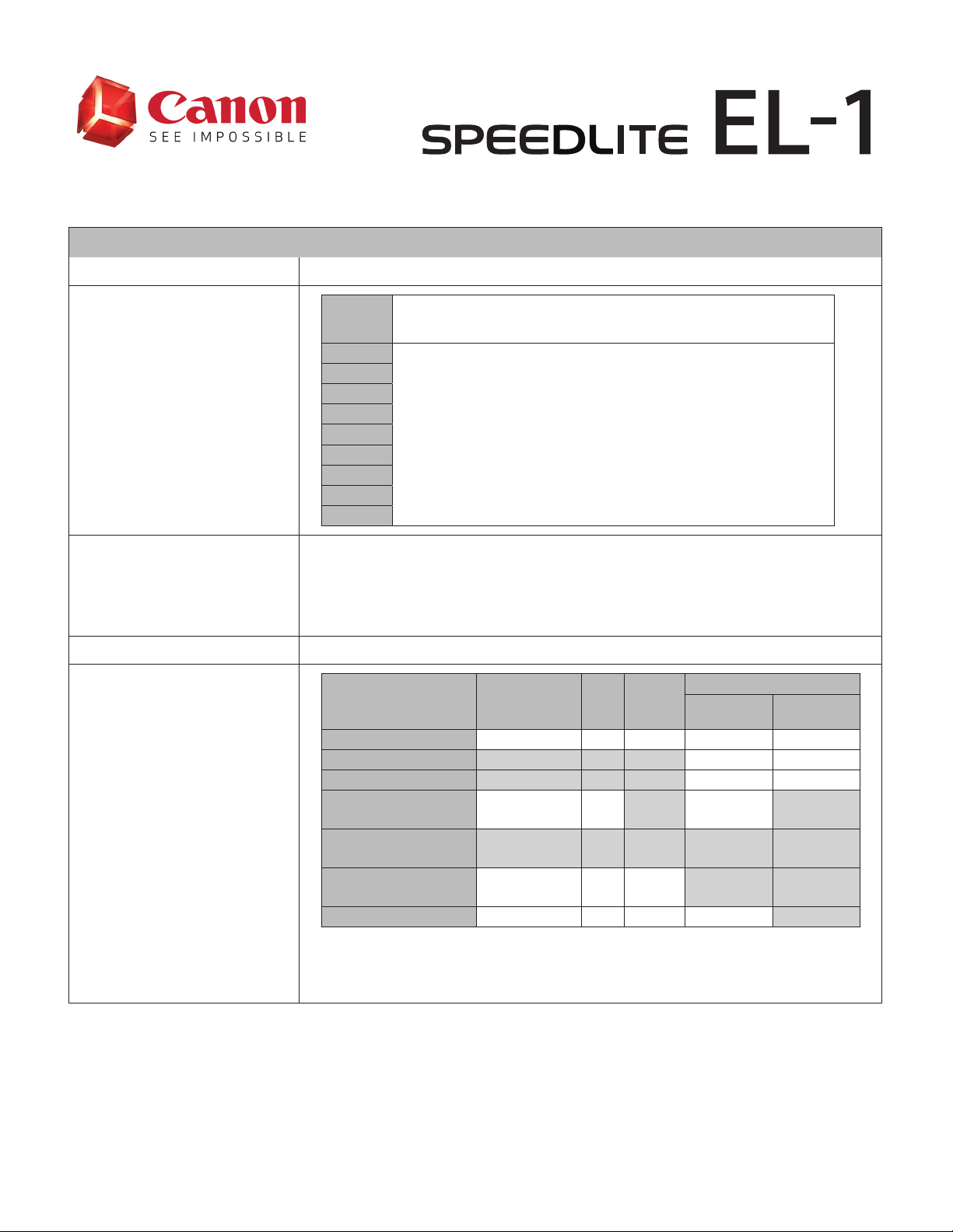
Compatible Cameras Type-A EOS cameras (E-TTL II/E-TTL autoash)
14mm
24mm
28mm
Flash Coverage
(Focal length; for 35mm
full-frame)
35mm
50mm
70mm
80mm
105mm
135mm
200mm
• The Guide No. is approximately 46.3 ft./14m at ISO 100.
-When the extendable wide panel is pulled out, the ash coverage is 14mm.
Guide Number
• The maximum Guide No. is approximately 196.9 ft./60m at ISO 100 and 200mm ash
coverage.
-When the extendable wide panel is pulled out, the ash coverage is 14mm.
Maximum Energy 76 Ws.
E-TTL II/E-TTL autoash*¹ Yes Yes Yes Ye s Yes
Stroboscopic Flash Yes Ye s
Auto Ex ternal Flash
Flash Modes
(Exposure Control Modes)
Manual External Flash
Continuous Shooting
*1: Set automatic ally when the camera shooting mode is set to Basic Zone modes.
*2: Only Group ring is available.
*3: Can only be set when the Speedlite is used as a sender in radio transmission wireless operation.
*4: Only groups set to E-TTL II / E-TTL autoash.
Wide Panel: Manual
* Not compatible with EF15mm f/2.8 Fisheye or EF8 -15mm f/4L Fisheye USM shooting angles of view
Zoom
• A: Auto
Flash coverage is set automatically, accounting for [Auto zoom for sensor size] and
[Light distribution] settings at the lens focal length.
• M: Manual
Flash coverage is set manually
[Auto zoom for sensor size] and [Light distribution] settings are not taken into account.
Radio
Wireless
Optical
Transmission
Flash Mode
Manual Flash Yes Ye s
Metering
Metering
Priority Mode
Group Firing* ³ Yes Yes Yes * ⁴ Ye s
Flash
Exposure
Compensation
Yes Yes Yes * ²
Yes Yes Yes
FEB FE Lock
Transmission
1
Page 2
±3 stops, in 1/3-stop or 1/2-stop*¹ increments.
* The Speedlite's flash exposure compensation takes precedence if flash exposure
Flash Exposure Compensation
compensation is per formed by both the Speedlite and the camera. Users who prefer to
enable flash exposure compensation by the camera should set flash exposure
compensation by the Speedlite to 0.
*1: Corresponds to exposure level increments on the camera.
±3 stops, in 1/3-stop or 1/2-stop*¹ increments.
FEB
* FEB is automatically deactivated after three shots.
* Can be used with flash exposure compensation and FE lock.
*1: Corresponds to exposure level increments on the camera.
FE Lock Supported
Supported
• Stores the flash output of E-TTL II / E-TTL autoflash and automatically sets the stored
output level if users switch the flash mode to manual flash.
* Flash output may vary slightly between E-TTL autoflash and manual flash.
• Colors may vary between E-TTL autoflash and manual flash under the following conditions:\
* When the color temperature of the Speedlite light differs greatly from that of ambient
lighting and flash exposure compensation is set toward the negative end.
* When E-TTL balance is set to [Ambience priority].
FE Memor y
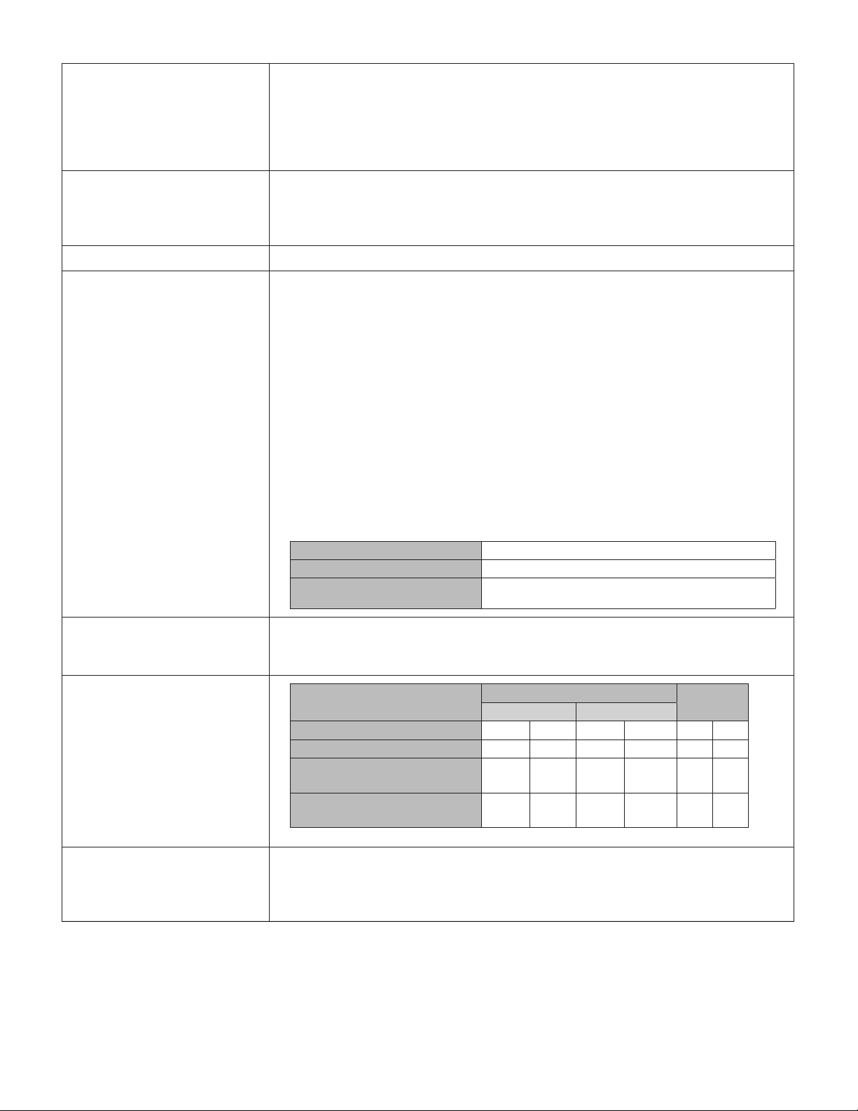
Number of Flashes
Recharge Time
• Differences in colors between E-TTL autoflash and manual flash may be reduced by taking
one of the follow steps:
* Using the provided color filter.
* Setting white balance to an option other than AWB.
Set in P.Fn-05
0: O Disabled
1: On Enabled
2: On / Mode ETTL - M
Enabled/ One- touch switching between E-TTL autoash and
manual ash
Approx. 335–2,345 ashes.
* With a fully charged Battery Pack LP-EL.
* Based on Canon Testing Standards.
Power Supply
Flash Power Min. Max. Min. Max. Min. Max.
Speedlite EL-1 0.1 sec. 0.9 sec. 01. sec. 0.8 sec. 335 2345
Speedlite EL-1
+ CP-E4N (AA /LR6 Alkaline batteries)
Speedlite EL-1
+ CP-E4N (AA /LR6 Ni-MH batteries)
Recharge Time (approx .)
Normal Flash Quick Flash
0.1 sec. 0.6 sec. 01. sec. 0.5 sec. 560 3920
0.1 sec.. 0.4 sec. 01. sec. 0.35 sec. 680 476 0
Flash count
(approx.)
* Based on Canon Testing Standards
Flash Range
Eective ash range with EF 50mm f/1.4 lens at ISO 100 [Light distibution: Standard]
1) Normal Flash: Approx. 1.6–85.6 ft./0.5 –26.1m
2) Quick Flash (Flash-ready lamp: blinking): Approx. 1.6–52.5 ft./0.5–16.0m
3) High-speed Sync (at 1/250 sec. shutter speed): Approx. 1.6– 45.3 ft./0.5–13.8m
2
Page 3
AF Assist Beam
Modeling Lamp
System:
Infrared AF-assist beam
Compatible AF System:TTL second image formation phase-dierence AF
Supporting 1–191 AF points (28mm or longer focal length)
• Phase-dierence AF during viewnder shooting
Eective Range (Approx.):
At center: 2.0–32.8 ft./0.6 –10.0m
At periphery: 2.0 –16.4 ft./0.6–5.0m
Supported
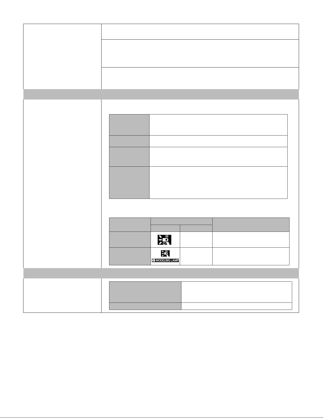
The modeling lamp (LED turns on under the following conditions
Brightness*¹
Color temperatue*¹
On
Modeling Lamp
O
*1: set in P.Fn-08
Higher LED temperatue from prolonged illumination triggers the following safety functions
Temperature in-
crease
Level 1 On
Level 2
Wireless Functions for Radio Transmission
Manual setting: 1 (Low) to 5 (High)
*Default setting: 5 (High)
Manual setting: 1 (Orange) to 5 (White)
*Default setting: 1 (Orange)
Illuminated in response to the following operations
• Pressing the <LAMP> button
• Pressing the shutter button halfway twice (with C.Fn-18 set to 1).
O under the following conditions
• Releasing the shutter button
• Pressing the <LAMP> button
• Pressing the shutter button halfway twice (with C.Fn-18 set to 1)
• Timer: 5 min. / 30 min. / Unlimited (can be changed in P.Fn-09)
LCD Panel
Icon display Illumination
Blinking
(2 Hz)
Modeling Lamp Operation
Modeling lamp brightness is lowered one
level, if at the maximum level
Modeling lamp is turned o
Wireless Settings
Supported
Sender
Receiver Supported
*Secondary and additional units serve as sub- senders and
display a "SUB SENDER" ic on.
* Sub-senders cannot be remotely controlled by a receiver unit
3
Page 4

Communication Functions
Compliance standards IEEE 802.15.4, ARIB STD-T66
Communication method
Transmission frequency 2405 -2475 MHz
Channel
Wireless radio ID
Transmission range*¹*² Approx. 9 8.4 ft. / 30 m
Groups
Number of possible units
for communication
Max. sender units
Max. receiver units Up to 15
*1: Without any obstructions bet ween senders and receivers, and without radio inter ference from other devices.
*2: Transmission range may be shor ter depending on factors such as how units are arranged, the surrounding
environment, and weather conditions.
Primar y modulation: OQ PAK
Secondary modulation: DS-SS
Channel 1-15
Setting: Auto / Manual
0000 to 999 9
Setting: Manual
Up to 5 groups (A-E)
* Sender units are set to Group A
Up to 16 units of senders and receivers in total
Up to 15
* Secondary and additional units serve as sub-senders
Transmission Status Display
Wireless Firing Control
E-TTL II / ETTL autoash
details
Transmission status
Connected Yes Yes On (in green)
Not Connected 0.1 sec. 0.9 sec. O
Too many units/Error
Sub-sender
Conrmation of linked shooting Yes On (in green) RELEASE
Display
Sender Receiver
0.1-0.6
sec.
0.1-0.4
sec.
<LINK> lamp LCD Panel
Blinking at 2 Hz
(green)
On (in green) Sub Sender
Wireless ring control via radio transmission
E-TTL II / E-TTL autoash
Manual ash
Flash Mode
ALL
A:B
A:B+C
Stroboscopic ash
E-TTL II / E-TTL autoash
Group r ing
Manual ash
Auto exter nal ash metering
Sender,
Receiver
Sender,
Receiver
Sender,
Receiver
Manual ash details
Stroboscopic ash details
ALL Flash ratio seting: 1/8192*¹*² to 1/1
A+B Flash output seting: 1/8192*¹*² to 1/1
A+B+C Flash output seting: 1/8192*¹* ² to 1/1
*1: Minimum of 1/128 for high -speed sync.
*2: Speedlites that do not support a minimum ash output of 1/8192 use their minimum ash output instead.
Flash count 1-10 0
Flash frequency 1-500 Hz
ALL Flash ratio seting: 1/8192 to 1/4
A+B Flash output seting: 1/8192 to 1/4
A+B+C Flash output seting: 1/8192 to 1/4
4
Page 5

Enables separate conguration of ash ring control conditions 1-3 below for each groups
(A, B, C, D, E), to combine multiple methods of ash ring control.
(1) E-TTL II / E-TTL autoash
Group ring details
(2) Manual ash
(3) Auto external ash metering
For all ash output set for groups A-E above, the same ash exposure compensation can be
set.
* Flash exposure compensation ±3 stops
Test ash Available (Sender/Receiver)
Modeling ash Available (Sender/Receiver)
Modeling lamp Available (Sender only)
Functions on sender units that can be controlled remotely from receiver units:
•Remote release
Remote control from a receiver
• Test flash
• Modeling flash
* Sub-senders cannot be controlled remotely
Wireless functions for Optical Transmission
Compliance method Optical pulses
Channel Channel 1-4
Transmission range (approx.)
Communication functions
Reception angle (approx.)
Groups Up to 3 groups (A-C)
Max. sender units Unlimited
Max. receiver units Unlimited
From front of ash head
• Indoors: 2.3 - 49.2 ft. / 0.7 - 15 m.
• Outdoors: 2.3 - 32.8 ft. / 0.7 - 10 m.
• Horizontally: 45°
• Upward: 27°, Downward: 20°
Wireless settings
Wireless
E-TTL II / E-TTL autoash
details
Sender Supported
Receiver Supported
Individual receiver Supported
Overview of optical wireless ring control
On: Fires as Group A
Sender ash ring
Flash mode
ALL
A:B
A:B+C
OFF: Does not re.
* Firing (optical transmission) to control receivers may be visible in shots.
E-TTL II / E-TTL autoash
Manual ash
Stroboscopic ash
Flash metering control of all groups (A , B, C) as if they were a single ash unit.
• Flash exposure compensation: ±3 stops
Flash metering control to obtain the ash ratio set for groups A and B.
• Flash ratio setting: 8:1 to 1:8
• Flash exposure compensation: ±3 stops
(1) Flash metering control to obtainv the ash ratio set for groups A and B
• Flash ratio setting: 8:1 to 1:8
(2) Flash metering control of group C as if it were a single ash unit
• Flash exposure compensation: ±3 stops
The same ash exposure compensation can be set for (1) and (2) above
• Flash exposure compensation: ±3 stops
5
Page 6

ALL Flash output setting: 1/128 to 1/1
ALL Flash output setting: 1/128 to 1/1
Manual Flash Details
Manual Flash Details
Stroboscopic Flash Details
Stroboscopic Flash Details
Individual Receiver Details
Individual Receiver Details
Tes t Flash Available (Sender/Receiver)
Tes t Flash Available (Sender/Receiver)
Modeling Flash Available (Sender/Receiver)
Modeling Flash Available (Sender/Receiver)
Modeling Lamp Available (Sender only)
Modeling Lamp Available (Sender only)
Linked Shooting via Radio Transmission
Linked Shooting via Radio Transmission
Linked Functions
Linked Functions
A+B Flash output setting: 1/128 to 1/1
A+B Flash output setting: 1/128 to 1/1
A+B+C Flash output setting: 1/128 to 1/1
A+B+C Flash output setting: 1/128 to 1/1
Number of Flashes 1- 40
Number of Flashes 1- 40
Flash frequency 1-199 Hz
Flash frequency 1-199 Hz
ALL Flash output setting: 1/128 to 1/4
ALL Flash output setting: 1/128 to 1/4
A+B Flash output setting: 1/128 to 1/4
A+B Flash output setting: 1/128 to 1/4
A+B+C Flash output setting: 1/128 to 1/4
A+B+C Flash output setting: 1/128 to 1/4
Manual ash Flash output setting: 1/8192 to 1/1
Manual ash Flash output setting: 1/8192 to 1/1
• Flash output setting: 1/8192 to 1/4
Stroboscopic
Stroboscopic
ash
ash
* All settings are congured on the receiver.
* All settings are congured on the receiver.
Supports linked shooting with automatic shutter release of up to 16 cameras (sender:1,
Supports linked shooting with automatic shutter release of up to 16 cameras (sender:1,
receivers:15) linked to shutter release on the sender camera.
receivers:15) linked to shutter release on the sender camera.
*Shooting is not simultaneous, bec ause rec eiver cameras shoot slightly after the sender camera shutter
*Shooting is not simultaneous, bec ause rec eiver cameras shoot slightly after the sender camera shutter
release timing.
release timing.
• Flash output setting: 1/8192 to 1/4
• Flash count: 1-100
• Flash count: 1-100
• Flash frequency: 1-199 Hz
• Flash frequency: 1-199 Hz
Information Display
Information Display
Typ e Reective memory LCD (normally black)
Typ e Reective memory LCD (normally black)
Size Approx. 1.89(H) x 1.04(V) in.
Size Approx. 1.89(H) x 1.04(V) in.
Display Format Dot-matrix display
Display Format Dot-matrix display
Dot Count Approx. 56,000 dots (320x176)
Dot Count Approx. 56,000 dots (320x176)
General
General
Battery Pack LP-EL
Power Source
Power Source
Battery Charger
Battery Charger
External Power Source
External Power Source
PC Terminal Supported
PC Terminal Supported
Modeling Lamp
Modeling Lamp
Illumination Time
Illumination Time
Dust-and-Water Resistance
Dust-and-Water Resistance
Dimensions (W x H x D) Approx. 3.32" x 5.87" x 5.37"
Dimensions (W x H x D) Approx. 3.32" x 5.87" x 5.37"
Battery Pack LP-EL
* AA /LR6 Alkaline Batteries and Ni-MH batteries cannot be used.
* AA /LR6 Alkaline Batteries and Ni-MH batteries cannot be used.
Battery Charger LC-E6 /LC-E6E
Battery Charger LC-E6 /LC-E6E
Car Battery Charger CBC-E6
Car Battery Charger CBC-E6
Supported
Supported
* Optional - Supports CP-E4N Battery Pack
* Optional - Supports CP-E4N Battery Pack
Approx. 3 hr 20 min. Continously
Approx. 3 hr 20 min. Continously
* With P.Fn-09 set to [2], and using a fully charged Battery Pack LP-EL
* With P.Fn-09 set to [2], and using a fully charged Battery Pack LP-EL
Supported
Supported
* Water-resistant performance to EOS-1D series
* Water-resistant performance to EOS-1D series
Weight (Approx.)
Weight (Approx.)
20.18 oz (Body Only)
20.18 oz (Body Only)
24.23 oz (Body and Battery
24.23 oz (Body and Battery
6
Page 7

Functions
Light Distribution
Custom Functions
Set in C.Fn-21
0: Standard
1: Guide number priority
2: Light distribution priority Light distr ibution that reduces peripheral darkness.
A light distribution setting that balances light distribution and the guide
numb er.
Prioritizes illumination at the center of the screen, the periphery may be
dark.
14 Functions
Function Number Setting
C.Fn-00: Distance indicator display
C.Fn-01: Auto power o
C.Fn-02: Modeling ash
C.Fn-03: FEB auto cancel
C.Fn-04: FEB sequenc e
C.Fn-08: AF-assist beam ring
C.Fn-10: Receiver auto power o timer
C.Fn-11: Receiver auto power o timer
C.Fn-12: Flash recycle with ex ternal power
C.Fn-13: Flash exposure compensation setting
C.Fn-18: Modeling lamp lit
C.Fn-21: Light distribution
C.Fn-22: LCD panel illumination
C.Fn-23: Receiver charge conrmation
0 m (display in meters)
1 ft. (display in feet)
0 ON (90 sec.)
1 OFF
0 Depth-of-eld preview button
1 Test ash button
2 DOF/Test ash button
3 OFF
0 ON
1 OFF
0 0 -> - -> +
1 _->0-> +
0 ON
1 OFF
0 60 min.
1 10 min.
0 Within 8 hours
1 Within 1 hour
0 External and internal pwer
1 External power only
0 Button and dial
1 Direct setting with the dial
0 with lamp button
Press the shutter button halfway
1
twice
*Lamp button can also be used
0 Standerd
1 Guide number priorit y
2 Even coverage
0 Stay on for 12 sec. after operation
1 Disable panel illumination
2 Illumination always on
AF-assist beam blinking and ash-
0
ready lamp
1 Flash-ready lamp
7
Page 8

Personal Functions
9 Functions
Function Number Setting
P.Fn-01: AF-assist beam emission method
P.Fn-02: Quick ash
P.Fn-03: Flash ring during linked shooting
P.Fn-04: Change set tings with t he direct dial
operation
P.Fn-05: FE memory
P.Fn-06: Beep
P.Fn -0 7: F a n
P.Fn-08: Modeling lamp (brightness, color)
P.Fn-09: Modeling lamp (lit time)
0 Infrared
1 Emmitting small series of ashes
0 ON
1 OFF
0 OFF
1 ON
0 OFF
1 ON
0 OFF
1 ON
2 ON / MOD E: ETTL<-> M
0 ON
1 OFF
0 ON
1 OFF
Brightness: 5 levels
Color: 5 levels
0 5 min.
1 30 min.
2 Unlimited
8
 Loading...