

Canon LBP6000 Series, LBP3010 Series, LBP6018 Series, LBP3100 Series, LBP3150 Series Service Manual

Service Manual
LBP6000/6018/3010/3100/3150 Series
Sep 8 2010


Application
This manual has been issued by Canon Inc. for qualified persons to learn technical theory, insta llati on, ma intenance, and repair
of products. This manual covers all localities where the products are sold. For this reason, there may be information in this
manual that does not apply to your locality.
Corrections
This manual may contain technical inaccuracies or typographical errors due to improvements or changes in products. When
changes occur in applicable products or in the contents of this manual, Canon will release technical information as the need
arises. In the event of major changes in the contents of this manual over a long or short period, Canon will issue a new edition
of this manual.
The following paragraph does not apply to any countries where such provisions are inconsistent with local law.
Trademarks
The product names and company names used in this manual are the registered trademarks of the individual companies.
Copyright
This manual is copyrighted with all rights reserved. Under the copyright laws, this manual may not be copied, reproduced or
translated into another language, in whole or in part, without the written consent of Canon Inc.
COPYRIGHT © 2001 CANON INC.
Printed in Japan
Caution
Use of this manual should be strictly supervised to avoid disclosure of confidential information.

Symbols Used
This documentation uses the following symbols to indicate special information:
Symbol Description
Indicates an item of a non-specific nature, possibly classified as Note, Caution, or Warning.
Indicates an item requiring care to avoid electric shocks.
Indicates an item requiring care to avoid combustion (fire).
Indicates an item prohibiting disassembly to avoid electric shocks or problems.
Indicates an item requiring disconnection of the power plug from the electric outlet.
Indicates an item intended to provide notes assisting the understanding of the topic in question.
Memo
Introduction
REF.
Indicates an item of reference assisting the understanding of the topic in question.
Provides a description of a service mode.
Provides a description of the nature of an error indication.

Introduction
The following rules apply throughout this Service Manual:
1. Each chapter contains sections explaining the purpose of specific functions and the relationship between electrical and mechanical systems with reference to the timing of operation.
In the diagrams, represents the path of mechanical drive; where a signal name accompanies the symbol , the arrow indicates the
direction of the electric signal.
The expression "turn on the power" means flipping on the power switch, closing the front door, and closing the delivery unit door, which results in
supplying the machine with power.
2. In the digital circuits, '1'is used to indicate that the voltage level of a given signal is "High", while '0' is used to indicate "Low".(The voltage value, however, differs from circuit to circuit.) In addition, the asterisk (*) as in "DRMD*" indicates that the DRMD signal goes on when '0'.
In practically all cases, the internal mechanisms of a microprocessor cannot be checked in the fi eld. Ther efore, the operations of the microprocessors
used in the machines are not discussed: they are explained in terms of fro m sensors to the input of the DC controller PCB and from the output of the
DC controller PCB to the loads.
The descriptions in this Service Manual are subject to change without notice for product improvement or other purposes, and major changes will be communicated in the form of Service Information bulletins.
All service persons are expected to have a good understanding of the contents of this Service Manual and all relevant Service Information bulletins and be
able to identify and isolate faults in the machine."


Contents
Contents
Chapter 1 PRODUCT DESCRIPTION
1.1 Features .....................................................................................................................................................1- 1
1.1.1 Features ..................................................................................................................................................................1- 1
1.1.2 Features ..................................................................................................................................................................1- 2
1.2 Product Specifications................................................................................................................................1- 3
1.2.1 Specifications ..................................................................................................................................... ... ..................1- 3
1.2.2 Specifications ..................................................................................................................................... ... ..................1- 3
1.3 Name of Parts.............................................................................................................................................1- 4
1.3.1 External View............................................ ................................................... ....................................... .....................1- 4
1.3.2 Cross Section..........................................................................................................................................................1- 5
1.3.3 External View............................................ ................................................... ....................................... .....................1- 6
1.3.4 Cross Section..........................................................................................................................................................1- 7
1.4 Using the Machine......................................................................................................................................1- 8
1.4.1 Control Panel........................................................................................................................... .. ..............................1- 8
1.4.2 Control Panel........................................................................................................................... .. ..............................1- 8
1.5 Safety .........................................................................................................................................................1- 8
1.5.1 Safety of Laser Light.......................................... .................................................. ....................................................1- 8
1.5.2 CDRH Regulations..................................................................................................................................................1- 9
1.5.3 Safety of Toner...................................................................................................................................... ..................1- 9
1.5.4 Handling the Laser Unit...........................................................................................................................................1- 9
1.5.5 Points to Note at Disassembly/Assembly Work.....................................................................................................1- 10
1.5.6 Safety of Laser Light.......................................... .................................................. ..................................................1- 10
1.5.7 CDRH Regulations................................................................................................................................................1- 10
1.5.8 Safety of Toner......................................................................................................................................................1- 10
1.5.9 Handling the Laser Unit......................................................................................................................................... 1- 11
1.5.10 Points to Note at Disassembly/Assembly Work...................................................................................................1- 11
Chapter 2 TECHNICAL REFERENCE
2.1 Functional Configuration........ .......................................... ... ... .......................................... .... .......................2- 1
2.1.1 Outline.....................................................................................................................................................................2- 1
2.1.2 Outline.....................................................................................................................................................................2- 1
2.2 Basic Sequence..........................................................................................................................................2- 1
2.2.1 Basic Sequence of Operation................................................................... ....................................... ... .....................2- 1
2.2.2 Power-On Sequence....................................................................... ... .....................................................................2- 2
2.2.3 Basic Sequence of Operation................................................................... ....................................... ... .....................2- 2
2.2.4 Power-On Sequence....................................................................... ... .....................................................................2- 2
2.3 LASER EXPOSURE SYSTEM...................................................................................................................2- 3
2.3.1 Overview/Configuration........................................................................................................... ................................2- 3
2.3.1.1 Overview..................................................................................................................................................................................2- 3
2.3.1.2 Overview..................................................................................................................................................................................2- 4
2.3.2 Controlling the Laser Activation Timing............................................................................................................ ... ....2- 4
2.3.2.1 Laser ON/OFF Control.............................................................................................................................................................2- 4
2.3.2.2 Horizontal Sync Control ........................................................................................................................................................... 2- 5
2.3.2.3 Laser ON/OFF Control.............................................................................................................................................................2- 6
2.3.2.4 Horizontal Sync Control ........................................................................................................................................................... 2- 6
2.3.3 Laser Control...........................................................................................................................................................2- 7
2.3.3.1 Auto Power Control (APC).......................................................................................................................................................2- 7
2.3.3.2 Auto Power Control (APC).......................................................................................................................................................2- 7
2.3.4 Laser Scanner Motor Control ..................................................................................................................................2- 7
2.3.4.1 Overview..................................................................................................................................................................................2- 7

Contents
2.3.4.2 Scanner Motor Fault Detection ................................................................................................................................................ 2- 8
2.3.4.3 Overview..................................................................................................................................................................................2- 9
2.3.4.4 Scanner Motor Fault Detection ................................................................................................................................................ 2- 9
2.4 IMAGE FORMATION SYSTEM................................................................................................................2- 10
2.4.1 Overview/Configuration..........................................................................................................................................2- 10
2.4.1.1 Overview................................................................................................................................................................................2- 10
2.4.1.2 Print Process.......................................................................................................................................................................... 2- 10
2.4.1.3 Static Latent Image Formation Block.....................................................................................................................................2- 11
2.4.1.4 Development Block................................................................................................................................................................2- 12
2.4.1.5 Transfer Block........................................................................................................................................................................ 2- 12
2.4.1.6 Fixing Block............................................................................................................................................................................2- 13
2.4.1.7 Drum Cleaning Block ............................................................................................................................................................. 2- 13
2.4.1.8 Overview................................................................................................................................................................................2- 14
2.4.1.9 Print Process.......................................................................................................................................................................... 2- 14
2.4.1.10 Static Latent Image Formation Block...................................................................................................................................2- 15
2.4.1.11 Development Block..............................................................................................................................................................2- 16
2.4.1.12 Transfer Block...................................................................................................................................................................... 2- 17
2.4.1.13 Fixing Block..........................................................................................................................................................................2- 17
2.4.1.14 Drum Cleaning Block ........................................................................................................................................................... 2- 18
2.4.2 High-Voltage Control..............................................................................................................................................2- 18
2.4.2.1 Overview................................................................................................................................................................................2- 18
2.4.2.2 Generating Primary Charging Bias ........................................................................................................................................ 2- 19
2.4.2.3 Generating Developing Bias .................................................................................................................................................. 2- 19
2.4.2.4 Generating Transfer Bias.......................................................................................................................................................2- 19
2.4.2.5 Overview................................................................................................................................................................................2- 19
2.4.2.6 Generating Primary Charging Bias ........................................................................................................................................ 2- 20
2.4.2.7 Generating Developing Bias .................................................................................................................................................. 2- 20
2.4.2.8 Generating Transfer Bias.......................................................................................................................................................2- 20
2.4.3 Toner Cartridge....................................................... .................................................. ... ..........................................2- 20
2.4.3.1 Toner Level Detection............................................................................................................................................................ 2- 20
2.4.3.2 Toner Cartridge Absence/Presence Detection ......................................................................................................................2- 20
2.4.3.3 Toner Level Detection............................................................................................................................................................ 2- 22
2.4.3.4 Toner Cartridge Absence/Presence Detection ......................................................................................................................2- 22
2.5 PICKUP AND FEEDING SYSTEM...........................................................................................................2- 23
2.5.1 Overview/Configuration..........................................................................................................................................2- 23
2.5.1.1 Overview................................................................................................................................................................................2- 23
2.5.1.2 Overview................................................................................................................................................................................2- 23
2.5.2 Detecting Jams......................................................................................................................................................2- 24
2.5.2.1 Jam Detection Outline............................................................................................................................................................ 2- 24
2.5.2.2 Delay Jams ............................................................................................................................................................................ 2- 26
2.5.2.3 Stationary Jams ..................................................................................................................................................................... 2- 26
2.5.2.4 Other Jams ............................................................................................................................................................................ 2- 26
2.6 EXTERNAL AND CONTROLS SYSTEM .................................................................................................2- 27
2.6.1 Power Supply............................................................................................................ ... ..........................................2- 27
2.6.1.1 Power Supply......................................................................................................................................................................... 2- 27
2.6.1.2 Protective Functions ..............................................................................................................................................................2- 29
2.7 ENGINE CONTROL SYSTEM ... ... ... ....................................... ... .... ... ... ... .... ... ... .......................................2- 30
2.7.1 Main Controller.......................................................................................................................................................2- 30
2.7.1.1 General description......................................................................................................................................................... ....... 2- 30
2.7.1.2 General description......................................................................................................................................................... ....... 2- 31
2.7.2 Engine Controller............................................................... ... .................................................................................2- 31
2.7.2.1 General description......................................................................................................................................................... ....... 2- 31
2.7.2.2 General description......................................................................................................................................................... ....... 2- 33
2.8 FIXING UNIT/DELIVERY SYSTEM..........................................................................................................2- 34
2.8.1 Overview/Configuration..........................................................................................................................................2- 34
2.8.1.1 Overview................................................................................................................................................................................2- 34
2.8.1.2 Main Parts of Fixing Unit........................................................................................................................................................2- 34
2.8.1.3 Overview................................................................................................................................................................................2- 35
2.8.1.4 Main Parts of Fixing Unit........................................................................................................................................................2- 35
2.8.2 Various Control Mechanisms.................................................................................................................................2- 36

Contents
2.8.2.1 Fixing Temperature Control ................................................................................................................................................... 2- 36
2.8.2.2 Protective Functions ..............................................................................................................................................................2- 39
2.8.3 Other Functions.....................................................................................................................................................2- 40
2.8.3.1 Throughput Down Control......................................................................................................................................................2- 40
2.8.3.2 Throughput Down Control......................................................................................................................................................2- 40
Chapter 3 DISASSEMBLY AND ASSEMBLY
3.1 EXTERNAL AND CONTROLS SYSTEM ...................................................................................................3- 1
3.1.1 Rear Cover..............................................................................................................................................................3- 1
3.1.1.1 Preparation for Removing the Rear Cover............................................................................................................................... 3- 1
3.1.1.2 Removing the Rear Cover ....................................................................................................................................................... 3- 1
3.1.1.3 Before Remove the Rear Cover............................................................................................................................................... 3- 1
3.1.1.4 Removing the Rear Cover ....................................................................................................................................................... 3- 1
3.1.2 Right Cover................................................................................................................................ ... ...........................3- 1
3.1.2.1 Preparation for Removing the Right Cover..............................................................................................................................3- 1
3.1.2.2 Removing the Right Cover.......................................................................................................................................................3- 2
3.1.2.3 Before Remove the Right Cover..............................................................................................................................................3- 2
3.1.2.4 Removing the Right Cover.......................................................................................................................................................3- 2
3.1.3 Left Cover................................................................................................................................................. ...............3- 2
3.1.3.1 Preparation for Removing the Left Cover ................................................................................................................................3- 2
3.1.3.2 Removing the Left Cover ......................................................................................................................................................... 3- 2
3.1.3.3 Before Remove the Left Cover ................................................................................................................................................ 3- 3
3.1.3.4 Removing the Left Cover ......................................................................................................................................................... 3- 3
3.1.4 Upper Cover...................................................................................................................... ......................................3- 3
3.1.4.1 Removing the Upper Cover ..................................................................................................................................................... 3- 3
3.1.4.2 Removing the Upper Cover ..................................................................................................................................................... 3- 5
3.1.5 Front Cover................................................................................................................................ ... ...........................3- 6
3.1.5.1 Preparation for Removing the Front Cover..............................................................................................................................3- 6
3.1.5.2 Removing the Front Cover.......................................................................................................................................................3- 6
3.1.5.3 Before Remove the Front Cover..............................................................................................................................................3- 6
3.1.5.4 Removing the Front Cover.......................................................................................................................................................3- 6
3.1.6 Delivery Tray ...................................................................................................................................... ... ... ...............3- 7
3.1.6.1 Removing the Delivery Auxiliary Tray......................................................................................................................................3- 7
3.1.7 Pickup Tray................................................................................................................................ ... ...........................3- 7
3.1.7.1 Preparation for Removing the Pickup Tray Unit.......................................................................................................................3- 7
3.1.7.2 Removing the Pickup Tray Unit ............................................................................................................................................... 3- 7
3.1.7.3 Before Removing the Pickup Tray Unit.................................................................................................................................... 3- 8
3.1.7.4 Removing the Pickup Tray Unit ............................................................................................................................................... 3- 8
3.1.8 Drive Unit.................................... ................................................... .. ........................................................................3- 9
3.1.8.1 Preparation for Removing the Drive Belt .................................................................................................................................3- 9
3.1.8.2 Removing the Drive Belt .......................................................................................................................................................... 3- 9
3.1.8.3 Before Removing the Drive Belt.............................................................................................................................................3- 10
3.1.8.4 Removing the Drive Belt ........................................................................................................................................................ 3- 10
3.1.9 Main Drive Unit......................................................................................................................................................3- 12
3.1.9.1 Preparation for Removing the Main Motor.............................................................................................................................3- 12
3.1.9.2 Removing the Main Motor......................................................................................................................................................3- 12
3.1.9.3 Before Removing the Main Motor .......................................................................................................................................... 3- 13
3.1.9.4 Removing the Main Motor......................................................................................................................................................3- 13
3.1.10 Engine controller board........................................................................................................................................3- 15
3.1.10.1 Preparation for Removing the Engine Controller PCB ......................................................................................................... 3- 15
3.1.10.2 Removing the Engine Controller PCB.................................................................................................................................. 3- 15
3.1.10.3 Before Remove the Engine Controller PCB.........................................................................................................................3- 16
3.1.10.4 Removing the Engine Controller PCB.................................................................................................................................. 3- 16
3.1.11 Main Controller PCB.............................................................. ... ...........................................................................3- 17
3.1.11.1 Preparation for Removing the Main Controller PCB ............................................................................................................3- 17
3.1.11.2 Removing the Main Controller PCB ..................................................................................................................................... 3- 17
3.1.11.3 Before Remove the Main Controller PCB ............................................................................................................................3- 17
3.1.11.4 Removing the Main Controller PCB ..................................................................................................................................... 3- 17
3.1.12 Relay Board.........................................................................................................................................................3- 18

Contents
3.1.12.1 Preparation for Removing the Memory Contact Unit ........................................................................................................... 3- 18
3.1.12.2 Removing the Memory Contact Unit....................................................................................................................................3- 18
3.1.12.3 Before Removing the Memory Contact Unit......................................................................................................................... 3- 20
3.1.12.4 Removing the Memory Contact Unit....................................................................................................................................3- 20
3.1.13 Top sensor...........................................................................................................................................................3- 21
3.1.13.1 Preparation for Removing the Paper Leading Edge Sensor................................................................................................3- 21
3.1.13.2 Removing the Paper Leading Edge Sensor......................................................................................................................... 3- 22
3.1.13.3 Before Removing the Paper Leading Edge Sensor.............................................................................................................3- 23
3.1.13.4 Removing the Paper Leading Edge Sensor......................................................................................................................... 3- 23
3.1.14 Sensor Boade ......................................... .. ................................................... ... .....................................................3- 23
3.1.14.1 Preparation for Removing the Sensor PCB ......................................................................................................................... 3- 23
3.1.14.2 Removing the Sensor PCB..................................................................................................................................................3- 23
3.1.14.3 Before Removing the Sensor PCB....................................................................................................................................... 3- 25
3.1.14.4 Removing the Sensor PCB..................................................................................................................................................3- 25
3.2 LASER EXPOSURE SYSTEM.................................................................................................................3- 25
3.2.1 Laser Scanner Unit................................................................................................................................................3- 25
3.2.1.1 Preparation for Removing the Laser Scanner Unit ................................................................................................................ 3- 25
3.2.1.2 Removing the Laser Scanner Unit.........................................................................................................................................3- 26
3.2.1.3 Before Remove the Laser Scanner Unit ................................................................................................................................ 3- 26
3.2.1.4 Removing the Laser Scanner Unit.........................................................................................................................................3- 26
3.3 IMAGE FORMATION SYSTEM................................................................................................................3- 27
3.3.1 Transfer Charging Roller........................................................................................................................................3- 27
3.3.1.1 Removing the Transfer Roller................................................................................................................................................3- 27
3.3.1.2 Removing the Transfer Roller................................................................................................................................................3- 28
3.4 PICKUP AND FEEDING SYSTEM...........................................................................................................3- 28
3.4.1 Pickup Unit........................................................... .................................................. ... .............................................3- 28
3.4.1.1 Preparation for Removing the Pickup Unit............................................................................................................................. 3- 28
3.4.1.2 Removing the Pickup Unit....................................... .......................................... ..................... ................................................ 3- 28
3.4.1.3 Before Removing the Pickup Unit..........................................................................................................................................3- 29
3.4.1.4 Removing the Pickup Unit....................................... .......................................... ..................... ................................................ 3- 29
3.4.2 Cassette Pickup Roller...........................................................................................................................................3- 31
3.4.2.1 Removing the Pickup Roller......................................................... ..................... ..................... ................................................ 3- 31
3.4.2.2 Removing the Pickup Roller......................................................... ..................... ..................... ................................................ 3- 31
3.4.3 Cassette Pickup solenoid.......................................................................................................................................3- 32
3.4.3.1 Preparation for Removing the Pickup Solenoid ..................................................................................................................... 3- 32
3.4.3.2 Removing the Pickup Solenoid..............................................................................................................................................3- 32
3.4.3.3 Before Removing the Pickup Solenoid ..................................................................................................................................3- 33
3.4.3.4 Removing the Pickup Solenoid..............................................................................................................................................3- 33
3.4.4 Cassette Separation Pad.......................................................................................................................................3- 34
3.4.4.1 Removing the Separation Pad...............................................................................................................................................3- 34
3.4.4.2 Removing the Separation Pad...............................................................................................................................................3- 34
3.5 FIXING SYSTEM......................................................................................................................................3- 34
3.5.1 Fixing Unit................................................................................................... ...........................................................3- 34
3.5.1.1 Preparation for Removing the Fixing Unit..............................................................................................................................3- 34
3.5.1.2 Removing the Fixing Unit.......................................................................................................................................................3- 34
3.5.1.3 Before Removing the Fixing Assembly..................................................................................................................................3- 36
3.5.1.4 Removing the Fixing Assembly.............................................................................................................................................. 3- 36
3.5.2 Fixing Film Unit..................... .................................................. ... ............................................................................3- 37
3.5.2.1 Preparation for Removing the Fixing Film Unit ...................................................................................................................... 3- 37
3.5.2.2 Removing the Fixing Film Unit...............................................................................................................................................3- 38
3.5.2.3 Before Removing the Fixing Film Unit ................................................................................................................................... 3- 38
3.5.2.4 Removing the Fixing Film Unit...............................................................................................................................................3- 38
3.5.3 Fixing Pressure Roller................................................................................. ... ... .....................................................3- 39
3.5.3.1 Preparation for Removing the Fixing Pressure Roller............................................................................................................ 3- 39
3.5.3.2 Removing the Fixing Pressure Roller .................................................................................................................................... 3- 39
3.5.3.3 Before Removing the Fixing Pressure Roller.........................................................................................................................3- 40
3.5.3.4 Removing the Fixing Pressure Roller .................................................................................................................................... 3- 40
Chapter 4 MAINTENANCE AND INSPECTION

Contents
4.1 Periodically Replaced Parts... ... ... .... ... ... ... .... ..............................................................................................4- 1
4.1.1 Periodically Replaced Parts.....................................................................................................................................4- 1
4.1.2 Periodically Replaced Parts.....................................................................................................................................4- 1
4.2 Consumables..............................................................................................................................................4- 1
4.2.1 Consumables................................................................................................................................ ... ........................4- 1
4.2.2 Consumables................................................................................................................................ ... ........................4- 1
4.3 Periodical Service.......................................................................................................................................4- 1
4.3.1 Scheduled Servicing................................................................................................................................................4- 1
4.3.2 Scheduled Servicing................................................................................................................................................4- 1
4.4 Cleaning .....................................................................................................................................................4- 1
4.4.1 Cleaning Method .............................................................................................................................................. .......4- 1
4.4.2 Cleaning Method .............................................................................................................................................. .......4- 2
Chapter 5 TROUBLESHOOTING
5.1 Countermeasures.......................................................................................................................................5- 1
5.1.1 Image Faults.................................................................................. .................................... ......................................5- 1
5.1.1.1 Smudged/Streaked .................................................................................................................................................................. 5- 1
5.2 MEASUREMENT AND ADJUSTMENT........................................................... ....................................... ....5- 2
5.2.1 Test Print........................................................................... ......................................................................................5- 2
5.2.1.1 Test Print Function................................................................................................................................................................... 5- 2
5.2.2 Mechanical Adjustment ........................................................ ...................................................................................5- 2
5.2.2.1 Nip-width (pressure from the pressure roller) specifications....................................................................................................5- 2
5.3 SERVICE TOOLS.......................................................................................................................................5- 3
5.3.1 Standard tools .......................................................................................................................................... .. .............5- 3
5.3.2 Special Tool................................... ... ... .................................................. ..................................................................5- 3
5.3.3 List of solvent/ lubricant...........................................................................................................................................5- 3
5.4 ERROR CODE TABLE.......... ... ....................................... ... ... .... ... ... ... .... ... .................................................5- 4
5.4.1 Overview.................................................................................................................................... ..............................5- 4
5.4.2 Service Message................................................. ... ................................................... ....................................... ... ....5- 4
5.4.3 Overview.................................................................................................................................... ..............................5- 5
5.4.4 Service Message................................................. ... ................................................... ....................................... ... ....5- 5
5.5 Version Up..................................................................................................................................................5- 6
5.5.1 Upgrade...................................................................................................................................................................5- 6
Chapter 6 APPENDIX
6.1 OUTLINE OF ELECTRICAL COMPONENTS ................. ... ... .....................................................................6- 1
6.1.1 Clutch/Solenoid .......................................................................................................................................................6- 1
6.1.1.1 Solenoid...................................................................................................................................................................................6- 1
6.1.2 Motor ......................................................................................................................................... ..............................6- 1
6.1.2.1 Motor........................................................................................................................................................................................ 6- 1
6.1.3 Sensor................................................................................................................................................................. ....6- 2
6.1.3.1 Sensor...................................................................................................................................................................................... 6- 2
6.1.4 Switch......................................................................................................................................................................6- 2
6.1.4.1 Switch ......................................................................................................................................................................................6- 2
6.1.5 PCBs ......................................................................................................................................... ... ...........................6- 3
6.1.5.1 PCB.......................................................................................................................................................................................... 6- 3

Contents

Chapter 1 PRODUCT DESCRIPTION


Contents
Contents
1.1 Features..........................................................................................................................................................................1-1
1.1.1 Features........................................................................................................................................................................................ 1-1
1.1.2 Features........................................................................................................................................................................................ 1-2
1.2 Product Specifications....................................................................................................................................................1-3
1.2.1 Specifications............................................................................................................................................................................... 1-3
1.2.2 Specifications............................................................................................................................................................................... 1-3
1.3 Name of Parts.................................................................................................................................................................1-4
1.3.1 External View .............................................................................................................................................................................. 1-4
1.3.2 Cross Section ............................................................................................................................................................................... 1-5
1.3.3 External View .............................................................................................................................................................................. 1-6
1.3.4 Cross Section ............................................................................................................................................................................... 1-7
1.4 Using the Machine.........................................................................................................................................................1-8
1.4.1 Control Panel ............................................................................................................................................................................... 1-8
1.4.2 Control Panel ............................................................................................................................................................................... 1-8
1.5 Safety .............................................................................................................................................................................1-8
1.5.1 Safety of Laser Light ................................................................................................................................................................... 1-8
1.5.2 CDRH Regulations ...................................................................................................................................................................... 1-9
1.5.3 Safety of Toner ............................................................................................................................................................................ 1-9
1.5.4 Handling the Laser Unit............................................................................................................................................................... 1-9
1.5.5 Points to Note at Disassembly/Assembly Work ........................................................................................................................ 1-10
1.5.6 Safety of Laser Light ................................................................................................................................................................. 1-10
1.5.7 CDRH Regulations .................................................................................................................................................................... 1-10
1.5.8 Safety of Toner .......................................................................................................................................................................... 1-10
1.5.9 Handling the Laser Unit............................................................................................................................................................. 1-11
1.5.10 Points to Note at Disassembly/Assembly Work ...................................................................................................................... 1-11


1.1 Features
Chapter 1
1.1.1 Features
LBP3010B / LBP3010
0019-9171
1. Small-size, high-speed monochrome printer
This equipment has a compact body that realizes high-speed print of 16 prints/min (A4) or 14 prints/min (A4). (See MEMO.1.)
2. Reduction in standby time and energy consumption
This equipment employs on-demand fixing where the heater activates only during printing, resulting in a reduction in standby time and energy consumption on this
mode.
3. Realization of noise reduction and stable image quality
This equipment employs a belt drive method for transmitting the drive of the main motor. This enables lower noise and more stable image quality compared to the
conventional gear drive method. (See MEMO.2.)
4.Improved Usability
In this equipment, the power switch is situated at the front of the host machine, and maintenance (jam removal, replacing the cartridg e) can be performed by accessing one point of the delivery tray.
MEMO
1.For this equipment, the 16 ppm model and 14 ppm model are available according to the sales area. The only difference between these models is the processing
speed.
The following is the brand name for each product.
The letter ‘B’ at the end of brand name in the following table indicates that the external color of the product is black.
The external color of the base model (without the letter ‘B’ at the end of brand name) is white.
MEMO
1. We have two types of machine; for 16ppm (prints/min) and 14ppm (prints/min).
The only difference between these two types of machine is process speed.
The following are the commodity names of products in each product type.
Area
Europe 3100 3010/3010B
China 3108 3018
Asia 3150 3050
16ppm model 14ppm model
T-1-1
Product type
2. Changing the drive method from gear to belt reduces uneven pitch due to varied rotation speed of the photosensitive drum, which realizes stable image quality.
1-1

Chapter 1
1.1.2 Features
LBP6000 / LBP6000B
0025-1096
1. Small-size, high-speed monochrome printer
This equipment has a compact body that realizes high-speed print of 18 ppm. (See MEMO.1.)
2. Reduction in standby time and energy consumption
This equipment employs on-demand fixing where the heater activates only during printing, resulting in a reduction in standby time and energy consumption on this
mode.
3. Realization of noise reduction and stable image quality
This equipment employs a belt drive method for transmitting the drive of the main motor. This enables lower noise and more stable image quality compared to the
conventional gear drive method. (See MEMO.2.)
4.Improved Usability
In this equipment, the power switch is situated at the front of the host machine, and maintenance (jam removal, replacing the cartrid ge) can be performed by accessing one point of the delivery tray.
MEMO
1.The following is the brand name for each product.
The letter ‘B’ at the end of brand name in the following table indicates that the external color of the product is black.
The external color of the base model (without the letter ‘B’ at the end of brand name) is white.
Area
Europe 6000 6000B
Latin America 6000 ---Asia 6000 6018B
China 6018 ----
Korea
Australia 6000
T-1-2
External color
White
6000 ----
Black
----
----
2. Changing the drive method from gear to belt reduces uneven pitch due to varied rotation speed of the photosensitive drum, which realizes stable image quality.
1-2

1.2 Product Specifications
Chapter 1
1.2.1 Specifications
LBP3100 / LBP3010B / LBP3010
Body installation method desktop page printer
Photosensitive medium OPC drum
Exposure method semiconductor laser
Development method Toner projection development
Transfer method by roller
Separation method Curvature
Pickup-tray pickup method by pad
Multifeeder pickup method by pad
Drum cleaning method by blade
Fixing method on-demand
Delivery method face-down
Toner supply type By toner cartridge
Warm-up time in standby: 0 sec (at power-on: 10 sec or less)
Print area top: 5 mm; bottom: 5 mm; left/right: 5 mm (if envelope, top, bottom, left,
Printing resolution 600dpix 600dpi(Output adjustment mode), 600x 400dpi(Initial mode)
First print time approx. 8.5 sec or less (A4)
Print speed (A4) LBP3100:
Pickup-tray paper size A4, B5, A5, LGL, LTR, Executive, Envelope(DL,COM10,C5,
right: 10 mm)
16 ppm (Initial mode), 10.6 ppm (Output adjustment mode)
LBP3010/3010B:
14 ppm (Initial mode), 8.8 ppm (Output adjustment mode)
Monarch), user-defined paper (76.2 to 215.9 mm in width, 127 to 355.6
mm in length)
0019-5261
Multi-purpose paper size A4, B5, A5, LGL, LTR, Executive, Envelope(DL,COM10,C5,
Pickup-tray paper type plain paper (60 to 105 g/m2), heavy paper (106 to 163 g/m2),
Multi-purpose paper type plain paper (60 to 105 g/m2), heavy paper (106 to 163 g/m2),
Pickup-tray paper capacity Approx. 150 sheets (plain paper 64 g/m2)
Multi-purpose capacity 1 sheet (64 g/m2 to 163g/m2)
Delivery tray stack Approx. 100 sheets (plain paper 64 g/m2)
Duplex method None
Hard disk Standard: none, Option: none
Interface USB 2.0, Option: none
Memory Standard: 2MB, Option: none
Operating environment
(Temperature range)
Operating environment
(Humidity range)
Noise 64.6 dB or less (during printing; based on ISO9296; announced noise
Power supply rating AC220 V to AC240 V, +/-10% (50/60 Hz, +/-2 Hz)
Power consumption (Maximum) Approx.880W more less (The value of the reference room temperature at
Dimensions 372 (W) x 250 (D) x 197 (H) mm
Weight Printer:Approx. 5.4kg, Toner cartridge:Approx. 0.5kg
Monarch), user-defined paper (76.2 to 215.9 mm in width, 127 to 355.6
mm in length)
transparency, label sheet, postcard,
transparency, label sheet, postcard,
7.5 deg C to 32.5 deg C
10 to 80%RH
emission)
20 deg C)
1.2.2 Specifications
LBP6000 / LBP6000B
0025-1120
Body installation method desktop page printer
Photosensitive medium OPC drum
Exposure method semiconductor laser
1-3

Chapter 1
Development method Toner projection development
Transfer method by roller
Separation method Curvature
Pickup-tray pickup method by pad
Drum cleaning method by blade
Fixing method on-demand
Delivery method face-down
Toner supply type By toner cartridge
Warm-up time in standby: 0 sec (at power-on: 10 sec or less)
Print area top: 5 mm; bottom: 5 mm; left/right: 5 mm (if envelope, top, bottom, left,
Printing resolution 600dpix 600dpi(Output adjustment mode), 600x 400dpi(Initial mode)
First print time approx. 7.8 sec or less (A4)
Print speed (A4) 18 ppm (Initial mode), 12 ppm (Output adjustment mode)
Pickup-tray paper size A4, B5, A5, LGL, LTR, Executive, 16K, Envelope(DL,COM10,C5,
Pickup-tray paper type plain paper (60 to 105 g/m2), heavy paper (106 to 163 g/m2),
Pickup-tray paper capacity Approx. 150 sheets (plain paper 64 g/m2)
Delivery tray stack Approx. 100 sheets (plain paper 64 g/m2)
Duplex method None
Hard disk Standard: none, Option: none
Interface USB 2.0, Option:none
Memory Standard: 2MB, Option: none
Operating environment
(Temperature range)
Operating environment
(Humidity range)
Noise 49.2 dB or less (during printing; based on ISO9296; announced noise
Power supply rating AC 120-127V(±10%) 50/60Hz(±2HzÅj
Power consumption (Maximum) 120V : Approx.850W more less (The value of the reference room
Dimensions 359 (W) x 249 (D) x 198 (H) mm
Weight Printer:Approx. 5.0kg ,Toner cartridge:Approx. 0.5kg
right: 10 mm)
Monarch), user-defined paper (76.2 to 215.9 mm in width, 188 to 355.6
mm in length)
transparency, label sheet, postcard, envelope
10 deg C to 30 deg C
20 to 80%RH
emission)
AC 220-240V(±10%) 50/60Hz(±2HzÅj
temperature at 20 deg C)
230V : Approx.910W more less (The value of the reference room
temperature at 20 deg C)
1.3 Name of Parts
1.3.1 External View
LBP3100 / LBP3010B
0019-4186
1-4
[10]
Chapter 1
[1] [2] [3]
[8][9]
[4][5][6][7]
1.3.2 Cross Section
LBP3100 / LBP3010B
[11]
[12]
[13]
F-1-1
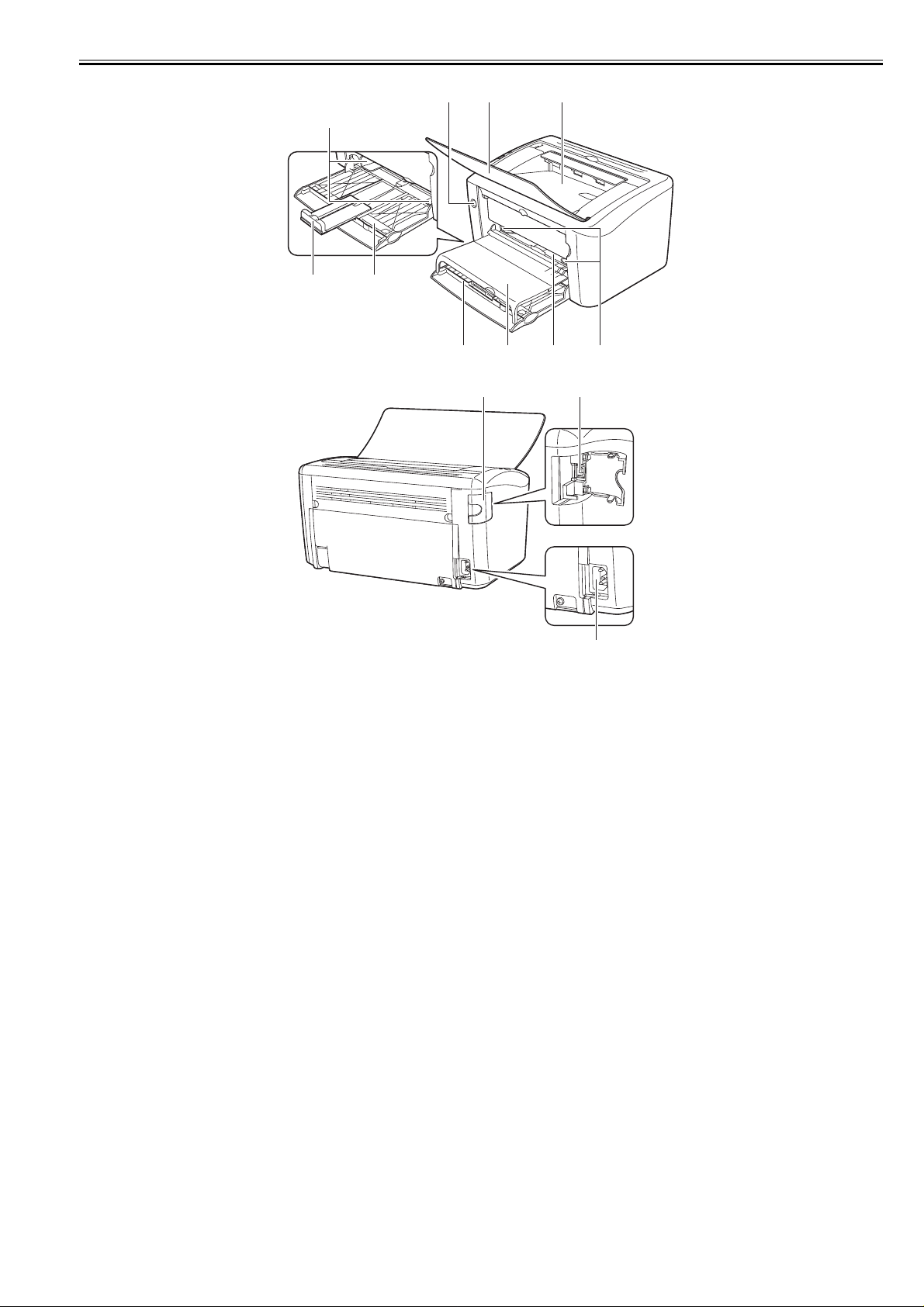
[1] Poewr switch [2] Delivery auxiliary tray
[3] Delivery tray [4] Manual feed tray paper guide
[5] Manual feed tray [6] Tray cover
[7] Pickup tray [8] Small size paper guide
[9] Rear paper guide [10] Manual feed tray Paper guide
[11] USB cover [12] USB connector
[13] Power receptacle
0019-5264
1-5
Chapter 1
[1] [2] [3] [4] [5]
[6]
1.3.3 External View
LBP6000 / LBP6000B
[13]
[8][9][11][12] [10]
F-1-2
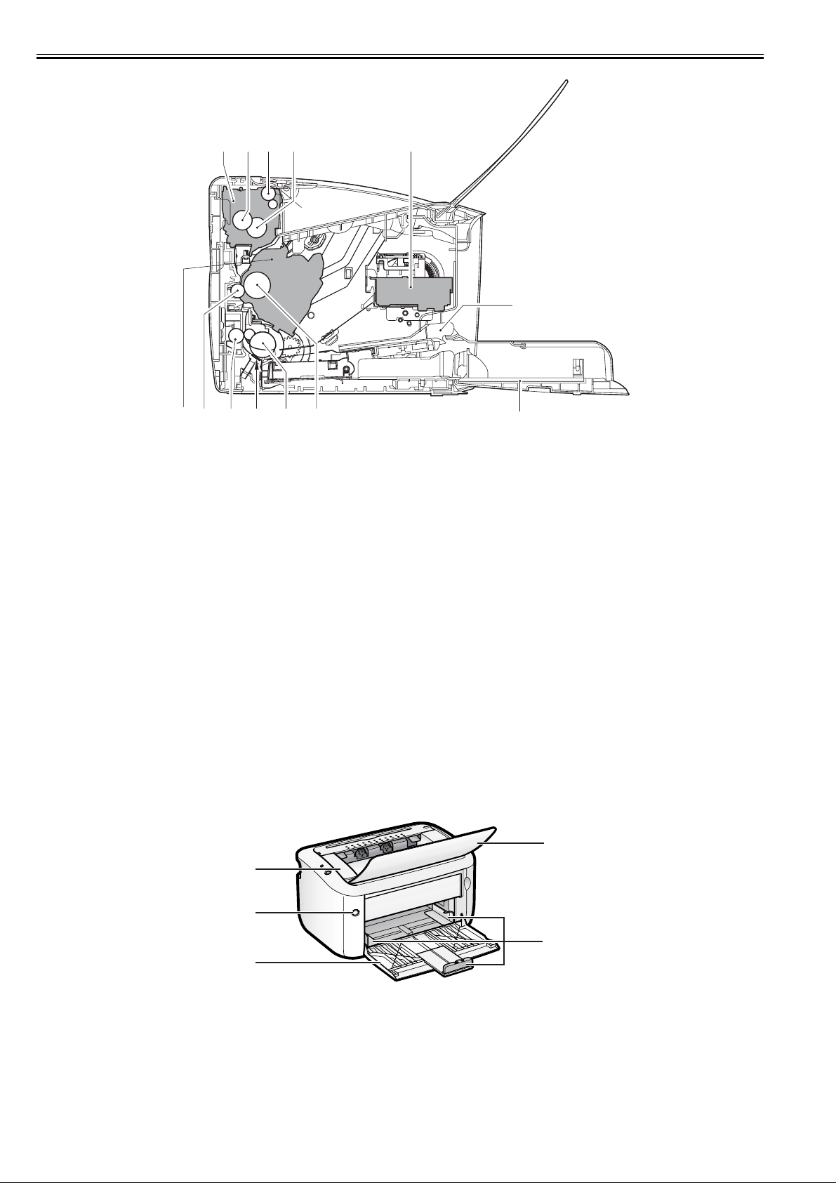
[1] Fixing unit [2] Pressure roller
[3] Delivery roller [4] Fixing film unit
[5] Laser scanner unit [6] Manual feed tray
[7] Pickup tray [8] Photosensitive drum
[9] Pickup roller [10] separation pad
[11] Feed roller [12] Transfer roller
[13] Toner cartridge
[7]
0025-1122
1-6
(4)
(1)
(2)
(5)
(3)
F-1-3
(6)
F-1-4
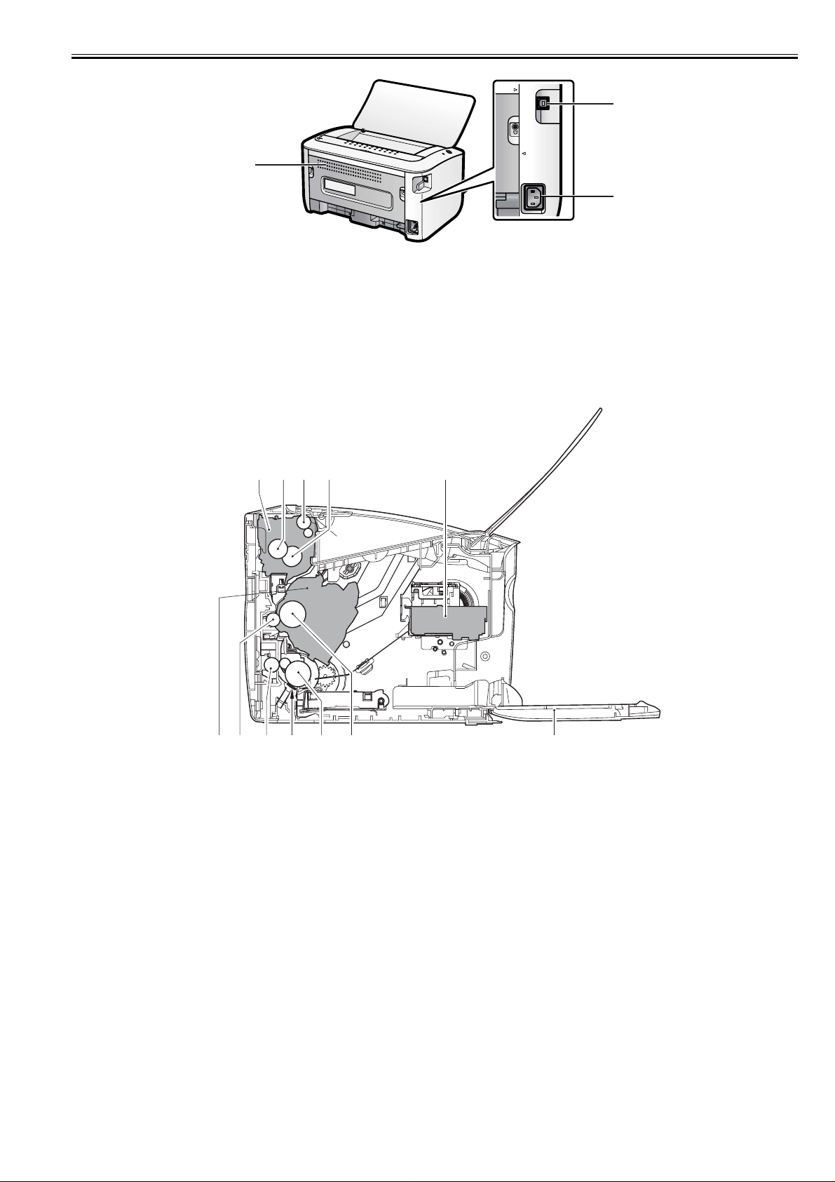
[1]Top Cover [2]Power Switch
[3]Multi-purpose Tray [4]Output Tray
[5]Paper Guide [6]Rear Cover
[7]USB Connector [8]Power Socket
Chapter 1
(7)
(8)
1.3.4 Cross Section
LBP6000 / LBP6000B
[1] [2] [3] [4] [5]
[10][11] [9][12]
F-1-5
0025-1123
[6][7][8]
[1] Fixing unit [2] Pressure roller
[3] Delivery roller [4] Fixing film unit
[5] Laser scanner unit [6] Pickup tray
[7] Photosensitive drum [8] Pickup roller
[9] separation pad [10] Feed roller
[11] Transfer roller [12] Toner cartridge
1-7
Chapter 1
1.4 Using the Machine
1.4.1 Control Panel
LBP3100 / LBP3010B
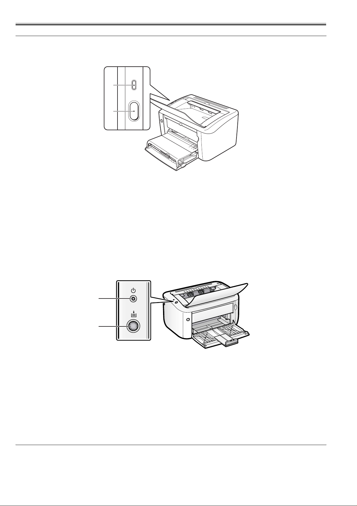
[1]
[2]
F-1-6
[1] Power lamp (green)
Lighting:
Indicates that the power of the host machine is turned on.
Not lighting:
Indicates that the power of the host machine is not turned on.
[2] Paper lamp/paper key (red)
<Lamp>
Flashing:
Indicates that there is no paper in the pickup source and print cannot be executed, or papers cannot be fed correctly.
Not lighting:
Indicates that the machine can make prints.
<Key>
Pressing this key after executing pickup of paper or jam removal restarts printing.
1.4.2 Control Panel
LBP6000 / LBP6000B
0019-5284
0025-1124
(1)
(2)
F-1-7
[1] Power lamp (green)
Lighting:
Indicates that the power of the host machine is turned on.
Not lighting:
Indicates that the power of the host machine is not turned on.
[2] Paper lamp/paper key (red)
<Lamp>
Flashing:
Indicates that there is no paper in the pickup source and print cannot be executed, or papers cannot be fed correctly.
Not lighting:
Indicates that the machine can make prints.
<Key>
Pressing this key after executing pickup of paper or jam removal restarts printing.
1.5 Safety
1.5.1 Safety of Laser Light
LBP3100 / LBP3010B
Laser light can be extremely hazardous to the human body.
0019-1859
1-8

Chapter 1
The machines laser scanning system is contained in a protective housing and external covers to prevent escape of laser light outside the machine. In other words,
the user is free of laser-related hazards as long as the machine is being used for its intended purposes.
The following warnings are given to comply with Safety Principles (EN60950).
Laserstrahlen können für den menschlichen Körper gefährlich sein. Aus diesem Grund ist das optische Lasersystem mit einem Schutzgehäuse un d einer Außenabdeckung dicht verschlossen und hat eine Struktur, die keine Laserstrahlen nach außen dringen lässt. Unter der Voraussetzun g, dass der Benutzer dieses Gerät normal
bedient, ist ein Austritt von Laserstrahlen daher ausgeschlossen.
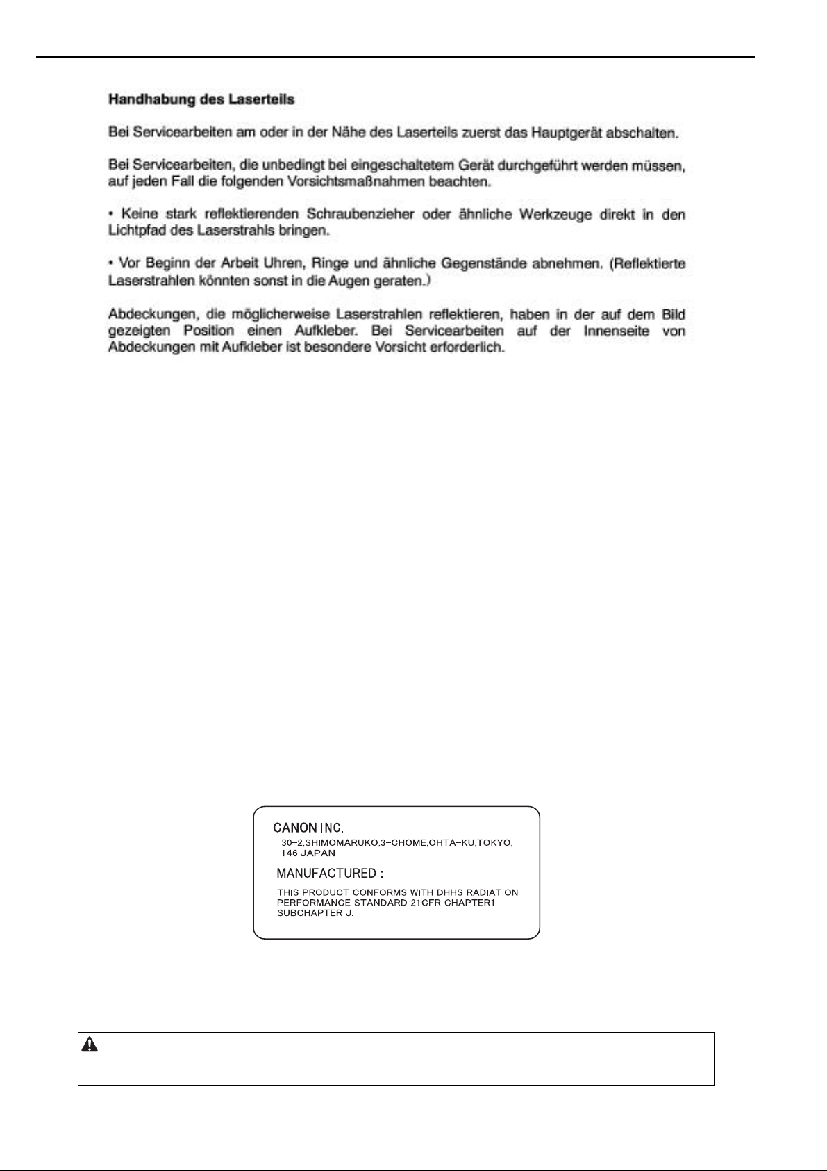
1.5.2 CDRH Regulations
LBP3100 / LBP3010B
0019-1860
The Center for Devices and Radiological Health of the US Food and Drug Administration put into effect regulations concerning laser products on August 2, 1976.
These regulations apply to products produced on and after August 1, 1976, and prohibit the sale of laser products without certification. The following is a label used
to certify compliance with the CDRH regulations, and all laser products to be sold in the US must bear this label.
F-1-8
1.5.3 Safety of Toner
LBP3100 / LBP3010B
0019-1855
The machines toner is a non-toxic material made up of plastic, iron, and small amounts of dye.
Do not throw toner into fire. Doing so can lead to explosion.
Toner on Clothing or Skin
1.Remove toner from clothing or skin, and wash with water.
2.Do not use warm or hot water, which will cause the toner to turn jelly-like and fuse permanently with the fibers of clothing.
3.Toner tends to react readily with vinyl. Do not bring it in contact.
Be sure to avoid using a transparent case made from vinyl chloride.
If it is in contact with a copy surface, the toner on it may melt, causing the case and the paper to stick to each other.
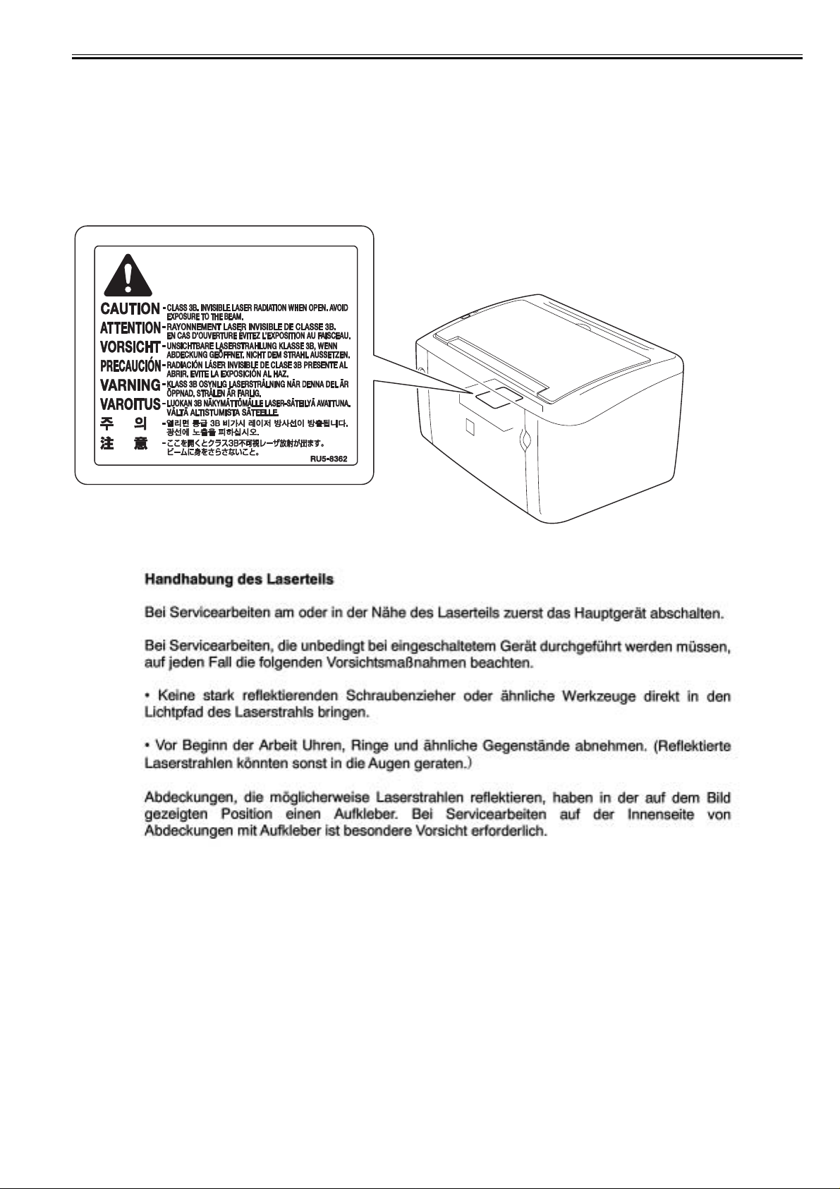
1.5.4 Handling the Laser Unit
LBP3100 / LBP3010B
0019-1863
The laser/scanner unit emits invisible laser beam. DO NOT disassemble the unit as the laser beam can possibly damage your eyes. The unit cannot be adjusted in
the field. The following label is attached to the cover of the unit:
F-1-9
1-9
Chapter 1
F-1-10
1.5.5 Points to Note at Disassembly/Assembly Work
LBP3100 / LBP3010B
0019-1869
Be sure to ensure the following notes when performing disassembly/assembly work.
1. Be sure to disconnect the power plug for safety when performing disassembly/assembly work.
2. As for assembly procedure, perform the reverse procedure of disassembly unless otherwise instructed.
3. Avoid making mistakes in the type of screws (length/diameter) and usage locations for assembly.
4. Screws w/washer are used as mounting screws for grounding wires and varistors with the aim of checking electric continuity. Be sure to use this screw for assembly.
5. Basically, do not activate the machine with their parts being removed.
6. Do not remove paintlock screws at the time of disassembly.
1.5.6 Safety of Laser Light
LBP6000 / LBP6000B
0025-1128
Laser light can be extremely hazardous to the human body.
The machines laser scanning system is contained in a protective housing and external covers to prevent escape of laser light outside the machine. In other words,
the user is free of laser-related hazards as long as the machine is being used for its intended purposes.
The following warnings are given to comply with Safety Principles (EN60950).
Laserstrahlen können für den menschlichen Körper gefährlich sein. Aus diesem Grund ist das optische Lasersystem mit einem Schutzgehäuse und einer Außenabdeckung dicht verschlossen und hat eine Struktur, die keine L aserstrahlen nach außen dringen lässt. Unter der Voraussetzung, dass der Benutzer d ieses Gerät normal
bedient, ist ein Austritt von Laserstrahlen daher ausgeschlossen.
1.5.7 CDRH Regulations
LBP6000 / LBP6000B
The Center for Devices and Radiological Health of the US Food and Drug Administration put into effect regulations concerning laser products on August 2, 1976.
These regulations apply to products produced on and after August 1, 1976, and prohibit the sale of laser products without certification. The following is a label used
0025-1129
to certify compliance with the CDRH regulations, and all laser products to be sold in the US must bear this label.
F-1-11
1.5.8 Safety of Toner
LBP6000 / LBP6000B
The machines toner is a non-toxic material made up of plastic, iron, and small amounts of dye.
Do not throw toner into fire. Doing so can lead to explosion.
1-10
0025-1131
Chapter 1
Toner on Clothing or Skin
1.Remove toner from clothing or skin, and wash with water.
2.Do not use warm or hot water, which will cause the toner to turn jelly-like and fuse permanently with the fibers of clothing.
3.Toner tends to react readily with vinyl. Do not bring it in contact.
Be sure to avoid using a transparent case made from vinyl chloride.
If it is in contact with a copy surface, the toner on it may melt, causing the case and the paper to stick to each other.
1.5.9 Handling the Laser Unit
LBP6000 / LBP6000B
0025-1133
The laser/scanner unit emits invisible laser beam. DO NOT disassemble the unit as the laser beam can possibly damage your eyes. The unit cannot be adjusted in
the field. The following label is attached to the cover of the unit:
F-1-12
F-1-13
1.5.10 Points to Note at Disassembly/Assembly Work
LBP6000 / LBP6000B
0025-1134
Be sure to ensure the following notes when performing disassembly/assembly work.
1. Be sure to disconnect the power plug for safety when performing disassembly/assembly work.
2. As for assembly procedure, perform the reverse procedure of disassembly unless otherwise instructed.
3. Avoid making mistakes in the type of screws (length/diameter) and usage locations for assembly.
4. Screws w/washer are used as mounting screws for grounding wires and varistors with the aim of checking electric continuity. Be sure to use this screw for assembly.
5. Basically, do not activate the machine with their parts being removed.
6. Do not remove paintlock screws at the time of disassembly.
1-11


Chapter 2 TECHNICAL REFERENCE

 Loading...