

Canon LBP2900 series, LBP3000 series Service Manual

HTTP://WWW.FIXCLUB.COM.CN
Service Manual
LBP3000/2900 Series
LBP2900
Mar 10 2005

HTTP://WWW.FIXCLUB.COM.CN

HTTP://WWW.FIXCLUB.COM.CN
Application
This manual has been issued by Canon Inc. for qualified persons to learn technical theory, installation, maintenance, and repair
of products. This manual covers all localities where the products are sold. For this reason, there may be information in this
manual that does not apply to your locality.
Corrections
This manual may contain technical inaccuracies or typographical errors due to improvements or changes in products. When
changes occur in applicable products or in the contents of this manual, Canon will release technical information as the need
arises. In the event of major changes in the contents of this manual over a long or short period, Canon will issue a new edition
of this manual.
The following paragraph does not apply to any countries where such provisions are inconsistent with local law.
Trademarks
The product names and company names used in this manual are the registered trademarks of the individual companies.
Copyright
This manual is copyrighted with all rights reserved. Under the copyright laws, this manual may not be copied, reproduced or
translated into another language, in whole or in part, without the written consent of Canon Inc.
COPYRIGHT © 2001 CANON INC.
Printed in Japan
Caution
Use of this manual should be strictly supervised to avoid disclosure of confidential information.

HTTP://WWW.FIXCLUB.COM.CN
Symbols Used
This documentation uses the following symbols to indicate special information:
Symbol Description
Indicates an item of a non-specific nature, possibly classified as Note, Caution, or Warning.
Indicates an item requiring care to avoid electric shocks.
Indicates an item requiring care to avoid combustion (fire).
Indicates an item prohibiting disassembly to avoid electric shocks or problems.
Indicates an item requiring disconnection of the power plug from the electric outlet.
Indicates an item intended to provide notes assisting the understanding of the topic in question.
Memo
Introduction
REF.
Indicates an item of reference assisting the understanding of the topic in question.
Provides a description of a service mode.
Provides a description of the nature of an error indication.

HTTP://WWW.FIXCLUB.COM.CN
Introduction
The following rules apply throughout this Service Manual:
1. Each chapter contains sections explaining the purpose of specific functions and the relationship between electrical and
mechanical systems with reference to the timing of operation.
Å@In the diagrams, represents the path of mechanical drive; where a signal name accompanies the symbol , the
arrow indicates the direction of the electric signal.
Å@The expression "turn on the power" means flipping on the power switch, closing the front door, and closing the delivery
unit door, which results in supplying the machine with power.
2. In the digital circuits, '1'is used to indicate that the voltage level of a given signal is "High", while '0' is used to indicate
"Low".(The voltage value, however, differs from circuit to circuit.) In addition, the asterisk (*) as in "DRMD*" indicates
that the DRMD signal goes on when '0'.
In practically all cases, the internal mechanisms of a microprocessor cannot be checked in the field. Therefore, the
operations of the microprocessors used in the machines are not discussed: they are explained in terms of from sensors to
the input of the DC controller PCB and from the output of the DC controller PCB to the loads.
The descriptions in this Service Manual are subject to change without notice for product improvement or other purposes, and major changes will be
communicated in the form of Service Information bulletins.
All service persons are expected to have a good understanding of the contents of this Service Manual and all relevant Service Information bulletins and be
able to identify and isolate faults in the machine."

HTTP://WWW.FIXCLUB.COM.CN

HTTP://WWW.FIXCLUB.COM.CN
Contents
Contents
Chapter 1 PRODUCT DESCRIPTION
1.1 Features ..................................................................................................................................................... 1- 1
1.1.1 Features ..................................................................................................................................................................1- 1
1.2 Product Specifications ................................................................................................................................1- 2
1.2.1 Machine Specifications............................................................................................................................................ 1- 2
1.3 Name of Parts.............................................................................................................................................1- 3
1.3.1 External View...........................................................................................................................................................1- 3
1.3.2 Cross Section View .................................................................................................................................................1- 3
1.4 Using the Machine......................................................................................................................................1- 5
1.4.1 Control Panel........................................................................................................................................................... 1- 5
1.5 Safety .........................................................................................................................................................1- 6
1.5.1 Safety of Laser Light................................................................................................................................................1- 6
1.5.2 Regulations Under the Center for Devices and Radiological Health (CDRH) .........................................................1- 6
1.5.3 Safety of Toner........................................................................................................................................................1- 6
1.5.4 Handling the Laser Unit ...........................................................................................................................................1- 6
Chapter 2 TECHNICAL REFERENCE
2.1 Functional Configuration............................................................................................................................. 2- 1
2.1.1 Outline .....................................................................................................................................................................2- 1
2.2 Basic Sequense..........................................................................................................................................2- 2
2.2.1 Basic Operation Sequence......................................................................................................................................2- 2
2.2.2 Power-on sequence.................................................................................................................................................2- 2
2.3 LASER EXPOSURE SYSTEM ...................................................................................................................2- 3
2.3.1 Overview/Configuration ........................................................................................................................................... 2- 3
2.3.1.1 Overview .................................................................................................................................................................................. 2- 3
2.3.2 Controlling the Laser Activation Timing ...................................................................................................................2- 3
2.3.2.1 Turning On/Off the Laser ......................................................................................................................................................... 2- 3
2.3.2.2 Horizontal Synchronization Control.......................................................................................................................................... 2- 4
2.3.3 Laser Control ...........................................................................................................................................................2- 4
2.3.3.1 Auto Photo Current Control...................................................................................................................................................... 2- 4
2.3.4 Laser Scanner Motor Control .................................................................................................................................. 2- 5
2.3.4.1 Outline...................................................................................................................................................................................... 2- 5
2.3.4.2 Scanner Motor Speed Control ................................................................................................................................................. 2- 5
2.3.4.3 Detection of a Fault in the Scanner Motor ............................................................................................................................... 2- 5
2.4 IMAGE FORMATION SYSTEM.................................................................................................................. 2- 6
2.4.1 Overview/Configuration ........................................................................................................................................... 2- 6
2.4.1.1 Construction ............................................................................................................................................................................. 2- 6
2.4.1.2 Printing Process....................................................................................................................................................................... 2- 6
2.4.1.3 Latent Image Formation Block ................................................................................................................................................. 2- 7
2.4.1.4 Development Block .................................................................................................................................................................. 2- 8
2.4.1.5 Transfer Block.......................................................................................................................................................................... 2- 9
2.4.1.6 Fixing Block............................................................................................................................................................................ 2- 10
2.4.1.7 Drum Cleaning Block ............................................................................................................................................................. 2- 11
2.4.2 High-Voltage Control .............................................................................................................................................2- 11
2.4.2.1 Outline.................................................................................................................................................................................... 2- 11
2.4.2.2 Generation of the Primary Charging Bias .............................................................................................................................. 2- 12
2.4.2.3 Generation of the Developing Bias ........................................................................................................................................ 2- 12
2.4.2.4 Generation of the Transfer Charging Bias ............................................................................................................................. 2- 12
2.4.3 Toner Cartridge .....................................................................................................................................................2- 13
2.4.3.1 Checking the Presence/Absence of a Toner Cartridge.......................................................................................................... 2- 13
2.4.3.2 Checking the Level of Toner .................................................................................................................................................. 2- 13

HTTP://WWW.FIXCLUB.COM.CN
Contents
2.5 PICKUP AND FEEDING SYSTEM........................................................................................................... 2- 14
2.5.1 Overview/Configuration..........................................................................................................................................2- 14
2.5.1.1 Outline.................................................................................................................................................................................... 2- 14
2.5.2 Detecting Jams ......................................................................................................................................................2- 14
2.5.2.1 Jam Detection Outline............................................................................................................................................................ 2- 14
2.5.2.2 Delay Jams ............................................................................................................................................................................ 2- 15
2.5.2.3 Stationary Jams ..................................................................................................................................................................... 2- 15
2.5.2.4 Other Jams ............................................................................................................................................................................ 2- 15
2.5.3 Multi-purpose Pickup .............................................................................................................................................2- 15
2.5.3.1 Pickup from the Pickup Tray/Manual Feed Tray .................................................................................................................... 2- 15
2.6 EXTERNAL AND CONTROLS SYSTEM ................................................................................................. 2- 17
2.6.1 Power Supply.........................................................................................................................................................2- 17
2.6.1.1 Power Supply ......................................................................................................................................................................... 2- 17
2.6.1.2 Protective Functions .............................................................................................................................................................. 2- 17
2.7 ENGINE CONTROL SYSTEM ................................................................................................................. 2- 19
2.7.1 Video Controller .....................................................................................................................................................2- 19
2.7.1.1 Overview ................................................................................................................................................................................ 2- 19
2.7.1.2 Outline of Operation by Block ................................................................................................................................................ 2- 19
2.7.2 Engine Controller ...................................................................................................................................................2- 20
2.7.2.1 Outline.................................................................................................................................................................................... 2- 20
2.8 FIXING UNIT/DELIVERY SYSTEM.......................................................................................................... 2- 21
2.8.1 Overview/Configuration..........................................................................................................................................2- 21
2.8.1.1 Overview ................................................................................................................................................................................ 2- 21
2.8.1.2 Major Components of the Fixing Assembly ........................................................................................................................... 2- 21
2.8.2 Various Control Mechanisms.................................................................................................................................2- 22
2.8.2.1 Fixing Temperature Control ................................................................................................................................................... 2- 22
2.8.2.2 Protective Functions .............................................................................................................................................................. 2- 24
Chapter 3 DISASSEMBLY AND ASSEMBLY
3.1 EXTERNAL AND CONTROLS SYSTEM ................................................................................................... 3- 1
3.1.1 Rear Cover...............................................................................................................................................................3- 1
3.1.1.1 Removing the Right Cover ....................................................................................................................................................... 3- 1
3.1.1.2 Removing the Left Cover ......................................................................................................................................................... 3- 1
3.1.1.3 Removing the Front Cover ....................................................................................................................................................... 3- 1
3.1.1.4 Removing the Upper Cover ..................................................................................................................................................... 3- 2
3.1.2 Right Cover..............................................................................................................................................................3- 2
3.1.2.1 Removing the Right Cover ....................................................................................................................................................... 3- 2
3.1.3 Left Cover ................................................................................................................................................................3- 3
3.1.3.1 Removing the Left Cover ......................................................................................................................................................... 3- 3
3.1.4 Upper Cover.............................................................................................................................................................3- 3
3.1.4.1 Removing the Right Cover ....................................................................................................................................................... 3- 3
3.1.4.2 Removing the Left Cover ......................................................................................................................................................... 3- 3
3.1.4.3 Removing the Front Cover ....................................................................................................................................................... 3- 4
3.1.4.4 Removing the Upper Cover ..................................................................................................................................................... 3- 4
3.1.5 Front Cover..............................................................................................................................................................3- 5
3.1.5.1 Removing the Right Cover ....................................................................................................................................................... 3- 5
3.1.5.2 Removing the Left Cover ......................................................................................................................................................... 3- 5
3.1.5.3 Removing the Front Cover ....................................................................................................................................................... 3- 6
3.1.6 Delivery Tray............................................................................................................................................................3- 6
3.1.6.1 Removing the Delivery Tray..................................................................................................................................................... 3- 6
3.1.7 Pickup Tray..............................................................................................................................................................3- 6
3.1.7.1 Removing the Pickup Tray ....................................................................................................................................................... 3- 6
3.1.8 Engine controller board............................................................................................................................................3- 6
3.1.8.1 Removing the Right Cover ....................................................................................................................................................... 3- 6
3.1.8.2 Removing the Left Cover ......................................................................................................................................................... 3- 7
3.1.8.3 Removing the Front Cover ....................................................................................................................................................... 3- 7
3.1.8.4 Removing the Engine Controller PCB...................................................................................................................................... 3- 7
3.1.9 Video Controller Board.............................................................................................................................................3- 8

HTTP://WWW.FIXCLUB.COM.CN
Contents
3.1.9.1 Removing the Right Cover ....................................................................................................................................................... 3- 8
3.1.10 Power supply board ...............................................................................................................................................3- 8
3.1.10.1 Removing the Right Cover ..................................................................................................................................................... 3- 8
3.1.10.2 Removing the Left Cover ....................................................................................................................................................... 3- 9
3.1.10.3 Removing the Front Cover ..................................................................................................................................................... 3- 9
3.1.10.4 Removing the Upper Cover.................................................................................................................................................. 3- 10
3.1.10.5 Removing the Rear Cover.................................................................................................................................................... 3- 10
3.1.10.6 Removing the Power Supply PCB ....................................................................................................................................... 3- 10
3.1.11 Top sensor...........................................................................................................................................................3- 11
3.1.11.1 Removing the Right Cover ................................................................................................................................................... 3- 11
3.1.11.2 Removing the Left Cover ..................................................................................................................................................... 3- 11
3.1.11.3 Removing the Front Cover ................................................................................................................................................... 3- 12
3.1.11.4 Removing the Upper Cover.................................................................................................................................................. 3- 12
3.1.11.5 Removing the Rear Cover.................................................................................................................................................... 3- 12
3.1.11.6 Removing the Paper Leading Edge/Paper Width Sensor PCB............................................................................................ 3- 13
3.2 LASER EXPOSURE SYSTEM .................................................................................................................3- 14
3.2.1 Laser Scanner Unit................................................................................................................................................3- 14
3.2.1.1 Removing the Right Cover ..................................................................................................................................................... 3- 14
3.2.1.2 Removing the Left Cover ....................................................................................................................................................... 3- 14
3.2.1.3 Removing the Front Cover ..................................................................................................................................................... 3- 14
3.2.1.4 Removing the Engine Controller PCB.................................................................................................................................... 3- 15
3.2.1.5 Removing the Laser Scanner Unit ......................................................................................................................................... 3- 15
3.3 IMAGE FORMATION SYSTEM................................................................................................................ 3- 16
3.3.1 Transfer Charging Roller .......................................................................................................................................3- 16
3.3.1.1 Removing the Transfer Charging Roller ................................................................................................................................ 3- 16
3.4 PICKUP AND FEEDING SYSTEM ...........................................................................................................3- 17
3.4.1 Pickup Unit ............................................................................................................................................................3- 17
3.4.1.1 Removing the Transfer Charging Roller ................................................................................................................................ 3- 17
3.4.1.2 Removing the Right Cover ..................................................................................................................................................... 3- 17
3.4.1.3 Removing the Left Cover ....................................................................................................................................................... 3- 17
3.4.1.4 Removing the Front Cover ..................................................................................................................................................... 3- 18
3.4.1.5 Removing the Upper Cover ................................................................................................................................................... 3- 18
3.4.1.6 Removing the Rear Cover ..................................................................................................................................................... 3- 18
3.4.1.7 Removing the Power Supply PCB ......................................................................................................................................... 3- 19
3.4.1.8 Removing the Fixing Assembly.............................................................................................................................................. 3- 19
3.4.1.9 Removing the Pickup Assembly ............................................................................................................................................ 3- 19
3.4.2 Manual Pickup Roller............................................................................................................................................. 3- 19
3.4.2.1 Removing the Pickup Roller................................................................................................................................................... 3- 19
3.4.3 Multi-purpose Pickup Solenoid ..............................................................................................................................3- 20
3.4.3.1 Removing the Right Cover ..................................................................................................................................................... 3- 20
3.4.3.2 Removing the Pickup Solenoid .............................................................................................................................................. 3- 20
3.4.4 Manual Separation Pad .........................................................................................................................................3- 20
3.4.4.1 Removing the Separation Pad ............................................................................................................................................... 3- 20
3.4.5 Main Motor.............................................................................................................................................................3- 20
3.4.5.1 Removing the Right Cover ..................................................................................................................................................... 3- 20
3.4.5.2 Removing the Left Cover ....................................................................................................................................................... 3- 21
3.4.5.3 Removing the Front Cover ..................................................................................................................................................... 3- 21
3.4.5.4 Removing the Engine Controller PCB.................................................................................................................................... 3- 21
3.4.5.5 Removing the Laser Scanner Unit ......................................................................................................................................... 3- 22
3.4.5.6 Removing the Main Motor ...................................................................................................................................................... 3- 22
3.5 FIXING SYSTEM ......................................................................................................................................3- 23
3.5.1 Fixing Unit..............................................................................................................................................................3- 23
3.5.1.1 Removing the Right Cover ..................................................................................................................................................... 3- 23
3.5.1.2 Removing the Left Cover ....................................................................................................................................................... 3- 23
3.5.1.3 Removing the Front Cover ..................................................................................................................................................... 3- 23
3.5.1.4 Removing the Upper Cover ................................................................................................................................................... 3- 24
3.5.1.5 Removing the Rear Cover ..................................................................................................................................................... 3- 24
3.5.1.6 Removing the Power Supply PCB ......................................................................................................................................... 3- 24
3.5.1.7 Removing the Fixing Assembly.............................................................................................................................................. 3- 25
3.5.2 Fixing Film Unit......................................................................................................................................................3- 25

HTTP://WWW.FIXCLUB.COM.CN
Contents
3.5.2.1 Removing the Right Cover ..................................................................................................................................................... 3- 25
3.5.2.2 Removing the Left Cover ....................................................................................................................................................... 3- 25
3.5.2.3 Removing the Front Cover ..................................................................................................................................................... 3- 26
3.5.2.4 Removing the Upper Cover ................................................................................................................................................... 3- 26
3.5.2.5 Removing the Rear Cover ..................................................................................................................................................... 3- 26
3.5.2.6 Removing the Power Supply PCB ......................................................................................................................................... 3- 27
3.5.2.7 Removing the Fixing Assembly.............................................................................................................................................. 3- 27
3.5.2.8 Removing the Fixing Film Unit ............................................................................................................................................... 3- 27
3.5.3 Fixing Pressure Roller............................................................................................................................................3- 27
3.5.3.1 Removing the Right Cover ..................................................................................................................................................... 3- 27
3.5.3.2 Removing the Left Cover ....................................................................................................................................................... 3- 28
3.5.3.3 Removing the Front Cover ..................................................................................................................................................... 3- 28
3.5.3.4 Removing the Upper Cover ................................................................................................................................................... 3- 29
3.5.3.5 Removing the Rear Cover ..................................................................................................................................................... 3- 29
3.5.3.6 Removing the Power Supply PCB ......................................................................................................................................... 3- 29
3.5.3.7 Removing the Fixing Assembly.............................................................................................................................................. 3- 30
3.5.3.8 Removing the Fixing Film Unit ............................................................................................................................................... 3- 30
3.5.3.9 Removing the Pressure Roller ............................................................................................................................................... 3- 30
3.5.4 Delivery Sensor......................................................................................................................................................3- 30
3.5.4.1 Removing the Right Cover ..................................................................................................................................................... 3- 30
3.5.4.2 Removing the Left Cover ....................................................................................................................................................... 3- 31
3.5.4.3 Removing the Front Cover ..................................................................................................................................................... 3- 31
3.5.4.4 Removing the Upper Cover ................................................................................................................................................... 3- 32
3.5.4.5 Removing the Rear Cover ..................................................................................................................................................... 3- 32
3.5.4.6 Removing the Delivery Sensor .............................................................................................................................................. 3- 32
Chapter 4 MAINTENANCE AND INSPECTION
4.1 Periodically Replaced Parts ....................................................................................................................... 4- 1
4.1.1 Periodic Replacement Parts ....................................................................................................................................4- 1
4.2 Consumables ............................................................................................................................................. 4- 2
4.2.1 Consumable Parts ...................................................................................................................................................4- 2
4.3 Periodical Service....................................................................................................................................... 4- 3
4.3.1 Periodic Service.......................................................................................................................................................4- 3
4.4 Cleaning ..................................................................................................................................................... 4- 4
4.4.1 Items to Clean..........................................................................................................................................................4- 4
4.4.2 Cleaning (external covers).......................................................................................................................................4- 4
4.4.3 Cleaning (printer unit) ..............................................................................................................................................4- 4
Chapter 5 TROUBLESHOOTING
5.1 MEASUREMENT AND ADJUSTMENT......................................................................................................5- 1
5.1.1 Mechanical Adjustment............................................................................................................................................5- 1
5.1.1.1 Checking the Pressure of the Pressure Roller (nip)................................................................................................................. 5- 1
5.2 SERVICE TOOLS ...................................................................................................................................... 5- 2
5.2.1 Special Tools ...........................................................................................................................................................5- 2
5.2.2 Solvent/Oil List.........................................................................................................................................................5- 2
5.3 Location of Convectors............................................................................................................................... 5- 3
5.3.1 Location of Convectors ............................................................................................................................................5- 3
5.4 ERROR CODE TABLE............................................................................................................................... 5- 4
5.4.1 Overview..................................................................................................................................................................5- 4
5.4.2 Service Messages....................................................................................................................................................5- 4
Chapter 6 APPENDIX
6.1 OUTLINE OF ELECTRICAL COMPONENTS ............................................................................................ 6- 1
6.1.1 Clutch/Solenoid........................................................................................................................................................6- 1
6.1.1.1 Solenoid ................................................................................................................................................................................... 6- 1

HTTP://WWW.FIXCLUB.COM.CN
Contents
6.1.2 Motor .......................................................................................................................................................................6- 2
6.1.2.1 Motor........................................................................................................................................................................................ 6- 2
6.1.3 Sensor .....................................................................................................................................................................6- 3
6.1.3.1 Sensor...................................................................................................................................................................................... 6- 3
6.1.4 Switch ......................................................................................................................................................................6- 4
6.1.4.1 Switch ...................................................................................................................................................................................... 6- 4
6.1.5 Lamps, Heaters, and Others ...................................................................................................................................6- 5
6.1.5.1 Heater ...................................................................................................................................................................................... 6- 5
6.1.6 PCBs .......................................................................................................................................................................6- 6
6.1.6.1 PCBs........................................................................................................................................................................................ 6- 6

HTTP://WWW.FIXCLUB.COM.CN
Contents

HTTP://WWW.FIXCLUB.COM.CN
Chapter 1 PRODUCT DESCRIPTION

HTTP://WWW.FIXCLUB.COM.CN

HTTP://WWW.FIXCLUB.COM.CN
Contents
Contents
1.1 Features ..........................................................................................................................................................................1-1
1.1.1 Features ........................................................................................................................................................................................ 1-1
1.2 Product Specifications....................................................................................................................................................1-2
1.2.1 Machine Specifications ................................................................................................................................................................ 1-2
1.3 Name of Parts.................................................................................................................................................................1-3
1.3.1 External View .............................................................................................................................................................................. 1-3
1.3.2 Cross Section View...................................................................................................................................................................... 1-3
1.4 Using the Machine .........................................................................................................................................................1-5
1.4.1 Control Panel ............................................................................................................................................................................... 1-5
1.5 Safety .............................................................................................................................................................................1-6
1.5.1 Safety of Laser Light ................................................................................................................................................................... 1-6
1.5.2 Regulations Under the Center for Devices and Radiological Health (CDRH)............................................................................ 1-6
1.5.3 Safety of Toner ............................................................................................................................................................................ 1-6
1.5.4 Handling the Laser Unit............................................................................................................................................................... 1-6

HTTP://WWW.FIXCLUB.COM.CN

HTTP://WWW.FIXCLUB.COM.CN
Chapter 1
1.1 Features
1.1.1 Features
1. High-Speed, Compact Mono-Color Printer
The machine’s body is compact in design perfectly suited for installation on a desk, and yet it is a mono-color printer capable of turning out as many as
12.0 prints (A4) every minute.
2. Shorter Wait Time and Lower Power Consumption
The machine uses an on-demand fixing method, enabling a shorter wait time and lower power consumption when compared with machines that use a roller
fixing method.
0009-2599
1-1

HTTP://WWW.FIXCLUB.COM.CN
Chapter 1
1.2 Product Specifications
1.2.1 Machine Specifications
Body installation method desktop page printer
Photosensitive medium OPC drum
Exposure method semiconductor laser
Development method toner projection
Transfer method roller transfer
Separation method curvature separation
Cassette pickup method pad separation (pickup from pickup tray)
Multifeeder pickup method pad separation (pickup from manual feed tray)
Drum cleaning method blade
Fixing method on-demand fixing
Delivery method face-down
Toner supply type toner cartridge (about 2000 prints; A4, single-sided, image ratio
Warm-up time 0 sec (from standby; if from power-on, 10 sec or less)
Print area area 5 mm from paper edges
Printing resolution 600dpi
First print time 9.3 sec or less (approx.; A4)
Print speed (A4) 12 pages/min (approx.)
Print speed(LTR) 12 pages/min (approx.)
Cassette paper size A4, B5, A5, LGL, LTR, Executive, postcard, envelope, user-
Multi-purpose paper size A4, B5, A5, LGL, LTR, Executive, postcard, envelope, user-
Cassette paper type plain paper (64 to 90 g/m2), heavy paper (91 to 163 g/m2),
Multi-purpose paper type plain paper (64 to 90 g/m2), heavy paper (91 to 163 g/m2),
Cassette capacity if plain paper, about 150 sheets (64g/m2); if heavy paper, about
Multi-purpose capacity 1 sheet
Delivery tray stack if plain paper, about 100 sheets (64g/m2); if heavy paper, about
Memory 2 MB (internal; no option)
Operating environment
(Temperature range)
Operating environment
(Humidity range)
Noise 62 dB or less (during printing; nominal noise rating based on
Power supply rating 220 to 240 VAC +/-10% (50 Hz +/-2 Hz)
Power consumption
(Maximum)
Dimensions 370 (W) x 251 (D) x 216 (H) mm (approx.)
Weight printer unit: about 5.3 kg; toner cartridge: about0.7kg
Option none
0009-2729
of 5%)
defined paper (76.2 to 215.9 mm in width, 127 to 355.6 mm in
length)
defined paper (76.2 to 215.9 mm in width, 127 to 355.6 mm in
length)
recycled paper, transparency, label sheet, postcard, envelope
recycled paper, transparency, label sheet, postcard, envelope
60 sheets (128g/m2);if transparency, about 100 sheets;if
postcard, about 30 sheets
30 sheets (128g/m2);if transparency, label sheet, envelope, or
postcard, about 10 sheets
7.5 to 35 deg C
5 ~ 90%RH
ISO9296)
body standard: 830 W or less (approx.; at 20 deg C room
temperature; including peak values in excess of 1 sec at input of
rated power)
1-2
HTTP://WWW.FIXCLUB.COM.CN
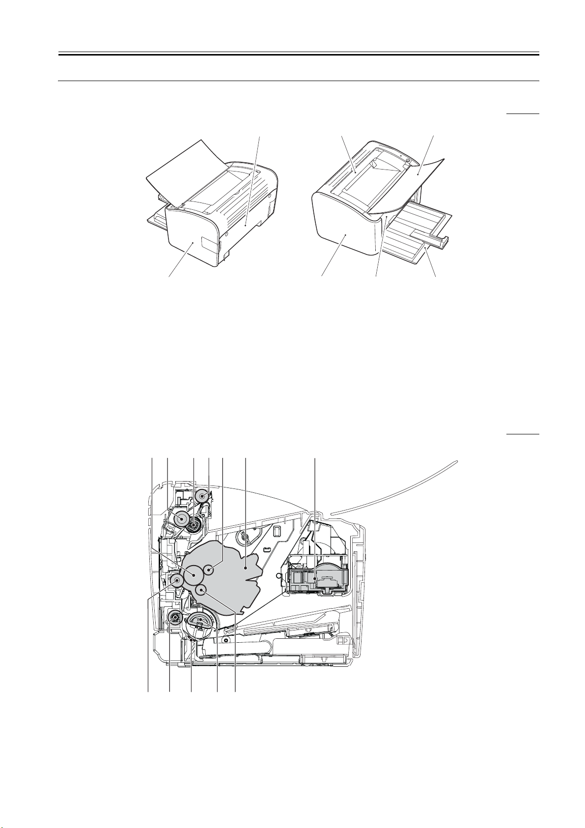
1.3 Name of Parts
1.3.1 External View
Chapter 1
0009-2753
[7]
[1]
F-1-1
T-1-1
[1] Rear cover [6] Left cover
[2] Upper cover [7] Right cover
[3] Delivery tray
[4] Pickup tray
[5] Front cover
[2]
[6]
[5]
[3]
[4]
1.3.2 Cross Section View
[1] [2] [3] [4] [5] [6] [7]
0007-6027
[8][9][10][11][12]
F-1-2
1-3

HTTP://WWW.FIXCLUB.COM.CN
Chapter 1
T-1-2
[1] Photosensitive drum [8] Developing cylinder
[2] Pressure roller [9] Pickup roller
[3] Fixing film assembly [10] Separation pad
[4] Delivery roller [11]Feed roller
[5] Primary charging roller [12] Transfer charging roller
[6] Toner cartridge
[7] Laser scanner assembly
1-4
HTTP://WWW.FIXCLUB.COM.CN
1.4 Using the Machine
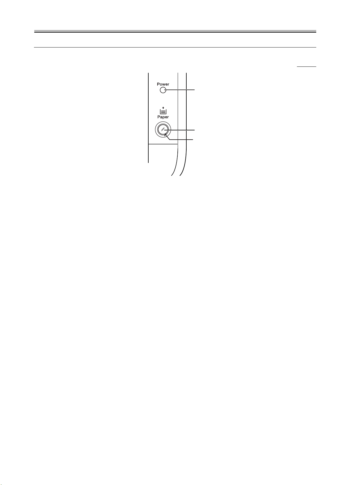
1.4.1 Control Panel
[1]
[2]
[3]
F-1-3
The machine is equipped with 2 lamps and 1 control key:
[1] Power Lamp
ON: indicates that the machine is supplied with power.
OFF: indicates that the machine is not supplied with power.
[2] Paper Lamp
flashing: indicates the absence of paper or the presence of a jam while a job is under way.
OFF: indicates the presence of a service error or the presence of a state other than the above.
[3] Paper Key
A press on this key after supplying paper or removing the jam will cause the machine to resume the suspended printing operation.
Chapter 1
0007-6034
1-5

HTTP://WWW.FIXCLUB.COM.CN
Chapter 1
1.5 Safety
1.5.1 Safety of Laser Light
Laser radiation could be hazardous to the human body. For this reason, laser radiation emitted inside this machine is hermetically sealed within the
protective housing and external cover. No radiation can leaak from the machine in the normal operation of the product by the user.
1.5.2 Regulations Under the Center for Devices and Radiological Health (CDRH)
The CDRH of the US Food and Drug Administration put into effect regulations governing the sale of laser products in the US on August 2, 1976. These
regulations apply to all laser products produced on and after August 1, 1976, and a laser product cannot be sold unless it has been certified to comply with
the regulations. The following is the label used to indicate that the product has been certified under the regulations, and all laser products sold in the US
must bear the label.
F-1-4
0007-6035
0007-6036
1.5.3 Safety of Toner
The machine's toner is a non-toxic material composed of plastic, iron, and small amounts of dye.
Do not put the toner into fire. It may explode.
Toner on the Skin or Clothes
1. If your skin or clothes came into contact with toner, use dry tissue to remove the toner, and then wash with water.
2. Do not use warm or hot water, which will cause the toner to jell, permanently fusing it with the fibers of the clothes.
3. Do not bring toner into contact with vinyl material. They are likely to react with each other.
0007-6037
1.5.4 Handling the Laser Unit
The laser scanner unit emits invisible laser light inside it. If exposed to laser light, the human eye can irreparably be damaged. Never attempt to disassemble
the laser scanner unit. (It is not designed for servicing in the field).
The covers around the laser scanner unit are identified by the following label.
Invisible laser radiation when open.
DANGER
AVOID DIRECT EXPOSURE TO BEAM.
INVISIBLE LASER RADIATION WHEN OPEN.
CAUTION
AVOID EXPOSURE TO BEAM.
RAYONNEMENT LASER INVISIBLE EN CAS D'O UVERTURE.
ATTENTION
EXPOSITION DANGEREUSE AU FAISCEAU.
UNSICHTBARE LASERSTRAHLUNG. WENN ABDECKUNG GEOFFNET.
VORSICHT
NICHT DEM STRAHL AUSSETZEN.
RADIAZIONE LASER INVISIOILE IN CASO DI APERTURA.
ATTENZIONE
EVITARE L'ESPOSIZIONE AL FASCIO.
RADIACION LASER INVISIBLE CUANDO SE ABRE.
PRECAUCION
EVITAR EXPONERSE AL RAYO.
AVATTAESSA OLET ALTTIINA NAKYMATTOMALLE
VARO!
LASERSATEILYLLE. ALA KATSO SATEESEEN.
OSYNLIG LASERSTRALNING NAR DENNA DEL AR
VARNING!
OPPNAD. BETRAKTA EJ STRALEN.
0007-6038
F-1-5
1-6

HTTP://WWW.FIXCLUB.COM.CN
Chapter 2 TECHNICAL REFERENCE

HTTP://WWW.FIXCLUB.COM.CN

HTTP://WWW.FIXCLUB.COM.CN
Contents
Contents
2.1 Functional Configuration ...............................................................................................................................................2-1
2.1.1 Outline.......................................................................................................................................................................................... 2-1
2.2 Basic Sequense...............................................................................................................................................................2-2
2.2.1 Basic Operation Sequence ........................................................................................................................................................... 2-2
2.2.2 Power-on sequence ...................................................................................................................................................................... 2-2
2.3 LASER EXPOSURE SYSTEM.....................................................................................................................................2-3
2.3.1 Overview/Configuration .............................................................................................................................................................. 2-3
2.3.1.1 Overview .........................................................................................................................................................................................................2-3
2.3.2 Controlling the Laser Activation Timing..................................................................................................................................... 2-3
2.3.2.1 Turning On/Off the Laser................................................................................................................................................................................2-3
2.3.2.2 Horizontal Synchronization Control ...............................................................................................................................................................2-4
2.3.3 Laser Control ............................................................................................................................................................................... 2-4
2.3.3.1 Auto Photo Current Control ............................................................................................................................................................................2-4
2.3.4 Laser Scanner Motor Control....................................................................................................................................................... 2-5
2.3.4.1 Outline.............................................................................................................................................................................................................2-5
2.3.4.2 Scanner Motor Speed Control......................................................................................................................................................................... 2-5
2.3.4.3 Detection of a Fault in the Scanner Motor ......................................................................................................................................................2-5
2.4 IMAGE FORMATION SYSTEM.................................................................................................................................2-6
2.4.1 Overview/Configuration .............................................................................................................................................................. 2-6
2.4.1.1 Construction ....................................................................................................................................................................................................2-6
2.4.1.2 Printing Process...............................................................................................................................................................................................2-6
2.4.1.3 Latent Image Formation Block .......................................................................................................................................................................2-7
2.4.1.4 Development Block.........................................................................................................................................................................................2-8
2.4.1.5 Transfer Block.................................................................................................................................................................................................2-9
2.4.1.6 Fixing Block..................................................................................................................................................................................................2-10
2.4.1.7 Drum Cleaning Block ...................................................................................................................................................................................2-11
2.4.2 High-Voltage Control ................................................................................................................................................................ 2-11
2.4.2.1 Outline...........................................................................................................................................................................................................2-11
2.4.2.2 Generation of the Primary Charging Bias.....................................................................................................................................................2-12
2.4.2.3 Generation of the Developing Bias ...............................................................................................................................................................2-12
2.4.2.4 Generation of the Transfer Charging Bias ....................................................................................................................................................2-12
2.4.3 Toner Cartridge.......................................................................................................................................................................... 2-13
2.4.3.1 Checking the Presence/Absence of a Toner Cartridge..................................................................................................................................2-13
2.4.3.2 Checking the Level of Toner.........................................................................................................................................................................2-13
2.5 PICKUP AND FEEDING SYSTEM...........................................................................................................................2-14
2.5.1 Overview/Configuration ............................................................................................................................................................ 2-14
2.5.1.1 Outline...........................................................................................................................................................................................................2-14
2.5.2 Detecting Jams ........................................................................................................................................................................... 2-14
2.5.2.1 Jam Detection Outline................................................................................................................................................................................... 2-14
2.5.2.1.1 Outline...................................................................................................................................................................................................2-14
2.5.2.2 Delay Jams ....................................................................................................................................................................................................2-15
2.5.2.2.1 Pickup Delay Jam..................................................................................................................................................................................2-15
2.5.2.2.2 Delivery Delay Jam ...............................................................................................................................................................................2-15
2.5.2.3 Stationary Jams .............................................................................................................................................................................................2-15
2.5.2.3.1 Pickup Stationary Jam ...........................................................................................................................................................................2-15
2.5.2.3.2 Delivery Stationary Jam ........................................................................................................................................................................ 2-15
2.5.2.4 Other Jams.....................................................................................................................................................................................................2-15
2.5.2.4.1 Wrapping Jam Around the Fixing Assembly........................................................................................................................................2-15
2.5.2.4.2 Residual Jam at Start-Up.......................................................................................................................................................................2-15
2.5.2.4.3 Door Open Jam......................................................................................................................................................................................2-15
2.5.3 Multi-purpose Pickup................................................................................................................................................................. 2-15
2.5.3.1 Pickup from the Pickup Tray/Manual Feed Tray..........................................................................................................................................2-15
2.6 EXTERNAL AND CONTROLS SYSTEM................................................................................................................2-17

HTTP://WWW.FIXCLUB.COM.CN
Contents
2.6.1 Power Supply ............................................................................................................................................................................. 2-17
2.6.1.1 Power Supply ................................................................................................................................................................................................ 2-17
2.6.1.1.1 Low-Voltage Power Supply Circuit ..................................................................................................................................................... 2-17
2.6.1.2 Protective Functions ..................................................................................................................................................................................... 2-17
2.6.1.2.1 Protective Mechanisms ......................................................................................................................................................................... 2-17
2.7 ENGINE CONTROL SYSTEM ................................................................................................................................. 2-19
2.7.1 Video Controller ........................................................................................................................................................................ 2-19
2.7.1.1 Overview....................................................................................................................................................................................................... 2-19
2.7.1.2 Outline of Operation by Block...................................................................................................................................................................... 2-19
2.7.2 Engine Controller....................................................................................................................................................................... 2-20
2.7.2.1 Outline .......................................................................................................................................................................................................... 2-20
2.8 FIXING UNIT/DELIVERY SYSTEM....................................................................................................................... 2-21
2.8.1 Overview/Configuration ............................................................................................................................................................ 2-21
2.8.1.1 Overview....................................................................................................................................................................................................... 2-21
2.8.1.2 Major Components of the Fixing Assembly................................................................................................................................................. 2-21
2.8.2 Various Control Mechanisms .................................................................................................................................................... 2-22
2.8.2.1 Fixing Temperature Control ......................................................................................................................................................................... 2-22
2.8.2.1.1 Heater Temperature Control ................................................................................................................................................................. 2-22
2.8.2.2 Protective Functions ..................................................................................................................................................................................... 2-24
2.8.2.2.1 Protective Mechanisms ......................................................................................................................................................................... 2-24
2.8.2.2.2 Detection of a Fault............................................................................................................................................................................... 2-24
HTTP://WWW.FIXCLUB.COM.CN
Chapter 2
2.1 Functional Configuration
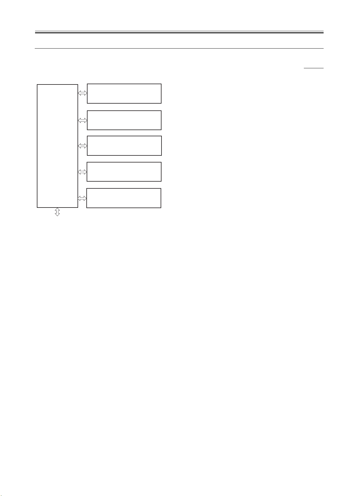
2.1.1 Outline
The functions of this printer can be divided into 6 blocks: the engine control system, laser exposure system, image formation system, pickup and feed
system. fixing and delivery system, external and control system.
Laser exposure system
Image formation system
Engine control
system
Pickup and feed system
Fixing and delivery system
0007-6048
To external devices
F-2-1
External and control system
2-1

HTTP://WWW.FIXCLUB.COM.CN
Chapter 2
2.2 Basic Sequense
2.2.1 Basic Operation Sequence
The operation sequence of this printer is controller by the microprocessor (CPU) on the engine controller PCB. The following diagram shows the purposes
of each periods from power ON until the main motor stops after the completion of printing. See the timing chart.
T-2-1
Period Purpose Remarks
WAIT
(Wait)
STBY
(Standby)
INTR
(Initial rotation)
PRINT
(Print)
LSTR
(Last rotation)
From power-ON until the end
of the main motor initial
rotation.
From the end of the WAIT
period or the LSTR period
until the input of the pick-up
command from the video
controller. Or, from the end of
the LSTR period until powerOFF.
From the input of the print
command from the video
controller until the pick up
solenoid is turned ON
From the end of the initial
rotation until the primary highvoltage is turned OFF.
From the primary high-voltage
is turned OFF until the main
motor stops rotating.
To clean the drum surface
of potential and to clean
the transfer charging
roller.
To keep the printer ready
to print.
To stabilize the
photosensiteive drum
sensitivity in preparation
for printing,Also to clean
the transfer charging
roller.
To form image on the
photosensitive drum
according to the video
signals input from the
interface controller, and
transfers the image to
paper.
Delivers the final page and
cleans the transfer
charging roller.
Toner cartridge in/out detection is
executed.
As soon as the print command is
input from the video controller, the
printer enters the INITIAL
ROTATION period.
0007-9885
2.2.2 Power-on sequence
The following is the sequence from power ON until the engine controller enters STBY mode.
1) Power ON
2) CPU initialization
3) Video interface communication start
4) Residual paper check
Checks the sensors for any residual paper.
5) Main motor initial drive
6) Fixing heater initial drive
Drive the fixing heater so that the fixing unit reaches its targeted temperature of 100 deg C.
7) Scanner motor initial drive
8) High-voltage control
Clean the transfer sharging roller.
9) Failure/ abnormality check
Detects scanner failure, fixing unit failure and door open during the periods mentioned
above.
0007-9887
2-2
HTTP://WWW.FIXCLUB.COM.CN
Chapter 2
2.3 LASER EXPOSURE SYSTEM
2.3.1 Overview/Configuration
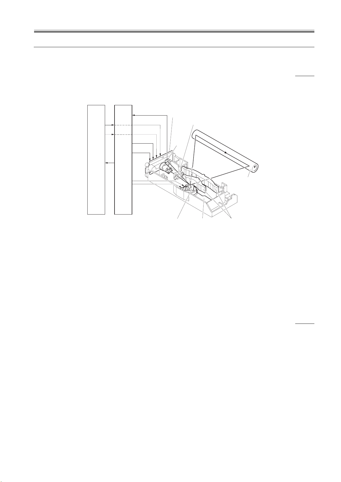
2.3.1.1 Overview
The laser/scanner system serves to form images on the photosensitive drum according to the video signals coming from the video controller, and it consists
of a laser driver PCB, scanner motor, and the like, which are housed inside an assembly as a single unit. The laser/scanner system is controlled by the DC
controller.
The following is a diagram of the laser/scanner system and a description of its sequence of operation.
0008-0084
/BDI
VDO
/VDO
CNT0
CNT1
/BD
/ACC
/DEC
Video
controller
PCB
1. When the print command arrives from the video controller, the engine controller turns on the scanner motor to rotate the 4-facet mirror.
2. When the scanner motor starts to rotate, the engine controller uses the laser control signal to force the laser on. Thereafter, the engine controller starts
to control the rotation of the scanner motor.
3. The engine controller uses the scanner motor speed control signal to make sure that the scanner motor rotates at a specific speed at all times.
4. When the scanner motor reaches a target rotation speed, the video controller sends video signals to the laser driver PCB.
5. The laser driver turns on the laser diode according to these signals.
6. The laser beam moves through a collimating lens and a cylindrical lens to reach the 4-facet mirror rotating at a specific speed.
7. The beam reflected by the 4-facet mirror then moves through the imaging lens and the reflecting mirror arranged in front of the 4-facet mirror and focus
on the surface of the photosensitive drum.
8. When the 4-facet mirror rotates at a specific speed, the laser beam starts to scan the surface of the photosensitive drum at a specific speed.
9. When the photosensitive drum rotates at a specific speed and, at the same time, the laser beam starts to scan the surface of the photosensitive drum at a
specific speed, a static (latent) image starts to form on the surface of the photosensitive drum.
Engine
controller
PCB
Laser driver PCB
Cylindrical lens
BD
sensor
Four-sided
mirror
F-2-2
Scanner motor
Photosensitive
drum
Focusing lens
2.3.2 Controlling the Laser Activation Timing
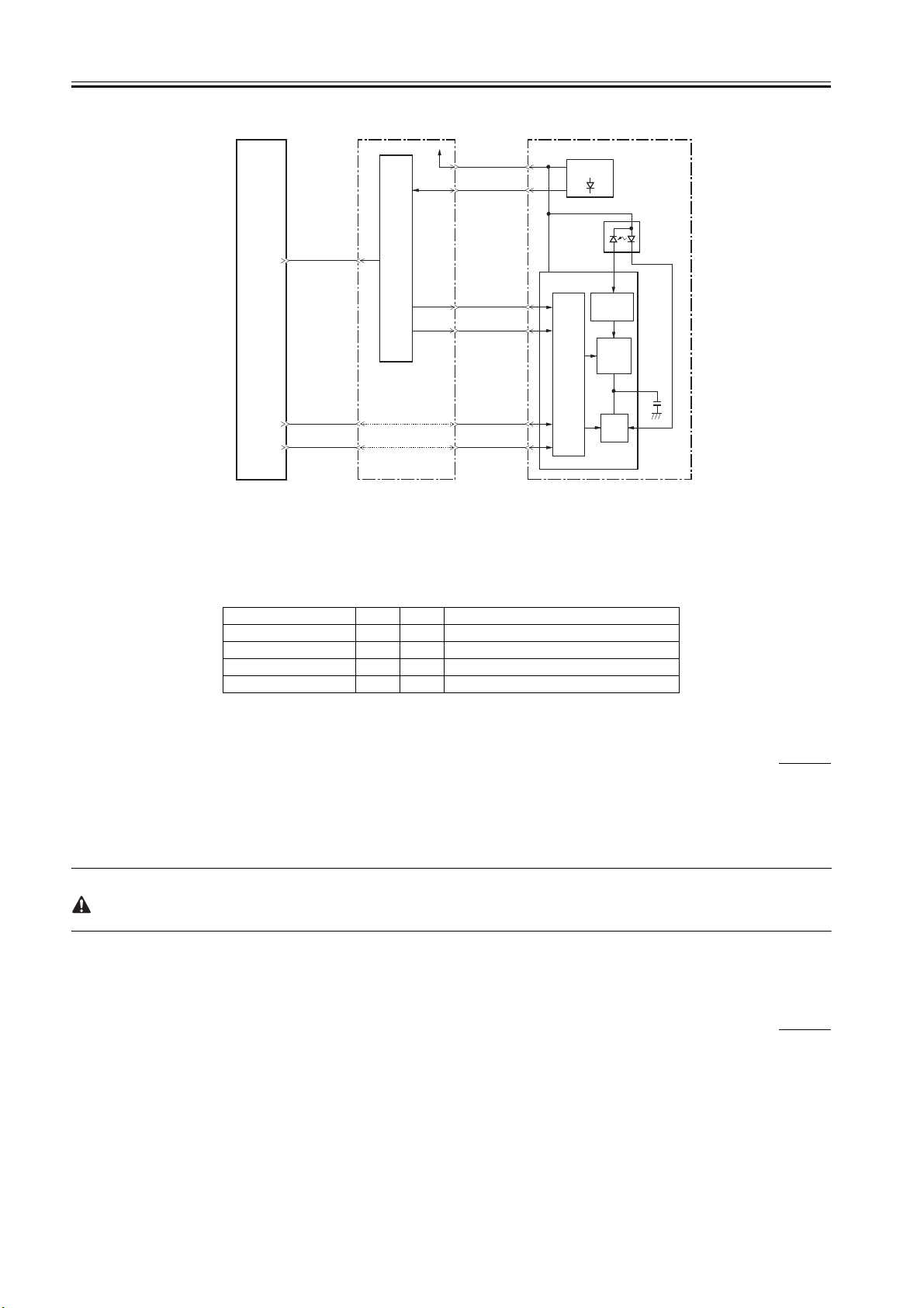
2.3.2.1 Turning On/Off the Laser
The machine controls the activation of the laser according to the laser control signals coming from the engine controller using the laser driver that turns on
and off the laser diode (LD). The following shows the circuit used to control the laser.
0008-0090
2-3
HTTP://WWW.FIXCLUB.COM.CN
Chapter 2
Video controller PCB
/BD
VDO
/VDO
Engine controller PCB
J910-10
-13
-12
IC902
CPU
+5V
J904-8
-9
-5
-6
-3
-2
/BDI
CNT1
CNT0
VDO
/VDO
J801-8
-9
-5
-6
-3
-2
Laser driver PCB
BD sensor
PD
(photodiode)
Laser driver IC
Comparator
Logic
circuit
Sample
hold
circuit
Drive
circuit
LD
(laser diode)
C803
F-2-3
The engine controller is the source of video signals (VDO, /VDO) used for image formation. It is also the source of laser control signals (CNT0, CNT1)
sent to the logic circuit inside the laser driver IC for switching over laser operation modes.
The laser driver CI controls the laser with reference to combinations of CTN0 and CNT1 signals as shown in the following table:
T-2-2
Operating mode CNT0 CNT1 Uses
Discharge L L C803 discharge
Print H L Normal printing
LD APC L H LD APC
LD forced deactivation H H Image masking
2.3.2.2 Horizontal Synchronization Control
The machine controls horizontal synchronization so as to make sure that the image start position is correct in horizontal direction; specifically,
1. The engine controller turns the laser control signal into LD APC mode during an unblanking period (Note).
2. The BD PCB is located in the optical path of the laser beam to detect the beam.
3. When the BD PCB detects the laser beam, it uses the beam to generate the BD input signal (/BDI) for output to the engine controller.
4. In response, the video controller generates the horizontal sync signal (/BD) for output to the interface controller.
5. When the video controller receives the /BD signal, it sends video signals (VDO, /VDO) to the engine controller in a way that the image start position
will be correct in image horizontal direction.
The term "unblanking period" refers to a period of time in which the laser diode is turned on in a non-image area.
0008-0093
2.3.3 Laser Control
2.3.3.1 Auto Photo Current Control
The machine executes auto photo current control to make sure that the laser diode emits light at a specific level of intensity.
APC may be either initial APC (Note 1), which is executed during initial rotation, or interval APC (Note 2), which is executed during printing; however,
both of them are executed in the same way as follows:
1. When the laser control signal (CNT0, CNT1) is in LD APC mode, the laser driver forces the laser diode to go on.
2. The intensify of the light from the laser diode is checked by the photodiode (PD), and its current is converted into an appropriate voltage for comparison
against a reference voltage (equal to the target laser intensity).
3. The laser driver keeps controlling the laser current until the intensity of the light from the laser diode is equivalent to the level of voltage of the target
intensity.
4. Thereafter, when the laser control signal changes to LD forced deactivation mode, the LD is forced to go off, and the laser driver converts the voltage
into a capacitor voltage for retention.
0008-0094
2-4
 Loading...