

Canon K1 Service Manual

Document Insertion Unit-K1
Product Outline
Technology
Periodic Servicing
Parts Replacement/Cleaning Procedure
Adjustment
Installation
Appendix
Service Manual
May 1, 2010
Revision 0
654321

0
Application
This manual has been issued by Canon Inc. for qualied persons to learn technical theory,
installation, maintenance, and repair of products. This manual covers all localities where the
products are sold. For this reason, there may be information in this manual that does not
apply to your locality.
Corrections
This manual may contain technical inaccuracies or typographical errors due to improvements
or changes in products. When changes occur in applicable products or in the contents of
this manual, Canon will release technical information as the need arises. In the event of
major changes in the contents of this manual over a long or short period, Canon will issue
a new edition of this manual.
b
The following paragraph does not apply to any countries where such provisions are
inconsistent with local law.
Trademarks
The product names and company names used in this manual are the registered trademarks
of the individual companies.
Copyright
This manual is copyrighted with all rights reserved. Under the copyright laws, this manual may
not be copied, reproduced or translated into another language, in whole or in part, without the
written consent of Canon Inc.
(C) CANON INC. 2007
0
Caution
Use of this manual should be strictly supervised to avoid disclosure of confidential
information.
b
0
Explanation of Symbols
The following symbols are used throughout this Service Manual.
c
The following rules apply throughout this Service Manual:
Symbols Explanation Symbols Explanation
Check.
Check visually. Insert the claw.
Check the noise. Use the bundled part.
Disconnect the connector.
Connect the connector. Plug the power cable.
Remove the cable/wire
from the cable guide or wire
saddle.
Remove the claw.
Push the part.
Turn on the power.
1. Each chapter contains sections explaining the purpose of specific functions and the
relationship between electrical and mechanical systems with reference to the timing of
operation.
In the diagrams, represents the path of mechanical drive; where a signal
name accompanies the symbol, the arrow indicates the direction of the electric signal.
The expression
the front door, and closing the delivery unit door, which results in supplying the machine
with power.
2. In the digital circuits, '1' is used to indicate that the voltage level of a given signal is
"High", while '0' is used to indicate "Low". (The voltage value, however, differs from
circuit to circuit.) In addition, the asterisk (*) as in "DRMD*" indicates that the DRMD
signal goes on when '0'.
In practically all cases, the internal mechanisms of a microprocessor cannot be checked
in the field. Therefore, the operations of the microprocessors used in the machines
are not discussed: they are explained in terms of from sensors to the input of the DC
controller PCB and from the output of the DC controller PCB to the loads.
The descriptions in this Service Manual are subject to change without notice for product
improvement or other purposes, and major changes will be communicated in the form of
Service Information bulletins.
All service persons are expected to have a good understanding of the contents of this Service
Manual and all relevant Service Information bulletins and be able to identify and isolate faults
in the machine.
"turn on the power" means ipping on the power switch, closing
0
Set the cable/wire to the
cable guide or wire saddle.
Remove the screw.
Tighten the screw.
c

0
d
0
d

0
Contents
Safety Precautions 0-1
Points to Note About Turning Off the Main Power Switch ----------0-2
Notes Before it Works Serving
1 Product Outline 1-1
Features -------------------------------------------------------------------------1-2
Specications
Names of Parts
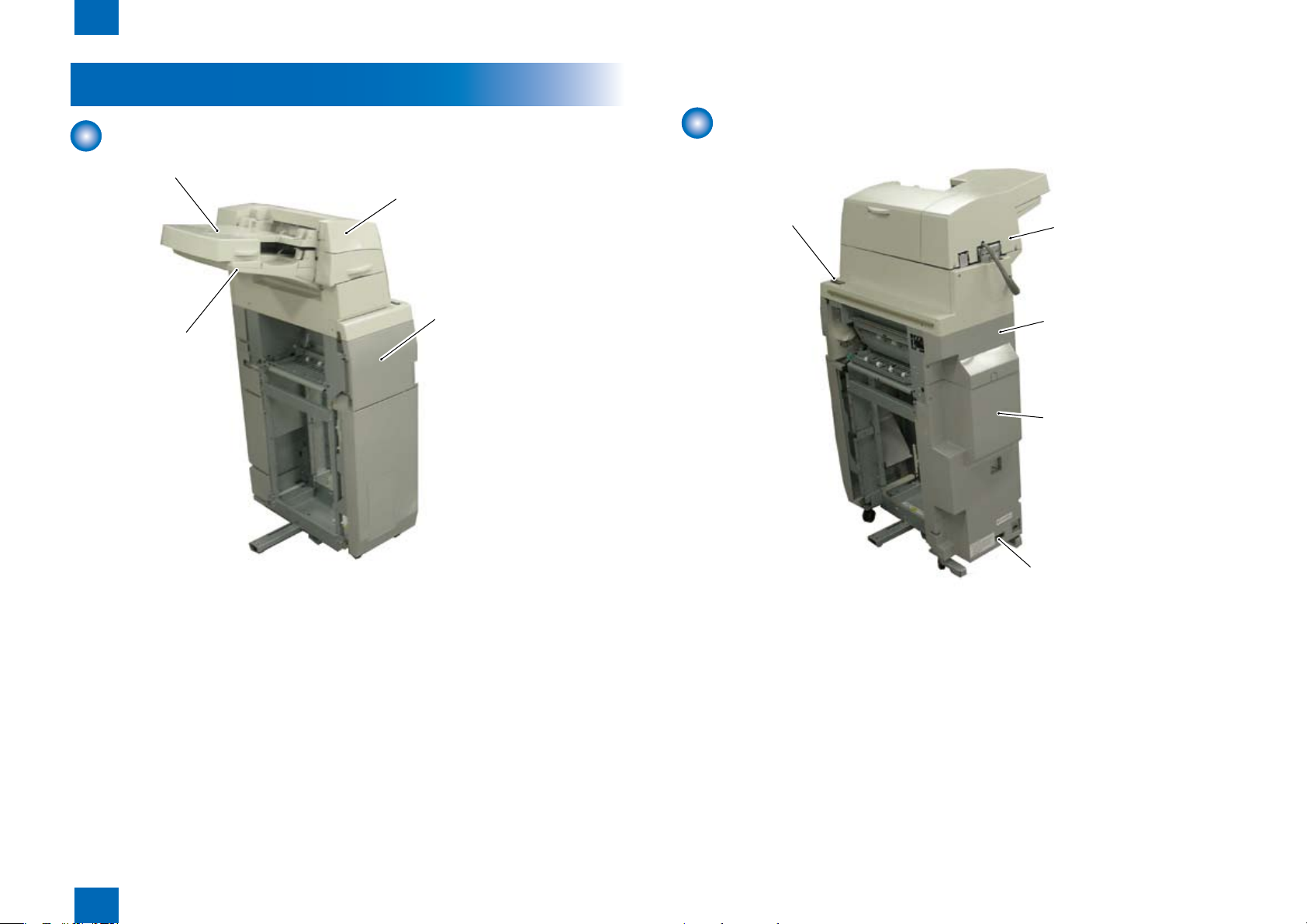
External View(Front) -------------------------------------------------------------- 1-4
External View(Rear) --------------------------------------------------------------- 1-4
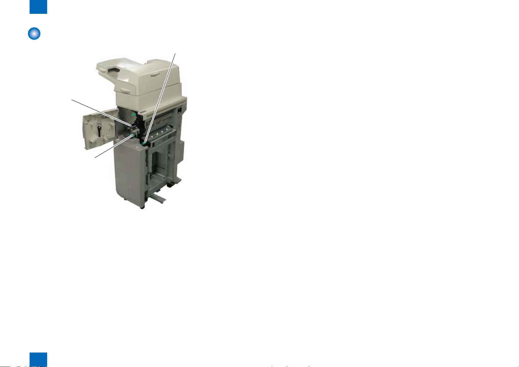
External View(Internal) ----------------------------------------------------------- 1-5
------------------------------------------------------------------1-3
----------------------------------------------------------------1-4
2 Technology 2-1
Basic Conguration -----------------------------------------------------------2-2
Functional Conguration --------------------------------------------------------- 2-2
Overview of Electrical Circuitry ------------------------------------------------- 2-2
Component Conguration ------------------------------------------------------- 2-3
Drive Conguration ---------------------------------------------------------------- 2-4
Basic movement outline ---------------------------------------------------------- 2-4
Various Modes of Control ---------------------------------------------------2-6
Outline of operations -------------------------------------------------------------- 2-6
Jam Detection ---------------------------------------------------------------------2-15
Power Supply ----------------------------------------------------------------------2-17
Work of service --------------------------------------------------------------------2-19
3 Periodic Servicing 3-1
List of Work for Scheduled Servicing ------------------------------------3-2
4 Parts Replacement/Cleaning Procedure 4-1
List Of Parts --------------------------------------------------------------------4-2
---------------------------------------------0-3
e
External / Internal Covers -------------------------------------------------------- 4-2
Consumable Parts Requiring Periodic Replacement and Cleaning
Points --------------------------------------------------------------------------------- 4-3
Motors/PCBs/Others -------------------------------------------------------------- 4-4
List of Sensors ---------------------------------------------------------------------- 4-5
External/Innernal Covers ----------------------------------------------------4-6
Removing the Rear Upper Cover ---------------------------------------------- 4-6
Removing the Rear Lower Cover ---------------------------------------------- 4-7
Removing the Front Upper Cover --------------------------------------------- 4-7
Removing the Front Inner Cover ----------------------------------------------- 4-8
Removing the Inserter Rear Cover -------------------------------------------- 4-9
Changing the Inserter Top Cover Open/Close Angle --------------------- 4-9
Removing the Inserter Front Cover ------------------------------------------4-10
Changing the Middle Guide Open/Close Angle ---------------------------4-10
Changing the Inserter Open Angle -------------------------------------------4-11
Removing the Main Unit ---------------------------------------------------4-12
Removing the Upper Tray Unit ------------------------------------------------4-12
Removing the Lower Tray Unit ------------------------------------------------4-13
Removing the Inserter Pickup Unit -------------------------------------------4-13
Consumable Parts Requiring Periodic Replacement and Cleaning
Points --------------------------------------------------------------------------4-15
Removing the Inserter pickup rollers (upper) ------------------------------4-15
Removing the Inserter pickup roller (lower) --------------------------------4-16
Removing the Inserter separation roller (upper) --------------------------4-16
Removing the Inserter separation roller (lower) ---------------------------4-17
Removing the Inserter feed roller (upper) ----------------------------------4-17
Removing the Inserter feed roller (lower) -----------------------------------4-18
Removing the Inserter torque limiter (upper) ------------------------------4-18
Removing the Inserter torque limiter (lower) -------------------------------4-19
Removing the Inserter electromagnetic clutch (upper) ------------------4-19
Removing the Inserter electromagnetic clutch (lower) ------------------4-20
Removing the Motor --------------------------------------------------------4-21
Removing the Tray Pickup Motor (M1) --------------------------------------4-21
Removing the Drive Switchover Motor (M4) -------------------------------4-22
Removing the Upper Tray Lift Motor (M2) ----------------------------------4-23
Removing the Lower Tray Lift Motor (M3) ----------------------------------4-23
0
e

0
f
Removing the PCB ---------------------------------------------------------4-24
Removing the DC Controller PCB -------------------------------------------4-24
Removing the Upper Tray LED PCB -----------------------------------------4-25
Removing the Lower Tray LED PCB -----------------------------------------4-25
Removing the Sensor ------------------------------------------------------4-27
Removing the Upper tray empty sensor (S9) -----------------------------4-27
Removing the Upper tray width sensor (S10) -----------------------------4-28
Removing the Upper tray last paper sensor (S11) -----------------------4-29
Removing the Low tray empty sensor (S12) -------------------------------4-29
Removing the Low tray width sensor (S13) --------------------------------4-30
Removing the Low tray last paper sensor 1 (S14) -----------------------4-31
Removing the Low tray last paper sensor 2 (S15) -----------------------4-32
5 Adjustment 5-1
Adjustment at Time of Parts Replacement -----------------------------5-2
6 Installation 6-1
Making Pre-installation Checks --------------------------------------------6-2
Checking the Power Supply ----------------------------------------------------- 6-2
Checking the Installation Space ------------------------------------------------ 6-2
Cautions at the Time of Installation -------------------------------------------- 6-3
Checking Bundled Components -------------------------------------------6-4
Unpacking
Unpacking Procedure ------------------------------------------------------------- 6-5
Installation Procedure --------------------------------------------------------6-7
Preparation for Installation on Upstream Connection Machine Side - 6-7
Connecting to Connection Machine ------------------------------------------- 6-8
Height/Inclination Checks -------------------------------------------------------6-10
Connecting the Cables ----------------------------------------------------------6-13
Connecting the Wire saddle ----------------------------------------------------6-14
Making Checks after Completion of Installation Work -------------------6-15
Operation Checks -----------------------------------------------------------------6-15
-----------------------------------------------------------------------6-5
General Circuit Diagram
General Circuit Diagram --------------------------------------------------------- 7-3
-----------------------------------------------------7-3
7 Appendix 7-1
Service Tools -------------------------------------------------------------------7-2
0
f

Safety Precautions
Points to Note About
■
Turning Off the Main
Power Switch
Notes Before it Works
■
Serving

0
Points to Note About Turning Off the Main Power Switch
Points to Note About Turning Off the Main Power Switch
This machine has two switches related to power supply, the Power switch and the breaker.
Turning on the Power switch powers this machine.
The breaker detects an excess current and electric leakage to protect you against an electric shock.
MEMO:
Explain to the customer that the breaker must be checked once or twice a month and the result
must be recorded.
0-2
Points to Note About Turning Off the Main Power Switch
0
0-2

0
Points to Note About Turning Off the Main Power Switch
Notes Before it Works Serving
CAUTION:
At servicing, be sure to turn off the power source according to the specied steps and
disconnect the power plug.
CAUTION:
Do not turn off the power switch when downloading is under way.
Turning off the main power switch while downloading is under way can disable the
machine.
0-3
Points to Note About Turning Off the Main Power Switch
0
0-3

Product Outline
1
Features
■
Specications
■
Names of Parts
■
Product Outline
1

1
Product Outline > Features
Features
A free-standing inserter with a reversal feature, supporting a set of
●
two large tray bins.
Each tray has a capacity of 200 sheets.
●
1-2
Product Outline > Features
1
1-2

1
Product Outline > Specications
Specications
1-3
Item
Paperpickup
method
Paper pickup
mode
Paper types
Paper size
Paper weighing
Loading capacity
Reference
Mixed paper
loading
Operator
console
Display
Size detection
feature
Description Remarks
Auto paper pickup/delivery Upward separation by
a cassette separation
roller
Single-sided automatic reversal
mode supported
Plain paper,recycled paper,colored paper,heavy
paper,coated paper
Uppertray/lowtray/B5to13"×19.2" Feed directi on to
139.7to482.6mm
Width direction to
98.4to330.2mm
52g/m2 to 300g/m2
Loading height:Up to24mm Defined on the basis
Uppertray:200 sheets/lowtray:200sheets
Center reference
No
No
Document loading LED available
Supported Length:Photointerrupters
(Uppertray:1/Lowtray:2)
Width:Slide variable resistors
(Uppertray:1/Lowtray:1)
of 80g/m2 paper
Product Outline > Specications
1
1-3
1
Upper tray
Low tray
Upper cover
Front upper cover
Power switch
Leakage breaker
Rear low cover
Rear upper cover
Rear cover
Product Outline > Names of Parts > External View(Rear)
Names of Parts
1-4
External View(Front)
External View(Rear)
F-1-1F-1-1
F-1-2F-1-2
Product Outline > Names of Parts > External View(Rear)
1
1-4
1
Horizontal feed guide
Jam clearing lever(through-feed unit)
Jam clearing lever
Product Outline > Names of Parts > External View(Internal)
External View(Internal)
1-5
1
F-1-3F-1-3
1-5
Product Outline > Names of Parts > External View(Internal)

Technology
2
Basic Conguration
■
Controls
■
Jam Detection
■
Power Supply
■
Work of service
■
2
Technology
2
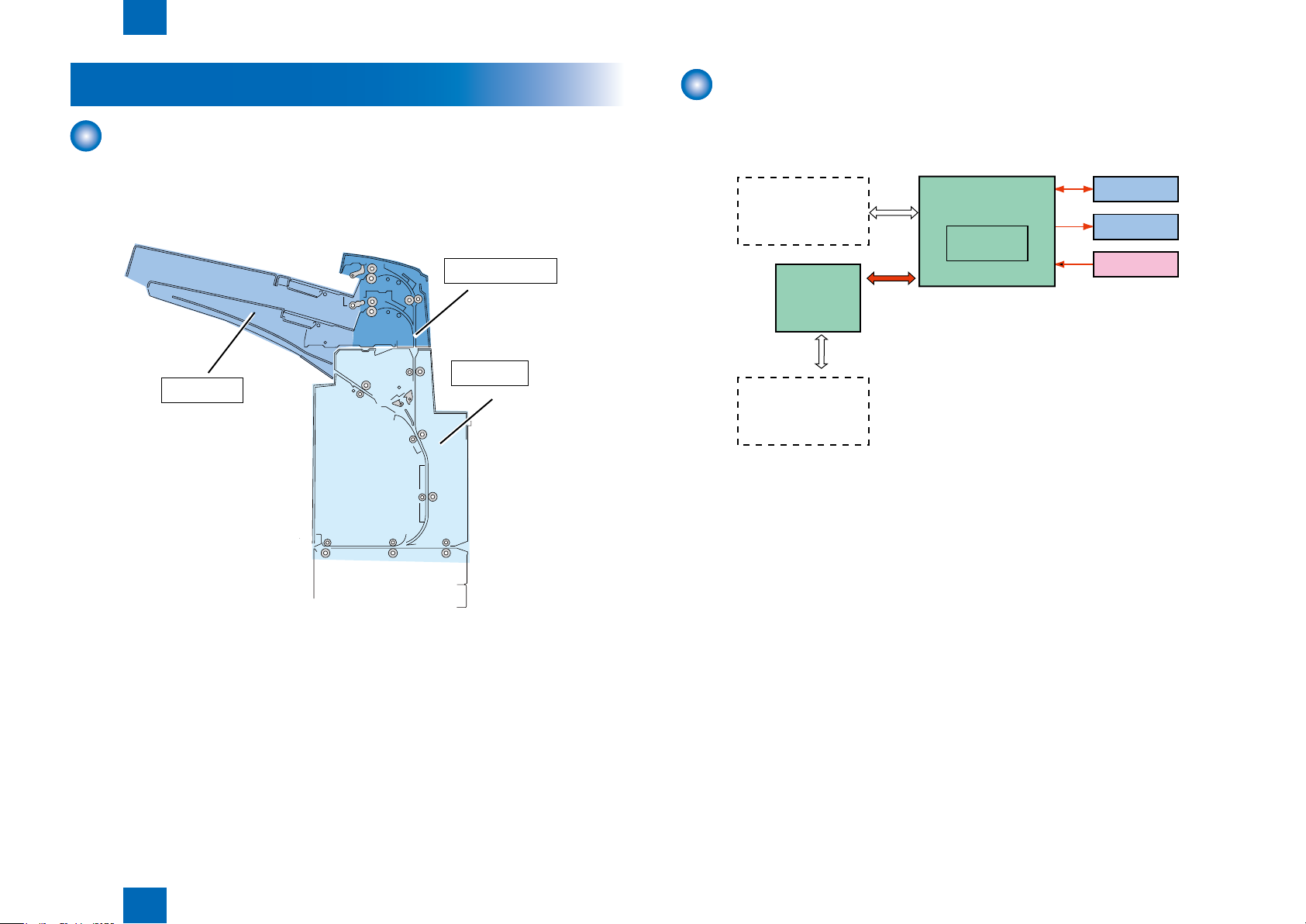
1.tray unit
2.Paper feed unit
3.Feed unit
Fin-AG1/AG2
DC controller PCB
motor
solenoid
sensor
CPU
Arcnet Connection
machin
Arcnet PCB
or
Technology > Basic Conguration > Overview of Electrical Circuitry
2-2
Basic Conguration
Functional Conguration
The components of this fold unit are organized into three major blocks: tray unit,Paper feed
unit and Feed unit.
Overview of Electrical Circuitry
The machine's sequence of operations is controlled by the DC controller PCB.
The DC controller PCB is a CPU used to interpret input signals from sensors and host machine and
generate signals to drive such loads as motors and clutches at such times as programmed in
advance.
F-2-2F-2-2
Technology > Basic Conguration > Overview of Electrical Circuitry
2
F-2-1F-2-1
2-2
2
[1]
[12]
[13]
[14]
[2]
[3]
[4]
[5]
[6]
[7]
[8]
[9]
[10]
[11]
S20
S21
S3
S16
S17
S9
S12
S7
S8
S18
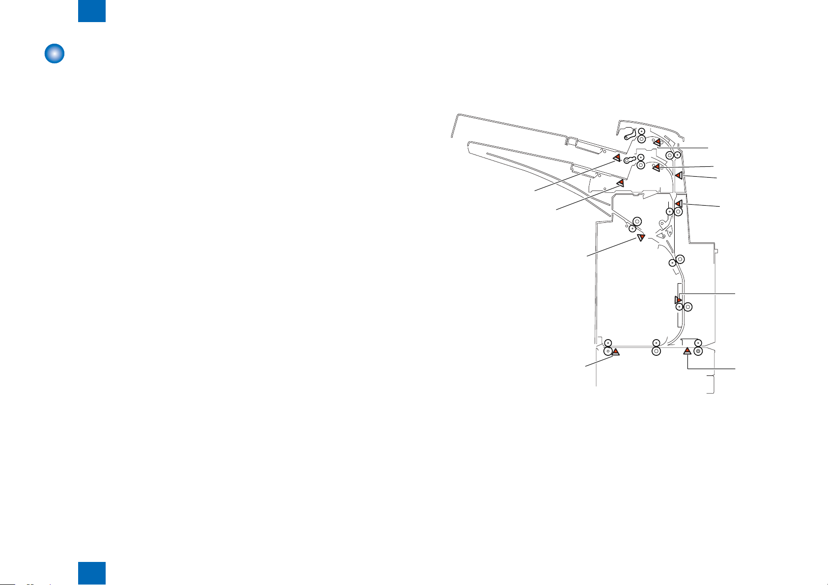
Technology > Basic Conguration > Component Conguration > Sensor Layout
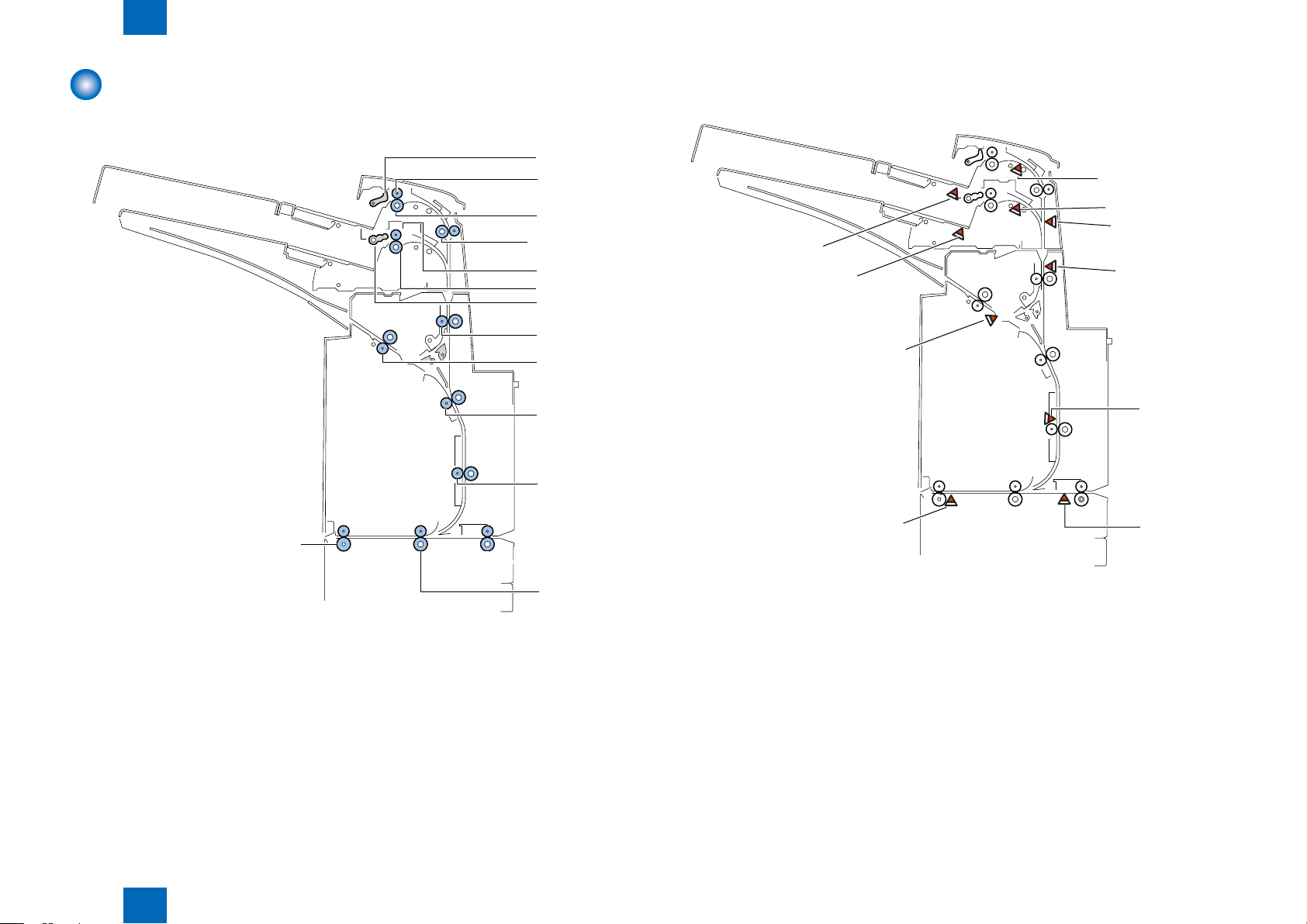
Component Conguration
Roller Layout
■
Sensor Layout
■
It describes only all optical sensors on the feed path.
2-3
[1]Pickup roller(upper) [8]Feed roller1
[2]Feed roller(upper) [9]Reversal roller
[3]Separation roller(upper) [10]Feed roller2
[4]Registration roller [11]Feed roller3
[5]Feed roller(lower) [12]Inlet roller1
[6]Separation roller(lower) [13]Inlet roller2
[7]Pickup roller(lower) [14]Delivery roller
Technology > Basic Conguration > Component Conguration > Sensor Layout
2
F-2-3F-2-3
S3 Upper tray regist sensor
S7 Low tray regist sensor
S8 Middle feed sensor
S9 Upper tray empty sensor
S12 Low tray empty sensor
S16 Reverse timing sensor
S17 Reverse sensor
S18 Reverse entrance sensor
S20 Entrance sensor
S21 Delivery sensor 2
2-3
2
M1 M4
Drive switchover gear
CL1 CL2
SOL1
M3
M2
M6
M5
Technology > Basic Conguration > Basic movement outline > Surface insert operation
2-4
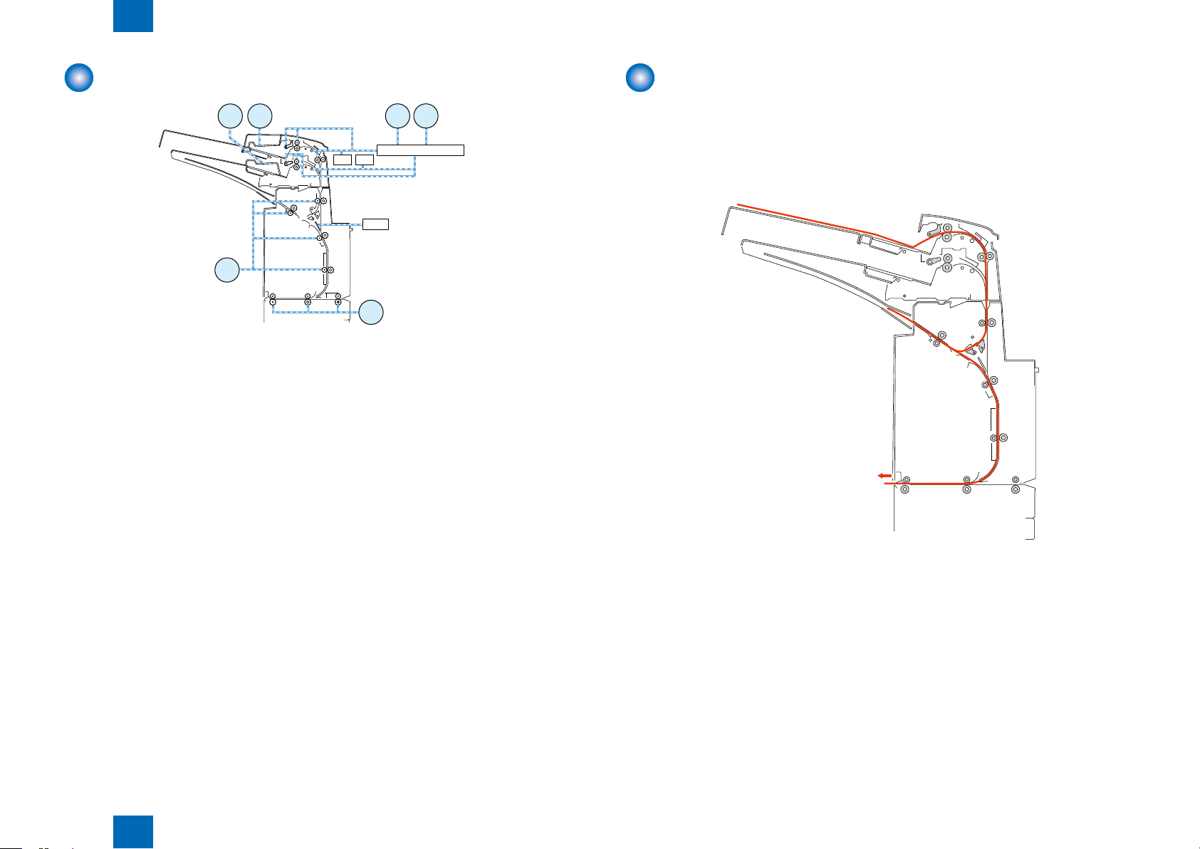
Drive Conguration
M1 Tray Paper feed motor
M2 Upper tray lift motor
M3 Low tray lift motor
M4 Drive switchover motor
M5 Entrance motor 1
M6 Reverse motor
CL1 Uppper tray regist clutch
CL2 Low tray regist clutch
SOL1 Reverse solenoid
F-2-4F-2-4
Basic movement outline
Surface insert operation
■
Transfers the paper loaded in the inserter tray to the downstream equipment so the upper surface
of the paper will face up.
*Paper is fed from atray via a reversing pass to the straight pass.
Technology > Basic Conguration > Basic movement outline > Surface insert operation
2
F-2-5F-2-5
2-4
2
Technology > Basic Conguration > Basic movement outline > Insetrter pickup tray switch operation
2-5
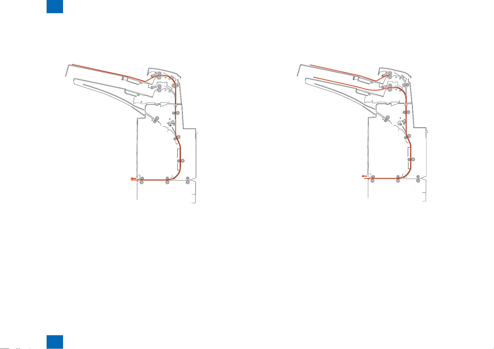
Back insert operation
■
Transfers the paper loaded in the inserter tray to the downstream equipment so the upper surface
of the paper will face down.
*Paper is fed directly to the straight pass.
Insetrter pickup tray switch operation
■
You can have paper fed from either of the two inserter trays chosen at your option.
F-2-6F-2-6
Technology > Basic Conguration > Basic movement outline > Insetrter pickup tray switch operation
2
F-2-7F-2-7
2-5
2
S2
M2
S3
M1
M2
Technology > Various Modes of Control > Outline of operations > Sequence of surface insert operation
Various Modes of Control
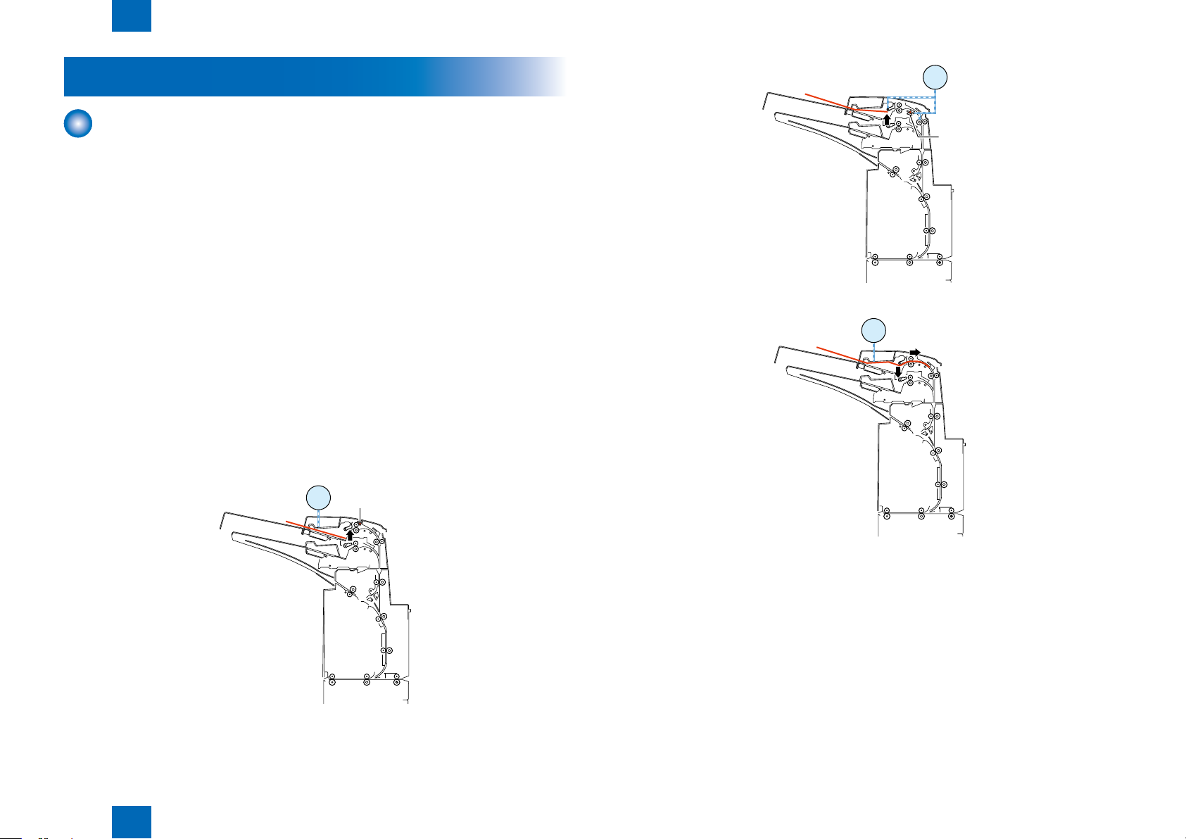
Outline of operations
When a paper feed signal is received from the host machine after paper is loaded in the tray,
the following three sequences of operations are performed:
1.Sequence of surface insert operation
2.Sequence of back insert operation
3.Sequence of inserter pickup tray switch operation
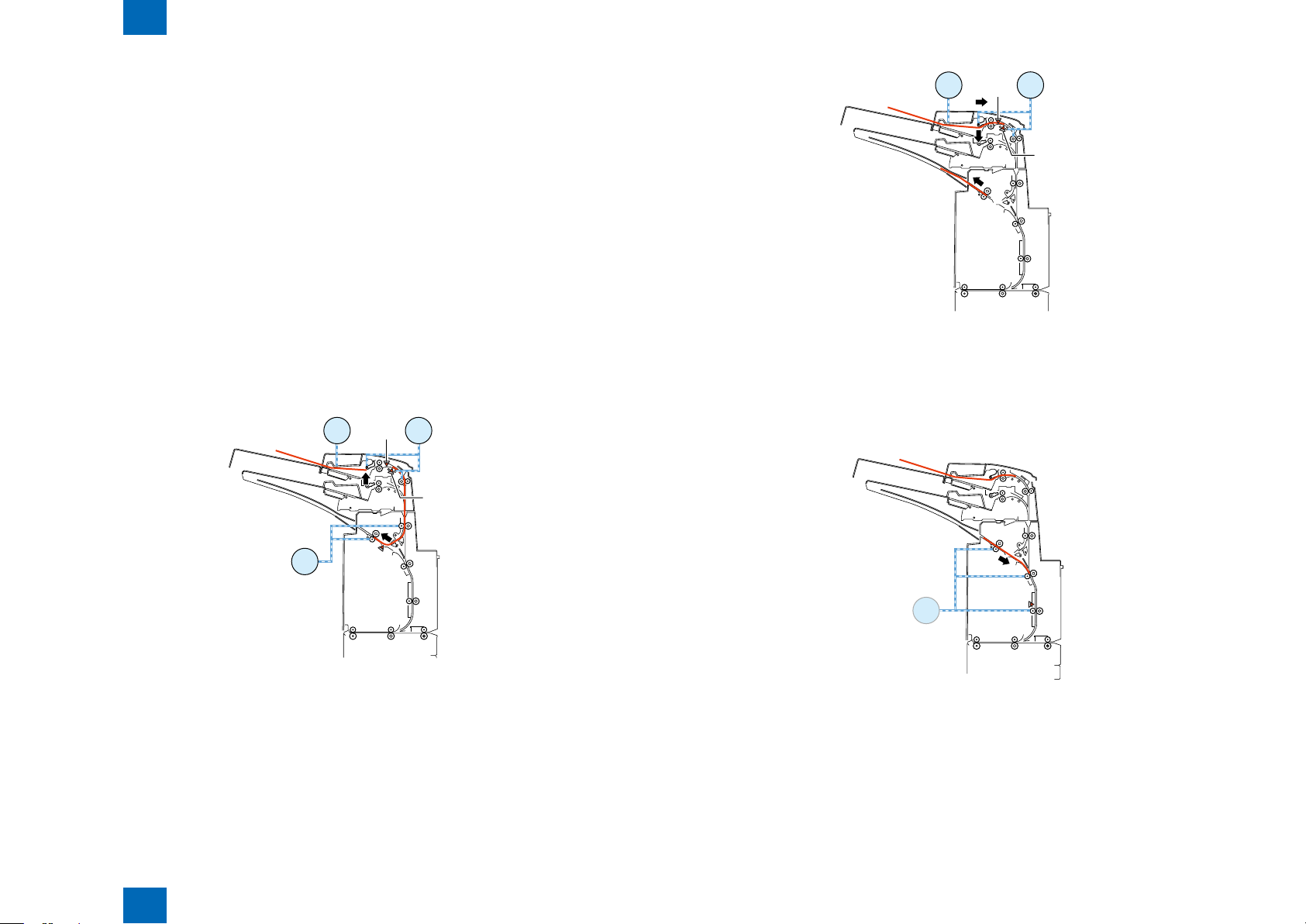
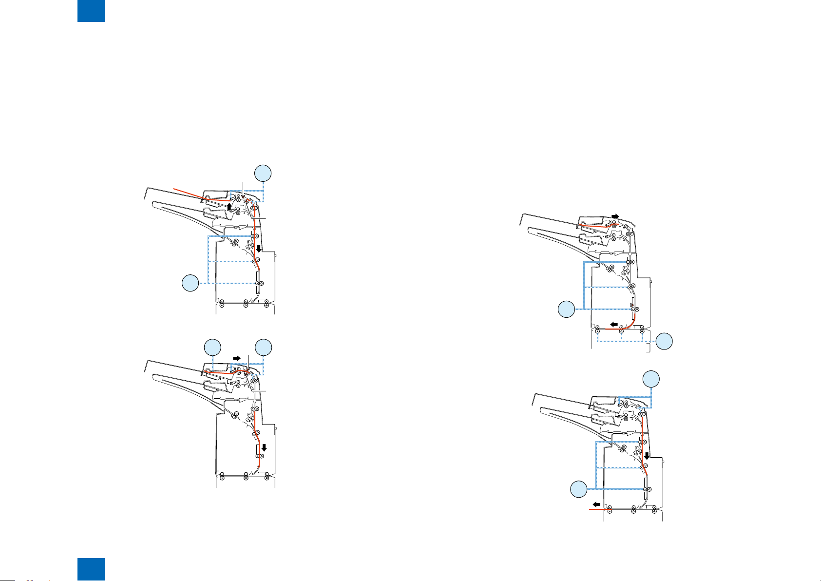
Sequence of surface insert operation
■
2-6
The following operations are performed when two papers are fed from the inserter paper feed unit.
(1) First paper feeding for separation
- The upper tray lift motor turns in the reverse direction at a speed of 533 pps to move the paper feed
tray upward.
- The upper tray pick sensor turns on to stop the upper tray lift motor.
- For plain paper, the tray paper feed motor turns in the reverse direction at a speed of 500 mm/s
to start separating the paper in the tray. For thick paper, the tray paper feed motor turns in the
reverse direction at a speed of 250 mm/s to start separating the paper in the tray.
- For the upper tray, the tray paper feed motor stops when the paper has been fed 14.7 [mm] since
the registration sensor turned on. For the lower tray, the tray paper feed motor stops when the
paper has been fed 19.1 mm since the registration sensor turned on.
- The upper tray lift motor turns in the normal direction at a speed of 533 pps to move the paper feed
tray 9 pls downward.
F-2-9F-2-9
F-2-10F-2-10
F-2-8F-2-8
Technology > Various Modes of Control > Outline of operations > Sequence of surface insert operation
2
2-6
2
S3
S17
S2
M6
M2
M1
M2
S3
S2
M1
M6
S16
Technology > Various Modes of Control > Outline of operations > Sequence of surface insert operation
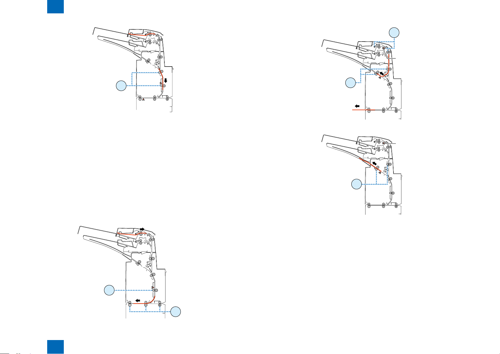
(2) First paper feeding for reversal
- The tray feed motor turns in the normal direction at a speed of 400 mm/s and the reverse motor
turns in the normal direction at a speed of 400 mm/s to start feeding the paper to the reversal
standby position.
- For the upper tray, the tray paper feed motor stops when the paper has been fed 64.6 [mm] since
the registration sensor turned off. For the lower paper feed tray, the tray paper feed motor stops
when the paper has been fed 10.3 mm since the registration sensor turned off.
- The reversal motor stops when the paper has been fed 19.2 mm since the reverse sensor turned
off.
(3) Second paper feeding for separation
- After the paper feed motor stops as mentioned above, the upper tray lift motor turns in the reverse
direction at a speed of 533 pps to move the paper feed tray upward.
- The upper tray pick sensor turns on to stop the upper tray lift motor.
- For plain paper, the tray paper feed motor turns at a speed of 500 mm/s to start separating the
paper in the tray. For thick paper, the motor turns in the reverse direction at a speed of 250 mm/s
to start separating the paper in the tray.
- For the upper tray, the tray paper feed motor stops when the paper has been fed 14.7 [mm] since
the registration sensor turned on. For the lower tray, the tray paper feed motor stops when the
paper has been fed 19.1 mm since the registration sensor turned on.
- The upper tray lift motor turns in the normal direction at a speed of 533 pps to move the paper feed
tray 9 pls downward.
2-7
F-2-12F-2-12
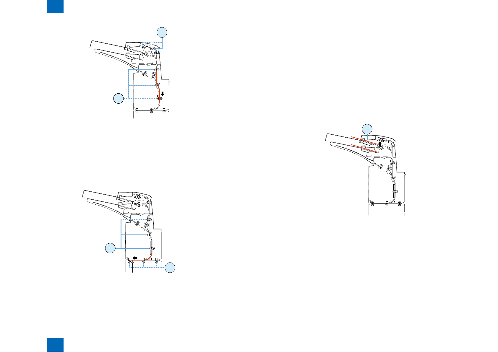
(4) First paper feeding to standby position
- The reverse motor turns in the reverse direction at a speed of 800 mm/s to start feeding the paper
to the standby position.
- When the paper has been fed 51.2 mm since the reverse timing sensor turned on, the reverse
motor stops.
- When the paper has been fed 12.3 mm since the delivery sensor 2 turned on, an Eject signal is
sent.
F-2-11F-2-11
Technology > Various Modes of Control > Outline of operations > Sequence of surface insert operation
2
F-2-13F-2-13
2-7
2
M6
S16
S21
M6
S16
M5
S3
S17
M6
M1
S3
S17
M6
Technology > Various Modes of Control > Outline of operations > Sequence of surface insert operation
F-2-14F-2-14
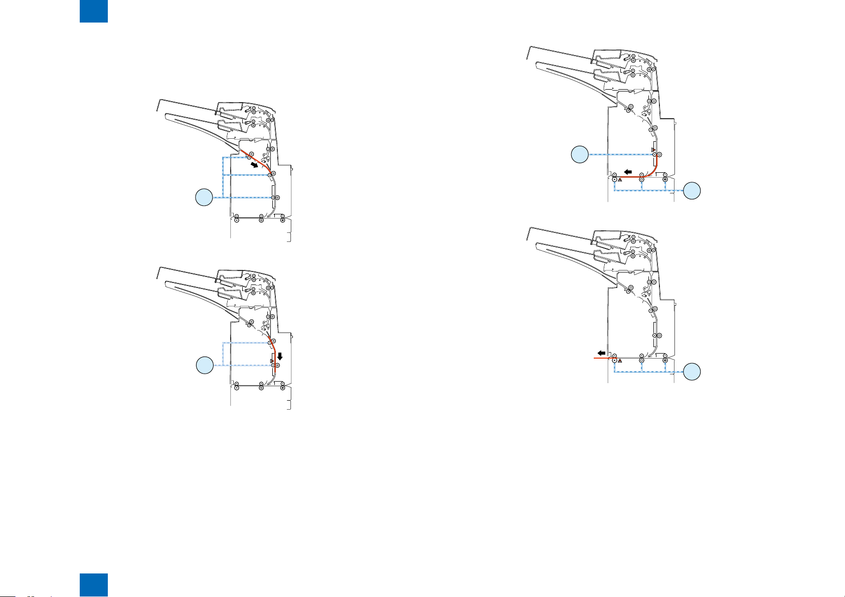
(5) First paper feeding to horizontal feed block
- When an Entry signal for the rst paper is received, the entrance motor 1 turns in the reverse
direction at the same speed as that of the motor in the host machine and the reverse motor turns
in the reverse direction at the same speed as that of the motor in the host machine, thus feeding
the paper to the horizontal feed block.
- When the paper has been fed 51.2 mm since the reverse timing sensor was turned off, the reverse
motor stops.
(6) Second paper feeding for reversal
- After the reverse feed motor stops as mentioned above, the tray feed motor turns in the normal
direction at a speed of 400 mm/s and the reverse motor turns in the normal direction to start
feeding the paper to the standby position.
- In case of paper feed from the upper tray, the tray paper feed motor stops when the paper has been
fed 64.6 mm since the registration sensor turned off. In case of paper feed from the lower tray, the
tray paper feed motor stops when the paper has been fed 10.3 mm since the registration sensor
turned off.
- The reverse motor stops when the paper has been fed 19.2 mm since the reverse sensor turned
off.
2-8
F-2-16F-2-16
F-2-17F-2-17
Technology > Various Modes of Control > Outline of operations > Sequence of surface insert operation
2
F-2-15F-2-15
2-8
2
M6
M6
S16
M6
S16
M5
S21
M5
S21
Technology > Various Modes of Control > Outline of operations > Sequence of surface insert operation
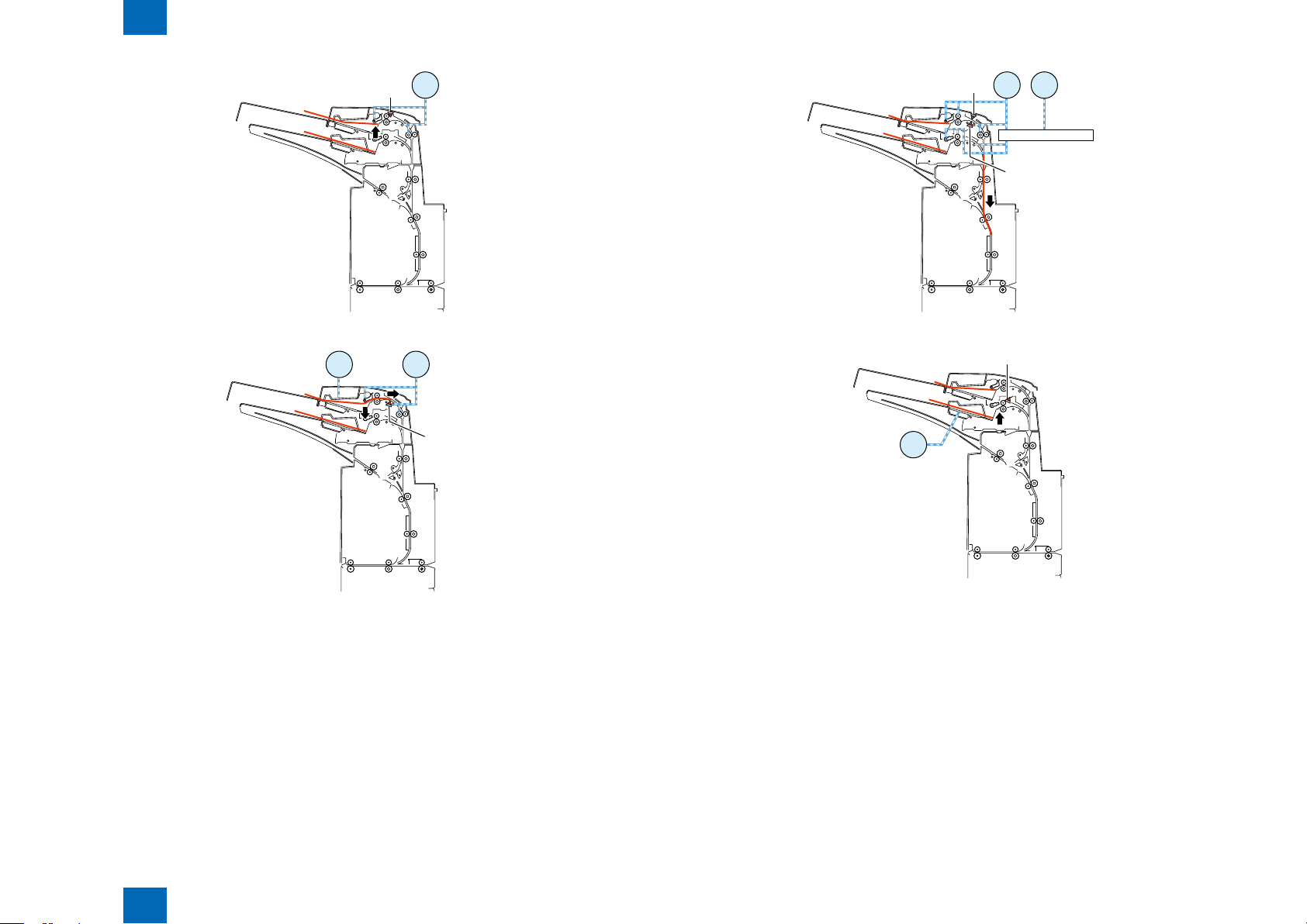
(7) Second paper feeding to standby position
- The reverse motor turns in the reverse direction at a speed of 800 mm/s to start feeding the paper
to the standby position.
- The reverse motor stops when the paper has been fed 51.2 mm since the reverse timing sensor
turned on.
F-2-18F-2-18
2-9
F-2-20F-2-20
(8) Second paper feeding to horizontal feed block
F-2-19F-2-19
- When an Entry signal for the second paper is received, the time specied to allocate a the pace
between the rst and second papers is taken, the entrance motor 1 turns in the reverse direction
at the same speed as that of the motor in the host machine, and the reverse motor turns in the
reverse direction at the same speed as that of the motor in the host machine, thus feeding the
paper to the horizontal feed block.
- An Eject signal is sent when the paper has been fed 12.3 mm since the delivery sensor 2 turned on.
Technology > Various Modes of Control > Outline of operations > Sequence of surface insert operation
2
F-2-21F-2-21
2-9
2
S2
M2
S3
M2 M1
M2
S3
M1
Technology > Various Modes of Control > Outline of operations > Sequence of back insert operation
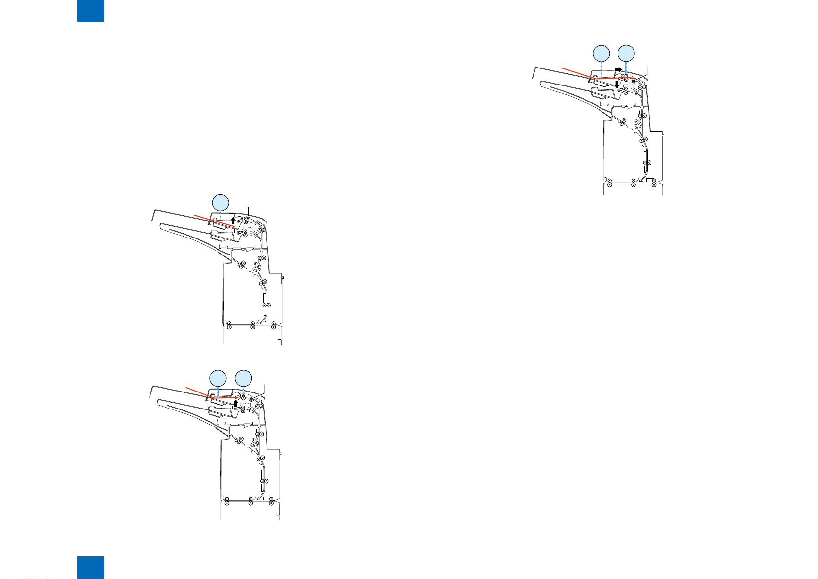
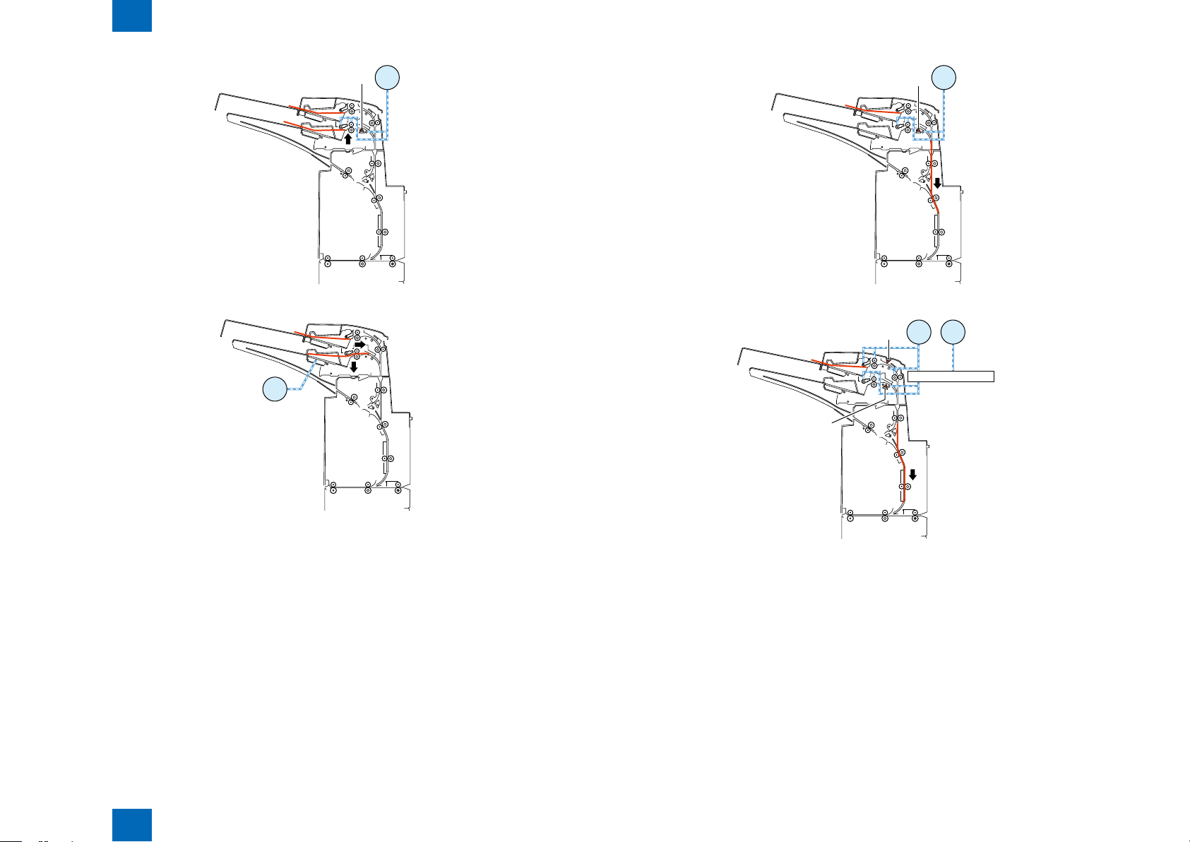
Sequence of back insert operation
■
The following operations are performed when two papers are fed from the inserter paper feed unit.
(1) First paper feeding for separation
- The upper tray lift motor turns in the reverse direction at a speed of 533 pps to move the paper feed
tray upward.
- The upper tray pick sensor turns on to stop the upper tray lift motor.
- For plain paper, the tray paper feed motor turns in the reverse direction at a speed of 500 mm/s
to start separating the paper in the tray. For thick paper, the tray paper feed motor turns in the
reverse direction at a speed of 250 mm/s to start separating the paper in the tray.
- For the upper tray, the tray paper feed motor stops when the paper has been fed 14.7 [mm] since
the registration sensor turned on. For the lower tray, the tray paper feed motor stops when the
paper has been fed 19.1 mm since the registration sensor turned on.
- The upper tray lift motor turns in the normal direction at a speed of 533 pps to move the paper feed
tray 9 pls downward.
2-10
F-2-24F-2-24
(2)First paper feeding to standby position
- The tray paper feed motor turns in the normal direction at a speed of 800 mm/s to start feeding the
paper to the standby position.
- In case of paper feed from the upper tray, the tray paper feed motor stops when the paper has been
fed 64.6 mm since the registration sensor turned off. In case of paper feed from the lower tray, the
tray paper feed motor stops when the paper has been fed 10.3 mm since the registration sensor
turned off.
- The reverse motor stops when the paper has been fed 51.2 mm since the reverse timing sensor
turned on.
2
F-2-22F-2-22
F-2-23F-2-23
Technology > Various Modes of Control > Outline of operations > Sequence of back insert operation
2-10
2
S2
S3
M6
M1
S2
S3
M2
M1
S16
M6
M5
M6
M1
Technology > Various Modes of Control > Outline of operations > Sequence of back insert operation
2-11
(3) Second paper feeding for separation
- After the paper feed motor stops as mentioned above, the upper tray lift motor turns in the reverse
direction at a speed of 533 pps to move the paper feed tray upward.
- The upper tray pick sensor turns on to stop the upper tray lift motor.
- For plain paper, the tray paper feed motor turns at a speed of 500 mm/s to start separating the
paper in the tray. For thick paper, the motor turns in the reverse direction at a speed of 250 mm/s
to start separating the paper in the tray.
- For the upper tray, the tray paper feed motor stops when the paper has been fed 14.7 mm since the
registration sensor turned on. For the lower tray, the tray paper feed motor stops when the paper
has been fed 19.1 mm since the registration sensor turned on.
- The upper tray lift motor turns in the normal direction at a speed of 533 pps to move the paper feed
tray 9 pls downward.
F-2-25F-2-25
(4) First paper feeding to horizontal feed block
- When an Entry signal for the rst paper is received, the entrance motor 1 turns in the reverse
direction at the same speed as that of the motor in the host machine and the reverse motor turns
in the reverse direction at the same speed as that of the motor in the host machine, thus feeding
the paper to the horizontal feed block.
- The reverse motor stops when the paper has been fed 51.2 mm since the reverse timing sensor
was turned off.
- An Eject signal is sent when the paper has been fed 12.3 mm since the delivery sensor 2 turned on.
(5) Second paper feeding to standby position
- After the reverse feed motor stops as mentioned above, the tray paper feed motor turns in the
normal direction at a speed of 800 mm/s to start feeding the paper to the standby position.
- In case of paper feed from the upper tray, the tray paper feed motor stops when the paper has been
fed 64.6 mm since the registration sensor turned off. In case of paper feed from the lower tray, the
tray paper feed motor stops when the paper has been fed 10.3 mm since the registration sensor
turned off.
- The reverse motor stops when the paper has been fed 51.2 mm since the reverse timing sensor
turned on.
F-2-26F-2-26
Technology > Various Modes of Control > Outline of operations > Sequence of back insert operation
2
F-2-27F-2-27
F-2-28F-2-28
2-11
2
M6
M1
S16
S3
S21
M6
M5
S2
M2
Technology > Various Modes of Control > Outline of operations > Sequence of inserter pickup tray switch operation
F-2-29F-2-29
(6) Second paper feeding to horizontal feed block
- When an Entry signal for the second paper is received, the time specied to allocate a the pace
between the rst and second papers is taken, the entrance motor 1 turns in the reverse direction
at the same speed as that of the motor in the host machine, and the reverse motor turns in the
reverse direction at the same speed as that of the motor in the host machine, thus feeding the
paper to the horizontal feed block.
- The reverse motor stops when the paper has been fed 51.2 mm since the reverse timing sensor
was turned off.
- An Eject signal is sent when the paper has been fed 12.3 mm since the delivery sensor 2 turned on.
2-12
Sequence of inserter pickup tray switch operation
■
This section describes switching of the upper tray to the lower tray that take place when two papers
are fed to the upper tray and one paper is fed to the lower tray respectively from the inserter paper
feed unit.
(1) Upper tray paper feeding for separation
- The upper tray lift motor turns in the reverse direction at a speed of 533 pps to move the paper feed
tray upward.
- The upper tray pick sensor turns on to stop the upper tray motor.
- For plain paper, the tray paper feed motor turns in the reverse direction at a speed of 500 mm/s to
start separating the paper in the upper tray. For thick paper, the tray paper feed motor turns in the
reverse direction at a speed of 250 mm/s to start separating the paper in the upper tray.
- The tray paper feed motor stops when the paper has been fed 14.7 mm since the upper tray
registration sensor turned on.
- The tray lift motor turns in the normal direction at a speed of 533 pps to move the paper feed tray 9
pls downward.
F-2-30F-2-30
Technology > Various Modes of Control > Outline of operations > Sequence of inserter pickup tray switch operation
2
F-2-31F-2-31
2-12
2
S2
M1
M1M2
S3
Drive switchover gear
M1 M4
S3
S1
S6
M3
Technology > Various Modes of Control > Outline of operations > Sequence of inserter pickup tray switch operation
2-13
F-2-32F-2-32
F-2-33F-2-33
(2) Upper tray paper feeding to standby position or upper tray paper feeing for reversal
* The gure shows feeding of the paper to the standby position.
- In case of reverse side insertion, the paper is fed to the standby position following the right side
insertion sequence. In case of reverse side insertion, the paper is fed to the standby position
following the reverse side insertion sequence.
(3) Switching between paper feed trays
- The tray paper feed motor stops when the paper has been fed 64.6 mm since the trailing edge of
the paper in the upper tray has turned off the registration sensor.
At this time, the drive switchover motor turns in the normal direction at a speed of 533 pps.
- The drive switchover motor stops when the paper has been fed 32 pls (2mm) since the drive
switchover HP sensor turned on.
F-2-34F-2-34
F-2-35F-2-35
(4) Lower tray paper feeding for separation
- The lower tray motor turns in the reverse direction at a speed of 533 pps to move the paper feed
tray upward.
- The lower tray pick sensor turns on to stop the lower tray lift motor.
- For plain paper, the tray paper feed motor turns in the reverse direction at a speed of 500 mm/s to
start separating the paper in the lower tray. For thick paper, the tray paper feed motor turns in the
reverse direction at a speed of 250 mm/s to start separating the paper in the lower tray.
- The tray paper feed motor stops when the paper has been fed 19.1 mm since the lower tray
registration sensor turned on.
- The lower tray lift motor turns in the normal direction at a speed of 533 pps to lower the paper feed
tray 9 pls downward.
Technology > Various Modes of Control > Outline of operations > Sequence of inserter pickup tray switch operation
2
2-13
2
S7
M1
M3
S7
M1
M1 M4
S7
S1
Drive switchover gear
Technology > Various Modes of Control > Outline of operations > Sequence of inserter pickup tray switch operation
2-14
F-2-36F-2-36
F-2-37F-2-37
(5) Lower tray paper feeding to standby position or lower tray paper feeing for reversal
* The gure shows feeding of the paper to the standby position.
- In case of reverse side insertion, the paper is fed to the standby position following the right side
insertion sequence. In case of reverse side insertion, the paper is fed to the standby position
following the reverse side insertion sequence.
(6) Switching between paper feed trays
- The tray paper feed motor stops when the paper has been fed 10.3 mm since the trailing edge of
the paper in the lower tray has turned off the registration sensor.
At this time, the drive switchover motor turns in the reverse direction at a speed of 533 pps.
- The drive switchover motor stops when the paper has been fed 275 pls since the drive switchover
HP sensor turned off.
F-2-38F-2-38
F-2-39F-2-39
(7) Upper tray paper feeding for separation.
(1) Same as the Description is omitted.
Technology > Various Modes of Control > Outline of operations > Sequence of inserter pickup tray switch operation
2
2-14
2
S20
S21
S3
S16
S17
S9
S12
S7
S8
S18
Technology > Various Modes of Control > Jam Detection > Jam Type
Jam Detection
Overview
■
The following paper sensors are used to detect whether paper is present and whether paper
is fed normally.
S3 Upper tray registration sensor
S7 Lower tray registration sensor
S8: Middle feed sensor
S9: Upper tray empty sensor
S12: Lower tray empty sensor
S16: Reverse timing sensor
S17: Reverse sensor
S18: Reverse entrance sensor
S20: Entrance sensor
S21: Delivery sensor 2
2-15
Technology > Various Modes of Control > Jam Detection > Jam Type
2
Jam Type
■
F-2-40F-2-40
2-15
 Loading...