


Dec 3 2004
Portable Manual
iR C3200 Series
iR C3220N PRT


Application
This manual has been issued by Canon Inc. for qualified persons to learn technical theory, installation, maintenance, and
repair of products. This manual covers all localities where the products are sold. For this reason, there may be
information in this manual that does not apply to your locality.
Corrections
This manual may contain techni cal inaccura cies or typograp hical errors due to improvem ents or changes in products.
When changes occur in applicable products or in the contents of this manual, Canon will release technical information
as the need arises. In the event of major changes in the contents of this manual over a long or short period, Canon will
issue a new edition of this manual.
The following paragraph does not apply to any countries where such provisions are inconsistent with local law.
Trademarks
The product names and company names used in this manual are the registered trademarks of the individual companies.
Copyright
This manual is copyrighted with all rights reserved. Under the copyright laws, this manual may not be copied,
reproduced or translated into another language, in whole or in part, without the written consent of Canon Inc.
COPYRIGHT © 2001 CANON INC.
Printed in Japan
Caution
Use of this manual should be strictly supervised to avoid disclosure of confidential information.

Introduction
Symbols Used
This documentation uses the following symbols to indicate special information:
Symbol Description
Indicates an item of a non-specific nature, possibly classified as Note, Caution, or Warning.
Indicates an item requiring care to avoid electric shocks.
Indicates an item requiring care to avoid combustion (fire).
Indicates an item prohibiting disassembly to avoid electric shocks or problems.
Indicates an item requiring disconnection of the power plug from the el ect r ic outlet.
Indicates an item intende d to provide notes assisting the understanding of the topic in question.
Indicates an item of reference assisting the understanding of the topic in question.
Provides a description of a service mode.
Provides a description of the nature of an error indication.
Memo
REF.

Introduction
The following rules apply throughout this Service Manual:
1. Each chapter contains sections exp laining the pu rpose of specific fun ctions and the rel ationship between electrical
and mechanical systems with reference to the timing of operation.
In the diagrams, represents the path of mechanical drive; where a signal name accompanies the symbol ,
the arrow indicates the direction of the electric signal.
The expression "turn on the power" means flipping on the power switch, closing the front do or, and closing the
delivery unit door, which resu lts in supplying the machine with power.
2. In the digital circuits, '1'is used to indicate that the voltage level of a given signal is "High", while '0' is used to
indicate "Low".(The voltage value, however, differs from circuit to circuit.) In addition, the asterisk (*) as in
"DRMD*" indicates that the DRMD signal goes on when '0'.
In practically all cases, the internal mechanisms of a microprocessor cannot be checked in the field. Therefore, the
operations of the microprocesso rs used in the machines are not discusse d: they are explained in terms of from
sensors to the input of the DC con troller PCB and from the output of the DC controller PCB to the loads.
The descriptions in this Service Manual are subject to change without notice for product improvement or other
purposes, and major changes will be communicated in the form of Service Information bulletins.
All service persons are expected to have a good understanding of the contents of this Service Manual and all relevant
Service Information bulletins and be able to identify and isolate faults in the machine."


Contents
Contents
Chapter 1 Maintenance and Inspection
1.1 Periodically Replaced Parts ...............................................................................................................................1-1
1.1.1Periodically Replaced Parts .........................................................................................................................1-1
1.1.2Reader Unit/Color Image Reader-C1 ..........................................................................................................1-1
1.1.3Printer Unit ..................................................................................................................................................1-1
1.2 Durables and Consumables ...............................................................................................................................1-2
1.2.1Outline .........................................................................................................................................................1-2
1.2.2Reader Unit/Color Image Reader-C1 ..........................................................................................................1-2
1.2.3Printer Unit ..................................................................................................................................................1-2
1.3 Scheduled Servicing Basic Procedure ...............................................................................................................1-4
1.3.1Scheduled Servicing (Reader Unit) ............................................................................................................. 1-4
1.3.2Scheduled Servicing (Printer Unit) .............................................................................................................1-6
Chapter 2 Standards and Adjustments
2.1 Image Adjustments ............................................................................................................................................2-1
2.1.1Standards for Image Position .................................. ...................................... ..............................................2-1
2.1.2Checking the Image Position .......................................................................................................................2-1
2.1.3Adjusting the Left/Right Margin (Cassette) ................................................................................................2-2
2.1.4Adjusting the Left/Right Margin (Manual Feed Tray) ................................................................................2-3
2.1.5Adjusting the Left/Right Margin (Side Paper Deck) ...................................................................................2-3
2.1.6Duplex Unit ................................................................................................................................................. 2-4
2.2 Scanning System ...............................................................................................................................................2-5
2.2.1After Replacing the Scanning Lamp ...........................................................................................................2-5
2.2.2After Replacing the Copyboard Glass .........................................................................................................2-5
2.2.3After Replacing the CCD Unit ....................................................................................................................2-5
2.3 Laser Exposure System .....................................................................................................................................2-6
2.3.1After Replacing the Laser Unit ...................................................................................................................2-6
2.4 Image Formation System ...................................................................................................................................2-7
2.4.1After Replacing the Drum Unit ................................................................................................................... 2-7
2.4.2After Replacing the Transfer Unit ...............................................................................................................2-7
2.4.3After Replacing the Pattern Reading Unit ...................................................................................................2-7
2.5 Fixing System ....................................................................................................................................................2-8
2.5.1After Disassembling the Fixing Unit ...........................................................................................................2-8
2.6 Electrical Components ...................................................................................................................................... 2-9
2.6.1When Replacing the Reader Controller PCB ..............................................................................................2-9
2.6.2When Replacing the DC Controller PCB ....................................................................................................2-9
2.6.3When Replacing the Main Controller PCB (main) ...................................................................................2-10
2.6.4When Replacing the Main Controller PCB (sub) ......................................................................................2-10
2.6.5When Replacing the SRAM PCB .............................................................................................................2-10
2.6.6When Replacing the HDD .........................................................................................................................2-11
2.6.7When Replacing the Power Supply PCB ..................................................................................................2-11
2.7 Pickup/Feeding System ...................................................................................................................................2-12
2.7.1Adjusting the Horizontal Registration When Replacing the Pickup Cassette ...........................................2-12
2.7.2Adjusting the Horizontal Registration When Replacing the Duplex Unit ................................................2-13

Contents
Chapter 3 Error Code
3.1 Error Code Details .............................................................................................................................................3-1
3.1.1Error Code Details Table .............................................................................................................................3-1
Chapter 4 User Mode Items
4.1 Common Settings ...............................................................................................................................................4-1
4.2 Timer Settings ....................................................................................................................................................4-3
4.3 Adjustments and Cleaning ..................................................................................... ............................................4-4
4.4 Report Generation ..............................................................................................................................................4-5
4.5 System Control Settings ................................................................... .................................................................4-6
4.6 Copier Specifications Settings ...........................................................................................................................4-7
4.7 Transmission/Reception Specifications Settings ...............................................................................................4-8
4.8 Box Specifications Settings .............................................................................................................................4-10
4.9 Printer Specifications Settings .........................................................................................................................4-11
4.10 Destinations Table Specifications Settings ....................................................................................................4-12
Chapter 5 Service Mode
5.1 Test Print ............................................................................................................................................................5-1
5.1.1Outline .........................................................................................................................................................5-1
5.1.2Test Print TYPE ...........................................................................................................................................5-1
5.1.3Selecting a Test Print TYPE ........................................................................................................................5-1
5.1.4Gradations (TYPE=4) ..................................................................................................................................5-2
5.1.5Full Halftone (TYPE=5) ................................................... ...........................................................................5-2
5.1.6Grid (TYPE=6) ............................................................................................................................................5-3
5.1.7MCYBk Horizontal Stripe (TYPE=10) .......................................................................................................5-4
5.1.8Gradations (TYPE=12) ................................................................................................................................5-5
5.1.9Full Color 16 Gradations (TYPE=14) .........................................................................................................5-5
5.2 I/O (I/O Display Mode) ............................................................. ...................................... ..................................5-6
5.2.1I/O (display mode) .......................................................................................................................................5-6
5.2.2DC-CON ...................................................................................................................................................... 5-7
5.2.3R-CON .......................................................................................................................................................5-16
5.2.4FEEDER ....................................................................................................................................................5 -18
5.2.5SORTER .................................................................................................................................................... 5 -20
5.2.6MN-CON ...................................................................................................................................................5-37
Chapter 6 Outline of Components
6.1 Clutch/Solenoid .................................................................................................................................................6-1
6.1.1Reader Unit ..................................................................................................................................................6-1
6.1.2Printer Unit ..................................................................................................................................................6-1
6.2 Motor .................................................................................................................................................................6-2
6.2.1Reader Unit ..................................................................................................................................................6-2
6.2.2Printer Unit ..................................................................................................................................................6-2
6.3 Fan .....................................................................................................................................................................6-4
6.3.1Reader Unit ..................................................................................................................................................6-4
6.3.2Printer Unit ..................................................................................................................................................6-4
6.4 Sensor ................................................................................................................................................................6-5
6.4.1Reader Unit ..................................................................................................................................................6-5
6.4.2Printer Unit ..................................................................................................................................................6-5
6.5 Switch ................................................................................................................................................................6-8
6.5.1Reader Unit ..................................................................................................................................................6-8

Contents
6.5.2Printer Unit ..................................................................................................................................................6-8
6.6 Lamps, Heaters, and Others ..............................................................................................................................6-9
6.6.1Reader Unit .................................................................................................................................................. 6-9
6.6.2Printer Unit ..................................................................................................................................................6-9
6.7 PCBs ................................................................................................................................................................6-11
6.7.1Reader Unit ................................................................................................................................................6-11
6.7.2Printer Unit ................................................................................................................................................6-11
Chapter 7 System Construction
7.1 Construction ......................................................................................................................................................7-1
7.1.1Functional Construction ..............................................................................................................................7-1
7.1.2Arrangement of Major PCBs ....................................................................................................................... 7-2
7.2 System Construction ..........................................................................................................................................7-4
7.2.1System Construction of the Pickup/Delivery Options ................................................................................7-4
7.2.2System Configuration and Print/Transmission Accessories .......................................................................7-5
7.2.3Functions of Printing/Transmission Accessories ........................................................................................7-6
7.2.4Overview of Printing/Transmitting Accessories .........................................................................................7-7
7.3 Product Specifications .......................................................................................................................................7-8
7.3.1Type and Functions .....................................................................................................................................7-8
7.4 Function List ......................................................................................................................................................7-9
7.4.1Print Speed ..................................................................................................................................................7-9
7.4.2Print Size ...................................................................................................................................................7-11
7.4.3Others ........................................................................................................................................................7-13
7.4.4Reader Unit Specifications ........................................................................................................................7-14
Chapter 8 Upgrading
8.1 Construction of Firmware .................................................................................................................................8-1
8.2 Outline of the Service Support Tool ..................................................................................................................8-2
8.3 Network Interface of the Machine with the SST in Use ...................................................................................8-5


Chapter 1 Maintenance
and Inspection


Contents
Contents
1.1 Periodically Replaced Parts ...............................................................................................................................1-1
1.1.1 Periodically Replaced Parts ........................................................................................................................ 1-1
1.1.2 Reader Unit/Color Image Reader-C1 .........................................................................................................1-1
1.1.3 Printer Unit .................................................................................................................................................1-1
1.2 Durables and Consumables ...............................................................................................................................1-2
1.2.1 Outline ........................................................................................................................................................1-2
1.2.2 Reader Unit/Color Image Reader-C1 .........................................................................................................1-2
1.2.3 Printer Unit .................................................................................................................................................1-2
1.3 Scheduled Servicing Basic Procedure ...............................................................................................................1-4
1.3.1 Scheduled Servicing (Reader Unit) ............................................................................................................ 1-4
1.3.2 Scheduled Servicing (Printer Unit) ............................................................................................................1-6


Chapter 1
1-1
1.1 Periodically Replaced Parts
1.1.1 Periodically Replaced Parts
0005-9998
Some parts of the machine must be periodically replaced to ensu re a specific level of product performance (i.e., t hey
may not show wear but can significantly affect the machine performance once they fail). If possible, schedule any
periodical replacement so that it coincides with scheduled servicing.
The guide to periodical replacement is subject to change according to the site of installation and habits of use.
1.1.2 Reader Unit/Color Image Reader-C1
0006-0000
The reader unit/Color Image Reader-C1 does not have parts that require periodical replacement.
1.1.3 Printer Unit
0006-0001
The printer unit does not have parts that require periodica l repla ce m e nt.

Chapter 1
1-2
1.2 Durables and Consumables
1.2.1 Outline
0006-0002
Some parts of the machine may require replacement once or more over the life of the product because of deterioration
or damage. Replace them as needed by referring to the guide.
Find Out When to Replace
Use the following service mode to find out when it is best to replace a specific durable part.
- Copier
COPIER>COUNTER>DRBL-1
- Option
COPIER>COUNTER>DRBL-2
1.2.2 Reader Unit/Color Image Reader-C1
0006-0004
The reader unit/Color Image Reader-C1 does not have parts that are designated as "durables."
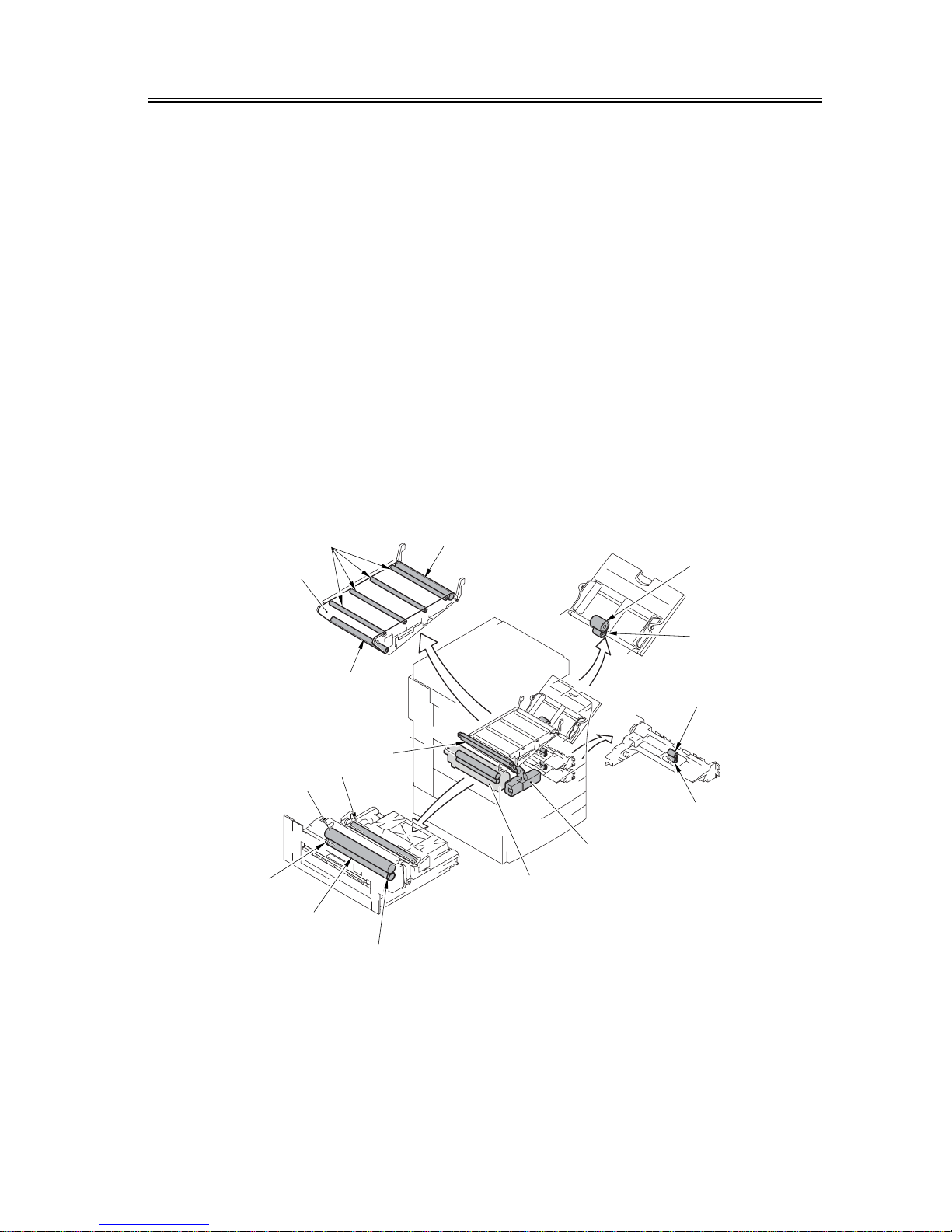
1.2.3 Printer Unit
0006-0005
T-1-1
as of May 2004
Ref. Parts name Parts No. Q'ty Life Remarks
[1] Waste toner container FG6-8992 1 60,000 prints*
[2] Secondary transfer outside
roller (120/230-V)
FG6-8997 1 300,000 prints* actual number of
prints
[3] Transfer cleaning unit FG6-8989 1 100,000 prints*
[4] Fixing roller FB6-3641 1 100,000 prints* actual number of
prints
[5] Pressure roller FB6-3653 1 100,000 prints* actual number of
prints
[6] Transfer belt FB6-2930 1 300,000 prints* actual number of
prints
[7] Drive roller FB6-2931 1 300,000 prints* actual number of
prints
[8] Primary toner roller RB2-6870 4 300,000 prints*
[9] Secondary transfer inside
roller
FB6-2934 1 300,000 prints* actual number of
prints
[10] Feed roller (each cassette
holder)
FB6-3406 2 250,000 prints* actual number of
prints
Chapter 1
1-3
F-1-1
[11] Separation roller (each
cassette holder)
FB6-3406 2 250,000 prints* actual number of
prints
[12] Feed roller (manual feeder) FB1-8581 1 120,000 prints* actual number of
prints
[13] Separation roller (manual
feeder)
FB5-0873 1 120,000 prints* actual number of
prints
[14] Fixing upper fram e unit FG6-9645 1 100,000 prints*
[15] Fixing unit (100 V) FG6-9070 1 200,000 prints*
[15] Fixing unit (120 V) FG6-9069 1 200,000 prints*
[15] Fixing unit (230 V) FG6-9070 1 200,000 prints*
[16] Pressure roller bearing XG9-0478 2 100,000 prints* actual number of
prints
*: Assumes the use of A4 originals with a 5% image ratio.
as of May 2004
Ref. Parts name Parts No. Q'ty Life Remarks
[6]
[7][8]
[9]
[10]
[11]
[12]
[13]
[4]
[16]
[5]
[2]
[1]
[15]
[3]
[16]

Chapter 1
1-4
1.3 Scheduled Servicing Basic Procedure
1.3.1 Scheduled Servicing (Reader Unit)
0006-0013
Do not use solvents or oils that are not indicated herein.
T-1-2
Points to Note About Scheduled Servicing
Unless otherwise specifically mentioned, use lint-free paper and alcohol for cleaning.
- If you used solvent for cleaning, be sure that th e solv ent has completely dried before mounting the part back to the
machine.
- Unless specifically mentioned, do not use a wet (moist) cloth for cleaning.
- See to it that scheduled servicing and replacement are conducted as indicated.
Unit name Location Cleaning Remarks
Optical assembly Scanner cable inspect if dirt is appreciable
Optical path Scanner rail lubricate if dirt is appreciable
Copyboard glass clean if dirt is appreciable
No. 1 through No. 3
mirrors
clean if dirt is appreciable
Original reflecting plate clean if dirt is appreciable
Original size sensor clean if dirt is appreciable
Lens clean if dirt is appreciable
Chapter 1
1-5
F-1-2
Scanning lamp
Dry wipe with lint-free paper.
Lens
Use a blower brush.
Clean the face/back and white plate.
Scanner rail
Lubricate.
Scanner cable
Inspect.
Copyboard glass
Delivery upper
guide
Delivery lower
guide
Fixing inlet guide
Dry wipe with
lint-free paper.
Face-down
delivery roller 1
Intermediate
transfer belt
Face-down
delivery roller 2
External delivery
roller
Internal delivery
roller
Duplex feed roller
Duplex
feed
roller
Secondary
transfer rear
guide
Duplex
feed
roller
Registration
lower roller
Registration
upper roller
Duplex feed
roller
Pickup vertical
path roller
Pre-registration
roller
Reversing roller
Reversing roller
No. 1 through No. 3 mirror
Use a blower brush; if dirt
cannot be removed, dry wipe
with lint-free paper.
Tension roller
(when replacing
the ITB)
Drive roller
(when replacing
the ITB)
Secondary
transfer
internal
roller
(when replacing
the ITB)
Reflecting plate
Clean with a blower brush.
Original size sensor
Use a blower brush.
Note: Unless otherwise indicated and for guides coming into
contact with paper, use lint-free paper and alcohol.
(ITB; when
replacing it)

Chapter 1
1-6
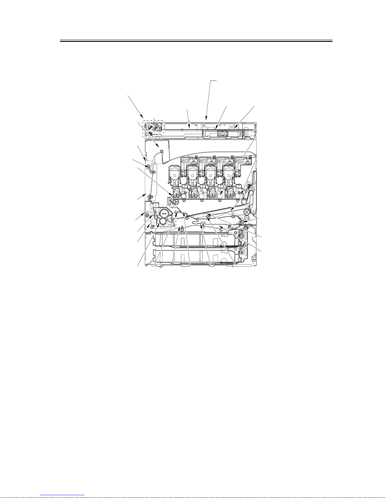
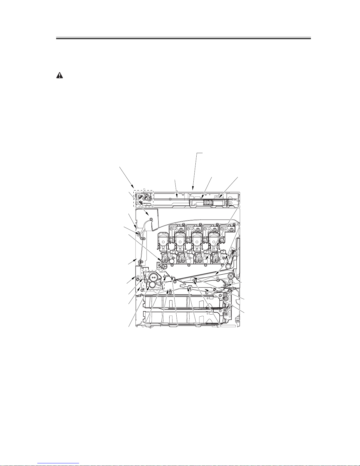
1.3.2 Scheduled Servicing (Printer Unit)
0006-0015
Do not use solvents or oils that are not indicated herein.
T-1-3
Maintenance intervals
Unit name Location every 40,000 150,000 Other Remarks
Delivery unit Internal delivery roller clean if dirt is appreciable
External delivery roller clean if dirt is appreciable
Duplex feed unit Duplex roller 1 clean if dirt is appreciable
Duplex roller 2 clean if dirt is appreciable
Duplex roller 3 clean if dirt is appreciable
Duplex roller 4 clean if dirt is appreciable
Delivery vertical
path unit
Reversing roller clean
Face-down delivery roller 1 clean
Face-down delivery roller 2 clean
Fixing unit Fixing inlet guide clean if dirt is appreciable
Fixing inlet roll clean if dirt is appreciable
Delivery upper guide clean if dirt is appreciable
Delivery lower guide clean if dirt is appreciable
Manual feed
registration unit
Pre-registration roller clean if dirt is appreciable
Registration upper roller clean if dirt is appreciable
Registration lower roller clean if dirt is appreciable
Pickup vertical path roller clean if dirt is appreciable
Intermediate
transfer unit
Drive roller clean or, when replacing th e
intermediate transfer belt
Tension roller clean or, when replacing the
intermediate transfer belt
Secondary transfer internal
roller
clean or, when replacing the
intermediate transfer belt
Internal transfer belt (inside) clean or, when replacing the
intermediate transfer belt
Secondary
transfer unit
Secondary transfer rear guide clean if dirt is appreciable
Chapter 1
1-7
Points to Note About Scheduled Servicing
Unless otherwise specifically mentioned, use lint-free paper and alcohol for cleaning.
- If you used solvent for cleaning, be sure that th e solv ent has compl etely drie d before mo unting the part back to the
machine.
- Unless specifically mentioned, do not use a wet (moist) cloth for cleaning.
- See to it that scheduled servicing and replacemen t a re con ducted as indicated.
F-1-3
Scanning lamp
Dry wipe with lint-free paper.
Lens
Use a blower brush.
Clean the face/back and white plate.
Scanner rail
Lubricate.
Scanner cable
Inspect.
Copyboard glass
Delivery upper
guide
Delivery lower
guide
Fixing inlet guide
Dry wipe with
lint-free paper.
Face-down
delivery roller 1
Intermediate
transfer belt
Face-down
delivery roller 2
External delivery
roller
Internal delivery
roller
Duplex feed roller
Duplex
feed
roller
Secondary
transfer rear
guide
Duplex
feed
roller
Registration
lower roller
Registration
upper roller
Duplex feed
roller
Pickup vertical
path roller
Pre-registration
roller
Reversing roller
Reversing roller
No. 1 through No. 3 mirror
Use a blower brush; if dirt
cannot be removed, dry wipe
with lint-free paper.
Tension roller
(when replacing
the ITB)
Drive roller
(when replacing
the ITB)
Secondary
transfer
internal
roller
(when replacing
the ITB)
Reflecting plate
Clean with a blower brush.
Original size sensor
Use a blower brush.
Note: Unless otherwise indicated and for guides coming into
contact with paper, use lint-free paper and alcohol.
(ITB; when
replacing it)

Chapter 1
1-8

Chapter 2 Standards and
Adjustments


Contents
Contents
2.1 Image Adjustments ............................................................................................................................................2-1
2.1.1 Standards for Image Position .....................................................................................................................2-1
2.1.2 Checking the Image Position ......................................................................................................................2-1
2.1.3 Adjusting the Left/Right Margin (Cassette) ...............................................................................................2-2
2.1.4 Adjusting the Left/Right Margin (Manual Feed Tray) ...............................................................................2-3
2.1.5 Adjusting the Left/Right Margin (Side Paper Deck) ..................................................................................2-3
2.1.6 Duplex Unit ................................................................................................................................................2-4
2.2 Scanning System ...............................................................................................................................................2-5
2.2.1 After Replacing the Scanning Lamp ..........................................................................................................2-5
2.2.2 After Replacing the Copyboard Glass ........................................................................................................2-5
2.2.3 After Replacing the CCD Unit ................................................................................................................... 2-5
2.3 Laser Exposure System .....................................................................................................................................2-6
2.3.1 After Replacing the Laser Unit .................................. ................................................................................2-6
2.4 Image Formation System ...................................................................................................................................2-7
2.4.1 After Replacing the Drum Unit ..................................................................................................................2-7
2.4.2 After Replacing the Transfer Unit ................................. .............................................................................2-7
2.4.3 After Replacing the Pattern Reading Unit ..................................................................................................2-7
2.5 Fixing System ....................................................................................................................................................2-8
2.5.1 After Disassembling the Fixing Unit ..........................................................................................................2-8
2.6 Electrical Components ...................................................................................................................................... 2-9
2.6.1 When Replacing the Reader Controller PCB .............................................................................................2-9
2.6.2 When Replacing the DC Controller PCB ...................................................................................................2-9
2.6.3 When Replacing the Main Controller PCB (main) ..................................................................................2-10
2.6.4 When Replacing the Main Controller PCB (sub) .....................................................................................2-10
2.6.5 When Replacing the SRAM PCB ............................................................................................................2-10
2.6.6 When Replacing the HDD ........................................................................................................................2-11
2.6.7 When Replacing the Power Supply PCB .................................................................................................2-11
2.7 Pickup/Feeding System ...................................................................................................................................2-12
2.7.1 Adjusting the Horizontal Registration When Replacing the Pickup Cassette ..........................................2-12
2.7.2 Adjusting the Horizontal Registration When Replacing the Duplex Unit ...............................................2-13

Chapter 2
2-1
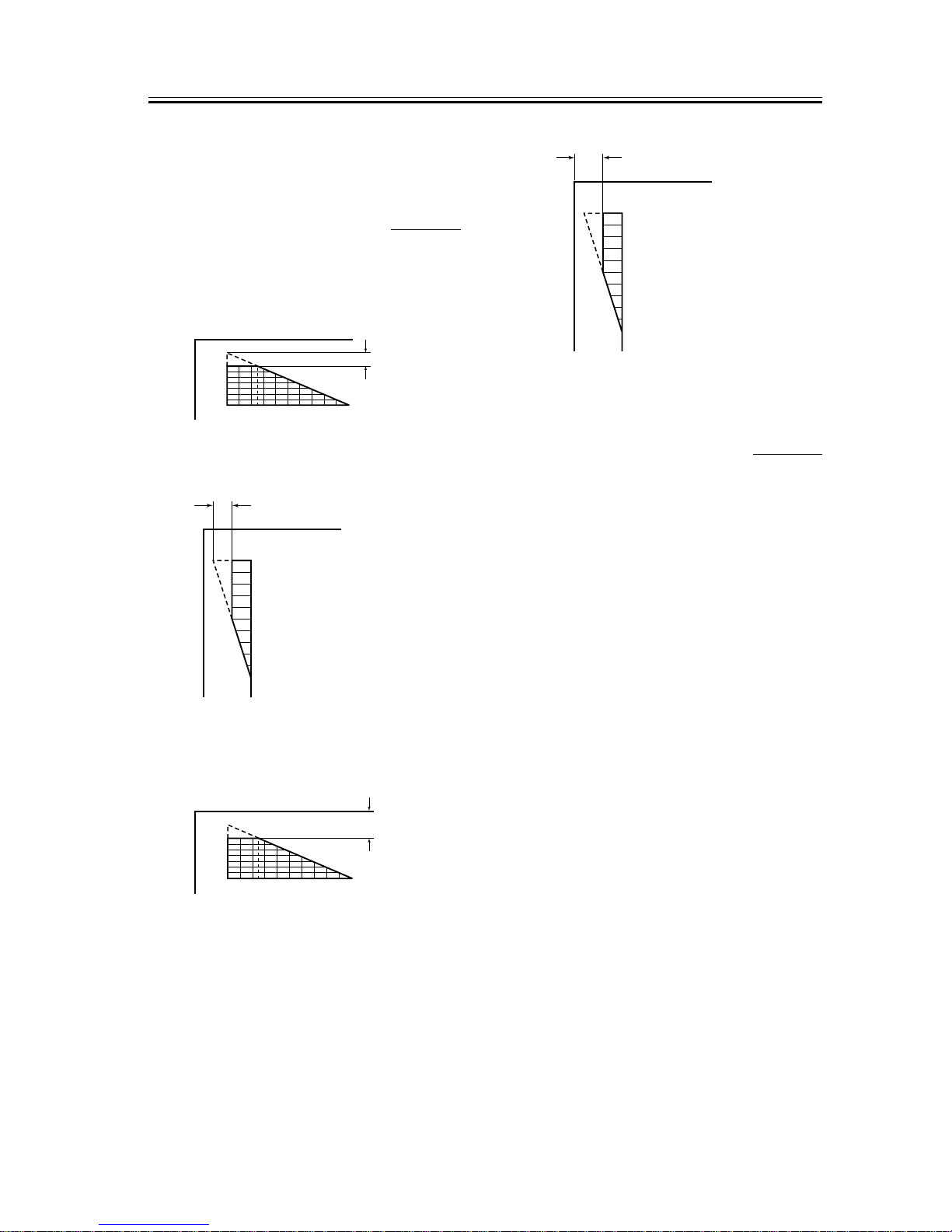
2.1 Image Adjustments
2.1.1 Standards for Image
Position
0000-5345
The standards for the image margin/non-image width
of prints made at 100% are as follows:
F-2-1
F-2-2
F-2-3
F-2-4
2.1.2 Checking the Image
Position
0000-5346
Make 10 prints each using the following as the source
of paper, and check to see that the image margin and
non-image width are as indicated:
[1] individual cassettes
[2] manual feed tray
[3] side paper deck
[4] duplex unit
If not, perform the following:
1) left/right image margin adjustment (horizontal
registration adjustment)
2) leading edge image margin adjustment (registration
adjustment)
3) left-right non-image width adjustment (CCD read
start cell position adjustment)
4) leading edge non-image width adjustment (scanner
image leading edge position adjustment)
Adjusting the Image Leading Edge Margin
1) Make the following selections in service mode, and
see that the image margin is as indicated:
COPIER>ADJUST>FEED-ADJ>REGIST.
254 6 8 1012141618200
(2nd side of double-sided
copy: 2.5±2.0mm)
2.5±1.5mm
10
8
6
5
4
2
0
2.0±1.5mm
(2nd side of double-sided copy:
2.0±1.5mm)
254681012141618200
2.5±1.5mm
(2nd side of double-sided
copy:2.5±2.0mm)
10
8
6
5
4
2
0
2.0±1.5mm
(2nd side of double-side copy:
2.0±1.5mm)
Chapter 2
2-2
F-2-5
Adjusting the Left/Right Non-Image Width
1) Make the following selections in service mode, and
see that the non-image width is as indicated:
COPIER>ADJUST>ADJ-XY>ADJ-Y.
F-2-6
Adjusting the Leading Edge Non-Image Width
1) Make the following selections in service mode, and
see that the non-image width is as indicated:
COPIER>ADJUST>ADJ-XY>ADJ-X.
F-2-7
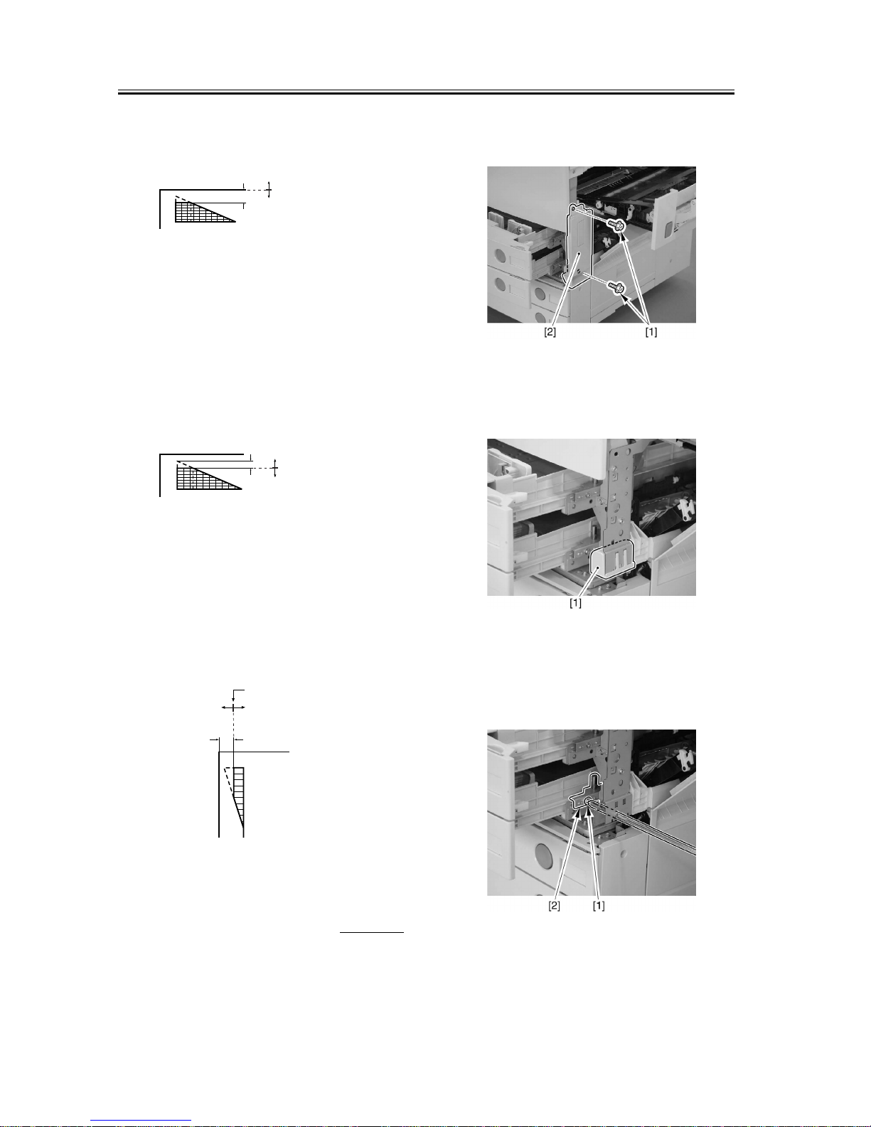
2.1.3 Adjusting the Left/
Right Margin (Cassette)
0000-5347
1) Slide out the cassette 1/2, and open the pickup
vertical path cover.
2) Remove the 2 screws [1], and detach the right front
cover [2].
F-2-8
3) Detach the grip [1] found at the right front. (If
only the cassette 2.)
F-2-9
4) Insert a screwdriver through the hole in the right
front stay, and loosen the screw [1] to adjust the
position of the adjusting plate [2].
F-2-10
Leading edge of paper
Decease the
value of REGIST.
(A decrease of ‘10’
will increase
the margin by 1 mm.)
Increase the
value of REGIST.
(An increase of ‘10’
will decrease
the margin by 1 mm.)
254681012141618200
2.5±1.5mm
(2nd side of duplex
copy: 2.5±2.0mm)
Image leading edge
Decrease the
value of ADJ-X.
(A decrease of ‘10’
will decrease
the non-image
width by 1 mm.)
Increase the
value of ADJ-X.
(An increase of ‘10’
will increase
the non-image
width by 1 mm.)
254681012141618200
2.5±1.5mm
(2nd side of
double-sided
copy: 2.5±2.0mm)
Edge of image
Increase the value of ADJ-Y.
(An increase of ‘10’ will increase
the non-image width by 1 mm.)
Decrease the
value of ADJ-Y.
(A decrease of ‘10’
will decrease
the non-image
width by 1 mm.)
10
8
6
5
4
2
0
2.0±1.5mm
(2nd side of double-sided
copy: 2.5±1.5mm)
Chapter 2
2-3
F-2-11
- For output from each cassette, check to make
sure that the margin (L1) along the leading edge
is 2.5±1.5 mm; if not, make the following
adjustments:
1) Make the following selections in service mode:
COPIER>ADJUST>FEED-ADJ>REGIST.
2) Change the setting to make adjustments.
(A change of '1' will cause a shift of 0.1 mm, and a
higher value will move the image toward the
leading edge.)
F-2-12
- Adjusting the Image Area (non-image width)
1) Make the following selections in service mode:
COPIER>ADJUST>BLANK>BLANK-T/L/B/R.
2) Change the setting to make adjustments.
(An increase by '24'incr ea ses the non-image width by
about 1mm, with the range of settings being between
0 and 100.)
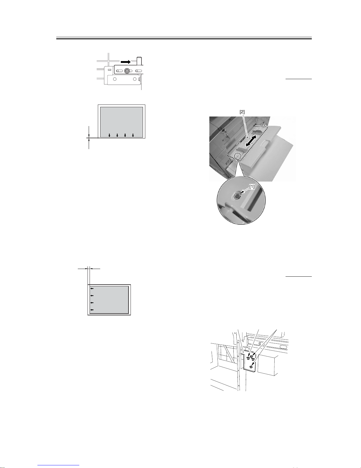
2.1.4 Adjusting the Left/
Right Margin (Manual
Feed Tray)
0000-5348
Loosen the 2 screws [1], and move the position of the
slide guide [2] to make adjustments.
F-2-13
2.1.5 Adjusting the Left/
Right Margin (Side Paper
Deck)
0000-5349
1) Slide out the compartment, and adjust the position
of the latch plate [1] of the compartment opening
solenoid (SL102) using the 2 screws. (When doing
so, refer to the index [3] on the latch plate.)
F-2-14
Image
L2
Decrease the margin at
the front of the paper.
Moving the adjusting
plate to the right
Image
L1
Increasing the value of FEED-ADJ will move
the image toward the leading edge of the paper.
(left rear of compartment)
[1]
[3]
[2]
Chapter 2
2-4
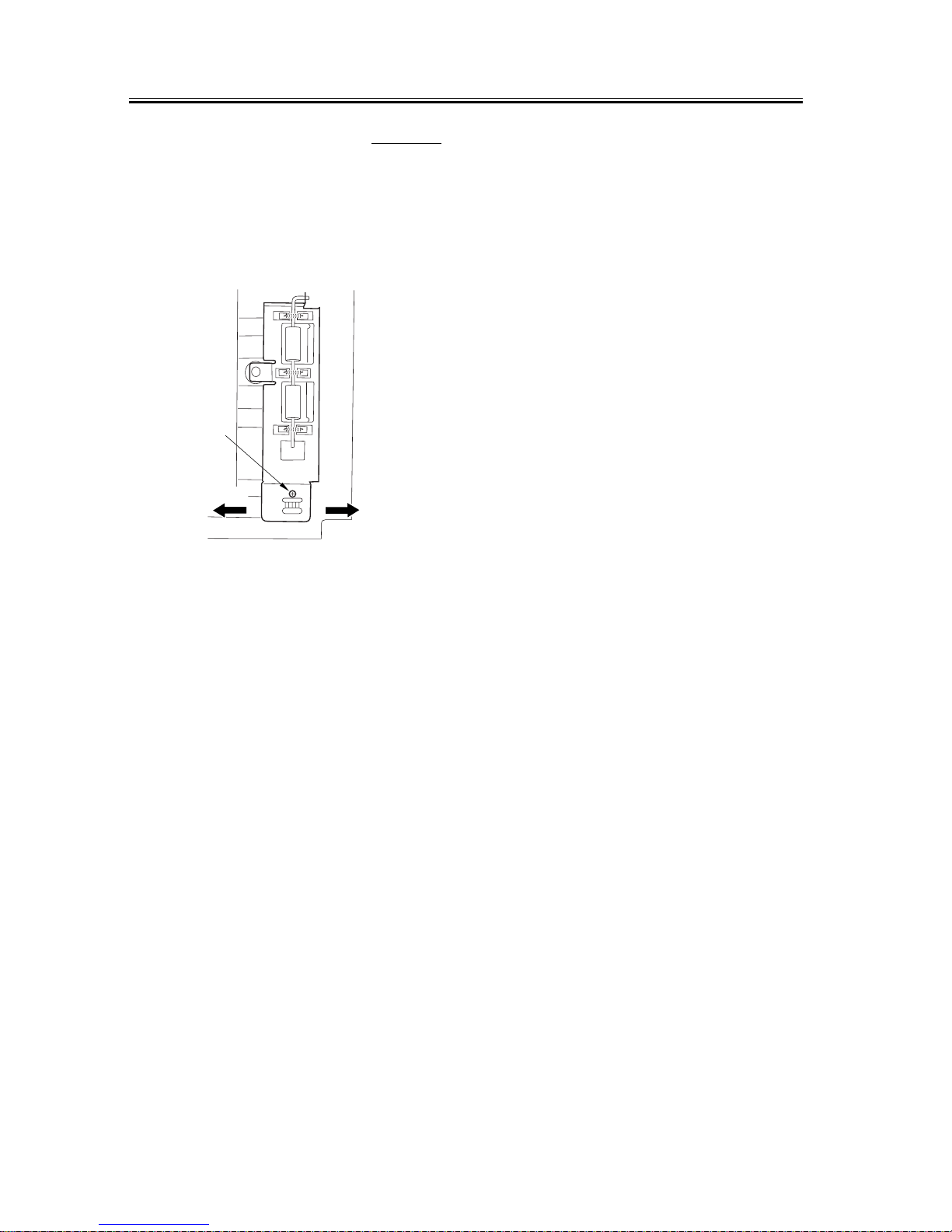
2.1.6 Duplex Unit
0000-5350
Loosen the adjusting screw [1] to make adjustments.
(A single graduation in the inde x will cause a chang e
of approximately 1 mm.)
- To move the paper to the rear, move it to the left.
- To move the paper to the front, move it to the right.
F-2-15
[1]
left
right
 Loading...