

Page 1
PUB. MIE-0014-000
Video Display
• Before use, be sure to read this guide, including the safety and handling precautions.
• Reading this guide will help you learn to use the video display properly.
• Store this guide safely so that you can use it in the future.
Instruction Manual
English
Page 2

Table of Content
2
Introduction 3
About this manual 3
Trademarks 3
Supplied Accessories 3
Important Usage Instructions 4
Safety Instructions and Handling
Precautions 5
Features 10
Nomenclature 11
Installation/Connection 13
Carrying the video display 13
Removing the carrying handle 13
Attaching the protective plate: PP-17U Protect
Panel (sold separately) 14
Removing/attaching the stand 15
Preventing from Tipping 16
Mounting the Main Unit on a Stand or Wall 17
Mounting the Main Unit on a 19 Inch
Rack: RB-02 Rack Mount Bracket (sold
separately) 18
Connecting the Main Unit to Input Devices 20
Changing the screen display area (for video of
4096x2160) 28
Performing calibrations 28
Export/Import 30
Set Date/Time 32
Inputting Characters 32
Using the Function (F) Buttons 33
Using the Channel (CH) Button 33
Checking Signal Information and Status of the
Main Unit 34
Operating the video display using an external
device
Operating the video display using an external
device
REMOTE terminal(GPI)
LAN terminal
35
34
OSD Menu 36
OSD Menu Index 36
Adjustment 40
Channel Settings 53
Display Settings 56
Audio Settings 59
Marker Settings 60
Function Settings 65
System Settings 72
Signal Information 78
System Information 78
Turning on the Power 22
Turning on the Power of the Main Unit 22
Attaching/detaching the HC-01 AC Power Cord
Clamp (provided) 23
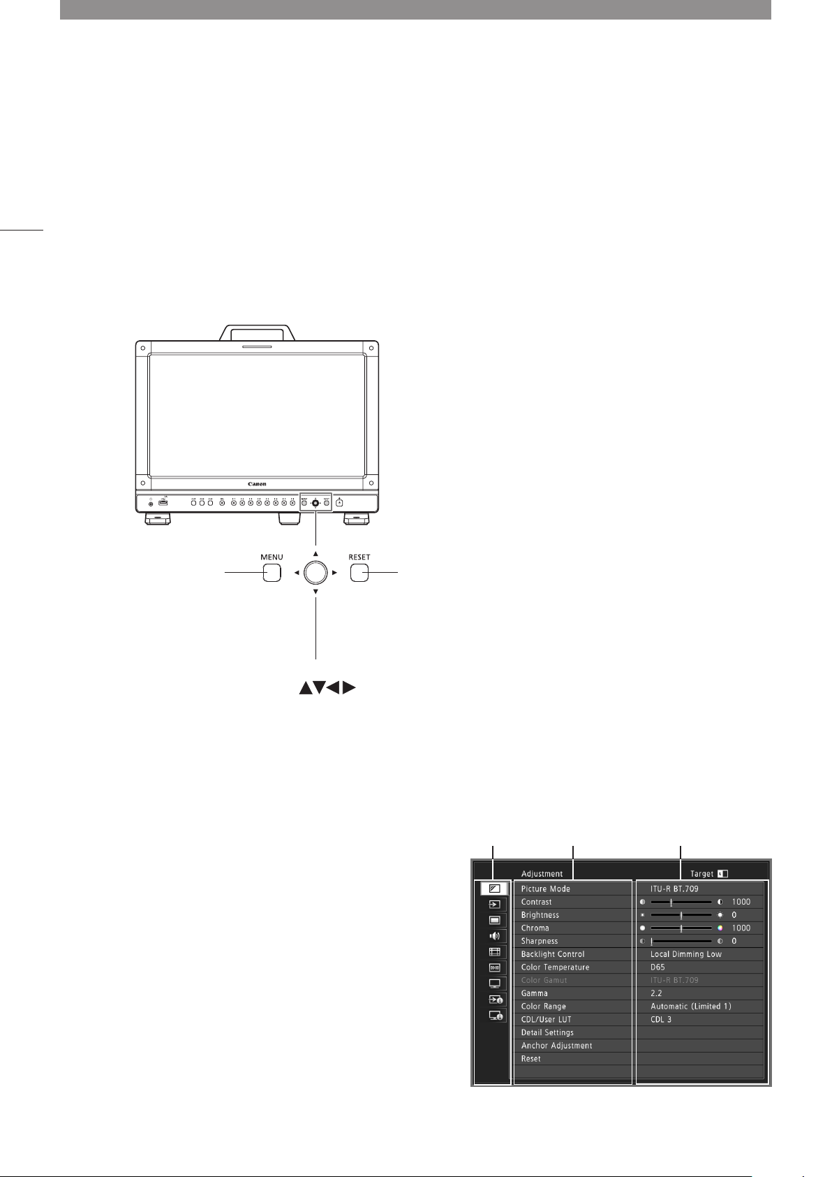
Operating the Video Display 24
Basic operations to use the OSD menu 24
Adjusting Image Quality While Viewing the Entire
Image 25
Temporarily Saving Parameters (Anchor Point
Setting) 27
Enlarging the display (Zoom function) 27
Adjusting image quality for each screen in two
screen display 28
Main specifications/Performance 79
Dimensions 81
Appendix 82
Supported Signal Format 82
Image/Frame Display 96
Error Messages 99
Troubleshooting 102
Software Used in This Product 104
Index 106
Page 3
Introduction
Thank you for purchasing the Video Display DP-V1710.
The On Screen Display (thereafter referred to OSD) default language setting is English. To change the OSD menu
language setting, please refer to p. 72.
About this manual
Some of the illustration used in the manual have been simplified for clarity.
Conventions used in this manual
: Indicates a reference page.
Note: Indicates a note.
Reference: Indicates reference information.
CAUTION: Indicates an item you must observe.
Trademarks
• HDMI, HDMI logo, and High-Definition Multimedia Interface are trademarks or registered trademarks of HDMI
Licensing LLC in the U.S. and other countries.
• VESA is a registered trademark or trademark of Video Electronics Standards Association in the U.S. and other
countries.
• Other product and company names herein are trademarks or registered trademarks of their respective owners.
3
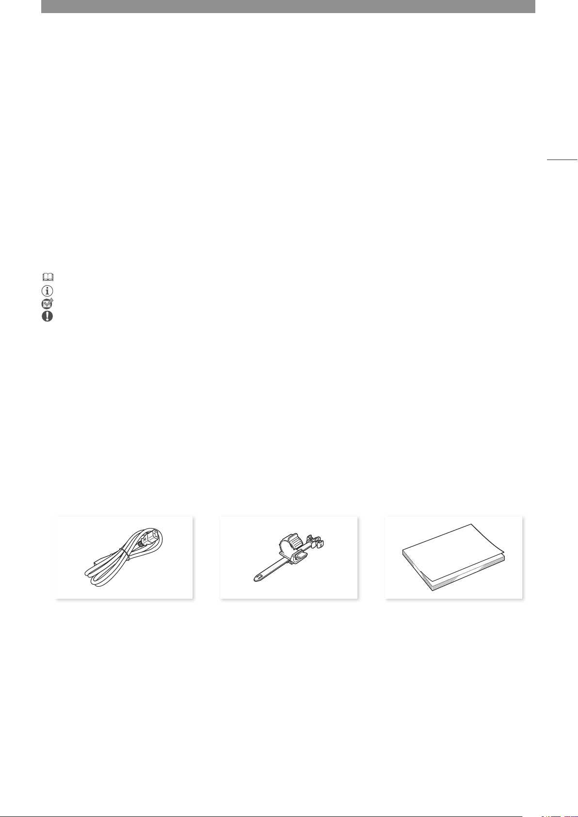
Supplied Accessories
The following items are supplied with this product. Please check before using.
AC Power Cord HT-21 AC Power Cord clamp
HC-01
DP-V1710 Instruction Manual
(this document)
Page 4
Important Usage Instructions
For the customers in the U.S.A.
4
This equipment has been tested and found to comply with the limits for a Class A digital device, pursuant to Part 15 of
the FCC Rules.
These limits are designed to provide reasonable protection against harmful interference when the equipment is
operated in a commercial environment. This equipment generates, uses, and can radiate radio frequency energy
and, if not installed and used in accordance with the instruction manual, may cause harmful interference to radio
communications. Operation of this equipment in a residential area is likely to cause harmful interference in which case
the user will be required to correct the interference at his own expense.
Do not make any changes or modifications to the equipment unless otherwise specified in the manual. If such changes
or modifications should be made, you could be required to stop operation of the equipment.
Use of shielded cable is required to comply with class A limits in Subpart B of Part 15 of FCC Rules.
This device complies with Part 15 of the FCC Rules. Operation is subject to the following two conditions: (1) This device
may not cause harmful interference, and (2) this device must accept any interference received, including interference
that may cause undesired operation.
Canon U.S.A Inc.
One Canon Park, Melville, NY 11747, U.S.A.
Tel No. (631)330-5000
For the customers in Canada
CAN ICES-3 (A) / NMB-3 (A)
For the customers in Europe
Warning;
This is a class A product. In a domestic environment this product may cause radio interference in which case the user
may be required to take adequate measures.
CANON INC.
30-2, Shimomaruko 3-chome, Ohta-ku, Tokyo 146-8501, Japan
CANON EUROPA N.V.
Bovenkerkerweg 59, 1185 XB Amstelveen, The Netherlands
Only for European Union and EEA (Norway, Iceland and Liechtenstein)
This symbol indicates that this product is not to be disposed of with your household waste,
according to the WEEE Directive (2012/19/EU) and national legislation. This product should
be handed over to a designated collection point, e.g., on an authorized one-for-one basis
when you buy a new similar product or to an authorized collection site for recycling waste
electrical and electronic equipment (EEE). Improper handling of this type of waste could have
a possible negative impact on the environment and human health due to potentially hazardous
substances that are generally associated with EEE. At the same time, your cooperation in the
correct disposal of this product will contribute to the effective usage of natural resources. For
more information about where you can drop off your waste equipment for recycling, please
contact your local city office, waste authority, approved WEEE scheme or your household waste
disposal service. For more information regarding return and recycling of WEEE products, please
visit
www.canon-europe.com/weee.
Page 5

Safety Instructions and Handling Precautions
Be sure to read these instructions in order to operate the product safely.
Follow these instructions to prevent injury or harm to the operator of the product or others.
WARNING
Denotes the risk of serious injury or death.
•Do not disassemble or modify the video display.
Inside, the video display contains high-voltage/extremely hot/movable parts that can cause fire, electric shock, burns or
injury.
•Do not insert foreign objects or liquids into the video display.
If metallic objects, flammable objects or liquids get inside the video display, this may cause fire, electric shock or
malfunction.
•Be sure to use the correct voltage.
Using a power source with a voltage other than that specified in this instruction manual can cause fire or electric shock.
Always use the supplied (or specified) AC power cord. For your safety, do not use this AC power cord to power other
equipment.
•Do not connect non-standard input voltage to the DC input terminal.
Applying non-standard input voltage to the DC input terminal can cause a fire or electric shock.
•Do not use the video display in the following places.
Doing so can cause fire, electric shock or malfunction.
-Close to a window when it is raining or snowing.
-Places subject to high humidity and dust.
-Places exposed to water and moisture such as bathrooms, kitchens etc.
-Places directly exposed to dust, smoke or steam, or nearby heaters and humidifiers.
-Places where flammable gases may be present.
-Places exposed to direct sunlight.
•Do not install or store the video display in places exposed to direct sunlight.
The video display's internal temperature can rise and cause fire or malfunction.
•Do not damage the power cord.
Do not place heavy objects on the power cord and do not pull, modify, heat or tie the power cord in a bundle. The power
cord may be damaged (exposed or broken wires, etc.) and cause fire or electric shock.
•When using three-pronged plugs with a ground connection:
Always connect the ground prong.
A short circuit occurring when the ground prong is not connected can cause fire or electric shock.
The video display's power cable features a three-pronged plug.
•Do not touch the power cable or plug during lightning storms.
This can cause electric shock.
•Do not touch the power cable or plug with wet hands.
This can cause electric shock.
5
Page 6

Safety Instructions and Handling Precautions
•Observe the following precautions regarding the power source and power plug.
Failing to do so can cause fire or electric shock.
-Insert the power plug fully and securely into the power outlet. Do not use a damaged power cable or plug or a
loose power outlet.
6
-Hold the plug itself when unplugging the power cable. Pulling the power cord can damage the power cord and
cause fire or electric shock.
-Periodically remove any dust buildup from the power plug.
-Do not obstruct the access to the power plug by placing other objects around it.
-Do not connect many power cords to the same power outlet.
-When using an extension cable, make sure the total power consumption of the devices you connect to the
extension cable does not exceed its rated power.
•If the video display was dropped or exposed to a strong impact, turn it off immediately and unplug the power
plug.
The video display is a precision instrument and continued use in such case can result in a short circuit and cause fire or
electric shock.
•Before starting any maintenance work, turn off the video display and unplug the power plug.
Failing to do so can cause electric shock.
•In any case of unusual circumstances such as the presence of smoke or abnormal sounds or smell,
immediately turn off the video display and unplug the power plug.
Continued use can cause fire or electric shock.
•Before moving, installing, removing or connecting the video display to peripheral devices, turn off the video
display and all connected devices and unplug their power plugs.
Failing to do so can cause fire, electric shock or malfunction.
•For your safety, unplug the power plug from the power outlet when not using the video display for extended
periods of time.
Dust buildup on the power plug can cause fire.
•Do not obstruct the access to the power plug so it can always be easily unplugged.
Failing to disconnect the power plug immediately after unusual circumstances have occurred can cause fire or electric
shock.
•Do not block the ventilation holes.
Blocking the video display's vent holes can result in the internal temperature rising and cause fire or malfunction. Observe
the following precautions to ensure proper ventilation.
-Do not push the video display into narrow confined spaces or enclosures.
-Do not wrap the video display in cloth or other materials.
-Do not place the video display facing up, lay it sideways or upside-down.
•If the screen is damaged, do not touch the leaking liquid crystal or other internal liquids.
If the LCD panel is damaged and liquid crystal or other internal liquids leak out, do not put the liquids in the mouth, inhale
or swallow it or let it come in contact with the skin. If the liquids get in the eye or mouth, wash it immediately with plenty
of water. If the liquids come in contact with the skin or clothes, wipe them immediately with alcohol etc. and wash the
exposed area with soap. Leaving the liquids untreated can cause injury or damage.
•Use the carrying handle to carry the video display.
When carrying the video display, be sure to hold it by the carrying handle. Failure to do so could cause the display to fall
and cause an injury.
•Keep all packaging material out of the reach of children.
Packaging material tightly wrapped around someone's head can result in strangulation or suffocation.
Page 7

CAUTION
Denotes the risk of injury.
Safety Instructions and Handling Precautions
•Do not place any objects on the video display and do not climb on it.
The video display can tip or fall and cause injury.
•Do not install the video display on an unstable surface.
Installing the video display on a wobbly or slanted surface can cause the display to tip or fall and cause injury. Thoroughly
check also the strength and sturdiness of the surface where the video display will be placed or installed.
•Take precautions to prevent the video display from tipping or falling.
In an earthquake the video display can tip or fall. For your safety, when installing the video display on a TV stand or other
furniture, take precautionary measures to secure the video display against tipping or falling ( 16). Taking such measures
can be effective in reducing the risk of injury or damage but the effectiveness of the prevention measures cannot be
guaranteed in all earthquakes.
•Always follow the specified procedure to install the video display ( 13).
If the installation is not performed correctly, the video display may tilt or fall and cause injury.
•Inspect the condition of the installation about once per year.
An inadequate fitting or mounting can cause the video display to fall and cause injury.
•Regularly check to ensure that the carrying handle remains securely attached.
If the carrying handle screws are loose or broken, the display could fall and cause an injury.
•Attach the carrying handle securely.
The carrying handle screws should be tightened securely, if they have ever been removed. Failure to do so could cause
the display to fall and cause an injury.
•When using headphones, set the volume at a safe level.
Listening through headphones at a high volume can harm your hearing.
7
Page 8

Safety Instructions and Handling Precautions
When Using the Main Unit
• The screen may be damaged if it is left facing strong source of light. Please take precautions when placing it near a
window.
• Do not press firmly on the screen, scratch it or place an object on the screen. It can cause non-uniformity or damage
8
to the panel.
• The screen and cabinet may become warm during use. Note this does not constitute a malfunction.
About Backlight
The backlight has a limited service life so its brightness may degrade and color may change due to aging.
About Temporary Screen burn-in
If a stationary image is displayed for a prolonged period, screen burn-in may occur where you see remnants of what
was displayed. This is a characteristic of LCD and is not a failure. However, this is only temporary and will disappear
when playing video.
About the LCD screen
The screen is produced using extremely high-precision manufacturing techniques, with more than 99.99% of the pixels
operating to specification. Less than 0.01% of the pixels may occasionally misfire or appear as black, red, blue or
green dots. In addition, this tendency may increase through long term use due to characteristic of the LCD panel.
These do not constitute a malfunction.
Condensation
If this equipment is brought into a warm room while it is cold or if the room is heated suddenly, condensation may form
on the surface or inside the equipment. Note that the equipment may be damaged if it is used under such condition.
If condensation has formed on the surface or inside the equipment, do not use the video display as it may get
damaged. Turn the power off and wait until the condensation has evaporated before using the video display.
Cleaning
• Before cleaning, be sure to unplug the power plug.
• The screen has a special surface treatment, avoid touching it directly with your hand. In addition, never affix
adhesive objects such as seals.
• Never use alcohol or benzene, thinner, acidic cleaning solution, alkaline cleaning solution, abrasive or chemical
wipes because these will damage the screen.
• If the screen is dirty, wipe gently with soft dry cloth such as cleaning cloth or eye glasses cleaning cloth. Wiping the
screen too hard may cause unevenness on the screen or damage the LCD panel. The screen may be scratched if
wiped too hard with a cleaning cloth with foreign particles attached.
• When the screen is extremely dirty, wipe with soft cloth such as cleaning cloth or eye glasses cleaning cloth
moistened with water-diluted neutral detergent.
• Use a blower to remove dust from the surface of the screen.
• Wipe dirt on cabinet with a soft cloth. If the screen is very dirty, use a moistened cloth with water or mild detergent
diluted with water. Do not use alcohol, benzene, paint thinner, or pesticides as they may damage the surface finish
or erase characters on the cabinet.
Page 9

Safety Instructions and Handling Precautions
Disposing
• Do not dispose together with normal waste. Do not include the video display in waste that will be taken to landfill.
• Observe the rules and regulations of your local authorities when disposing.
9
Page 10

Features
The DP-V1710 Video Display provides a wide range of support for video production as a way to check video on
10
location, in a secondary control room in a studio, or in a live broadcast vehicle.
17-Inch 4K display
• Supports UHD broadcast standard (3840x2160)
• Allows for high adjustment precision and high contrast.
• Works with 19-inch rack mount (7U) (complies with EIA standards)
• High uniformity is provided by minimizing the variation due to temperature changes and aging.
• Supports a range of color gamut standards (ITU-R BT.2020, ITU-R BT.709, etc.)
• Equipped with the HDR display function. (SMPTE ST 2084 and Hybrid Log-Gamma are supported)
Includes a range of interfaces to improve ease of use.
• Supports 6G-SDI.
• Supports DC 12 V input (4 XLR pins).
• Includes the REMOTE terminal (GPI) and LAN terminal to allow control from an external device.
• Grading controllers and calibration sensors can be connected from outside using USB ports.
(Tangent Wave's Element-Tk, Konica Minolta’s CA-310, etc.)
Supports a wide range of workflows on location from videoing to editing.
• Supports 4K RAW. A 4K RAW workflow is constructed on ACES2065-1.
• CINEMA EOS SYSTEM link (Supports “Canon Log”, “Canon Log 2”, and “Canon Log 3”. Equipped with functions
to display the camera shooting information and automatically switch adjustment, and to stop the fan in conjunction
with the camera REC signal using meta information from the camera.)
• ARRI Camera System link (Supports the ARRI Cinema Camera Look. Equipped with functions to display the
camera shooting information and automatically switch adjustment, and to automatically switch the area marker
size using meta information from the camera.)
• Supports multiple LUT/CDL settings.
• Supports the “2 Sample Interleave” signal transmission method.
• Supports dual screen and quad screen displays. HDR and SDR content can be displayed for comparison and
image quality adjustment using the dual-screen display.
• Includes built-in Wave Form Monitor, Vector Scope, Zoom, Peaking, False Color, and more.
• Includes a tally light.
Rigidity and flexible installation
• High durability achieved by a metal outer covering
• Includes a convenient carrying handle for portability and a stand designed to ensure stability and prevent tipping.
Page 11
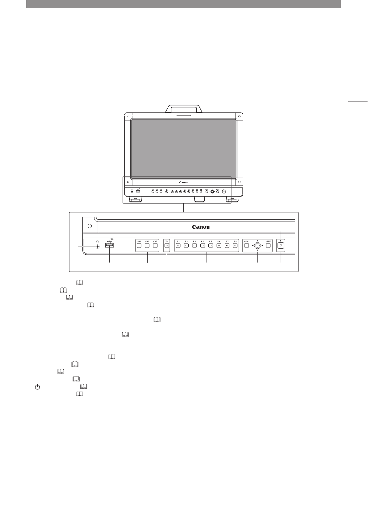
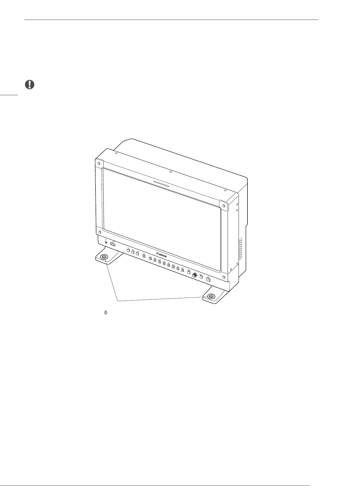
Nomenclature
Front face of the main unit
2
3
4
5
1
6
7
11
3
Aa
8 9 Aq
Carrying handle ( 13)
1
Tally light ( 34)
2
Front stand ( 15)
3
Headphone terminal ( 59)
4
USB port
5
For connecting an external sensor for calibration (
Tangent Wave Ltd).
Channel (CH) button CH1 to CH3 ( 33)
6
CDL button
7
For switching CDL mode.
Function (F) button F1 to F8 ( 33)
8
MENU button ( 24)
9
Jog dial ( 24)
RESET button ( 24)
(Power) button ( 22)
Aq
Power indicator ( 22)
Aa
28), USB memory, hub, or color grading controller (Element-Tk made by
Page 12
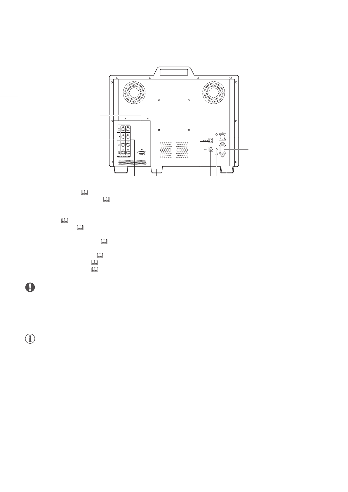
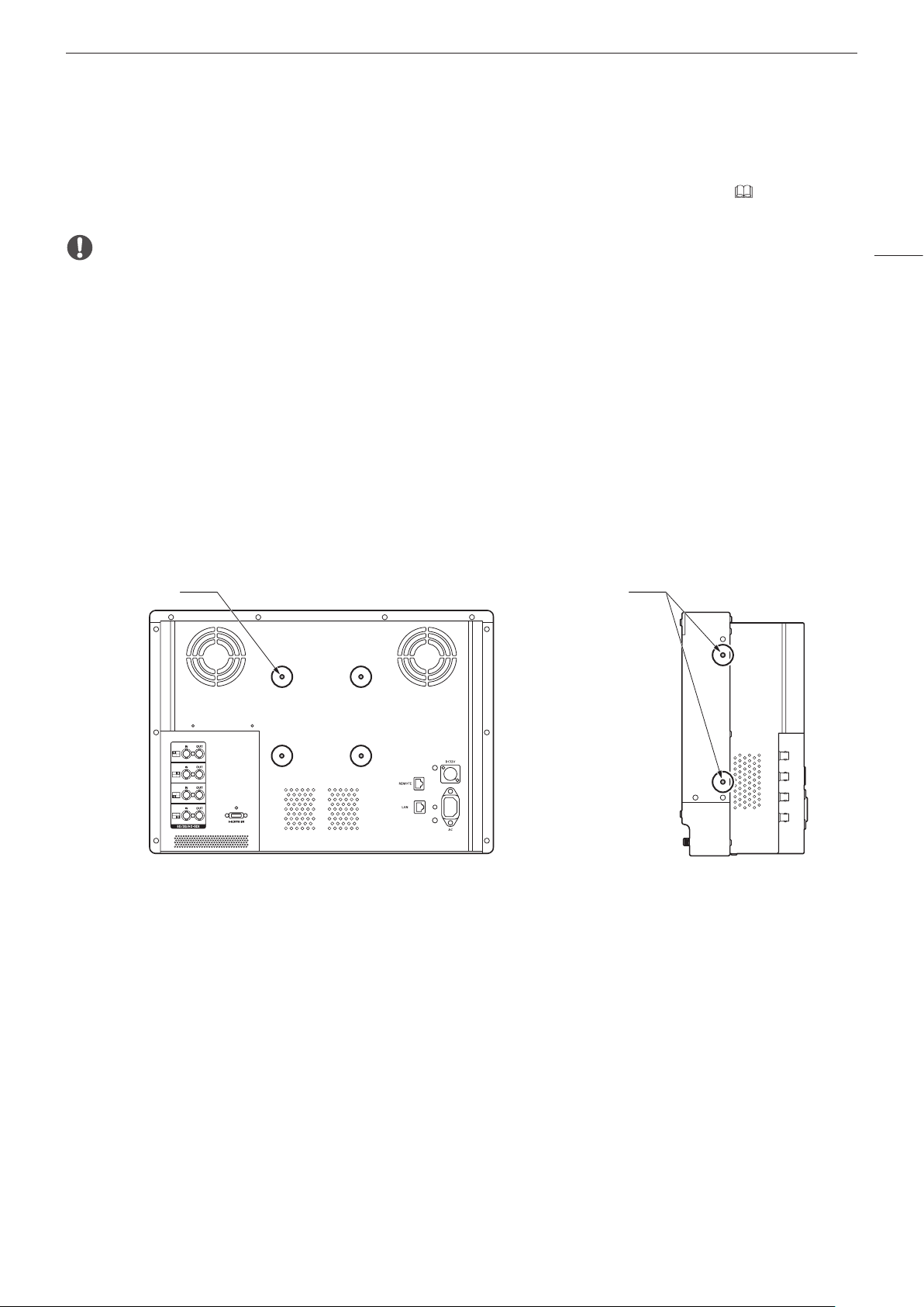
Nomenclature
Al
Sq
Back face of the main unit
12
As
Ad
Af Ag Ah AjAk
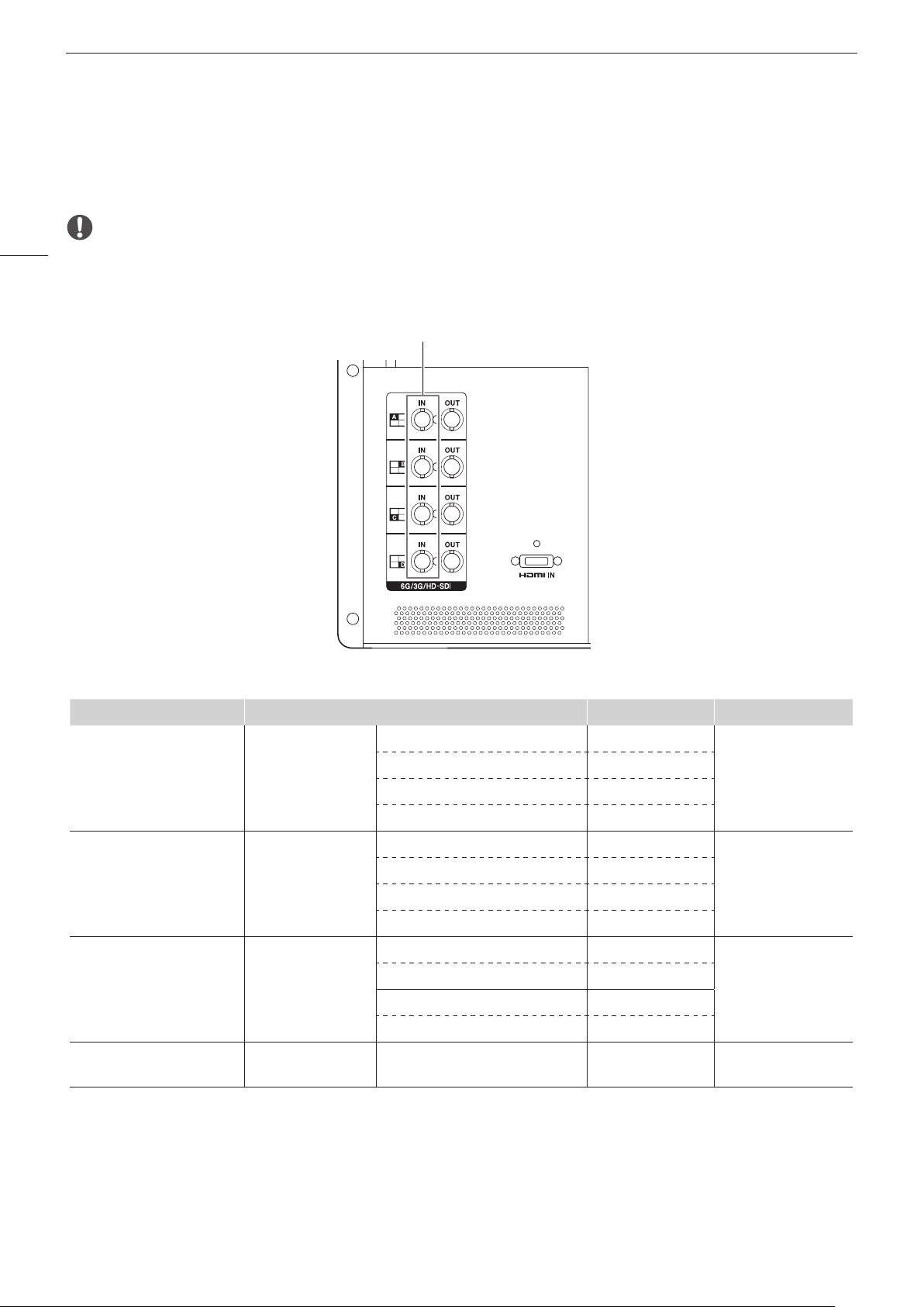
HDMI input terminal ( 21)
As
6G/3G/HD-SDI input terminal ( 20)
Ad
6G/3G/HD-SDI output terminal
Af
For passing through output corresponding to Ad.
Rear stand ( 15)
⑮
REMOTE terminal ( 34)
Ah
For connecting remote control devices.
LAN (10/100 BASE) terminal ( 35)
Aj
For connecting a Display Controller CL-01 (provided with the DP-V3010) and external control device.
Cord clamp mounting hole ( 23)
Ak
AC power input terminal ( 22)
Al
DC power input terminal ( 22)
Sq
Ag
CAUTION
• When connecting an external sensor for calibration to the USB port, the USB cable length must not exceed 3 m (9.8 ft.).
Otherwise, communication error may occur and correct calibration may not be possible.
• For safety, do not connect any connector that may have excessive voltage to the terminal of the video display when connecting
peripheral devices.
Note
• About USB Memory
-Both FAT16 and FAT32 USB memory devices are supported.
-Proper operation cannot be guaranteed for all USB memories.
-It may take 10 seconds or more for the USB memory to be recognized. If the function to save data on a USB memory is
executed during recognition, the message [Detecting USB memory] is displayed.
• When using a Display Controller CL-01 (provided with the DP-V3010) with the main unit, update the controller firmware version to
4.19.0 or later.
Page 13
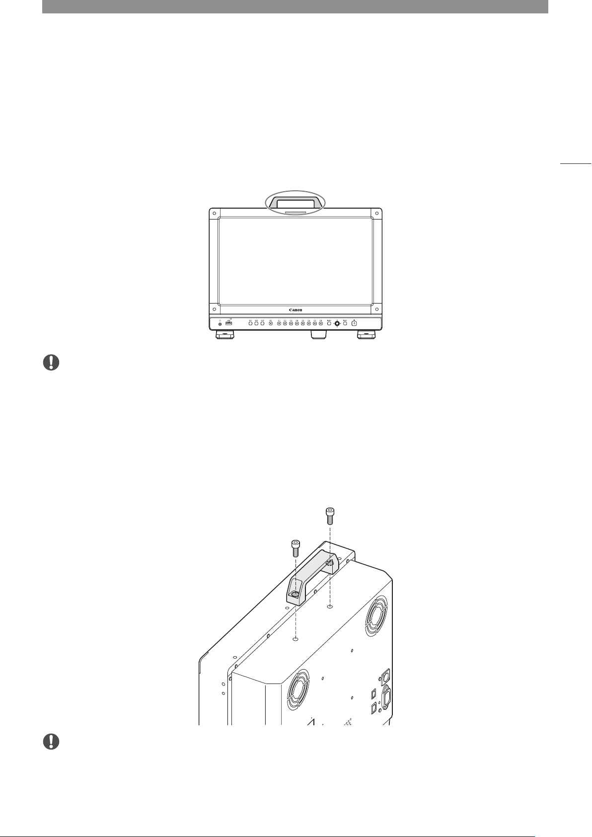
Installation/Connection
Carrying the video display
When carrying the video display, be sure to hold it by the carrying handle.
CAUTION
• When carrying the video display, handle it carefully not to touch or damage the screen.
Removing the carrying handle
13
The carrying handle can be removed.
1 Remove the two screws from the carrying handle, as shown in the diagram below.
•Use a hexagonal key (6 mm).
•Do not lose the screws or carrying handle you removed. Do not use these for other purposes.
CAUTION
• Ensure that you do not touch or damage the screen during this process.
• When attaching a carrying handle to the video display, check that it's securely attached after fastening the screws.
Page 14
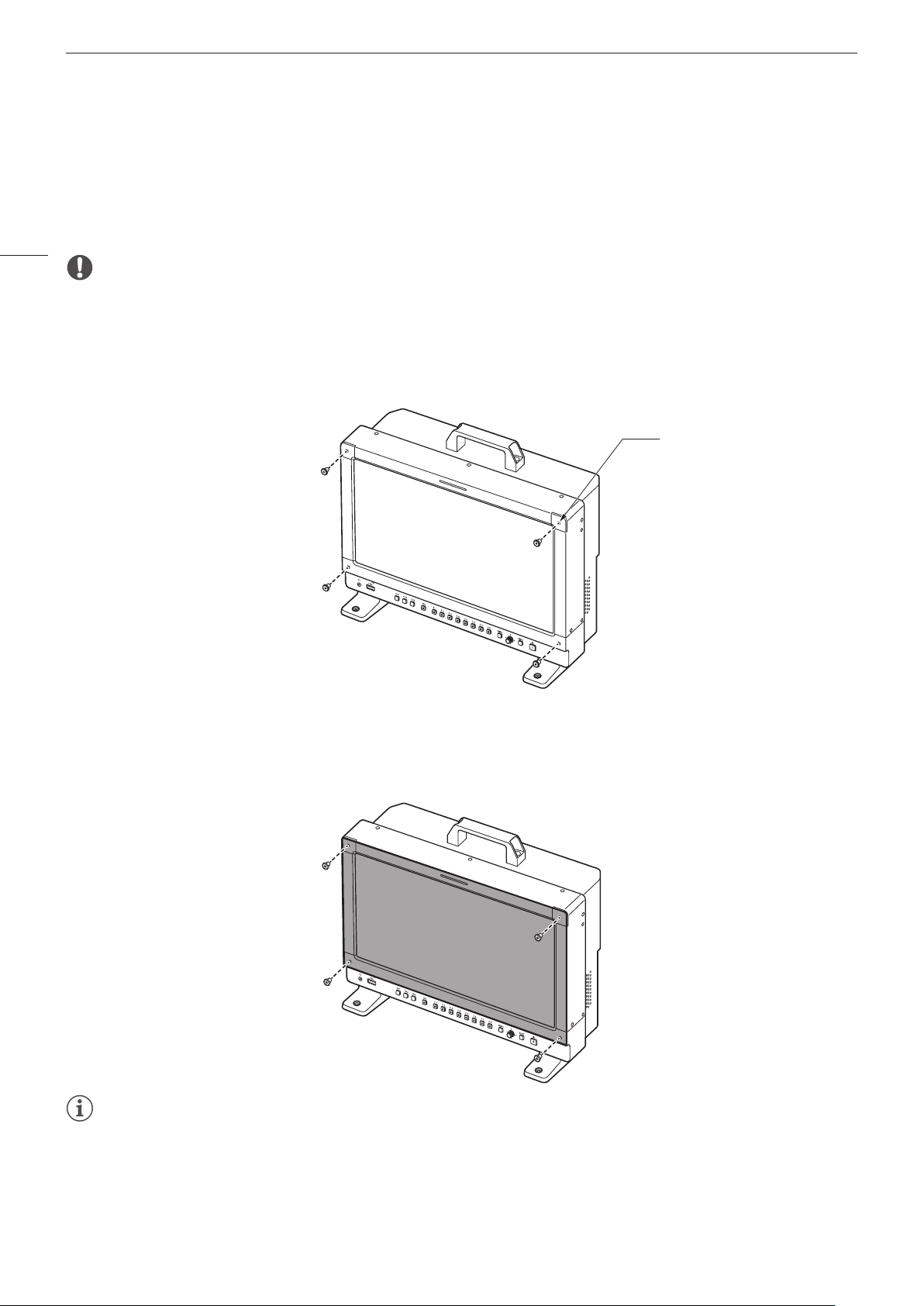
Installation/Connection
Attaching the protective plate: PP-17U Protect Panel (sold separately)
You can attach the protection panel to protect the screen when carrying the video display or when using it outdoors.
The separately-sold PP-17U Protect Panel is attached as follows. Please also see the instruction manual for the
PP-17U Protect Panel.
14
CAUTION
• Avoid touching the screen during this step as it may damage it.
Use the HK-02 Hex Key for the Protect Panel (the 1.5 mm hexagonal key that is supplied with the Protect Panel) to
remove or attach the screws.
1 Unscrew the four screws on the front face of the display.
4-M3
Depth 7 mm (Max.)
2 Remove the protective film from both sides of the Protect Panel.
3 Line up the Protect Panel and the display screw holes and fasten the screws from Step 1.
•Take care when attaching the Protect Panel in order to avoid damaging it.
Note
• When viewing the screen with the Protect Panel in place.
-The colors and brightness may appear different with and without the panel in place.
-Light may reflect off the screen.
Page 15
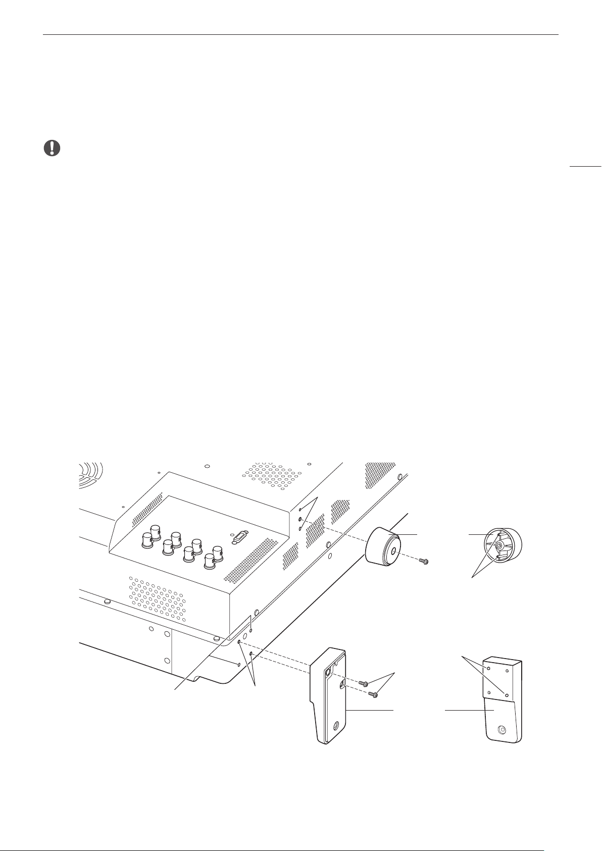
Removing/attaching the stand
The main unit is supplied with two stands which can be detached.
Installation/Connection
CAUTION
• Use a flat, clear surface when attaching/detaching the stands.
• The display can tip over if the stand has not been attached.
• Avoid touching the screen during this step as it may damage it.
Detaching
1 Place the display with the screen facing down on a soft cloth or cushioning material that is larger than the
display.
2 Front stand: Remove the mounting screws (two each) from the left and right stands.
Rear stand: Remove the mounting screws (one each) from the left and right stands.
•Do not lose the removed screws. Do not use these screws for other purposes.
Attaching
1 Place the display with the screen facing down on a soft cloth or cushioning material that is larger than the
display.
2 Align the position of the stand and screw hole on the video display.
•Alight the convex part of the stand and concave part of the video display.
3 Front stand: Fix the left and right stands using the mounting screws (two each).
Rear stand: Fix the left and right stands using the mounting screws (one each).
15
Rear
Screen side
Concave part
Front stand
mounting screw hole
Concave part
Rear stand
Convex part
Convex part
Mounting
screw
Front stand
Page 16
Installation/Connection
Preventing from Tipping
The video display can be fastened down to a desk or table by using the screw holes on the stand.
16
CAUTION
• When securing the main unit to a table or desk, please ensure the table or desk is strong enough to carry the weight of the main
unit.
• It is recommended to obtain assistance from another person when performing this step.
• Avoid touching the screen during this step as it may damage it.
1 Use screws that fit the screw holes to fasten it to a desk or table.
Screw hole
2-
4.5
Page 17
Installation/Connection
Mounting the Main Unit on a Stand or Wall
This main unit can be fitted to a stand* or to a wall mount bracket*. Remove the stands beforehand ( 15).
* Commercially available.
CAUTION
• For safety, make sure to perform this step with at least two people.
• When mounting the main unit on a wall, make sure the wall has sufficient strength. If necessary, apply reinforcement. Also, make
sure to check the load capacity of the stand or wall mount bracket.
• When the video display is placed on a rack or display stand and ventilation around it is blocked by equipment placed above or
below or in a surrounding area, the operating temperature may increase, causing a failure or overheating. In order to maintain the
operating temperature condition of the video display (0 ˚C to 40 ˚C), make space of at least 1U (4.4 cm) above and below and at
least 4 cm (1.6 in.) space from its back. Make sufficient space from peripheral equipment, secure vents, or install a ventilation fan.
• When installing the video display on a wall, make sufficient space from the wall so that cables are not squeezed or twisted.
• Avoid touching the screen during this step as it may damage it.
• Make sure that the main unit does not fall during installation/removal.
1 Attach a commercially available stand or wall mount bracket using the screw holes on the back or side
face of the main unit.
6 mm deep
(Max.)
Rear4×M4
2×M4
7 mm deep
(Max.)
Side
17
Same on the other side
Page 18
Installation/Connection
Mounting the Main Unit on a 19 Inch Rack: RB-02 Rack Mount Bracket
(sold separately)
This video display is compatible with a 19-inch rack mount (7U / complies with EIA standards). The video display
18
can be attached to a 19-inch rack using the separately-sold RB-02 Rack Mount Bracket. The angle can be selected
depending on how it is attached (–15/–6/6/15 degrees). Remove the carrying handle and stand before starting work
( 13, 15).
The Rack Mount Bracket is supplied with the SW-04 and SW-05 screws for attaching it. Please also see the instruction
manual for the RB-02 Rack Mount Bracket.
CAUTION
• For safety, make sure to perform this step with at least two people.
• When the video display is placed on a rack and ventilation around it is blocked by equipment placed above or below or in a
surrounding area, the operating temperature may increase, causing a failure or overheating. In order to maintain the operating
temperature condition of the video display (0 ˚C to 40 ˚C), make space of at least 1U (4.4 cm) above and below and at least 4 cm
space from its back. Make sufficient space from peripheral equipment, secure vents, or install a ventilation fan.
• Ensure that you do not touch or damage the screen during this process.
• Make sure that the main unit does not fall during installation/removal.
1 Attaching a Rack Mount Bracket to the Video Display.
•Use the SW-04 screws in two locations each on the left and right.
Rack Mount Bracket Screw
SW-04
Side view
Same on the other side
Page 19
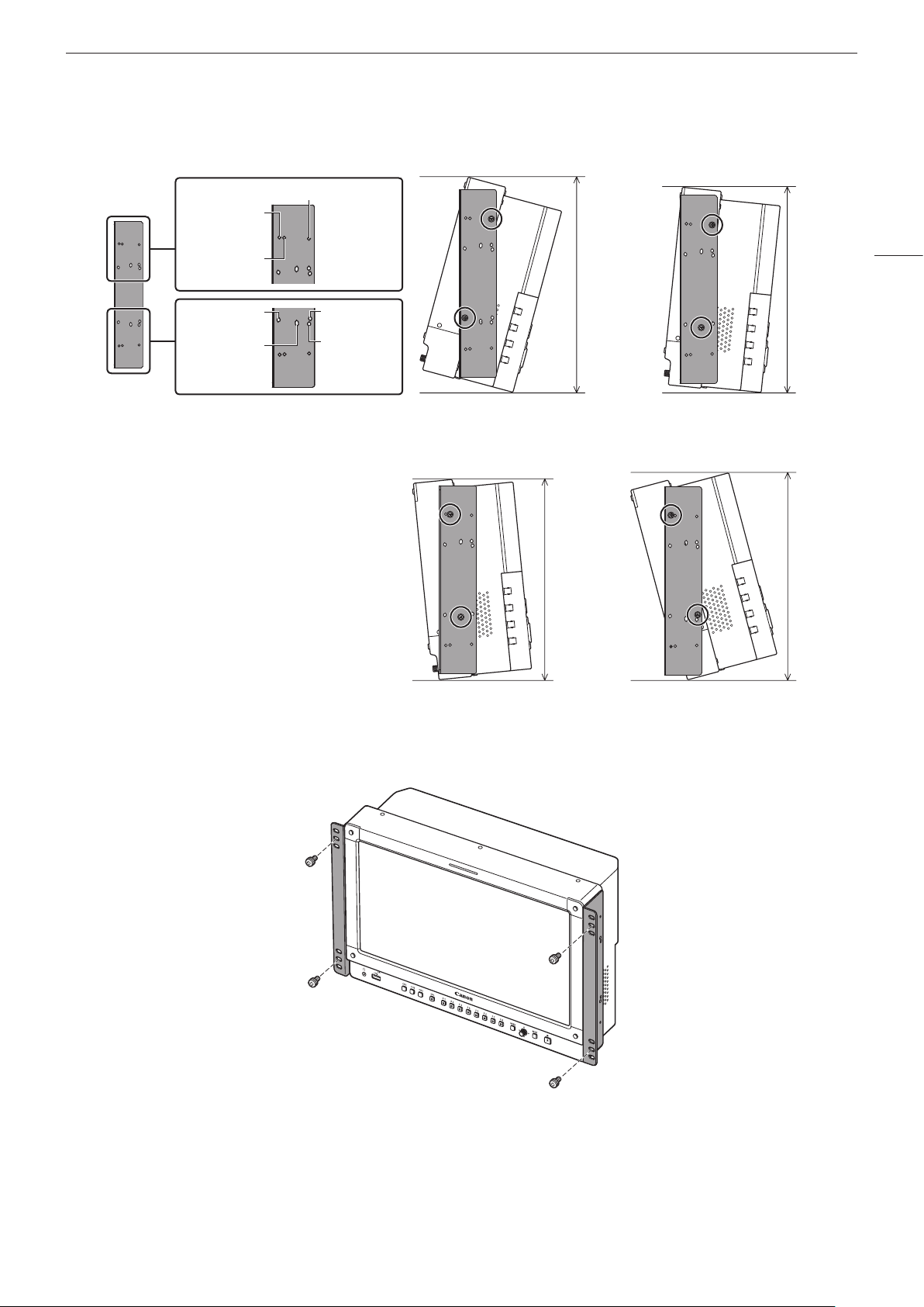
•Screw positions for attaching the display at –15, –6, +6, or +15 degrees
–15/–6/0 degrees
15 degrees
6 degrees
–15 degrees 15 degrees
Approx.
334 mm
Installation/Connection
19
Approx.
320 mm
–6/6 degrees
0 degree
–15 degree angle
6 degree angle
2 Attach the video display to the rack.
•Use the SW-05 screws in two locations each on the left and right.
Approx.
312 mm
–6 degree angle
Approx.
322 mm
15 degree angle
Rack Mount Bracket Screw
SW-05
Page 20
Installation/Connection
Connecting the Main Unit to Input Devices
The video display has 6G/3G/HD-SDI and HDMI input terminals to connect input devices.
20
CAUTION
• Check that the power of the video display and input devices is switched off before connecting.
SDI input signals
SDI (IN) terminal
Input signal Input terminal
Quad Link
(Square Division)
Quad Link
(2 Sample Interleave)
Dual Link
Single Link 6G/3G/HD-SDI
1
The signals are automatically switched when [Image Division] is set to [Automatic].
1
1
3G/HD-SDI Top left, Mapping signal Input A
Top right, Mapping signal Input B
Bottom left, Mapping signal Input C
Bottom right, Mapping signal Input D
3G-SDI Link 1 Input A
Link 2 Input B
Link 3 Input C
Link 4 Input D
6G/3G-SDI Link 1 Input A
Link 2 Input B
Link 1 Input C
Link 2 Input D
—
Input A/Input B/
Input C/Input D
Single input system
Single input system
Two input systems
Four input systems
Page 21
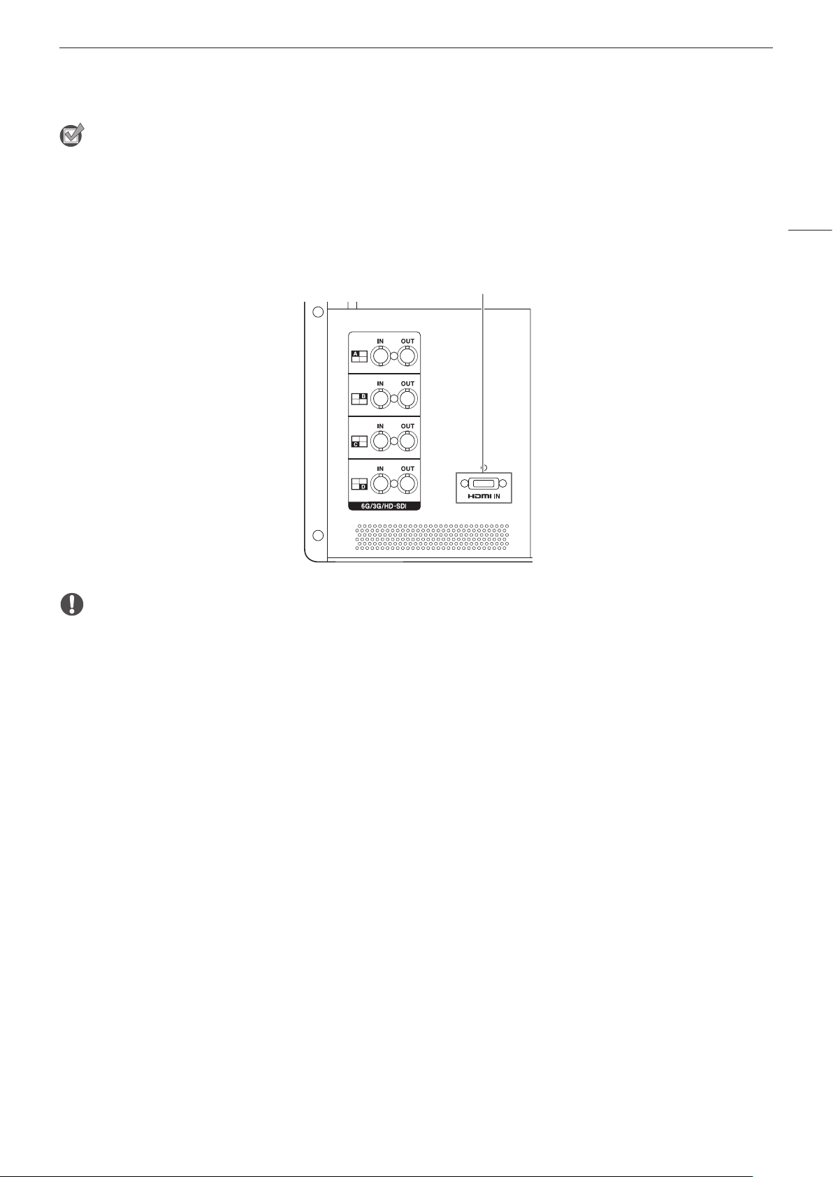
Installation/Connection
Reference
• The connection is tested using Canare Corp. BNC cable (multi) 4VS03A-5C.
• When 3G-SDI RAW signal frequency exceeds 30.00P, it becomes a dual connection.
• Each input terminal is compatible with through output. When signals are input from Input A, connect the cable to the SDI (OUT)
terminal of Input A.
HDMI input signal
HDMI input terminal
21
CAUTION
• Use a HDMI cable with the High Speed logo that complies with the HDMI standard. When a non-compliant HDMI standard cable
is used, the video display may not work normally, for example a video becomes choppy or nothing is displayed.
Page 22
Turning on the Power
22
Turning on the Power of the Main Unit
1 When using AC power supply
Plug the provided AC power cord HT-21 to the AC power supply input terminal at the rear.
•The video display goes into standby and the power indicator lights up in amber.
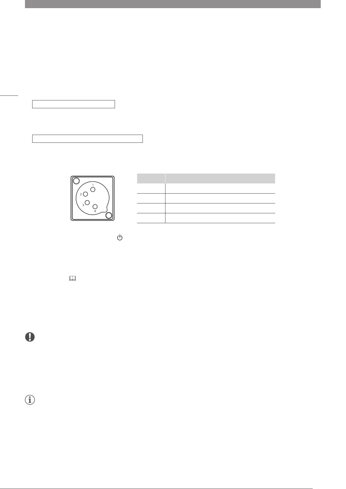
1 When using DC power supply (12 V DC)
Insert the DC power cord into the DC power supply input terminal at the rear.
•When connected normally, the video display goes into standby and the power indicator lights up in amber.
•DC power supply input terminal specifications are shown below.
Pin No. Signal
1 - (GND)
2 N.C.
3 N.C.
4 + (12 V, max. 10 A)
2 Press the power supply button at the front.
•The power indicator lights green.
About the power indicator
Displays the status of the main unit. The brightness of the power indicator can be set from [Off] or [1 (dark)] to
[5 (brightest)] ( 73). The power indicator will flash during firmware updates or when an error is detected even if it is
set to [Off].
Off: when power supply is not connected
Green lit: when a power supply is connected and the power of the video display is on
Green flash: during calibration or firmware update
Amber lit: during standby (a power supply is connected and the power to the video display is off)
Amber flash: when error is detected
CAUTION
• Check the specifications of the DC power supply input terminal and use a power supply that is compatible with the video display.
Using a power supply with incompatible voltage and polarity may cause fire or electric shock.
• Use a DC power cord with an allowable current of at least 10 A and a length of 2 m or less. If a DC power cord longer than 2 m is
used, the video display may not work normally: for example, the video becomes choppy or nothing is displayed.
• Do not connect cables for audio devices or sound cables to the DC power supply input terminal, as it may cause damage to the
display unit.
Note
• Warming-up is necessary to stabilize the brightness of the video display. Wait at least 10 minutes after turning on the power before
using.
• When an AC power supply is connected during the use of DC power supply, the power source is switched to the AC power
supply. When this happens, the power is turned off temporarily and then turned on again.
Page 23
Turning on the Power
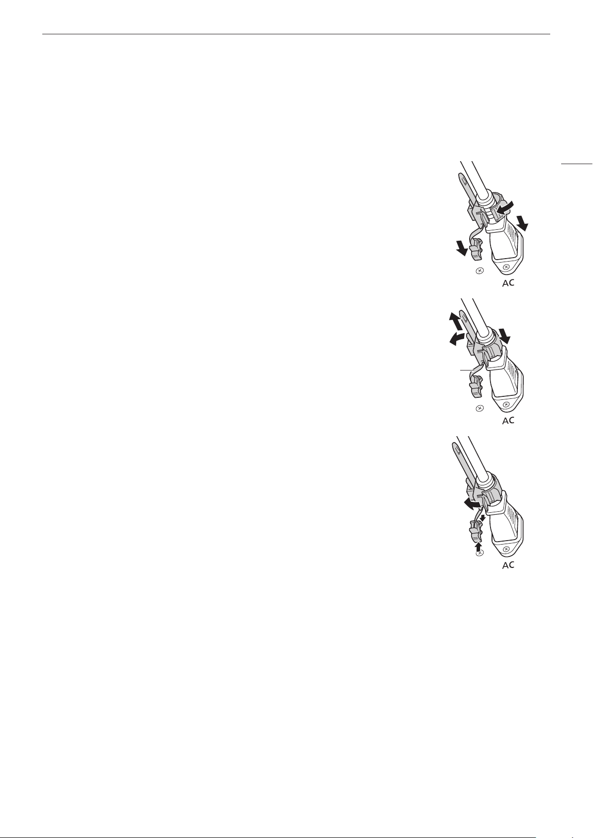
Attaching/detaching the HC-01 AC Power Cord Clamp (provided)
Attaching
Install the AC power cord clamp before connecting the AC power cord to the main unit.
1 Insert the AC power cord clamp connector into the cord clamp mounting hole
(1).
23
2 Connect the AC power cord to the main unit (2).
3 Secure the AC power cord in place with the holder (3).
• The holder should always be fastened in the position shown in the illustration of
the AC power cord.
4 Press the holder against the main unit (4).
• Make sure that there is no slack (A).
Pulling the holder lock lever in the direction of the arrow will allow you to adjust the
•
holder position (5).
Detaching
1 Pull the holder lever in the direction of the arrow (6) and remove the AC
power cord clamp from the AC power cord.
2 Press the knobs on the top and bottom and pull out the AC power cord
clamp from the video display (7).
3
2
1
4
5
A
6
7
Page 24
Operating the Video Display
Using buttons and jog dial on the video display, you can adjust image quality and configure settings for input signals. In
24
addition, you can assign frequently used functions to the CH (Channel) and F (Function) buttons.
Basic operations to use the OSD menu
MENU button
Opens/closes the OSD
menu, or moves up one
level in a menu.
Jog dial
or rotation: Used to move to a different item and change
Press: Confirms settings or moves the selection frame up/down 1 level.
The video display settings are changed from the OSD menu.
RESET button
Resets the items to be adjusted using the slider and
entered characters.
1 Open the OSD menu.
•Press the MENU button.
2 Select the Main Menu.
•Select the Main Menu item using the jog dial and press it to
determine the selection.
3 Select the Sub Menu.
•Select the Sub Menu item using the jog dial and press it to
determine the selection.
settings.
Main Menu
Sub Menu
Setting Options
Page 25
Operating the Video Display
4 Select the setting to change.
•Select the setting to change using the jog dial and press it
to determine the selection. You will be returned to the Sub
Menu item selection screen.
5 Exit menu.
•Pressing the MENU button will return you to the Main Menu
item selection screen. Pressing the MENU button again will
close the menu screen.
Note
• To adjust image quality, warming-up is necessary to stabilize the brightness of the video display. Wait at least 10 minutes after
turning on the power before using.
• The OSD menu and slider will disappear automatically if no operation is performed for approximately 1 minute. The F button will
disappear automatically if no operation is performed for approximately 10 seconds.
• The settings that cannot be set, are grayed out.
• The following functions can be returned to their factory default settings by pressing the RESET button while adjusting the image
quality.
-[Contrast], [Brightness], [Chroma], [Sharpness], [Power], [Saturation], [Offset], [Slope]
When [Picture Mode]
quality will return you to the settings after calibration.
[User 1] to [User 7]: When executing calibration, pressing the RESET button while adjusting the image
25
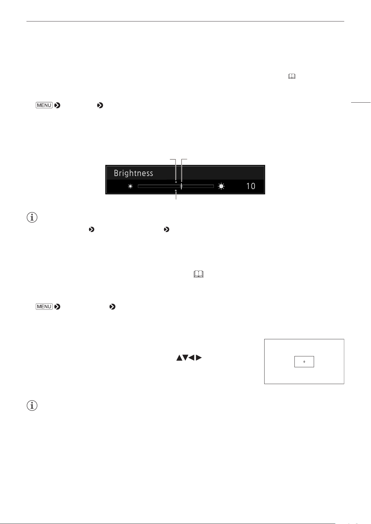
Adjusting Image Quality While Viewing the Entire Image
You can adjust the OSD menu to display as a slider at the bottom of the screen. This allows for the image quality to be
adjusted whilst it is displayed on the screen.
1 Press the jog dial when the selection frame is on setting options.
•A slider appears at the bottom of the screen.
2 Make adjustments using the jog dial with using the slider as
guide.
3 When adjustments are completed, press the jog dial.
•The screen returns to the original OSD menu.
Page 26
Operating the Video Display
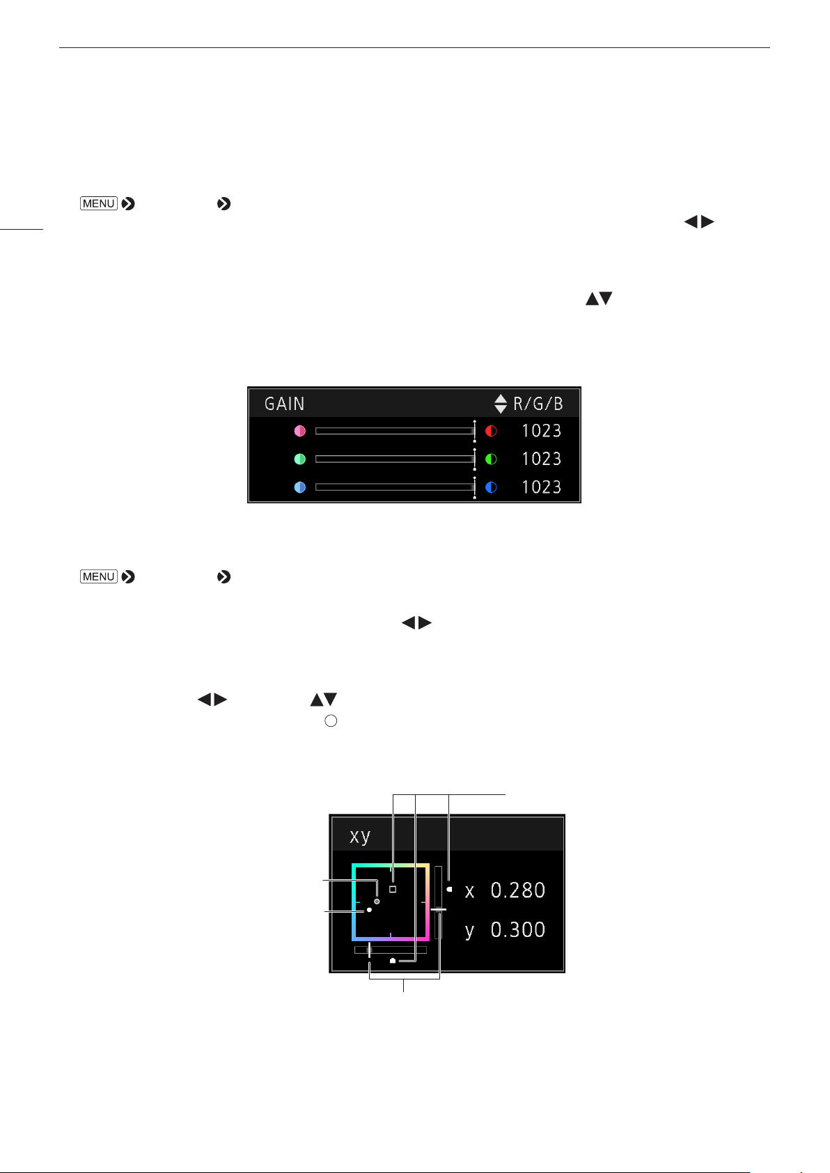
Color temperature detailed settings (gain, bias)
You can adjust RGB all at once or individually when the screens for adjusting [Gain] or [Bias] are displayed.
1 Open the [Color Temperature] menu.
26
2 Select one.
3 Switch the guide in the upper right area of the slider screen using the jog dial ( ).
4 When adjustments are completed, press the jog dial.
[Adjustment] [Color Temperature]
•[Gain R], [Gain G], [Gain B], [Bias R], [Bias G], and [Bias B] can be set individually using the jog dial ( ).
•The setting screen for [Gain] or [Bias] will be displayed.
•The indication changes to [RGB], [R], [G], and [B]. Selecting [RGB] will allow you to adjust RGB as a whole.
•The screen returns to the original OSD menu.
Color temperature detailed settings (xy values)
1 Open the [Color Temperature] menu.
[Adjustment] [Color Temperature]
2 Select [Custom (xy)].
•You can set [x] and [y] individually using the jog dial ( ).
3 Select either [x] or [y].
•The color map is displayed.
4 Adjust [x] with the
•The adjusted value is indicated by the " " mark on the color map.
5 When adjustments are completed, press the jog dial.
•The screen returns to the original OSD menu.
and [y] with .
Last used value
Current value
Default value
Current value
Page 27
Operating the Video Display
Zoom 2 [x4]
Temporarily Saving Parameters (Anchor Point Setting)
You can temporarily save parameters for [Contrast], [Brightness], [Chroma], and [Sharpness]. See 44 for setting
anchor points during CDL adjustment.
1 Open the [Anchor Adjustment] menu.
[Adjustment] [Anchor Adjustment]
2 Press the jog dial, and when the confirmation screen appears, select [OK].
•The parameter is saved and the anchor point is set.
3 Adjust the image quality again and press the RESET button on the video display.
•Returns you to the anchor point for each function.
Current valueLast used value
Anchor point
Note
• Executing [Adjustment] [Reset] or [System Settings] [Reset All Settings] resets saved anchor points and the settings return
to their factory default values.
• When calibration is executed, the values are saved as anchor points.
Enlarging the display (Zoom function) ( 57)
27
The zoom display position can be adjusted, and the zoom magnification (2x, 4x, 8x) can be selected.
1 Open the [Zoom] menu.
[Display Settings] [Zoom]
2 Select [Zoom Preset] using the jog dial.
•Select a preset zoom display.
3 Select [Position] using the jog dial.
•The zoom adjustment screen is displayed.
-To move the display position: Move the jog dial ( or rotation).
-To return to the center: Press the RESET button.
4 When adjustments are completed, press the jog dial.
•The screen returns to the original OSD menu.
Note
• When magnifying the image and the OSD menu is not being displayed, you can set the magnification ratio by pressing the jog
dial.
Page 28
Operating the Video Display
Adjusting image quality for each screen in two screen display ( 53)
In Multi View (Dual) display, image quality settings can be changed
on both displayed screens.
28
1 Open the [Select Input Signal] menu.
[Channel Settings] [Select Input Signal]
•Select [Dual Input A,B] or [Dual Input C,D], and then press the jog
dial to confirm the setting.
2 Open the [Image Division] menu.
[Channel Settings] [Image Division]
•Select [Multi View (Dual)], and then press the jog dial to confirm the setting. The screen changes to two screen
display.
•When selecting [Adjustment] menu, the currently selected screen is identified by L or R (Left or Right) being
displayed on the OSD menu screen.
3 Select a different [Picture Mode] for the left and right screens.
•Select [Picture Mode] in the screen on the left: [Channel Settings] [Picture Mode]
•Select [Picture Mode] in the screen on the right: [Channel Settings] [Picture Mode R]
4 Adjusting the image quality.
5 When adjustments are completed, press the jog dial.
•The screen returns to the original OSD menu.
Switching the target screen
•When the OSD menu is open:
-In the [Adjustment] main menu, press the jog dial’s button.
-In the [Adjustment] main or sub menu, press the CH1 button.
•When the OSD menu is not being displayed: Move the jog dial (
).
Note
• In the [Multi View (Dual)] display, the HDR (High Dynamic Range) and SDR (Standard Dynamic Range) displays can be tested side
by side. ([Adjustment]
[Detail Settings] [HDR/SDR View] 46)
Changing the screen display area (for video of 4096x2160)
When a video signal of 4096x2160 is input, the left and right parts will be trimmed for display.
1 Press the jog dial ( ) while the OSD menu is closed.
•Shifts to the left or right.
Performing calibrations ( 46)
You can perform calibration using an external sensor, without using a computer.
The supported external sensors are Konika Minolta Display Color Analyzers CA-310 and CA-210. Be sure to also read
the instruction manual of the CA-310 and CA-210.
1 Connect the display color analyzer to the USB port of the main unit.
Page 29
Operating the Video Display
2 Select [User 1] to [User 7] and then open the [Calibration] menu.
[Adjustment] [Picture Mode] [User 1] to [User 7]
1
[Adjustment] [Detail Settings] [Calibration]
2
•Set each target value.
3 Press the jog dial and select [Start].
•Please follow the information indicated on the screen.
4 Initialize the sensor.
•Set the mode dial of the Universal Measuring Probe to [0-CAL].
•Press the jog dial of the video display, select [OK], and execute initialization.
5 Place the universal measuring probe pointing at the center of the video display.
•Set the mode dial of the universal measuring probe to [MEAS] and place the probe as shown below according to
the displayed content. Press the jog dial of the video display, select [OK], and execute calibration.
Main Unit
29
Konica Minolta Universal Measuring Probe
CA-310 support: CA-PU32, CA-PU35
CA-210 support: CA-PU12, CA-PU15
Konica Minolta
Display Color Analyzer CA-310, CA-210
6 Finish calibration.
•When the message [Calibration is completed]. is displayed, press the jog dial and select [OK].
•If the message [Calibration error.] is displayed.
Calibration has been terminated due to an error. The main unit returns to the state before calibration. (
99)
•To cancel calibration
Press the jog dial during calibration and select [Cancel]. The main unit returns to the state before calibration.
Note
• Perform matrix calibration of the display color analyzer prior to calibration. If calibration is performed without performing matrix
calibration, an error may occur. Refer to the CA-310 and CA-210 instruction manual for the detail operation.
• Warming-up is necessary to stabilize the brightness of the video display. Wait at least 10 minutes after turning on the power before
calibration.
• Perform calibration in a dark room so that no external light enters the sensor. If external light enters the sensor, low brightness
characteristics cannot be calibrated correctly.
• Due to the characteristic of LCD panel and individual difference of CA-310 and CA-210, the calibration results may differ.
Page 30
Operating the Video Display
Export/Import
You can export/import LUT and CDL parameters as well as main menu settings.
LUT Import ( 45)
30
1 Insert a USB memory stick into the USB port of the main unit.
2 Open the [LUT Import] menu.
[Adjustment] [Detail Settings] [LUT Import]
3 Select the file using the jog dial.
•In the [Filename] field, search and display a file with extension [.clut] in the root folder.
4 Select the LUT type using the jog dial.
•Select the LUT type by using [User LUT], [Gamma LUT] or [Gamut LUT].
•Refer to the "Concept Drawing of Display Image Processing and LUT". Or, also refer to the "User LUT Creation
Guide" on the Canon website.
5 Select [Select LUT] using the jog dial.
•Selects User LUT 1-8/Gamma LUT 1-8/Gamut LUT 1-8.
6 Select the standard color gamut using the jog dial.
•Select the color gamut used when creating the LUT (when [Gamut LUT] under [LUT Type] is selected).
7 Select [Execute] using the jog dial.
•When the confirmation screen appears, select [OK]. Import starts.
Note
• The LUT file is proprietary to Canon Video Display. Refer to the Canon website for the file format and how to create.
• Up to 1000 LUT import files are recognized.
• You can delete the imported LUT. You can specify the name of LUT (
OSD Menu
CDL Setting
or
Import LUT file
(3D-LUT)
3D-LUT
(User LUT)
OSD Menu
Gamma
Setting
or
Import LUT file
(1D-LUT)
1D-LUT
(Gamma LUT)
OSD Menu
Color
Temperature
Setting
Color
Temperature
45).
Import LUT file
(3D-LUT)
(Gamut LUT)
3D-LUT
OSD Menu
Base Color
Gamut Setting
Color Gamut
Gamma 2.2
Color Temperature
(User selectable)
Concept Drawing of Display Image Processing and LUT
Color Gamut
(User selectable)
Page 31

Export/Import Main Menu Settings ( 74)
1 Open the [Export/Import] menu.
[System Settings] [Export/Import]
Operating the Video Display
2 Select [Export] or [Import] using the jog dial.
Exporting
Select [Target] from [USB] or [User 1] to [User 3].
1
Export [USB] to the USB memory and [User 1] to [User 3] to the built-in memory of the main unit.
Select [Filename] when [USB] is selected.
2
Factory default is [dinfo_dpv1710.dat]. You can change the name of the file to be exported to the USB memory
within 16 one-byte characters including alphabetical characters, numbers, and symbols.
Importing
Select [Target] from [USB] or [User 1] to [User 3].
1
Specify the destination to save the file to be imported.
Select [Filename] when [USB] is selected.
2
In [Settings], select [All] or Main Menu name.
3
3 Select [Execute] using the jog dial.
•When the confirmation screen appears, select [OK]. Export/Import starts.
Note
• After export to [User 1] to [User 3], you can select the configurations at startup from [User 1] to [User 3] in [Power on Setting] in
[System Settings] (
75).
Exporting/Importing CDL Parameters ( 44)
31
1 Open the [Type] menu.
[Adjustment] [CDL/User LUT] [Type]
2 Select [CDL] using the jog dial.
3 Select [Detail Settings] [CDL Export] or [CDL Import].
Exporting
Select [CDL Preset].
1
Select a file format [.ccc] or [.cdl].
2
Importing
Select [Filename].
1
Select [CDL Preset].
2
4 Select [Execute] using the jog dial.
•When the confirmation screen appears, select [OK]. Export/Import starts.
Note
• The exported file is automatically saved under the name "YYYYMMDDhhmmss_Preset name.ccc (cdl)".
• Up to 1000 CDL import files are recognized.
Page 32

Operating the Video Display
Set Date/Time ( 72)
This section describes how to set the Date/Time. The Date/Time of this video display will be reset if the power cord is
not connected for about 20 days.
32
1 Open the [Date/Time] menu.
[System Settings] [Date/Time]
•A screen to input the Date/Time appears.
2 Set the Date/Time using the jog dial.
•The selection frame moves and numbers change as you operate the jog dial. Repeat until you complete setting
the year, month, date, hour, and minute.
3 Press the jog dial when you are finished.
•The selection frame moves to [OK].
4 Check the content and press the jog dial to confirm the settings.
Reference
• When selecting [Cancel] or pressing MENU button before selecting [OK], the settings will be reset and the previous screen will be
displayed.
Inputting Characters
This section describes how to input the characters. Use this function to specify a channel name, a display name, or
filename.
1 When the character input screen is displayed, use the
jog dial (
2 Select characters using the jog dial ( or rotation).
•The following characters can be selected: Press
buttons to display them one by one. You can input up to
16 characters.
Alphanumeric characters: A to Z, a to z, 0 to 9
Symbols: , . : ; ‘ ` - + / = % & ! ? # _ | $ ^ ~ @ { } [ ] < > ( ) space
•Some characters cannot be used for a filename. In this case, they are automatically skipped.
3 Repeat steps 1 and 2 until the desired text has been inputted.
4 Press the jog dial when you are finished.
•The selection frame moves to [OK].
5 Check the content and press the jog dial to confirm the settings.
Reference
• When selecting [Cancel] or pressing MENU button before selecting [OK], the settings will be reset and the previous screen will be
displayed.
• To erase the character in the selection frame, press the RESET button of the video display.
) to select the area you wish to input.
Page 33

Operating the Video Display
Using the Function (F) Buttons
You can assign functions to the F buttons on the video display to execute them instantly. You can assign different
functions on F buttons in the normal and CDL modes respectively.
1 Open the [Display Function] or [Display Function (CDL)] menu.
[System Settings] [Function/Channel Button] [Display Function] or [Display Function (CDL)]
•The button selection screen will be displayed.
2 Select the name of the button using the jog dial and press the jog dial to determine the selection.
3 Select the function to assign using the jog dial.
•See [Display Function] or [Display Function (CDL)] ( 76) for the available functions.
4 Press the jog dial to determine the selection.
•The setting is confirmed.
The following content is assigned to function buttons on the video display by factory default.
F button Normal mode CDL mode
F1 Contrast CDL R
F2 Brightness CDL G
F3 Time Code CDL B
F4 WFM/VEC CDL Power
F5 Audio Level Meter CDL Offset
F6 Zoom Preset CDL Slope
F7 Hide OSD CDL Saturation
F8 False Color CDL/User LUT Bypass
33
Reference
• You can check the function assigned to the F buttons of the main unit.
Open the
OSD is not showing will display the list of functions ( 68).
[Function Settings] [Various Function] [Function Guide] menu and select [On]. Pressing the jog dial while
Using the Channel (CH) Button
You can assign channels (various settings related to input signal) to the CH buttons on the video display and switch
channels instantly.
1 Open the [Display Channel] menu.
[System Settings] [Function/Channel Button] [Display Channel]
•The button selection screen will be displayed.
2 Select the name of the button using the jog dial and press the jog dial to determine the selection.
3 Select the channel to assign using the jog dial.
•See [Channel Settings] ( 53) for the configurable settings.
Page 34

Operating the Video Display
4 Press the jog dial to determine the selection.
•The setting is confirmed.
The following content is assigned to channel buttons on the video display and to each channel by factory default.
34
CH CH1 CH2 CH3 CH4 to CH20
Input Configuration 6G/3G/HD-SDI HDMI 3G-SDI RAW — (Not set)
Select Input Signal Automatic Automatic Automatic Automatic
Image Division Automatic Automatic Automatic Automatic
Format Automatic Automatic Automatic Automatic
Internal Sync Off Off Off Off
Channel Name (Blank) (Blank) (Blank) (Blank)
Picture Mode ITU-R BT.709 ITU-R BT.709 Canon Log ITU-R BT.709
Picture Mode R ITU-R BT.709 ITU-R BT.709 Canon Log ITU-R BT.709
Audio Input Input A Input A Input A Input A
Marker/TC/WFM/VEC Input Input A Input A Input A Input A
Picture Function Target Left and Right Left and Right Left and Right Left and Right
Separator Off Off Off Off
Checking Signal Information and Status of the Main Unit
The video display is equipped with a banner display function.
1 Press the jog dial when the OSD menu is closed.
•The channel name, signal information, and status of the main unit will be displayed in the banner. It will
automatically disappear after 6 seconds.
Note
• For more detailed signal information, please refer to the section on [Signal Information] ( 78).
• The [Detecting sync.] banner will continue to appear until the input signal is synchronized.
Operating the video display using an external device
You can operate the video display using an external device connected to the REMOTE terminal and execute the
functions registered in each pin. Remote operation is possible only when the video display is turned on.
REMOTE terminal(GPI)
Pin layout for REMOTE terminal
Pin No. Signal Factory default
1 Pin1 CH1
2 Pin2 CH2
3 Pin3 CH3
4 Pin4 Time Code
5 Pin5 Tally Green
6 Pin6 Tally Red
7 Pin7 Power On
8 Pin8 (GND) —
Page 35

1 Connect an external control device to the REMOTE terminal.
2 Open the [Remote(GPI)] menu.
[System Settings] [Network/Remote(GPI) Settings] [Remote(GPI)]
•The pin selection screen will be displayed.
3 Select a pin number using the jog dial and press it to determine the selection.
4 Select the function to assign using the jog dial.
•Please see [Remote(GPI)] ( 73) for settable functions.
5 Press the jog dial to determine the selection.
•The setting is confirmed.
Operating the Video Display
35
Operating the video display using an external device
The video display supports Television Systems Ltd.’s “TSL UMD Protocol Ver. 5.0”. You can operate the video display
using an external device connected to the LAN terminal and display characters and tally lights on the screen. There are
two tally lights, on the left and right. Up to 16 characters can be entered. The following characters can be entered.
Alphanumeric characters: A to Z, a to z, 0 to 9
Symbols: , . : ; ‘ ` - + / = % & ! ? # _ | $ ^ ~ @ { } [ ] < > ( ) and spaces
Tally display (left) Character display Tally display (right)
LAN terminal
1 Connect an external control device to the LAN terminal.
2 Set [SCREEN] and [INDEX] to [0x0000] in the TSL Protocol settings.
3 Open the [In Monitor Display] menu.
[System Settings] [Network/Remote(GPI) Settings] [In Monitor Display]
4 Select [Control]
•This will allow operation from an external control device, and display characters and tally lights.
[On] using the jog dial.
5 Select [Position] [Top] or [Bottom] using the jog dial.
•This sets the position where characters and tally lights will be displayed.
Note
• When [Multi View (Dual)] or [Multi View (Quad)] is displayed, set the [INDEX] setting to from [0x0001] to [0x0004].
• The port number for the controlling is fixed at "45000".
Page 36

OSD Menu
36
OSD Menu Index
Adjustment ( 40)
Picture Mode
CDL/User LUT Bypass
Contrast
Brightness
Chroma
Sharpness
Backlight Control
Color Temperature
Color Gamut
Gamma
HDR Range
Color Range
Input Transform
Output Transform
Output Transform Surround
CDL/User LUT
Type
CDL Preset
User LUT
Power
Saturation
Offset
Detail Settings
CDL Export
CDL Import
CDL Preset Name
Anchor CDL
Reset CDL
Detail Settings
LUT Import
LUT Name
LUT Delete
YCbCr Color Matrix
2020 Constant Luminance
2020 Gamut Mapping
Hybrid Log-Gamma System
HDR/SDR View
Calibration
Copy Picture Mode
Picture Mode Name
Anchor Adjustment
Reset
Slope
Channel Settings ( 53)
Select Channel
Input Configuration
Select Input Signal
Image Division
Format
Internal Sync
Channel Name
Picture Mode
Picture Mode R
Audio Input
Marker/TC/WFM/VEC Input
Picture Function Target
Separator
Page 37

Display Settings ( 56)
Screen Scaling
OSD Menu
Frame Hold
Scaling Method
Zoom
Zoom Preset
Magnification
Position
Audio Settings ( 59)
SDI Group
CH L/R (SDI)
CH L/R (HDMI)
Marker Settings ( 60)
Marker Preset
Aspect Marker
Enable
Mask
Aspect Ratio
Line
I/PsF
PsF
I/P Conversion
Film Cadence
Volume
Audio Switch
Area Marker
Enable
H Position
V Position
Width (dot)
Height (dot)
37
Line Width
Line Color
Line Brightness
H Position
V Position
Safety Zone Marker 1, 2
Enable
Aspect Ratio
Area Size
Rate (%)
Width (dot)
Height (dot)
Shape
Line Width
Line Color
Line Brightness
H Position
V Position
Mask
Line
Line Width
Line Color
Line Brightness
Center Marker
Enable
Size
Line Width
Line Color
Line Brightness
Grid Marker
Enable
Distance
Line Width
Line Color
Line Brightness
Page 38

OSD Menu
Function Settings ( 65)
Peaking
Audio Level Meter
38
Enable
Monochrome
Frequency
Range
Color
False Color
Time Code
Enable
Type
Size
Position
Wave Form Monitor
Enable
Select Signal
Display Type
Line
Position
Scale
Guide
Standard Level High
Standard Level Low
Color
Vector Scope
Enable
Target
Position
Enable
Channel Number (SDI)
Channel Number (HDMI)
Peak Hold
Standard Level
Test Pattern
Screen Capture
Capture
Frame Hold
Capture Source
Playback File
Finish Playback File
Various Function
Monochrome, Blue Only, Red Off, Green Off, Blue
Off, Banner, Function Guide
Camera Link
Automatic Adjustment (CINEMA EOS)
Color Gamut/Gamma
Color Temperature
Color Range
Display Color Gamut
Automatic Adjustment (ARRI)
User LUT/Color Gamut
Color Range
Area Marker
Fan
Camera Information
Page 39
System Settings ( 72)
Function/Channel Button
OSD Menu
Compatible Settings
Display Function
Display Function (CDL)
Display Channel
Language
Date/Time
Network/Remote(GPI) Settings
Network
In Monitor Display
Remote(GPI)
Display Name
Power Indicator Brightness
Display Button LED
Fan Settings
Fan Control
Fan Stop
Signal Information ( 78)
HDMI
Protect Settings
Password
Protect Target
Protect
Firmware Update
Export/Import
Export
Import
Power on Setting
Reset All Settings
39
System Information ( 78)
Page 40
OSD Menu
Adjustment
This menu is used to adjust the image quality and perform calibration. The factory defaults differ according to the [Picture
Mode] setting. ( 51)
40
Picture Mode
Sub Menu Setting Options (Bold: factory default)
SMPTE-C
Select a preset mode.
EBU
ITU-R BT.709
ITU-R BT.2020
Adobe RGB
DCI-P3
User 1 to User 7
Canon Log
ACESproxy
[SMPTE-C], [EBU], [ITU-R BT.709], [ITU-R BT.2020], [Adobe RGB],
[DCI-P3]: Mode set to the brightness, color temperature, gamma, and
color gamut of the three primary colors chromaticity points of each
standard.
[User 1] to [User 7]: This mode allows you to set each item in [Adjustment]
individually. You can change the mode name within 16 one-byte
characters including alphabetical characters, numbers, and symbols.
[Canon Log]: Canon Log is the ideal mode for displaying images captured
with CINEMA EOS SYSTEM cameras. Displays Canon Log video
without having to import Viewing LUT.
[ACESproxy]: A mode to display ACESproxy videos in optimum gamma
and color gamut.
Contrast
1
0 to 3000 Adjusts the white level of the image. (Increments of 1)
When using DC power, the upper limit of the setting value is [1000] when
[Backlight Control] is set to [Local Dimming Low/High].
Brightness -500 to 500 (0) Adjusts the black level of the image. (Increments of 1)
Chroma
2
0 to 2000 (1000) Adjusts the color saturation of the image (color depth). (Increments of 1)
Sharpness 0 to 100 (0) Adjusts the sharpness of the image. (Increments of 1)
Backlight Control
1
Local Dimming High
Switches the backlight control method.
Local Dimming Low
Off
[Local Dimming High, Low]: Local dimming technology controls the
amount of light emitted by the backlight for each display area. The
backlight of bright area is increased and the dark area is decreased
according to the displayed content.
Color Temperature
3
D93, D65, D61, D60,
Sets the color temperature. (
26)
D56, D50, DCI-P3
Custom (xy), Off
[D93], [D65], [D61], [D60], [D56], [D50], [DCI-P3]: Select from preset color
temperatures.
• When a preset is
selected
Gain R/G/B:
[Gain R/G/B], [Bias R/G/B]: Adjusts the preset color temperature.
(Increments of 1)
[Custom (xy)]: Adjusts CIE x and y. (Increments of 0.001)
0 to 1023
Bias R/G/B:
-500 to 500 (0)
• When Custom (xy) is
selected
x: 0.260 to 0.360
y: 0.260 to 0.360
Page 41
Sub Menu Setting Options (Bold: factory default)
Color Gamut
Gamma
5
OSD Menu
4
SMPTE-C
Sets the color range.
EBU
ITU-R BT.709
ITU-R BT.2020
Adobe RGB
DCI-P3
Native
Cinema Gamut to 709
Cinema Gamut to 2020
Cinema Gamut to DCI
DCI-P3+ to 709
DCI-P3+ to DCI
When [Picture Mode]
[SMPTE-C], [EBU], [ITU-R BT.709], [ITU-R BT.2020], [Adobe RGB],
[DCI-P3]: Color gamut compliant to each standard.
[Native]: Color gamut that can be displayed by this video display.
[Cinema Gamut to 709], [Cinema Gamut to 2020],
[Cinema Gamut to DCI], [DCI-P3+ to 709], [DCI-P3+ to DCI],
[DCI-P3 to 709], [ITU-R BT.2020 to 709]: Modes where the color gamut is
converted to monitor Cinema Gamut, DCI-P3+, BT.2020, and DCI-P3
videos recorded by the CINEMA EOS SYSTEM cameras.
[Gamut LUT 1] to [Gamut LUT 8]: Selects an external LUT.
[User 1] to [User 7] or [Canon Log]
41
DCI-P3 to 709
ITU-R BT.2020 to 709
Gamut LUT 1 to
When [Picture Mode]
[Canon Log]
[ACESproxy]: Displays the color gamut of ACESproxy.
Gamut LUT 8
ACESproxy
1.0, 2.2, 2.35, 2.4, 2.6,
Sets the Gamma (EOTF).
ITU-R BT.1886
Canon Log
Canon Log (HDR)
Canon Log 2
Canon Log 2 (HDR)
Canon Log 3
Canon Log 3 (HDR)
[1.0], [2.2], [2.35], [2.4], [2.6], [ITU-R BT.1886], [Canon Log], [Canon Log 2],
[Canon Log 3]: Select the preset gamma.
[Canon Log (HDR)], [Canon Log 2 (HDR)], [Canon Log 3 (HDR)],
[SMPTE ST 2084], [Hybrid Log-Gamma Y], [Hybrid Log-Gamma RGB]:
Select the gamma for HDR display.
[Gamma LUT 1] to [Gamma LUT 8]: Selects an external LUT.
SMPTE ST 2084
Hybrid Log-Gamma Y
Hybrid Log-Gamma RGB
Gamma LUT 1 to
Gamma LUT 8
Off
About [Hybrid Log-Gamma]
This video display supports the following two methods.
[Hybrid Log-Gamma Y]: This method processes the system gamma for
the Y signal.
[Hybrid Log-Gamma RGB]: This method processes the system gamma
for the RGB signal.
Page 42

OSD Menu
Sub Menu Setting Options (Bold: factory default)
HDR Range Sets the display method when Gamma for HDR display is selected.
Canon Log (HDR) 100 to 800 Sets the [Canon Log] dynamic range to be displayed, from 0 to 800%. (in
42
Canon Log 2 (HDR) 100 to 1600 Sets the [Canon Log 2] dynamic range to be displayed, from 0 to 1600%.
Canon Log 3 (HDR) 100 to 1600 Sets the [Canon Log 3] dynamic range to be displayed, from 0 to 1600%.
SMPTE ST 2084 100 to 10000 (1000) Sets the [SMPTE ST 2084] dynamic range to be displayed, from 0.005 to
Hybrid Log-Gamma Y 100 to 1000/2000/4000 Sets how far to display the [Hybrid Log-Gamma] dynamic range. (100 to
Hybrid Log-Gamma
RGB
Setting procedures
The procedures below use Canon Log (HDR) as an example.
When the maximum value (800) is specified, the 800% dynamic range of Canon Log is assigned to the dynamic range of the
video display. Although the brightness in appearance lowers, you can check the dynamic range included in video signals.
When [300] is specified, the part exceeding 300% of Canon Log is clipped (gradation is saturated) and the part up to 300% is
assigned to the dynamic range of the video display.
The brightness of the video display corresponds to the value set for Contrast.
100 to 1000/2000
100 increments)
(in 100 increments)
(in 100 increments)
10,000 nit. (in 100 increments)
1000 in increments of 100)
The upper limit value will change to match the settings of [Hybrid Log-
Gamma System]. (
46)
Canon Log (HDR): Set to [800]
Canon Log
range
Gradation is reproduced by assigning
800%
300%
DP-V1710
range
the range to the range of the
Canon Log 800% signal
(Contrast: [3000])
Canon Log (HDR): Set to [300]
Canon Log
range
800%
DP-V1710 (which
lowers the
brightness).
300%
DP-V1710
range
Clip (Saturates gradation.)
300%
Brightness value
corresponding to
the contrast setting
Page 43

Sub Menu Setting Options (Bold: factory default)
Input Transform Automatic
Off
OSD Menu
When [Picture Mode] or [Color Gamut] [ACESproxy]
Sets whether to apply ACES Input Transform to the [3G-SDI RAW] signal
(
53). Displayed instead of [Gamma] or [Color Gamut].
[Automatic]: Applied automatically.
[Off]: Not applied.
43
Output Transform ITU-R BT.709
ITU-R BT.2020
DCI-P3
Output Transform Surround Dim Surround
Dark Surround
Color Range
6
Automatic
Full (0-255)
Limited 1 (16-235)
Limited 2 (16-255)
When [Picture Mode] or [Color Gamut] [ACESproxy]
Displayed instead of [Gamma] or [Color Gamut].
[ITU-R BT.709], [ITU-R BT.2020], [DCI-P3]: ACESproxy is converted into
respective mode.
When [Picture Mode] or [Color Gamut] [ACESproxy]
Displayed instead of [Gamma] or [Color Gamut].
[Dim Surround]: Enables Dim Surround process specified by ACESproxy.
[Dark Surround]: Enables Dark Surround process specified by ACESproxy.
Sets the quantization range.
[Automatic]: Sets the range based on signal information automatically.
[Full (0-255)]:
Black level: 0
White level: 1023 (10-bit)/4095 (12-bit)
[Limited 1 (16-235)]: Limits the black and white range.
Black level: 64 (10-bit)/256 (12-bit)
White level: 940 (10-bit)/3760 (12-bit)
[Limited 2 (16-255)]: Limits the black range.
Black level: 64 (10-bit)/256 (12-bit)
White level: 1023 (10-bit)/4095 (12-bit)
Page 44

44
OSD Menu
Sub Menu Setting Options (Bold: factory default)
CDL/User LUT
Type CDL
When [Type] [CDL]
CDL Preset CDL 1 to CDL 15 Selects a preset of the CDL.
Power 0.50 to 4.00 (1.00) Adjusts the Gamma of the image. (0.01 increments)
Saturation 0.000 to 2.000 (1.000) Adjusts the color saturation of the image. (0.001 increments)
Offset -1.000 to 1.000 (0.000)
Slope 0.000 to 2.000 (1.000) Adjusts the white level of the image. (0.001 increments)
CDL/User LUT Bypass On, Off When set to [On], you can temporarily disable the CDL adjustment result
Detail Settings
7
CDL Export Exports CDL parameters.
Configures settings for CDL or User LUT.
Select the type.
User LUT
Off
Adjusts the black level of the image. (0.001 increments)
and return to previously set image quality.
CDL Preset CDL 1 to CDL 15
All
File Type CCC
CDL
Execute
CDL Import Imports CDL parameters.
Filename
CDL Preset CDL 1 to CDL 15
All
Execute
CDL Preset Name You can specify the name of preset mode within 16 one-byte characters
including alphabetical characters, numbers, and symbols.
Anchor CDL You can temporarily save parameters for [Power], [Saturation], [Offset],
and [Slope] and recover the values. (anchor point setting)
Reset CDL Resets CDL parameters.
When [Type] [User LUT]
User LUT User LUT 1 to User
LUT 8
ARRI LUT 709
ARRI LUT 2020
Sets preset of the User LUT or the LUT for ARRI cinema cameras.
CDL/User LUT Bypass On, Off When set to [On], you can return to the image quality before user LUT was
applied.
Page 45

OSD Menu
Sub Menu Setting Options (Bold: factory default)
Detail Settings
LUT Import You can import LUT. File names that can be imported can be up to 48 one-byte characters, including
Filename Select a filename.
LUT Type User LUT
Select LUT User LUT 1-8
Sets details for Picture Mode.
alphabetical characters, numbers, and symbols (including file extensions).
Select the LUT type.
Gamma LUT
Gamut LUT
Gamma LUT 1-8
Gamut LUT 1-8
45
Base Color Gamut SMPTE ST 2084
EBU
ITU-R BT.709
Adobe RGB
DCI-P3
Native
Execute Performs import.
LUT Name You can specify the name of LUT within one-byte 24 characters including alphabetical characters,
numbers, and symbols.
LUT Type User LUT
Gamma LUT
Gamut LUT
Select LUT User LUT 1-8
Gamma LUT 1-8
Gamut LUT 1-8
Input Name Input the LUT name.
LUT Delete Deletes imported LUT.
LUT Type User LUT
Gamma LUT
Gamut LUT
Select LUT User LUT 1-8
Gamma LUT 1-8
Gamut LUT 1-8
When [LUT Type] [Gamut LUT]
Selects the color gamut used when creating the LUT.
Select the LUT type.
Select the LUT type.
Delete Deletes LUT.
YCbCr Color Matrix Automatic
ITU-R BT.709
ITU-R BT.2020
Sets the matrix conversion method for input signals in YCbCr format.
[Automatic]: Matrix coefficient is set in conformance with the ITU-R
[ITU-R BT.709]: Matrix coefficient is set in conformance with the ITU-R
[ITU-R BT.2020]: Matrix coefficient is set in conformance with the ITU-R
BT.2020 standard when the [Picture Mode] or [Color Gamut] setting is
[ITU-R BT.2020] and in conformance with the ITU-R BT.709 standard
otherwise.
BT.709 standard.
BT.2020 standard.
Page 46

OSD Menu
2020 Constant
46
Sub Menu Setting Options (Bold: factory default)
Luminance
Constant Luminance
Non-constant
Luminance
When [Picture Mode] [ITU-R BT.2020]
Sets the color matrix conversion method.
[Constant Luminance]: YUV signals are linearly converted and then
converted into RGB signals.
[Non-constant Luminance]: YUV signals are converted into RGB signals
without changing gamma 0.45.
2020 Gamut Mapping Gamut Mapping
Clipping
Hybrid Log-Gamma
System
[Gamma]
When [Hybrid LogGamma Y]
1.2 - 1000 cd/m
γ
1.325 - 2000 cd/m
γ
1.45 - 4000 cd/m
γ
When [Hybrid LogGamma RGB]
1.2 - 1000 cd/m
γ
1.2 - 2000 cd/m
γ
HDR/SDR View
Calibration
8
9
On, Off In the [Multi View (Dual)] display, the HDR (High Dynamic Range) and SDR
When [Picture Mode] [User 1] to [User 7]
Executes calibration based on set target values. Can be run in the picture mode of the left screen in
the [Multi View (Dual)] display.
Luminance 48 to 300 (100) cd/m
Color Temperature D93, D65, D61, D60,
D56, D50, DCI-P3
Custom (xy)
When [Picture Mode] or [Color Gamut] [ITU-R BT.2020]
[Gamut Mapping]: Mapping is performed on colors outside the native
color gamut by Canon's unique method.
[Clipping]: Colors outside the native color gamut are clipped by a general
method.
Sets the peak brightness. The maximum value for each setting becomes
the upper limit value of [HDR Range].
2
2
2
2
2
(Standard Dynamic Range) displays can be compared.
[On]: The right screen is displayed at SDR luminance.
[Off]: Does not compare the HDR and SDR display.
2
Sets the target luminance.
Sets the target color temperature.
[D93], [D65], [D61], [D60], [D56], [D50], [DCI-P3]: Select from preset color
temperatures.
• When Custom (xy) is
selected
x: 0.260 to 0.360
(0.313)
y: 0.260 to 0.360
(0.329)
[Custom (xy)]: Adjusts CIE x and y. (Increments of 0.001)
Page 47

Sub Menu Setting Options (Bold: factory default)
Color Gamut SMPTE-C
EBU
ITU-R BT.709
ITU-R BT.2020
Adobe RGB
DCI-P3
Sets the color gamut.
OSD Menu
47
Gamma 2.2, 2.35, 2.4, 2.6,
ITU-R BT.1886
Start Performes calibration.
Copy Picture Mode
Picture Mode SMPTE-C
Execute Performs copy.
Picture Mode Name You can change the name of [User 1] to [User 7] within 16 characters
Anchor Adjustment OK
Reset OK
10
When [Picture Mode] [User 1] to [User 7]
Copy the Picture Mode settings.
EBU
ITU-R BT.709
ITU-R BT.2020
Adobe RGB
DCI-P3
User 1 to User 7
Cancel
Cancel
Sets the target gamma.
Select the Picture Mode.
[User 1] to [User 7]: Select from other than the currently set mode.
including alphabetical characters, numbers, and symbols.
Temporarily saves parameters for adjusting [Contrast], [Brightness],
[Chroma], and [Sharpness] and recover the values (anchor point setting).
[OK]: Performs anchor point setting.
[Cancel]: Returns to the previous screen without setting anchor point.
Return [Picture Mode] to factory default. Note that in [User 1] to [User 7]
mode where you are performing calibration, the setting returns to the
value after calibration instead of the factory default.
When selected, the message [Reset Adjustment settings to defaults?]
appears.
[OK]: Performs reset.
[Cancel]: Returns to the previous screen without resetting.
Page 48

OSD Menu
1
In Multi View (Dual) display, it is not possible to set the function after selecting Picture Mode when the right screen is selected. The right screen's
setting will be the same as set for the left screen.
2
You cannot adjust when [User LUT] in [CDL/User LUT] is selected.
3
• [Custom(xy)]and[GainR/G/B]or[BiasR/G/B]cannotbeselectedatthesametime.
• When[GainR/G/B]or[BiasR/G/B]valueisadjusted,anasterisk[*]isdisplayedbycolortemperaturepresetmode.
48
• Thedisplayedcolorcoordinates(x,y)arejustaguideandnotguaranteedabsolutevalues.
4
• For checking the video captured with Cinema EOS cameras, please refer to the "Parameter of Cinema EOS cameras and DP-V1710
(
71)".
• Dependingontheinputimagecolorrange,thisvideodisplayconvertsandshowsthemasfollows.Dataoutsideofthecolorrangeafter
conversion is also displayed at the optimum level. Data outside of the color gamut after conversion is also displayed at the optimum level.
Input video color gamut Color gamut after conversion
on the DP-V1710
ITU-R BT.2020 Native
Cinema Gamut to 709 ITU-R BT.709
Cinema Gamut to 2020 Native
Cinema Gamut to DCI DCI-P3
DCI-P3+ to 709 ITU-R BT.709
DCI-P3+ to DCI DCI-P3
DCI-P3 to 709 ITU-R BT.709
ITU-R BT.2020 to 709 ITU-R BT.709
• Settingisdisabledwhen[UserLUT]issetto[ARRILUT709]andisxedto[ITU-RBT.709].
• Settingisdisabledwhen[UserLUT]issetto[ARRILUT2020]andisxedto[ITU-RBT.2020].
Page 49

OSD Menu
5
• ForcheckingthecapturedvideowithCinemaEOScamerasandARRIcinemacameras,pleasereferto[CameraLink] [Automatic Adjustment]
( 69).
• Therelationshipbetween[ColorGamut]and[Gamma]thatcanbeselectedisshownbelow.When[ColorGamut]ischanged,gammais
changed to the underlined value (default value) only when current gamma value is not selectable.
Picture Mode Color Gamut Selectable Gamma
SMPTE-C Cannot be selected Off, 1.0, 2.2, 2.35, 2.4, 2.6, ITU-R BT.1886, Canon Log, Canon Log (HDR),
SMPTE ST 2084, Gamma LUT 1 to Gamma LUT 8
EBU Off, 1.0, 2.2, 2.35, 2.4, 2.6, ITU-R BT.1886, Canon Log, Canon Log (HDR),
SMPTE ST 2084, Gamma LUT 1 to Gamma LUT 8
ITU-R BT.709,
ITU-R BT.2020
Adobe RGB Off, 1.0, 2.2, 2.35, 2.4, 2.6, ITU-R BT.1886, Gamma LUT 1 to Gamma LUT 8
DCI-P3 Off, 1.0, 2.2, 2.35, 2.4, 2.6, ITU-R BT.1886, Canon Log, Canon Log (HDR), Canon Log 2,
Canon Log,
User 1-7
SMPTE-C Off, 1.0, 2.2, 2.35, 2.4, 2.6, ITU-R BT.1886, Canon Log, Canon Log (HDR), SMPTE ST
EBU Off, 1.0, 2.2, 2.35, 2.4, 2.6, ITU-R BT.1886, Canon Log, Canon Log (HDR), SMPTE ST
ITU-R BT.709,
ITU-R BT.2020
Adobe RGB Off, 1.0, 2.2, 2.35, 2.4, 2.6, ITU-R BT.1886, Gamma LUT 1 to Gamma LUT 8
DCI-P3 Off, 1.0, 2.2, 2.35, 2.4, 2.6, ITU-R BT.1886, Canon Log, Canon Log (HDR), Canon Log 2,
Native Off, 1.0, 2.2, 2.35, 2.4, 2.6, ITU-R BT.1886, SMPTE ST 2084, Gamma LUT 1 to Gamma
Cinema Gamut to 709,
Cinema Gamut to DCI
Cinema Gamut to 2020 Canon Log, Canon Log (HDR), Canon Log 2, Canon Log 2 (HDR), Canon Log 3, Canon
DCI-P3 to 709,
ITU-R BT.2020 to 709
DCI-P3+ to 709,
DCI-P3+ to DCI
Gamut LUT 1 to
Gamut LUT 8
Off, 1.0, 2.2, 2.35, 2.4, 2.6, ITU-R BT.1886, Canon Log, Canon Log (HDR),
Canon Log 2, Canon Log 2 (HDR), Canon Log 3, Canon Log 3 (HDR), SMPTE ST 2084,
Hybrid Log-Gamma Y, Hybrid Log-Gamma RGB, Gamma LUT 1 to Gamma LUT 8
Canon Log 2 (HDR), Canon Log 3, Canon Log 3 (HDR), SMPTE ST 2084, Gamma LUT
1 to Gamma LUT 8
2084, Gamma LUT 1 to Gamma LUT 8
2084, Gamma LUT 1 to Gamma LUT 8
Off, 1.0, 2.2, 2.35, 2.4, 2.6, ITU-R BT.1886, Canon Log, Canon Log (HDR),
Canon Log 2, Canon Log 2 (HDR), Canon Log 3, Canon Log 3 (HDR), SMPTE ST 2084,
Hybrid Log-Gamma Y, Hybrid Log-Gamma RGB, Gamma LUT 1 to Gamma LUT 8
Canon Log 2 (HDR), Canon Log 3, Canon Log 3 (HDR), SMPTE ST 2084, Gamma LUT
1 to Gamma LUT 8
LUT 8
Canon Log, Canon Log (HDR), Canon Log 2, Canon Log 2 (HDR), Canon Log 3, Canon
Log 3 (HDR)
Log 3 (HDR)
Canon Log 2, Canon Log 3
Canon Log, Canon Log (HDR)
Off, 1.0, 2.2, 2.35, 2.4, 2.6, ITU-R BT.1886, Gamma LUT 1 to Gamma LUT 8
49
Page 50

OSD Menu
6
• Settingisdisabledwhen[ACESproxy]isselectedfor[PictureMode]or[ACESproxy]isselectedfor[ColorGamut].
• Operationswhen[Automatic]isselectedaredescribedbelow.
-When HDMI is selected, [Full (0-255)] or [Limited 1 (16-235)] is set automatically depending on HDMI signal information.
-When SDI is selected, the setting is configured according to the settings for [Picture Mode], [Color Gamut], and [Gamma].
50
Setting Options Color Range to be Set
Picture Mode DCI-P3
DCI-P3
Color Gamut
Cinema Gamut to DCI
DCI-P3+ to DCI
Full (0-255)
Canon Log (HDR)
Canon Log 2 (HDR)
Canon Log 3 (HDR)
Gamma
SMPTE ST 2084
Canon Log
Canon Log 2
Limited 2 (16-255)
Canon Log 3
Other than the above Limited 1 (16-235)
7
• When[UserLUT]isselected,all[CDL]items,[Chroma],and[BlueOnly]cannotbechanged.
• [ARRILUT709]canbeselectedwhen[PictureMode]issetto[ITU-RBT.709]or[User1]to[User7].
• [ARRILUT2020]canbeselectedwhen[PictureMode]issetto[ITU-RBT.2020]or[User1]to[User7].
8
• Cannotbesetwhen[PictureMode]isselectedintherightscreen.
• Whenthe[Contrast]settingfortheleftscreenisspeciedas[1000]orless,theluminanceoftheleftandrightscreensisthesame.
9
• CalibrationcannotbeexecutedwhenusingDCpower.
• When[Luminance]issettohighbrightness,itmaybecalibratedbeyondthebrightnessadjustmentrangeandsetlowerthanthetargetvalue,
depending on the [Color Temperature] setting. In that case, set the [Luminance] again.
• Cannotberunin[PictureMode]oftherightscreeninthe[MultiView(Dual)]display.
10
In [Picture Mode] other than [User 1] to [User 7], the results of calibration performed at the factory are copied.
Page 51

Details of the factory default settings for each [Picture Mode]
■
OSD Menu
Item SMPTE-C EBU
ITU-R
BT. 709
ITU-R
BT.2020
Adobe
RGB
Contrast 1000 1000 1000 1000 1000
Brightness 0 0 0 0 0
Chroma 1000 1000 1000 1000 1000
Sharpness 0 0 0 0 0
Local Dimming Low Low Low Low Low
Color
Temperature
Preset D65 D65 D65 D65 D65
x 0.313 0.313 0.313 0.313 0.313
y 0.329 0.329 0.329 0.329 0.329
Gain R/G/B 1023 1023 1023 1023 1023
Bias R/G/B 0 0 0 0 0
Gamma 2.2 2.35 2.2 2.2 2.2
Color Gamut SMPTE-C EBU ITU-R BT.709 ITU-R BT.2020 Adobe RGB
Color Range Automatic Automatic Automatic Automatic Automatic
Input Transform – – – – –
Output Transform – – – – –
Output Transform Surround – – – – –
51
CDL Preset CDL 1 CDL 2 CDL 3 CDL 4 CDL 5
User LUT User LUT 1 User LUT 1 User LUT 1 User LUT 1 User LUT 1
YCbCr Color Matrix Automatic Automatic Automatic Automatic Automatic
2020 Constant Luminance Non-constant
Luminance
Non-constant
Luminance
Non-constant
Luminance
Non-constant
Luminance
Non-constant
Luminance
2020 Gamut Mapping Gamut Mapping Gamut Mapping Gamut Mapping Gamut Mapping Gamut Mapping
Hybrid Log-Gamma System
1.2 -
γ
1000 cd/m
2
1.2 -
γ
1000 cd/m
2
1.2 -
γ
1000 cd/m
2
1.2 -
γ
1000 cd/m
2
1.2 -
γ
1000 cd/m
2
HDR/SDR View Off Off Off Off Off
Page 52
OSD Menu
Item DCI-P3
User 1 to
User 7
Canon Log ACESproxy
Contrast 480 1000 1000 480
Brightness 0 0 0 0
52
Chroma 1000 1000 1000 1000
Sharpness 0 0 0 0
Local Dimming Low Low Low Low
Color
Temperature
Preset DCI-P3 D65 D65 D60
x 0.314 0.313 0.313 0.322
y 0.351 0.329 0.329 0.338
Gain R/G/B 1023 1023 1023 1023
Bias R/G/B 0 0 0 0
Gamma 2.6 2.2 Canon Log –
Color Gamut DCI-P3 ITU-R BT.709 ITU-R BT.709 ACESproxy
Color Range Automatic Automatic Automatic Automatic
Input Transform – – Automatic Automatic
Output Transform – – DCI-P3 DCI-P3
Output Transform Surround – – Dark Surround Dark Surround
CDL Preset CDL 6 CDL 7-13 CDL 14 CDL 15
User LUT User LUT 1 User LUT 1 User LUT 1 User LUT 1
YCbCr Color Matrix Automatic Automatic Automatic Automatic
2020 Constant Luminance Non-constant
Luminance
Non-constant
Luminance
Non-constant
Luminance
Non-constant
Luminance
2020 Gamut Mapping Gamut Mapping Gamut Mapping Gamut Mapping Gamut Mapping
Hybrid Log-Gamma System
1.2 -
γ
1000 cd/m
2
1.2 -
γ
1000 cd/m
2
1.2 -
γ
1000 cd/m
2
1.2 -
γ
1000 cd/m
2
HDR/SDR View Off Off Off Off
Page 53

OSD Menu
Channel Settings
This menu is used for input related settings. Select the [Select Channel] and choose a channel number from CH1 to
CH20. Finally define the parameter of each of the [Channel Settings].
"Supported Signal Format" ( 82)
Sub Menu Setting Options
Select Channel
Input Configuration 6G/3G/HD-SDI
Select Input Signal
1
2
CH1 to CH20 Display the channel number. In addition, you can assign each content of
3G-SDI RAW
HDMI
— (Not set)
Automatic
Quad Input
Dual Input A,B
Dual Input C,D
Single Input A
Single Input B
Single Input C
Single Input D
[Channel Settings] to each channel (
Select the input. Factory default depend on the channel (
Sets the signal display method (
[Automatic]: The display method is automatically determined to match the
input signal.
[Quad Input]: Four input signals (Input A to Input D terminals) are
displayed.
[Dual Input A,B]: Two input signals (Input A terminal and Input B terminal)
are displayed.
[Dual Input C,D]: Two input signals (Input C terminal and Input D terminal)
are displayed.
[Single Input A], [Single Input B], [Single Input C], [Single Input D]: One
input signal (any of Input A to Input D) is displayed.
34).
34).
20).
53
Page 54

OSD Menu
Sub Menu Setting Options
Image Division Sets the display method when using either [Quad Input] or [Dual Input]. Two division methods
"Square Division" and "2 Sample Interleave" are supported for 4K video signals.
54
When [Input Configuration] [6G/3G/HD-SDI], and [Select Input Signal] [Quad Input]
Automatic
Square Division
2 Sample Interleave
Multi View (Quad)
When [Input Configuration] [6G/3G/HD-SDI], and [Select Input Signal] [Dual Input A,B] or [Dual
Input C,D]
Automatic
Square Division
2 Sample Interleave
Dual Link 3G-SDI
Multi View (Dual)
[Automatic]: Automatically determined based on payload and displayed.
[Square Division]: Displays a signal transmitted over four inputs as a single
image.
[2 Sample Interleave]: Displays a signal transmitted divided into a 2K/HD
signal as a single image.
[Multi View (Quad)]: Each of the images from the four inputs (each input up
to a 1920x1080 signal) are shown in four screens.
[Automatic]: Automatically determined based on payload and displayed.
[Square Division]: Displays a signal transmitted over four inputs as a single
image.
[2 Sample Interleave]: Displays a signal transmitted divided into a 2K/HD
signal as a single image.
[Dual Link 3G-SDI]: Displays a Dual Link 3G-SDI signal as a single image.
[Multi View (Dual)]: Each of the images (Inputs A/B or Inputs C/D) from the
two inputs (each input up to a 1920x1080 signal) are shown in two
screens.
3
Format
Internal Sync On, Off
SDI Signal
Automatic
4:2:2 YCbCr 10-bit
4:2:2 YCbCr 12-bit
4:4:4 YCbCr 10-bit
4:4:4 YCbCr 12-bit
4:4:4 RGB 10-bit
4:4:4 RGB 12-bit
4:4:4 XYZ 10-bit
4:4:4 XYZ 12-bit
HDMI Signal
Automatic
4:4:4 XYZ 12/10-bit
Select Input Signal: Quad Input, Image Division: Square Division
Sets the color format and gradation.
[Automatic]: Sets automatically to match the input signal.
When [Image Division] [Square Division]
Sets whether to synchronize four inputs.
[On]: Force synchronization.
[Off]: Do not force synchronization.
Page 55

Sub Menu Setting Options
Channel Name Sets the name of the selected channel. You can input up to 16
alphanumeric characters.
OSD Menu
Picture Mode Sets the [Picture Mode].
Picture Mode R Sets the [Picture Mode] for the right screen in the [Multi View (Dual)]
display.
Audio Input
4
[Select Input Signal]
Sets the audio terminal.
When [Automatic] or
[Quad Input]
Input A, Input B, Input C,
Input D
When [Dual Input A,B]
Input A, Input B
When [Dual Input C,D]
Input C, Input D
Marker/TC/WFM/VEC
5
Input
[Select Input Signal]
When [Automatic] or
[Quad Input]
Input A, Input B, Input C,
In the [Multi View (Quad)] or [Multi View (Dual)] display, sets the target
terminal so that various markers (except Grid Marker), Time Code, Wave
Form Monitor, Vector Scope and Camera Information are displayed.
(Camera Information is available in the [Multi View (Quad)] display only)
Input D
When [Dual Input A,B]
Input A, Input B
When [Dual Input C,D]
Input C, Input D
Picture Function Target Left and Right
Left
Right
In the [Multi View (Dual)] display, sets the screen for enabling image quality
setting functions in the function settings.
Function Settings where displays change due to this function: [Peaking],
[False Color], [Various Function (Monochrome, Blue Only, Red Off,
Green Off, Blue Off)]
55
[Left and Right]: Entire screen
[Left]: Left screen only
[Right]: Right screen only
Separator On, Off In the [Multi View (Quad)] or [Multi View (Dual)] display, displays the border
lines of the screen.
1
It may take 10 seconds when switching channels.
2
Settings that can be set differ according to the input signal.
-HDMI: This is fixed to [Automatic].
3
• HD-SDIsignalis[4:2:2YCbCr10-bit]regardlessofthesetting.
• For[3G-SDIRAW],thesettingisxedto[Automatic].
• If[Automatic]isselected,theyarerenderedinaPayloadthatisselectedintheorderA
• Touse4:4:4XYZ10-bitforSDIsignals,select[4:4:4XYZ10-bit].Then,signalswillbeprocessedassignalswhereXYZdataisincludedinRGB
data output in 4:4:4 RGB 10-bit format.
4
When [Single] is selected, this is fixed to input signal terminal.
5
This setting becomes invalid except for the [Multi View (Quad)] or [Multi View (Dual)] display.
B → C → D.
→
Page 56

OSD Menu
Display Settings
This menu is used to configure the display method.
56
Sub Menu Setting Options (Bold: factory default)
Screen Scaling
1
Native Input Resolution
200%
Automatic
Defines how the video is scaled and displayed on the screen.
[Native Input Resolution]: Displays the input signal without scaling.
1920x1080 (original)
[200%]: Doubles the vertical and horizontal dimensions.
1920x1080
[Automatic]: Enlarges to full screen.
3840x2160
→
1920x1080
3840x2160
→
Page 57

Sub Menu Setting Options (Bold: factory default)
Scaling Method Shape Trace
Bicubic
Nearest Neighbor
OSD Menu
Sets the interpolation method when [Screen Scaling] is set to [200%] or
[Automatic].
[Shape Trace]: Canon original processing that produces smooth slopes
with reduced jagged lines.
[Bicubic]: General interpolation process that uses neighboring pixel
information to create interpolated pixels.
57
[Nearest Neighbor]: Process that uses nearest neighbor pixel information
to create (copy) new pixels. This is useful as it enlarges the original
pixels, thus making any jagged lines visible.
2
Zoom
Enlarges part of the video image. The zoom function can be used when the resolution is [4096x2160],
[3840x2160], [2048x1080] or [1920x1080].
Zoom Preset Zoom 1
Sets the zoom display method. There are three presets.
Zoom 2
Zoom 3
Off
Magnification x2
Sets the display scale of zoom.
x4
x8
Position The zoom adjustment screen is displayed. Use the jog dial to adjust the
display position.
Frame Hold
I/PsF Automatic
3
On, Off Pauses the video.
Defines how the interlace signal or PsF signal is displayed.
Interlace
PsF
[Automatic]: Automatically determined based on payload and displayed. If
there is no payload, the signal is displayed as an interlace signal.
[Interlace]: Displayed as an interlace signal.
[PsF]: Displayed as a PsF signal.
Page 58

OSD Menu
Sub Menu Setting Options (Bold: factory default)
PsF Progressive
Defines how the PsF signal is displayed.
Interlace
[Progressive]: Interpolates giving preference to image quality by detecting
58
paired fields.
[Interlace]: Interpolates using two adjacent fields giving priority to speed.
I/P Conversion Image Priority
Sets the interlaced signal I/P conversion method.
Speed Priority
[Image Priority]: This mode gives priority to image quality. Processing time
will be longer than [Speed Priority].
[Speed Priority]: This mode gives priority to speed.
Film Cadence
4
2-2
Sets the film cadence mode.
2-3
2-3-3-2
Off
[2-2]: Displays progressive image after conversion for 2-2 pulldown
processed interlaced signal input.
[2-3]: Displays progressive image after conversion for 2-3 pulldown
processed interlaced signal input.
[2-3-3-2]: Displays progressive image after conversion for 2-3-3-2
pulldown processed interlaced signal input.
[Off]: Does not perform film cadence mode progressive conversion.
1
In the following cases, the maximum magnification is 200% even if [Automatic] is selected.
-When [Peaking] or [False Color] is [On]
-When [Multi View (Dual)] is selected
2
• Thezoomfunctioncannotbeusedinthefollowingcases:
-During execution of [Playback File] under [Screen Capture]
-During display of the test pattern
-When [Multi View (Quad)] or [Multi View (Dual)] is selected
• Whilethezoomfunctionisinuse,thefollowingarenotdisplayed:
Various markers, Wave Form Monitor, Vector Scope
• Whenzoomsettingsarechanged,[FrameHold]turns[Off].
• Whentheresolutionis[1920x1080],thedisplaypositioncannotbechangedevenif[Magnication]issetto[x2].
3
Setting is disabled when [Peaking] or [False Color] is set to [On].
4
• Thiscanbesetonlywhen[I/PConversion]issetto[ImagePriority].
• Cannotbesetinthe[MultiView(Quad)]or[MultiView(Dual)]display.Thesettingisxedto[Off].
Page 59

Audio Settings
This menu is used to set audio output from the headphone terminal.
OSD Menu
Sub Menu Setting Options (Bold: factory default)
SDI Group CH1-CH8
CH9-CH16
CH L (SDI)
CH R (SDI)
CH L (HDMI) CH1 to CH8 (CH1) Sets the audio to be output from the two channels (L/R) of the headphone
CH R (HDMI) CH1 to CH8 (CH1)
Volume 0 to 100 (30) Sets the volume. (Increments of 1)
Audio Switch L R
[SDI Group]
When [CH1-CH8]
CH1 to CH8 (CH1)
When [CH9-CH16]
CH9 to CH16 (CH9)
[SDI Group]
When [CH1-CH8]
CH1 to CH8 (CH2)
When [CH9-CH16]
CH9 to CH16 (CH10)
L
R
MIX (L+R)
Switches the audio group to be input during SDI audio input.
Sets the audio to be output from the two channels (L/R) of the headphone
respectively. The options differ according to the [SDI Group] setting.
respectively.
Sets the stereo output.
59
Page 60
OSD Menu
Marker Settings
This menu is used to configure various markers.
60
Marker Preset Marker 1 to 5
Aspect Marker
Sub Menu Setting Options (Bold: factory default)
1
Enable On, Off Switches the aspect marker On, Off.
Mask Black
Customizes markers which are assigned to markers 1 to 5.
Off
[Aspect Marker] displays a range in accordance with the specified aspect ratio.
Switches the mask color. Mask is the blanking area outside the range of
Half
Off
the marker.
[Black]:
[Half] (50% gray):
Aspect Ratio 16:9, 15:9, 14:9, 13:9,
4:3, 2.39:1, 2.35:1,
1.896:1, 1.85:1, 1.66:1,
Variable
• When Variable is
selected
1.00:1 to 3.00:1
(1.78:1)
Line On, Off
Line Width Thick
Normal
Thin
[Off]: Turns mask off.
Sets the aspect ratio of the aspect marker.
The aspect ratio can be entered as a numeric value when you select
[Variable] (0.01:1 increments). The grayed out slider becomes active and
can be used to set the aspect ratio.
When [Mask] [Black] or [Half]
Switches lines on mask On, Off.
Sets the thickness of the aspect marker line.
Page 61
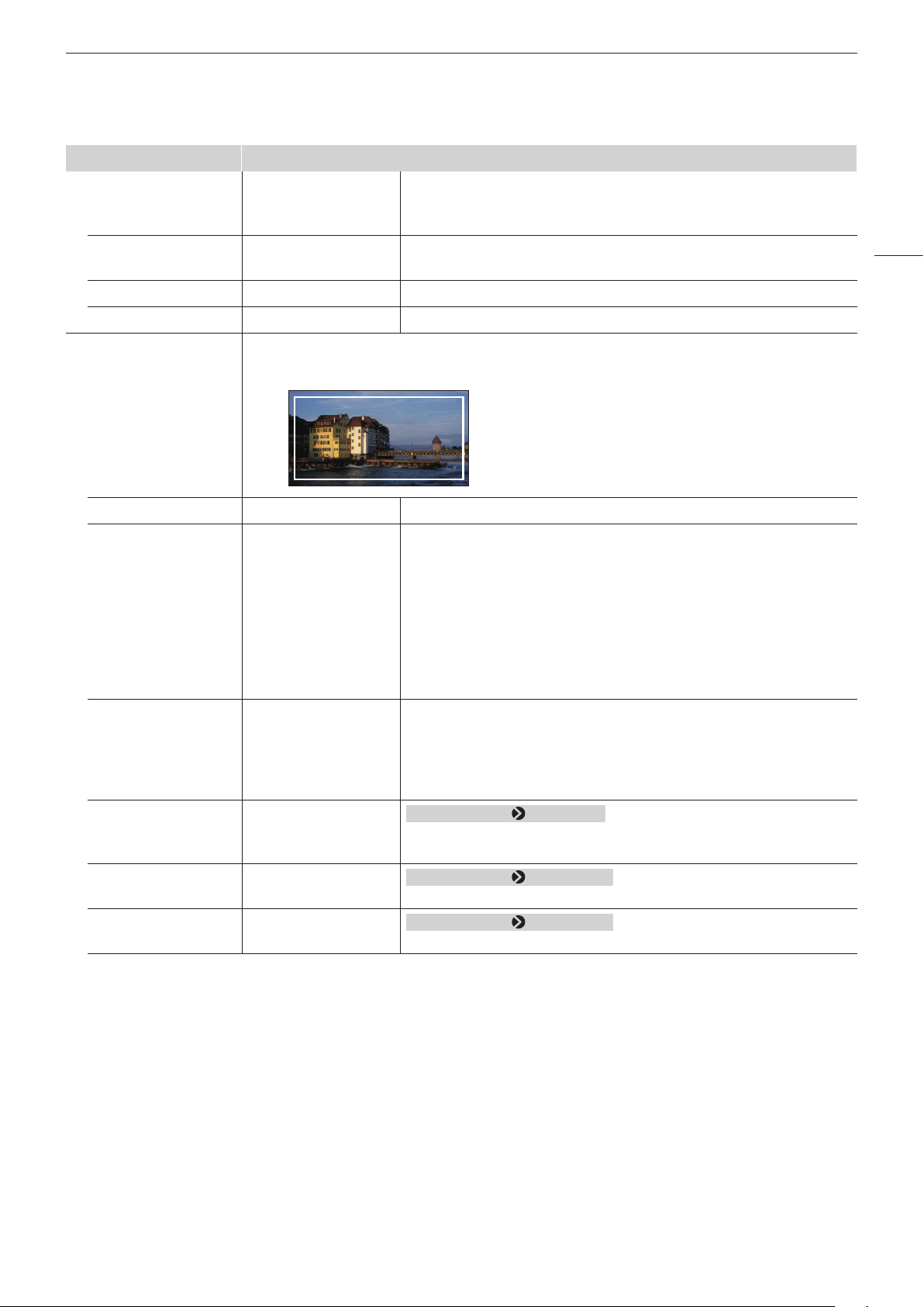
Sub Menu Setting Options (Bold: factory default)
Line Color White, Red, Green,
Sets the color of the aspect marker line.
Blue, Yellow, Cyan,
Magenta
Line Brightness High
Sets the brightness of the aspect marker line.
Low
H Position -65 to 65 (0) Changes horizontal position without changing the aspect.
V Position -35 to 35 (0) Changes vertical position without changing the aspect.
Safety Zone Marker 1, 2
1
There are two types of [Safety Zone Marker]: 1 and 2, which share the same settings. A safety zone
marker is used to set the safe zone of the image (actual displayed area) to check the image.
Enable On, Off Switches the safety zone marker On, Off.
Aspect Ratio
2
16:9, 15:9, 14:9, 13:9,
Sets the aspect ratio of the safety zone marker.
4:3, 2.39:1, 2.35:1,
1.896:1, 1.85:1, 1.66:1,
Variable
[Variable]: The aspect ratio can be entered as a numeric value (0.01:1
increments). The grayed out slider becomes active and can be used
to set the aspect ratio.
• When Variable is
selected
1.00:1 to 3.00:1
(1.78:1)
Area Size 80%, 88%, 90%, 93%,
Sets the safety zone marker area size.
Variable (%),
Variable (dot)
[Variable (%)]: The grayed out [Rate (%)] becomes active.
[Variable (dot)]: The grayed out [Width (dot)] and [Height (dot)] become
active.
OSD Menu
61
Rate (%) 50 to 100 (80)
Width (dot) 360 to 3840 (3072)
Height (dot) 240 to 2160 (1728)
When [Area Size] [Variable (%)]
Move the slider to set the displayed marker area size without changing the
aspect ratio in 1 % increments.
When [Area Size] [Variable (dot)]
Move the slider to set the area width in 2 dot increment.
When [Area Size] [Variable (dot)]
Move the slider to set the area height in 2 dot increment.
Page 62

62
OSD Menu
Sub Menu Setting Options (Bold: factory default)
Shape Box
Bracket
Enclosure
Sets the area shape of the safety zone marker.
[Box]:
[Bracket]:
[Enclosure]:
Line Width Thick
Normal
Thin
Line Color White, Red, Green,
Blue, Yellow, Cyan,
Magenta
Line Brightness High
Low
H Position -65 to 65 (0) Adjusts the marker horizontal position with the set aspect and size.
V Position -35 to 35 (0) Adjusts the marker vertical position with the set aspect and size.
Area Marker
1
[Area Marker] is used to check a specific area using a rectangular box.
Sets the width of the safety zone marker line.
Sets the color of the safety zone marker line.
Sets the brightness of the safety zone marker line.
Enable On, Off Switches the area marker On, Off.
H Position 0 to 3830 (240) Sets the start position (x-coordinate) to draw the rectangle. (in increments
of 2)
V Position 0 to 2150 (120) Sets the start position (y-coordinate) to draw the rectangle. (in increments
of 2)
Width (dot) 10 to 3840 (240) Sets the width of the rectangle. (in increments of 2)
Page 63

Sub Menu Setting Options (Bold: factory default)
Height (dot) 10 to 2160 (120) Sets the height of the rectangle. (in increments of 2)
Mask Black
Switches the mask color (in the marker).
Half
Off
OSD Menu
63
Line On, Off
When [Mask] [Black] or [Half]
Turns On/Off the outlines of the rectangular box.
Line Width Thick
Sets the width of the area marker line.
Normal
Thin
Line Color White, Red, Green,
Sets the color of the area marker line.
Blue, Yellow, Cyan,
Magenta
Line Brightness High
Sets the brightness of the area marker line.
Low
Center Marker
3
[Center Marker] shows the center of the image.
Enable On, Off Switches the center marker On, Off.
Size Large
Sets the size of the center marker.
Small
Line Width Thick
Sets the width of the center marker line.
Normal
Thin
Line Color White, Red, Green,
Sets the color of the center marker line.
Blue, Yellow, Cyan,
Magenta
Line Brightness High
Sets the brightness of the center marker line.
Low
Grid Marker
3
[Grid Marker] is marker used to check the horizontal and vertical position.
Enable On, Off Switches the grid marker On, Off.
Distance 160 dots
Sets the horizontal and vertical line distance.
240 dots
320 dots
Page 64

64
OSD Menu
Sub Menu Setting Options (Bold: factory default)
Line Width Thick
Normal
Thin
Line Color White, Red, Green,
Blue, Yellow, Cyan,
Magenta
Sets the width of the grid marker line.
Sets the color of the grid marker line.
Line Brightness High
Sets the brightness of the grid marker line.
Low
1
The marker is not displayed in the following cases:
-When there is no signal, unsupported signal, or a channel with [Input Configuration] not set is selected
-When an enlarged image is displayed
-During the execution of [Playback File] under [Screen Capture]
-When a [Test Pattern] is displayed
2
When [Area Size] is set to [Variable (dot)], you cannot select [Aspect Ratio].
3
The marker is not displayed in the following cases:
-When an enlarged image is displayed
Page 65

Function Settings
This menu is used to set functions to link with Cinema EOS cameras and video assistance functions.
OSD Menu
Sub Menu Setting Options (Bold: factory default)
Peaking
1
Customizes peakings which are assigned to Peaking 1 or Peaking 2. The outline is displayed in a
color, used to check the focus.
Enable Peaking 1
Peaking 2
Switches the peaking display mode and also sets peaking to Off.
Configures detailed settings for [Peaking 1] or [Peaking 2].
Off
Monochrome On, Off Displays video in monochrome.
Frequency
When [Enable]
Sets the central frequency of contour enhancement signals.
[Peaking 1]
Low
Middle
High
When [Enable]
[Peaking 2]
Low
Middle
High
Range -3 ~ +3 (0) Sets the width of the range to be colored.
Color White, Red, Green,
Sets the color to be used.
Blue, Yellow, Cyan,
Magenta
False Color
2
On, Off When set to [On], different colors are displayed according to video's
brightness level so that you can check the exposure condition easily.
Below are details of the chart. Numbers indicate the level of Y-signals.
65
Time Code
941 ~
877 ~
813 ~
749 ~
584 ~
420 ~
256 ~
192 ~
128 ~
64 ~
0 ~
3
Display the time code superimposed on the signal.
VITC01:23:45.05
1023
940
876
812
748
583
419
255
191
127
63
Enable On, Off Switches the time code display On, Off.
Type
4
VITC
Selects the type.
LTC
Red
Orange
Light orange
Yellow
Light gray
Medium gray
Dark gray
Blue
Blue purple
Light purple
Purple
Page 66
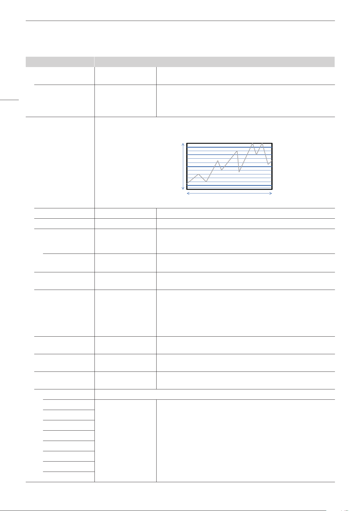
OSD Menu
66
Wave Form Monitor
Sub Menu Setting Options (Bold: factory default)
Size Large
Selects the size.
Small
Position
5
Top Left
Selects the display position.
Top Right
Bottom Left
Bottom Right
6
Configures various settings for the wave form monitor. On the wave form monitor, the horizontal axis
shows the horizontal resolution of the video and the vertical line shows the signal level.
255
Signal level
0
Horizontal resolution of video
Enable On, Off Switches the wave form monitor On, Off.
Select Signal Y, Cb, Cr, R, G, B Sets the waveform to be displayed.
Display Type All
Sets the display type.
Line
[Line]: The data for one line is displayed.
Select Line • When Line is selected
Selects the line to be displayed when [Line] is selected.
1 to 2160
Position
5
Bottom Left
Selects the display position.
Bottom Right
Scale Automatic
Sets the scale of the wave form monitor.
IRE
Canon Log
[Automatic]: Sets in accordance with the gamma settings.
Canon Log 2
Canon Log 3
SMPTE ST 2084
IRE
100 %
50 %
0%
-4%
Guide 1 to 255 A guide is displayed at the specified position. [Guide] is not displayed
when [255] is selected.
Standard Level High 190 to 255 Sets the standard display level (high). [Standard Level High] is not
displayed when [255] is selected.
Standard Level Low 0 to 64 Sets the standard display level (low). [Standard Level Low] is not displayed
when [0] is selected.
Color Sets the signals to be displayed and the color of signals exceeding the standard level.
Y White
Cb
Cr
R
G
Red
Green
Blue
Yellow
Cyan
Magenta
[Y], [Cb], [Cr], [R], [G], [B]: Selects the color of the selected signal.
Default value of each signal is shown below.
Y (White), Cb (White), Cr (White), R (Red), G (Green), B (Blue)
[Standard Level High], [Standard Level Low]: Selects the color of the
signal of the selected standard level.
Default value of each standard level is shown below.
Standard Level High (Magenta), Standard Level Low (Cyan)
B
Standard Level High
Standard Level Low
Page 67

Sub Menu Setting Options (Bold: factory default)
Vector Scope
OSD Menu
6
Configures various settings for the vector scope. Vector scope displays the intensity of color signals
and hue with the horizontal axis showing the color difference signal Cb and the vertical line showing
Cr.
(Cb, Cr) = (255, 255)
Red
Magenta
67
Yellow
Cr
Green
(Cb, Cr) = (0, 0)
Cyan
Cb
Enable On, Off Switches the vector scope On, Off.
Target 75%
Sets the target.
100%
Position
5
Bottom Left
Selects the display position.
Bottom Right
Audio Level Meter
7
Configures various settings for the audio level meter. Displays the audio level of the selected channel
number.
Enable On, Off Switches the audio level meter On, Off.
Channel Number
(SDI)
2CH
4CH
6CH
8CH
Sets the number of channels displayed when SDI signal is input. Options
change according to the setting for [SDI Group] under [Audio Settings].
When [SDI Group]
[CH1-CH8]
[2CH]: CH1 to CH2
[4CH]: CH1 to CH4
[6CH]: CH1 to CH6
[8CH]: CH1 to CH8
When [SDI Group] [CH9-CH16]
[2CH]: CH9 to CH10
[4CH]: CH9 to CH12
[6CH]: CH9 to CH14
[8CH]: CH9 to CH16
Channel Number
(HDMI)
2CH
4CH
6CH
8CH
Sets the number of channels displayed when HDMI signal is input.
[2CH]: CH1 to CH2
[4CH]: CH1 to CH4
[6CH]: CH1 to CH6
[8CH]: CH1 to CH8
Blue
Peak Hold On, Off One second of audio signal at the peak is kept.
Standard Level -40 to 0 (-20) Sets the standard level.
Page 68

68
OSD Menu
Sub Menu Setting Options (Bold: factory default)
Test Pattern
8
White, Gray (20%),
Sets the test pattern built into the main unit.
Black, Red, Green,
Blue, Ramp, 5 Step,
Color Bars, PLUGE, Off
Screen Capture
9
Captures the screen.
Capture Captures the screen. The data is saved under the name "YYYYMMDD_
hhmmss.bmp" in the root folder of the USB memory.
Frame Hold On, Off Pauses the video.
Capture Source All
Selects the sources to capture.
Video
[All]: Everything is captured including video assistance functions such as
markers and wave form monitor as well as OSD menu.
[Video]: Only video signals are captured.
Playback File
10
Select File
Plays back captured images.
Execute
[Select File]: Selects a file.
[Execute]: Plays back the image.
Finish Playback File Finishes playback.
Various Function Displays the function list to execute functions.
Monochrome On, Off
Blue Only
11
On, Off
Red Off On, Off
Green Off On, Off
Blue Off On, Off
Banner On, Off [Off]: The banner is displayed only when you press the jog dial while OSD
is closed.
Function Guide On, Off [On]: You can display the list of functions assigned to an F button on the
video display by pressing the jog dial while OSD is closed.
[Off]: Function guide is not displayed.
Page 69

Sub Menu Setting Options (Bold: factory default)
Camera Link
OSD Menu
Sets the functions to link with Cinema EOS cameras and ARRI cinema cameras.
Automatic Adjustment
(CINEMA EOS)
When [Picture Mode] [Canon Log]
Sets whether or not to link to the camera's image quality setting (when [SG-SDI RAW] is selected for
[Input Configuration] only).
On, Off Refer to the Setting Values Correspondence Table when [Color Gamut/
Gamma], [Color Temperature], and [Color Range] are all set to [On]. (
Color Gamut/Gamma On, Off The image quality of the display corresponds to the gamma and color
gamut of the camera.
Color Temperature On, Off The image quality of the display corresponds to the color temperature of
the camera.
Color Range On, Off The image quality of the display corresponds to the range of the camera.
Display Color Gamut ITU-R BT.709
ITU-R BT.2020
Sets the color gamut shown on the display when the camera's [Color
Space] is set to [Cinema Gamut] or [DCI-P3+].
DCI-P3
Automatic Adjustment
(ARRI)
When [Picture Mode] [User 1] to [User 7]
Sets whether or not to link to the camera's image quality setting.
On, Off
When [CDL/User LUT] [User LUT]
Refer to the Setting Values Correspondence Table when [ARRI LUT 709]
or [ARRI LUT 2020] are selected. (
71)
User LUT/Color Gamut On, Off The image quality of the display corresponds to the settings of [User LUT]
and color gamut of the camera.
Color Range On, Off The image quality of the display corresponds to the range of the camera.
Area Marker
13
Fan
12
ARRI Frame line 1A
ARRI Frame line 1B
Off
When an ARRI cinema camera is connected to this device, the [H Position],
[V Position], [Width], and [Height] for the [Area Marker] change depending
on the meta information.
On, Off Sets whether or not to stop the fan by linking with the camera's REC
signal. When [Fan Control] under [System Settings] is set to [On], the
mode changes so that the fan can be stopped, and when [Fan] is set to
[On], the fan can be stopped by linking with the camera's REC signal.
At room temperature (25 °C), the fan remains off for approximately one
minute (about 10 minutes when using DC power). The fan operates at a
faster speed than usual before and after the fan is stopped to lower the
internal temperature.
Camera Information Automatic
Sets conditions to display camera information.
On
Off
[Automatic]: Camera information is displayed for 4 seconds when the
information has changed.
[On]: Camera information is always displayed.
[Off]: Camera information is not displayed.
69
71)
1
[Peaking] cannot be displayed during the execution of [Playback File] under [Screen Capture].
2
[False Color] cannot be displayed during the execution of [Playback File] under [Screen Capture].
3
[Time Code] cannot be displayed in the following cases:
-When [Frame Hold] is [On]
-During the execution of [Playback File] under [Screen Capture]
-When the location selected for [Time Code] and [Audio Level Meter] to be displayed is the same
-When [Test Pattern] is displayed
4
This setting becomes invalid when HDMI signal is input and is fixed to [VITC].
5
This setting becomes invalid in the [Multi View (Dual)] display.
Page 70

OSD Menu
6
• [WaveFormMonitor]or[VectorScope]cannotbedisplayedinthefollowingcases:
-When an enlarged image is displayed
-When [Frame Hold] (during interlace signal or PsF signal) or [False Color] is [On]
-When [Peaking 1] or [Peaking 2] is selected
70
-During execution of [Playback File] under [Screen Capture]
-While [Test Pattern] is displayed
• Onlythesignalsetby[Marker/TC/WFM/VECInput]isdisplayedinthe[MultiView(Quad)]or[MultiView(Dual)]display.
• When[WaveFormMonitor]issetto[On],[VectorScope]turns[Off].When[VectorScope]issetto[On],[WaveFormMonitor]turns[Off].
7
[Audio Level Meter] cannot be displayed when [Frame Hold] is [On], during the execution of [Playback File] under [Screen Capture], or when [Test
Pattern] is displayed.
8
• Ifthepoweristurnedoffonceandthenbackon,thetestpatternwillnotbedisplayed.
• Thetestpatternwillbeerasedinthefollowingcases:
-When calibration has been started
-When the channel is changed using the CH button, F button assigned for Channel UP/Channel DOWN, or [Select Channel] under [Channel
Settings]
-When changing [Input Configuration] or [Select Input Signal] under [Channel Settings]
-When [Reset All Settings] is executed
9
Setting is disabled when [Multi View (Quad)] or [Multi View (Dual)] is selected.
10
When playing back captured images on other DP-V1710 or PC, color may not be played back precisely.
11
When [CDL/User LUT] is set to [User LUT], [Blue Only] cannot be selected.
12
This cannot be displayed when [Marker Preset] is [Off].
13
• Thiscanbeoperatedin[On]withRECsignalssupportedbythisfunction(CinemaEOScameras,Canonprofessional-usevideocameras,ARRI
cinema cameras).
• Ifthetemperatureinsidethemainunitincreaseswhilethefanisoff,themessage[Fanwillberotatedasthetemperatureishigh.]isdisplayed
and the fan starts rotating approximately ten seconds later. Since the temperature of the main unit has increased, the fan rotates faster than
usual.
• Thevideodisplay’sfanmaystartrotatingearlierthanthecamerabecausethetemperatureinsidethemainunithasincreased.
• Thefanmaynotstopinsomeconditions,forexamplewhenusedatahightemperature.
Page 71

Parameter of Cinema EOS cameras and DP-V1710
■
OSD Menu
Cinema EOS cameras
Color
Space
BT.709 Canon Log
BT.2020
Cinema
Gamut
DCI-P3+
BT.2020 Canon Log 2
Cinema
Gamut
Parameter of ARRI Cinema camera and DP-V1710
■
Gamma Color Gamut Gamma
ITU-R BT.709
ITU-R BT.2020 D65
Cinema Gamut to 709 D65
Cinema Gamut to 2020 D65
Cinema Gamut to DCI-P3 DCI-P3
DCI-P3+ to 709 D65
DCI-P3+ to DCI-P3 DCI-P3
ITU-R BT.2020
Cinema Gamut to 709 D65
Cinema Gamut to 2020 D65
Cinema Gamut to DCI-P3 DCI-P3
DP-V1710
Canon Log
Canon Log 2
Color
Temperature
D65
D65
Color Range
71
Automatic
ARRI Cinema camera DP-V1710
Color Space User LUT Color Gamut Color Range
REC 709 ARRI LUT 709 ITU-R BT.709 Automatic
REC 2020 ARRI LUT 2020 ITU-R BT.2020
(Limited 1)
Page 72

OSD Menu
System Settings
This menu is used to configure settings related the system of the video display.
72
Function/Channel Button Sets the function or channel to assign to the F buttons or CH button.
Language English
Date/Time Sets the year/month/date/hour/minute.
Network/Remote(GPI) Settings
Sub Menu Setting Options (Bold: factory default)
Display Function/
Display Function (CDL)
Display Channel Sets the channel to assign to the CH button on the display.
CH1 CH1 to CH20 (CH1) Select a CH button and register a channel number. A list of settings under
CH2 CH1 to CH20 (CH2)
CH3 CH1 to CH20 (CH3)
Network
In Monitor Display The video display supports Television Systems Ltd.’s “TSL UMD Protocol Ver. 5.0”. You can operate
1
Configure an IP
Address
Display 192.168.0.1
Subnet Mask 255.255.255.0
Control On, Off Sets whether to receive the control signal from the connected device.
Sets the function to assign to the F buttons of the main unit (
function from the following list ( 76).
the menu [Channel Settings] (
Sets the language of the OSD menu and messages.
日本語
简体中文
Configures settings for the network of the video display.
Automatic
Manual
the video display using an external device connected to the LAN terminal and display characters and
tally lights on the screen. You can specify the characters using up to 16 alpha-numerical characters
and symbols. (
35)
[Automatic]: Configures an IP address automatically with DHCP/Auto IP.
[Manual]: Configure an IP address and subnet mask manually.
33). Select an F button and assign a
53) is displayed.
Position Top
Bottom
This sets whether the characters and tally lights will be displayed at the
top or the bottom.
Page 73

Sub Menu Setting Options (Bold: factory default)
Remote(GPI)
2
You can operate the video display using an external controller such as a switcher that has been
connected to the REMOTE terminal. Operates while the GND (No. 8 Pin) is connected to No.s 1 to 7,
shorting them.
Pin1 CH1 to CH5
Pin2
Pin3
Pin4
Aspect Marker
Safety Zone Marker 1/2
Area Marker
Center Marker
Grid Marker
Pin5
Pin6
Pin7
Time Code
Wave Form Monitor
Vector Scope
Audio Level Meter
3
3
3
3
Assigns functions in each GPI pin. (
• Combining [Tally Green] and [Tally Red] makes [Tally Amber].
3
34)
Tally Green
Tally Red
Power On
4
— (Not set)
Display Name Sets the name of the main unit. You can input up to 16 alphanumeric characters.
OSD Menu
73
Power Indicator Brightness Off
1 to 5 (3)
Adjusts the brightness of the power indicator on the main unit. The greater
the number is, the greater the brightness.
Display Button LED On, Off Sets the F buttons and the lamp on the face.
Fan Settings Sets the operation of internal fan.
Fan Control On, Off Fan noise can be eliminated when the main unit is used during shooting or
when silent operation is needed.
Set this in advance to stop the fan manually or to stop the fan (
linking with the camera's REC signal. When this is set to [On], the mode
changes so that the fan can be stopped.
Fan Stop
5
On, Off If [Fan Stop] is set to [On] and when [Fan Control] is set to [On], the fan
can be stopped. At room temperature (25 °C), the fan remains off for
approximately one minute (about 10 minutes when using DC power).
The fan operates at a faster speed than usual before and after the fan is
stopped to lower the internal temperature.
Compatible Settings Sets the connection compatibility with HDMI equipment.
HDMI Normal
Compatible 1
Compatible 2
[Normal]: All formats are supported.
[Compatible 1]: Set this option when video is not played correctly in
[Normal]. HDR signals of a luminance higher than that of the display
main unit are not supported.
[Compatible 2]: Set this option when video is not played correctly in
[Normal] or [Compatible 1]. [4K50.00P/60.00P] and HDR signals are
not supported.
69) by
Page 74

OSD Menu
Sub Menu Setting Options (Bold: factory default)
Protect Settings Locks the settings so they cannot be changed. When you press the MENU button, [Signal/System
Information] appears, but other operations are grayed out because they are locked.
74
Password Set a password to protect settings. Use a four-digit number (0000 to
9999). The initial password is blank.
Protect Target You can remove Picture Mode and Select Channel from the items to be
protected.
Picture Mode On, Off [On]: Protects the [Picture Mode] settings.
[Off]: Removes the [Picture Mode] settings from protect target.
Select Channel On, Off [On]: Protects the [Select Channel] settings.
[Off]: Removes the [Select Channel] settings from protect target.
Protect Select [OK] to protect. When a password has been set, enter the
password and select [OK].
Unlocking Protect Settings
Move the selection frame to [Protect] and press the Jog dial for
approximately 3 seconds. When a password has been set, enter the
password and select [OK].
Firmware Update This function is used to update the video display firmware. Refer to the Canon website for detailed
information.
Export/Import
Export
6
Target USB
Sets the export/import main menu settings.
User 1 to User 3
Select the export destination.
[USB]: Export to a USB memory.
[User 1] to [User 3]: Export to the built-in memory of the main unit.
Filename Factory default is "dinfo_dpv1710.dat". You can change the name of the
file to be exported to the USB memory within 16 one-byte characters
including alphabetical characters, numbers, and symbols.
Execute Performs export.
Import
Target USB
User 1 to User 3
Filename Displays files with the extension ".dat" so you can select from among
Settings All
Adjustment
Channel Settings
Display Settings
Audio Settings
Marker Settings
Function Settings
System Settings
Execute Performs import.
Specify the destination to save the file to be imported.
them.
Select the settings to import.
Page 75

Sub Menu Setting Options (Bold: factory default)
Power on Setting Last memory
User 1 to User 3
OSD Menu
You can select the state of the display when the power is turned on.
[Last memory]: The video display starts up with the settings last used.
[User 1] to [User 3]: It starts up with the settings saved in [User 1] to [User 3]
under [Export].
75
Reset All Settings OK
Cancel
Returns all settings to factory default. When selected, the message [Reset
all settings to factory defaults?] appears.
[OK]: Performs reset.
[Cancel]: Returns to the previous screen without resetting.
1
Cannot be set when [Power on Setting] is [User 1] to [User 3].
2
This function will not work correctly in the following cases.
-If the same function is assigned to multiple pins.
-If the changes to the [Remote (GPI)] setting and the pin assignments were made when the pins were shorted.
3
The marker cannot be displayed when [Marker Preset] is set to [Off].
4
Can only be registered to [Pin7].
5
• Ifthemessage[Invalidoperationduetohightemperature.]isdisplayed,thefancannotbestoppedevenwhen[On]isselectedforthisitem.
Wait until the internal temperature lowers.
• Ifthetemperatureinsidethemainunitincreaseswhilethefanisoff,themessage[Fanwillberotatedasthetemperatureishigh.]isdisplayed
and the fan starts rotating approximately ten seconds later. Since the temperature of the main unit has increased, the fan rotates faster than
usual.
• Select[Off]torestartthefan.Thefanrotatesfasterthanusual.
• Thefanmaynotstopinsomeconditions,forexamplewhenusedatahightemperature.
6
• Thefollowingsettingscannotbeexportedorimported.
Adjustment Target values of Calibration (including calibration results)
Display Settings Zoom Preset, Frame Hold
Function Settings Test Pattern, Various Function (Monochrome, Blue Only, Red Off, Green Off, Blue Off)
System Settings Date/Time, Fan Stop, Export/Import, Power on Setting
• UserLUTdatacannotbeexportedorimportedto[User1]to[User3]under[Target].
• Dataexportedfromthisproductmaynotbeimportedtoproductsofwhichrmwareversionisearlierthantheversionofthisproduct.Toimport
data, update the firmware to the latest version.
Page 76
OSD Menu
Function to allow registration for the display F buttons (
■
72)
Item Options Item Options
Adjustment Picture Mode Gamma 1.0
76
Contrast 2.2
Brightness 2.35
Chroma 2.4
Chroma up 2.6
Sharpness ITU-R BT.1886
Backlight Control
1
Canon Log
Gamma Canon Log (HDR)
HDR Canon Log 2
HDR Range Canon Log 2 (HDR)
HDR/SDR View Canon Log 3
Gain Canon Log 3 (HDR)
Bias SMPTE ST 2084
xy Hybrid Log-Gamma Y
Picture Mode SMPTE-C Hybrid Log-Gamma RGB
EBU Gamma LUT 1 to Gamma LUT 8
ITU-R BT.709 CDL/User LUT CDL Preset
ITU-R BT.2020 User LUT
Adobe RGB CDL R
DCI-P3 CDL G
User 1 to User 7 CDL B
Canon Log CDL Slope
ACESproxy CDL Offset
Color Gamut SMPTE-C CDL Power
EBU CDL Saturation
ITU-R BT.709 CDL SOP/SAT
ITU-R BT.2020 CDL/User LUT Bypass
Adobe RGB CDL Export/Import
DCI-P3 Channel Settings Channel UP
Native Channel DOWN
Cinema Gamut to 709 Select Input Signal
Cinema Gamut to 2020 Audio Input
Cinema Gamut to DCI CH1 to CH20
DCI-P3+ to 709
DCI-P3+ to DCI
DCI-P3 to 709
ITU-R BT.2020 to 709
ACESproxy
Gamut LUT 1 to Gamut LUT 8
2
2
Page 77

OSD Menu
Item Options Item Options
Display Settings Screen Scalling Function Settings Peaking
Scaling Method Peaking 1
Zoom Preset Peaking 2
Zoom 1 Flase Color
Zoom 2 Capture
Zoom 3 Time Code
Frame Hold WFM/VEC
Audio Settings SDI Group Wave Form Monitor
CH L WFM Select Signal
CH R Vector Scope
Volume Audio Level Meter
Audio Switch Monochrome
Marker Settings
3
Marker Preset Blue Only
Marker 1 Red Off
Marker 2 Green Off
Marker 3 Blue Off
Marker 4 Camera Information
Marker 5 System Settings Hide OSD
4
Aspect Marker Fan Stop
Safety Zoon Marker 1
Safety Zoon Marker 2
Area Marker
Center Marker
Grid Marker
1
When the [Backlight Control] setting is switched using an F button, the information is applied to [Backlight Control] in [Picture Mode].
2
When changing channels with [Channel UP/DOWN], the channels with [Input Configuration] ( 53) set to [–] are skipped.
3
When any marker settings are changed using an F button, those changes will be applied to [Enable] under the currently selected [Marker Preset].
4
[Hide OSD] is a function to hide all OSD. When [On] is selected, OSD and [Separator] are hidden but the menu can be used.
77
Page 78

OSD Menu
Signal Information
Shows the signal information. When [Select Input Signal] is [Quad Input], information for the entire signal and each
input is displayed. Select a signal with the jog dial according to the guide at top right corner of the menu. When signal
information has been obtained although it is not displayed on the screen, the content of the information is grayed out.
78
SDI Signal HDMI Signal
Item Display Example Item Display Example
Channel
Input Configuration
Select Input Signal
Image Division
Format
Resolution
Picture Rate, I/P/PsF*
SDI Payload ID
Video Standard
Sampling Structure
Bit Depth
Picture Rate
Scanning Method
Link Number
CH1
6G/3G/HD-SDI (3G Level A)
Quad Input
Automatic
Automatic
4096x2160
24.00P
89 C3 46 01
3G-SDI
4:4:4:4 GBRA
10-bit
24.00
Progressive/Progressive
(Transport/Picture)
Single/Link_1
Channel
Input Configuration
Format
Resolution
Picture Rate, I/P/PsF
Pixel Encoding, Color Depth
Matrix
Range
EOTF
Max Luminance (Peak/Avg.)
Display Luminance (Max/Min)
White Point
Primary Color Red
Primary Color Green
Primary Color Blue
CH4
HDMI
Automatic
4096x2160
60.00P
4:2:2 YCbCr 10-bit
ITU-R BT.709
Full
SMPTE ST 2084
1000 / 500 cd/m
1000 - 0.005 cd/m
x=0.313, y=0.329
x=0.640, y=0.330
x=0.300, y=0.600
x=0.150, y=0.060
2
2
* When a content is grayed out, an asterisk [*] may be displayed indicating low [Picture Rate] accuracy such as [24.00P *].
System Information
Shows the video display status and network information.
Item Display Example
Display DP-V1710
Serial No. 000000000000
Firmware Ver. 1.0
Usage Time* 5 h
IP Address 192.168.0.1
Subnet Mask 255.255.255.0
MAC Address FF:FF:FF:FF:FF:FF
* The [Usage Time] is not always [0] when you purchase the display due to factory inspection.
Page 79

Main specifications/Performance
Panel
Panel Type IPS LCD panel
Screen Size 17.3 inch (43.8 cm)
Aspect Ratio 16:9
Resolution 3840x2160 (8.3 megapixels)
Active Display Area Approximately 381.9 x 214.8 mm
Pixel Pitch 99 µm/255 ppi
Image quality
Brightness (Standard) 100 cd/m
View Angle (Up, Down, Left, Right) 89° (contrast ratio 10 : 1 or higher)
Surface Treatment Anti-glare coating
General
Backlight Type LED, direct down type
Power
Power consumption
Environmental
Conditions
Operating
Rated Voltage: 100 – 240 V AC Rated Frequency: 50/60 Hz
At maximum load (including change in brightness through aging): Approximately 140 W
At factory shipment: Approximately 85 W
Temperature and humidity
Pressure: 700 – 1060 hPa
2
12 V DC Max. 10 A, XLR terminal
: 0 – 40 °C (32 – 104 °F), 20 – 85 %RH (no condensation)
recommended: 15 – 30 °C (59 – 86 °F)
79
Storage/
Transporting
Dimensions (width x height x depth) Including stands and handle: Approx. 435×356×194 mm (17.1×14.0×7.6 in.)
Weight Approximately 8 kg (17.6 lb)
Mounting Hole Pitch VESA standard 100 x 100 mm (3.9 x 3.9 in.)
Temperature and humidity
Pressure: 700 – 1060 hPa
Main unit only, excluding protrusions: Approx. 435×308×154 mm (17.1×12.1×6.1 in.)
: -20 – 40 ˚C (-4 – 104 °F), 20 – 85 %RH (no condensation)
41 – 60 ˚C (105 – 140 °F), 20 – 30 %RH (no condensation)
Page 80

Main specifications/Performance
Interface
Input 6G/3G/HD-SDI 4 (1 systems) BNC (75Ω) receptacle terminal
6G-SDI: Compliant with SMPTE 2081
3G-SDI: Compliant with SMPTE 2048-2/274M/296/372/425-5/425-3/425-1/
80
HD-SDI: Compliant with SMPTE 2048-2/274M/292-1/296/428-19/428-9
HDMI 1 (1 system) type A terminal Contents protection standard: HDCP 2.2
Output 6G/3G/HD-SDI 4 (1 pass-thru systems)
428-19/428-9
Head phone 1 stereo mini jack, Supported impedance: 32 Ω to 64
Others USB 1 USB A receptacle terminal
Universal Serial Bus Specification Revision 2.0 compliant LS (Low Speed)/FS (Full
Speed)/HS (High Speed) mode compatible
Compliant with Enhanced Host Controller Interface Specification for Universal Serial
Bus Revision 1.0
LAN 1 RJ-45 terminal
Compliant with IEEE802.3 10BASE-TX/IEEE802.3u 100BASE-TX
REMOTE 1 RJ-45 terminal, GPI 8 pins
Ω
Weight and dimensions are approximate. Error and omissions excepted.
The information in this manual is verified as of December 2016. It is subject to change without notice.
Page 81

Dimensions
Main specifications/Performance
Front
Rear
336 (13.2)
356 (14.0)
435 (17.1)
408.5 (16.1)
137 (5.4)
100 (3.9)
241.6 (9.5)
4-M4
Depth 6 (0.2) (Max.)
308 (12.1)
329 (13.0)
81
100 (3.9)
144.4 (5.7)
Side Bottom
26 (1.0)
91 (3.6)
61 (2.4)
51.5 (2.0)
160 (6.3)114.4 (4.5)
154 (6.1)
4-M4
Depth 7 (0.3) (Max.)
292 (11.5)
15 (0.6)
355.4 (14.0)
40 (1.6)
2- 4.5 (0.2)
3 (0.1)
Unit: mm (inch)
Page 82

Appendix
82
Supported Signal Format
SDI
Transmission method Signal format Color format Color depth Standards
HD-SDI 1280x720P 59.94/60.00 Hz 4:2:2 YCbCr 10-bit SMPTE 292-1
1280x720P 50.00 Hz
1280x720P 29.97/30.00 Hz
1280x720P 25.00 Hz
1280x720P 23.98/24.00 Hz
1920x1080i 59.94/60.00 Hz SMPTE 292-1
1920x1080i 50.00 Hz
SMPTE 296
SMPTE 274M
3G-SDI
(Level A)
1920x1080P 29.97/30.00 Hz
1920x1080PsF 29.97/30.00 Hz
1920x1080P 25.00 Hz
1920x1080PsF 25.00 Hz
1920x1080P 23.98/24.00 Hz
1920x1080PsF 23.98/24.00 Hz
2048x1080i 59.94/60.00 Hz
2048x1080i 50.00 Hz
2048x1080P 29.97/30.00 Hz SMPTE 292-1
2048x1080PsF 29.97/30.00 Hz
2048x1080P 25.00 Hz
2048x1080PsF 25.00 Hz
2048x1080P 23.98/24.00 Hz
2048x1080PsF 23.98/24.00 Hz
1280x720P 59.94/60.00 Hz 4:4:4 RGB
4:4:4 YCbCr
1280x720P 50.00 Hz 4:4:4 RGB
4:4:4 YCbCr
10-bit SMPTE 425-1
10-bit
SMPTE 428-9
SMPTE 428-19
SMPTE 2048-2
SMPTE 296
1280x720P 29.97/30.00 Hz 4:4:4 RGB
4:4:4 YCbCr
1280x720P 25.00 Hz 4:4:4 RGB
4:4:4 YCbCr
1280x720P 23.98/24.00 Hz 4:4:4 RGB
4:4:4 YCbCr
1920x1080P 59.94/60.00 Hz 4:2:2 YCbCr 10-bit SMPTE 425-1
10-bit
10-bit
10-bit
SMPTE 274M
Page 83

Appendix
Transmission method Signal format Color format Color depth Standards
3G-SDI
(Level A)
1920x1080i 59.94/60.00 Hz 4:4:4 RGB
4:4:4 YCbCr
12-bit/10-bit SMPTE 425-1
SMPTE 274M
4:2:2 YCbCr 12-bit
1920x1080P 50.00 Hz 4:2:2 YCbCr 10-bit
1920x1080i 50.00 Hz 4:4:4 RGB
4:4:4 YCbCr
4:2:2 YCbCr 12-bit
1920x1080P 29.97/30.00 Hz 4:4:4 RGB
4:4:4 YCbCr
4:2:2 YCbCr 12-bit
1920x1080PsF 29.97/30.00 Hz 4:4:4 RGB 10-bit
4:4:4 YCbCr 12-bit
4:4:4 YCbCr 10-bit SMPTE 425-1
4:2:2 YCbCr 12-bit
1920x1080P 25.00 Hz 4:4:4 RGB
4:4:4 YCbCr
4:2:2 YCbCr 12-bit
1920x1080PsF 25.00 Hz 4:4:4 RGB 10-bit
12-bit/10-bit
12-bit/10-bit
12-bit
12-bit/10-bit
12-bit
83
SMPTE 274M
4:4:4 YCbCr 12-bit
4:4:4 YCbCr 10-bit SMPTE 425-1
4:2:2 YCbCr 12-bit
1920x1080P 23.98/24.00 Hz 4:4:4 RGB
4:4:4 YCbCr
4:2:2 YCbCr 12-bit
1920x1080PsF 23.98/24.00 Hz 4:4:4 RGB 10-bit
4:4:4 YCbCr 12-bit
4:4:4 YCbCr 10-bit SMPTE 425-1
4:2:2 YCbCr 12-bit
2048x1080P 59.94/60.00 Hz 4:2:2 YCbCr 10-bit SMPTE 425-1
2048x1080i 59.94/60.00 Hz 4:4:4 RGB
4:4:4 YCbCr
4:4:4 X'Y'Z' 12-bit
4:2:2 YCbCr
12-bit/10-bit
12-bit
12-bit/10-bit
SMPTE 274M
SMPTE 274M
SMPTE 428-9
SMPTE 428-19
SMPTE 2048-2
2048x1080P 50.00 Hz 4:2:2 YCbCr 10-bit SMPTE 425-1
SMPTE 2048-2
Page 84

Appendix
Transmission method Signal format Color format Color depth Standards
3G-SDI
(Level A)
2048x1080i 50.00 Hz 4:4:4 RGB
4:4:4 YCbCr
12-bit/10-bit
84
4:4:4 X'Y'Z' 12-bit
4:2:2 YCbCr
2048x1080P 47.95/48.00 Hz 4:2:2 YCbCr 10-bit SMPTE 425-1
SMPTE 2048-2
2048x1080P 29.97/30.00 Hz 4:4:4 RGB 12-bit/10-bit SMPTE 425-1
SMPTE 428-9
4:4:4 X'Y'Z' 12-bit
4:4:4 YCbCr 12-bit/10-bit SMPTE 425-1
4:2:2 YCbCr 12-bit
2048x1080PsF 29.97/30.00 Hz 4:4:4 RGB 12-bit/10-bit SMPTE 425-1
4:4:4 X'Y'Z' 12-bit
4:4:4 YCbCr 12-bit/10-bit SMPTE 425-1
4:2:2 YCbCr 12-bit
2048x1080P 25.00 Hz 4:4:4 RGB 12-bit/10-bit SMPTE 425-1
4:4:4 X'Y'Z' 12-bit
4:4:4 YCbCr 12-bit/10-bit SMPTE 425-1
4:2:2 YCbCr 12-bit
SMPTE 428-19
SMPTE 2048-2
SMPTE 2048-2
SMPTE 428-9
SMPTE 428-19
SMPTE 2048-2
SMPTE 2048-2
SMPTE 428-9
SMPTE 428-19
SMPTE 2048-2
SMPTE 2048-2
2048x1080PsF 25.00 Hz 4:4:4 RGB 12-bit/10-bit SMPTE 425-1
4:4:4 X'Y'Z' 12-bit
4:4:4 YCbCr 12-bit/10-bit SMPTE 425-1
4:2:2 YCbCr 12-bit
2048x1080P 23.98/24.00 Hz 4:4:4 RGB 12-bit/10-bit SMPTE 425-1
4:4:4 X'Y'Z' 12-bit
4:4:4 YCbCr 12-bit/10-bit SMPTE 425-1
4:2:2 YCbCr 12-bit
2048x1080PsF 23.98/24.00 Hz 4:4:4 RGB 12-bit/10-bit SMPTE 425-1
4:4:4 X'Y'Z' 12-bit
4:4:4 YCbCr 12-bit/10-bit SMPTE 425-1
4:2:2 YCbCr 12-bit
SMPTE 428-9
SMPTE 428-19
SMPTE 2048-2
SMPTE 2048-2
SMPTE 428-9
SMPTE 428-19
SMPTE 2048-2
SMPTE 2048-2
SMPTE 428-9
SMPTE 428-19
SMPTE 2048-2
SMPTE 2048-2
Page 85

Appendix
Transmission method Signal format Color format Color depth Standards
3G-SDI
(Level B)
1920x1080P 59.94/60.00 Hz 4:2:2 YCbCr 10-bit SMPTE 425-1
1920x1080i 59.94/60.00 Hz 4:4:4 RGB
4:4:4 YCbCr
4:2:2 YCbCr 12-bit
1920x1080P 50.00 Hz 4:2:2 YCbCr 10-bit
12-bit/10-bit
SMPTE 372
SMPTE 274M
85
1920x1080i 50.00 Hz 4:4:4 RGB
4:4:4 YCbCr
4:2:2 YCbCr 12-bit
1920x1080P 29.97/30.00 Hz 4:4:4 RGB
4:4:4 YCbCr
4:2:2 YCbCr 12-bit
1920x1080PsF 29.97/30.00 Hz 4:4:4 RGB
4:4:4 YCbCr
4:2:2 YCbCr 12-bit
1920x1080P 25.00 Hz 4:4:4 RGB
4:4:4 YCbCr
4:2:2 YCbCr 12-bit
1920x1080PsF 25.00 Hz 4:4:4 RGB
4:4:4 YCbCr
4:2:2 YCbCr 12-bit
1920x1080P 23.98/24.00 Hz 4:4:4 RGB
4:4:4 YCbCr
4:2:2 YCbCr 12-bit
1920x1080PsF 23.98/24.00 Hz 4:4:4 RGB
4:4:4 YCbCr
12-bit/10-bit
12-bit/10-bit
12-bit/10-bit
12-bit/10-bit
12-bit/10-bit
12-bit/10-bit
12-bit/10-bit
4:2:2 YCbCr 12-bit
2048x1080P 59.94/60.00 Hz 4:2:2 YCbCr 10-bit SMPTE 425-1
SMPTE 372
SMPTE 428-9
SMPTE 428-19
SMPTE 2048-2
2048x1080i 59.94/60.00 Hz 4:4:4 RGB
4:4:4 YCbCr
4:4:4 X'Y'Z'
4:2:2 YCbCr
2048x1080P 50.00 Hz 4:2:2 YCbCr 10-bit SMPTE 425-1
2048x1080i 50.00 Hz 4:4:4 RGB
4:4:4 YCbCr
4:4:4 X'Y'Z'
4:2:2 YCbCr
12-bit/10-bit
12-bit
SMPTE 372
SMPTE 2048-2
12-bit/10-bit
12-bit
Page 86

Appendix
Transmission method Signal format Color format Color depth Standards
3G-SDI
(Level B)
86
2048x1080P 47.95/48.00 Hz 4:2:2 YCbCr 10-bit SMPTE 425-1
2048x1080P 29.97/30.00 Hz 4:4:4 RGB 12-bit/10-bit SMPTE 425-1
4:4:4 X'Y'Z' 12-bit
4:4:4 YCbCr 12-bit/10-bit SMPTE 425-1
4:2:2 YCbCr 12-bit
2048x1080PsF 29.97/30.00 Hz 4:4:4 RGB 12-bit/10-bit SMPTE 425-1
4:4:4 X'Y'Z' 12-bit
SMPTE 372
SMPTE 2048-2
SMPTE 372
SMPTE 428-9
SMPTE 428-19
SMPTE 2048-2
SMPTE 372
SMPTE 2048-2
SMPTE 372
SMPTE 428-9
SMPTE 428-19
SMPTE 2048-2
4:4:4 YCbCr 12-bit/10-bit SMPTE 425-1
4:2:2 YCbCr 12-bit
2048x1080P 25.00 Hz 4:4:4 RGB 12-bit/10-bit SMPTE 425-1
4:4:4 X'Y'Z' 12-bit
4:4:4 YCbCr 12-bit/10-bit SMPTE 425-1
4:2:2 YCbCr 12-bit
2048x1080PsF 25.00 Hz 4:4:4 RGB 12-bit/10-bit SMPTE 425-1
4:4:4 X'Y'Z' 12-bit
4:4:4 YCbCr 12-bit/10-bit SMPTE 425-1
4:2:2 YCbCr 12-bit
2048x1080P 23.98/24.00 Hz 4:4:4 RGB 12-bit/10-bit SMPTE 425-1
4:4:4 X'Y'Z' 12-bit
SMPTE 372
SMPTE 2048-2
SMPTE 372
SMPTE 428-9
SMPTE 428-19
SMPTE 2048-2
SMPTE 372
SMPTE 2048-2
SMPTE 372
SMPTE 428-9
SMPTE 428-19
SMPTE 2048-2
SMPTE 372
SMPTE 2048-2
SMPTE 372
SMPTE 428-9
SMPTE 428-19
SMPTE 2048-2
4:4:4 YCbCr 12-bit/10-bit SMPTE 425-1
4:2:2 YCbCr 12-bit
SMPTE 372
SMPTE 2048-2
Page 87

Appendix
Transmission method Signal format Color format Color depth Standards
3G-SDI
(Level B)
2048x1080PsF 23.98/24.00 Hz 4:4:4 RGB 12-bit/10-bit SMPTE 425-1
4:4:4 X'Y'Z' 12-bit
4:4:4 YCbCr 12-bit/10-bit SMPTE 425-1
4:2:2 YCbCr 12-bit
SMPTE 372
SMPTE 428-9
SMPTE 428-19
SMPTE 2048-2
SMPTE 372
SMPTE 2048-2
87
Dual Link 3G-SDI
(Level A)
Dual Link 3G-SDI
(Level B)
1920x1080P 59.94/60 Hz 4:4:4 RGB
4:4:4 YCbCr
4:2:2 YCbCr 12-bit
1920x1080P 50 Hz 4:4:4 RGB
4:4:4 YCbCr
4:2:2 YCbCr 12-bit
2048x1080P 59.94/60 Hz 4:4:4 RGB
4:4:4 YCbCr
4:4:4 X'Y'Z'
4:2:2 YCbCr
2048x1080P 50 Hz 4:4:4 RGB
4:4:4 YCbCr
4:4:4 X'Y'Z'
4:2:2 YCbCr
2048x1080P 47.95/48 Hz 4:4:4 RGB
4:4:4 YCbCr
4:4:4 X'Y'Z'
4:2:2 YCbCr
1920x1080P 59.94/60 Hz 4:4:4 RGB
4:4:4 YCbCr
4:2:2 YCbCr 12-bit
12-bit/10-bit SMPTE 425-3
SMPTE 274M
12-bit/10-bit
12-bit/10-bit SMPTE 425-3
SMPTE 428-9
12-bit
12-bit/10-bit
12-bit
12-bit/10-bit
12-bit
12-bit/10-bit SMPTE 425-3
SMPTE 428-19
SMPTE 2048-2
SMPTE 372
SMPTE 274M
1920x1080P 50 Hz 4:4:4 RGB
4:4:4 YCbCr
4:2:2 YCbCr 12-bit
2048x1080P 59.94/60 Hz 4:4:4 RGB
4:4:4 YCbCr
4:4:4 X'Y'Z'
4:2:2 YCbCr
2048x1080P 50 Hz 4:4:4 RGB
4:4:4 YCbCr
4:4:4 X'Y'Z'
4:2:2 YCbCr
2048x1080P 47.95/48 Hz 4:4:4 RGB
4:4:4 YCbCr
4:4:4 X'Y'Z'
4:2:2 YCbCr
12-bit/10-bit
12-bit/10-bit SMPTE 425-3
SMPTE 372
12-bit
12-bit/10-bit
12-bit
12-bit/10-bit
12-bit
SMPTE 428-9
SMPTE 428-19
SMPTE 2048-2
Page 88

Appendix
Transmission method Signal format Color format Color depth Standards
Dual Link 3G-SDI
Square Division
(Level B)
88
Dual Link 3G-SDI
2 Sample Interleave
(Level B)
3840x2160P 29.97/30 Hz 4:2:2 YCbCr 10-bit SMPTE 425-3
3840x2160PsF 29.97/30 Hz
3840x2160P 25 Hz
3840x2160PsF 25 Hz
3840x2160P 23.98/24 Hz
3840x2160PsF 23.98/24 Hz
4096x2160P 29.97/30 Hz SMPTE 425-3
4096x2160PsF 29.97/30 Hz
4096x2160P 25 Hz
4096x2160PsF 25 Hz
4096x2160P 23.98/24 Hz
4096x2160PsF 23.98/24 Hz
3840x2160P 29.97/30 Hz 4:2:2 YCbCr 10-bit SMPTE 425-3
3840x2160P 25 Hz
3840x2160P 23.98/24 Hz
SMPTE 372
SMPTE 274M
SMPTE 372
SMPTE 2048-2
SMPTE 372
SMPTE 274M
4096x2160P 29.97/30 Hz SMPTE 425-3
4096x2160P 25 Hz
4096x2160P 23.98/24 Hz
Quad Link HD-SDI 3840x2160i 59.94/60.00 Hz 4:2:2 YCbCr 10-bit SMPTE 292-1
3840x2160i 50.00 Hz
3840x2160P 29.97/30.00 Hz
3840x2160PsF 29.97/30.00 Hz
3840x2160P 25.00 Hz
3840x2160PsF 25.00 Hz
3840x2160P 23.98/24.00 Hz
3840x2160PsF 23.98/24.00 Hz
4096x2160i 59.94/60.00 Hz
4096x2160i 50.00 Hz
4096x2160P 29.97/30.00 Hz SMPTE 292-1
4096x2160PsF 29.97/30.00 Hz
4096x2160P 25.00 Hz
4096x2160PsF 25.00 Hz
SMPTE 372
SMPTE 2048-2
SMPTE 274M
SMPTE 428-9
SMPTE 428-19
SMPTE 2048-2
4096x2160P 23.98/24.00 Hz
4096x2160PsF 23.98/24.00 Hz
Page 89

Appendix
Transmission method Signal format Color format Color depth Standards
Quad Link 3G-SDI
(Level A)
3840x2160P 59.94/60.00 Hz 4:2:2 YCbCr 10-bit SMPTE 425-1
3840x2160i 59.94/60.00 Hz 4:4:4 RGB
4:4:4 YCbCr
4:2:2 YCbCr 12-bit
3840x2160P 50.00 Hz 4:2:2 YCbCr 12-bit
12-bit/10-bit
SMPTE 274M
89
3840x2160i 50.00 Hz 4:4:4 RGB
4:4:4 YCbCr
4:2:2 YCbCr 12-bit
3840x2160P 29.97/30.00 Hz 4:4:4 RGB
4:4:4 YCbCr
4:2:2 YCbCr 12-bit
3840x2160PsF 29.97/30.00 Hz 4:4:4 RGB 10-bit
4:4:4 YCbCr 12-bit
4:4:4 YCbCr 10-bit SMPTE 425-1
4:2:2 YCbCr 12-bit
3840x2160P 25.00 Hz 4:4:4 RGB
4:4:4 YCbCr
4:2:2 YCbCr 12-bit
3840x2160PsF 25.00 Hz 4:4:4 RGB 10-bit
4:4:4 YCbCr 12-bit
4:4:4 YCbCr 10-bit SMPTE 425-1
4:2:2 YCbCr 12-bit
12-bit/10-bit
12-bit/10-bit
12-bit
12-bit/10-bit
12-bit
SMPTE 274M
SMPTE 274M
3840x2160P 23.98/24.00 Hz 4:4:4 RGB
4:4:4 YCbCr
4:2:2 YCbCr 12-bit
3840x2160PsF 23.98/24.00 Hz 4:4:4 RGB 10-bit
4:4:4 YCbCr 12-bit
4:4:4 YCbCr 10-bit SMPTE 425-1
4:2:2 YCbCr 12-bit
4096x2160P 59.94/60.00 Hz 4:2:2 YCbCr 10-bit SMPTE 425-1
4096x2160i 59.94/60.00 Hz 4:4:4 RGB
4:4:4 YCbCr
4:4:4 X'Y'Z'
4:2:2 YCbCr
12-bit/10-bit
12-bit
SMPTE 274M
SMPTE 428-9
SMPTE 428-19
SMPTE 2048-2
12-bit/10-bit
12-bit
Page 90

Appendix
Transmission method Signal format Color format Color depth Standards
Quad Link 3G-SDI
(Level A)
4096x2160P 50.00 Hz 4:2:2 YCbCr 10-bit SMPTE 425-1
SMPTE 2048-2
90
4096x2160i 50.00 Hz 4:4:4 RGB
4:4:4 YCbCr
4:4:4 X'Y'Z'
4:2:2 YCbCr
4096x2160P 47.95/48.00 Hz 4:2:2 YCbCr 10-bit SMPTE 425-1
4096x2160P 29.97/30.00 Hz 4:4:4 RGB 12-bit/10-bit SMPTE 425-1
4:4:4 X'Y'Z' 12-bit
4:4:4 YCbCr 12-bit/10-bit SMPTE 425-1
4:2:2 YCbCr 12-bit
4096x2160PsF 29.97/30.00 Hz 4:4:4 RGB 12-bit/10-bit SMPTE 425-1
4:4:4 X'Y'Z' 12-bit
4:4:4 YCbCr 12-bit/10-bit SMPTE 425-1
4:2:2 YCbCr 12-bit
4096x2160P 25.00 Hz 4:4:4 RGB 12-bit/10-bit SMPTE 425-1
4:4:4 X'Y'Z' 12-bit
12-bit/10-bit
12-bit
SMPTE 2048-2
SMPTE 428-9
SMPTE 428-19
SMPTE 2048-2
SMPTE 2048-2
SMPTE 428-9
SMPTE 428-19
SMPTE 2048-2
SMPTE 2048-2
SMPTE 428-9
SMPTE 428-19
SMPTE 2048-2
4:4:4 YCbCr 12-bit/10-bit SMPTE 425-1
4:2:2 YCbCr 12-bit
4096x2160PsF 25.00 Hz 4:4:4 RGB 12-bit/10-bit SMPTE 425-1
4:4:4 X'Y'Z' 12-bit
4:4:4 YCbCr 12-bit/10-bit SMPTE 425-1
4:2:2 YCbCr 12-bit
4096x2160P 23.98/24.00 Hz 4:4:4 RGB 12-bit/10-bit SMPTE 425-1
4:4:4 X'Y'Z' 12-bit
4:4:4 YCbCr 12-bit/10-bit SMPTE 425-1
4:2:2 YCbCr 12-bit
4096x2160PsF 23.98/24.00 Hz 4:4:4 RGB 12-bit/10-bit SMPTE 425-1
4:4:4 X'Y'Z' 12-bit
4:4:4 YCbCr 12-bit/10-bit SMPTE 425-1
4:2:2 YCbCr 12-bit
SMPTE 2048-2
SMPTE 428-9
SMPTE 428-19
SMPTE 2048-2
SMPTE 2048-2
SMPTE 428-9
SMPTE 428-19
SMPTE 2048-2
SMPTE 2048-2
SMPTE 428-9
SMPTE 428-19
SMPTE 2048-2
SMPTE 2048-2
Page 91
Appendix
Transmission method Signal format Color format Color depth Standards
Quad Link 3G-SDI
2 Sample Interleave
(Level A)
3840x2160P 59.94/60 Hz 4:2:2 YCbCr 10-bit SMPTE 425-5
3840x2160P 50 Hz 4:2:2 YCbCr 10-bit
3840x2160P 29.97/30 Hz 4:4:4 RGB
4:4:4 YCbCr
4:2:2 YCbCr 12-bit
12-bit/10-bit
SMPTE 274M
91
3840x2160P 25 Hz 4:4:4 RGB
4:4:4 YCbCr
4:2:2 YCbCr 12-bit
3840x2160P 23.98/24 Hz 4:4:4 RGB
4:4:4 YCbCr
4:2:2 YCbCr 12-bit
4096x2160P 59.94/60 Hz 4:2:2 YCbCr 10-bit SMPTE 425-5
4096x2160P 50 Hz 4:2:2 YCbCr 10-bit
4096x2160P 47.95/48 Hz 4:2:2 YCbCr 10-bit
4096x2160P 29.97/30 Hz 4:4:4 RGB 12-bit/10-bit
4:4:4 X'Y'Z' 12-bit
4:4:4 YCbCr 12-bit/10-bit
4:2:2 YCbCr 12-bit
4096x2160P 25 Hz 4:4:4 RGB 12-bit/10-bit
4:4:4 X'Y'Z' 12-bit
4:4:4 YCbCr 12-bit/10-bit
4:2:2 YCbCr 12-bit
4096x2160P 23.98/24 Hz 4:4:4 RGB 12-bit/10-bit
12-bit/10-bit
12-bit/10-bit
SMPTE 428-9
SMPTE 428-19
SMPTE 2048-2
Quad Link 3G-SDI
(Level B)
4:4:4 X'Y'Z' 12-bit
4:4:4 YCbCr 12-bit/10-bit
4:2:2 YCbCr 12-bit
3840x2160P 59.94/60.00 Hz 4:2:2 YCbCr 10-bit SMPTE 425-1
3840x2160i 59.94/60.00 Hz 4:4:4 RGB
4:4:4 YCbCr
4:2:2 YCbCr 12-bit
3840x2160P 50.00 Hz 4:2:2 YCbCr 10-bit
12-bit/10-bit
SMPTE 372
SMPTE 274M
Page 92
Appendix
Transmission method Signal format Color format Color depth Standards
Quad Link 3G-SDI
(Level B)
92
3840x2160i 50.00 Hz 4:4:4 RGB
4:4:4 YCbCr
4:2:2 YCbCr 12-bit
3840x2160P 29.97/30.00 Hz 4:4:4 RGB
4:4:4 YCbCr
4:2:2 YCbCr 12-bit
12-bit/10-bit SMPTE 425-1
12-bit/10-bit
SMPTE 372
SMPTE 274M
3840x2160PsF 29.97/30.00 Hz 4:4:4 RGB
4:4:4 YCbCr
4:2:2 YCbCr 12-bit
3840x2160P 25.00 Hz 4:4:4 RGB
4:4:4 YCbCr
4:2:2 YCbCr 12-bit
3840x2160PsF 25.00 Hz 4:4:4 RGB
4:4:4 YCbCr
4:2:2 YCbCr 12-bit
3840x2160P 23.98/24.00 Hz 4:4:4 RGB
4:4:4 YCbCr
4:2:2 YCbCr 12-bit
3840x2160PsF 23.98/24.00 Hz 4:4:4 RGB
4:4:4 YCbCr
4:2:2 YCbCr 12-bit
4096x2160P 59.94/60.00 Hz 4:2:2 YCbCr 10-bit SMPTE 425-1
12-bit/10-bit
12-bit/10-bit
12-bit/10-bit
12-bit/10-bit
12-bit/10-bit
SMPTE 372
SMPTE 428-9
SMPTE 428-19
SMPTE 2048-2
4096x2160i 59.94/60.00 Hz 4:4:4 RGB
4:4:4 YCbCr
4:4:4 X'Y'Z'
4:2:2 YCbCr
4096x2160P 50.00 Hz 4:2:2 YCbCr 10-bit SMPTE 425-1
4096x2160i 50.00 Hz 4:4:4 RGB
4:4:4 YCbCr
4:4:4 X'Y'Z'
4:2:2 YCbCr
4096x2160P 47.95/48.00 Hz 4:2:2 YCbCr 10-bit SMPTE 425-1
12-bit/10-bit
12-bit
SMPTE 372
SMPTE 2048-2
12-bit/10-bit
12-bit
SMPTE 372
SMPTE 2048-2
Page 93

Appendix
Transmission method Signal format Color format Color depth Standards
Quad Link 3G-SDI
(Level B)
4096x2160P 29.97/30.00 Hz 4:4:4 RGB 12-bit/10-bit SMPTE 425-1
SMPTE 372
4:4:4 X'Y'Z' 12-bit
4:4:4 YCbCr 12-bit/10-bit SMPTE 425-1
4:2:2 YCbCr 12-bit
4096x2160PsF 29.97/30.00 Hz 4:4:4 RGB 12-bit/10-bit SMPTE 425-1
4:4:4 X'Y'Z' 12-bit
4:4:4 YCbCr 12-bit/10-bit SMPTE 425-1
4:2:2 YCbCr 12-bit
SMPTE 428-9
SMPTE 428-19
SMPTE 2048-2
SMPTE 372
SMPTE 2048-2
SMPTE 372
SMPTE 428-9
SMPTE 428-19
SMPTE 2048-2
SMPTE 372
SMPTE 2048-2
93
4096x2160P 25.00 Hz 4:4:4 RGB 12-bit/10-bit SMPTE 425-1
4:4:4 X'Y'Z' 12-bit
4:4:4 YCbCr 12-bit/10-bit SMPTE 425-1
4:2:2 YCbCr 12-bit
4096x2160PsF 25.00 Hz 4:4:4 RGB 12-bit/10-bit SMPTE 425-1
4:4:4 X'Y'Z' 12-bit
4:4:4 YCbCr 12-bit/10-bit SMPTE 425-1
4:2:2 YCbCr 12-bit
4096x2160P 23.98/24.00 Hz 4:4:4 RGB 12-bit/10-bit SMPTE 425-1
4:4:4 X'Y'Z' 12-bit
SMPTE 372
SMPTE 428-9
SMPTE 428-19
SMPTE 2048-2
SMPTE 372
SMPTE 2048-2
SMPTE 372
SMPTE 428-9
SMPTE 428-19
SMPTE 2048-2
SMPTE 372
SMPTE 2048-2
SMPTE 372
SMPTE 428-9
SMPTE 428-19
SMPTE 2048-2
4:4:4 YCbCr 12-bit/10-bit SMPTE 425-1
4:2:2 YCbCr 12-bit
SMPTE 372
SMPTE 2048-2
Page 94

Appendix
Transmission method Signal format Color format Color depth Standards
Quad Link 3G-SDI
(Level B)
4096x2160PsF 23.98/24.00 Hz 4:4:4 RGB 12-bit/10-bit SMPTE 425-1
4:4:4 X'Y'Z' 12-bit
94
4:4:4 YCbCr 12-bit/10-bit SMPTE 425-1
4:2:2 YCbCr 12-bit
Quad Link 3G-SDI
2 Sample Interleave
(Level B)
3840x2160P 59.94/60 Hz 4:2:2 YCbCr 10-bit SMPTE 425-5
3840x2160P 50 Hz 4:2:2 YCbCr 10-bit
3840x2160P 29.97/30 Hz 4:4:4 RGB
4:4:4 YCbCr
4:2:2 YCbCr 12-bit
12-bit/10-bit
SMPTE 372
SMPTE 428-9
SMPTE 428-19
SMPTE 2048-2
SMPTE 372
SMPTE 2048-2
SMPTE 372
SMPTE 274M
3840x2160P 25 Hz 4:4:4 RGB
4:4:4 YCbCr
4:2:2 YCbCr 12-bit
3840x2160P 23.98/24 Hz 4:4:4 RGB
4:4:4 YCbCr
4:2:2 YCbCr 12-bit
4096x2160P 59.94/60 Hz 4:2:2 YCbCr 10-bit SMPTE 425-5
4096x2160P 50 Hz 4:2:2 YCbCr 10-bit
4096x2160P 47.95/48 Hz 4:2:2 YCbCr 10-bit
4096x2160P 29.97/30 Hz 4:4:4 RGB 12-bit/10-bit
4:4:4 X'Y'Z' 12-bit
4:4:4 YCbCr 12-bit/10-bit
4:2:2 YCbCr 12-bit
4096x2160P 25 Hz 4:4:4 RGB 12-bit/10-bit
4:4:4 X'Y'Z' 12-bit
4:4:4 YCbCr 12-bit/10-bit
4:2:2 YCbCr 12-bit
4096x2160P 23.98/24 Hz 4:4:4 RGB 12-bit/10-bit
12-bit/10-bit
12-bit/10-bit
SMPTE 372
SMPTE 428-9
SMPTE 428-19
SMPTE 2048-2
4:4:4 X'Y'Z' 12-bit
4:4:4 YCbCr 12-bit/10-bit
4:2:2 YCbCr 12-bit
6G-SDI 3840x2160P 29.97/30.00 Hz 4:2:2 YCbCr 10-bit SMPTE 2081-10
3840x2160P 25.00 Hz
3840x2160P 23.98/24.00 Hz
4096x2160P 25.00 Hz
4096x2160P 23.98/24.00 Hz
Dual Link 6G-SDI
Square Division,
2 Sample Interleave
3840x2160P 59.94/60.00 Hz 4:2:2 YCbCr 10-bit SMPTE 2081-11
3840x2160P 50.00 Hz
Page 95

RAW
Signal format
3840x2160P 59.94 Hz, 50.00 Hz, 29.97 Hz, 25.00 Hz, 24.00 Hz, 23.98 Hz
4096x2160P 59.94 Hz, 50.00 Hz, 29.97 Hz, 25.00 Hz, 24.00 Hz, 23.98 Hz
HDMI
Signal format Color format/Color depth
640x480P 59.94/60.00 Hz 4:4:4 RGB 8-bit
800x600P 60.00 Hz
1024x768P 60.00 Hz
720x480P 59.94/60.00 Hz 4:4:4 RGB 12-bit/10-bit/8-bit
720x576P 50.00 Hz
1280x720P 59.94/60.00 Hz
1280x720P 50.00 Hz
4:4:4 YCbCr 12-bit/10-bit/8-bit
4:2:2 YCbCr 12-bit
Appendix
95
1920x1080P 59.94/60.00 Hz
1920x1080i 59.94/60.00 Hz
1920x1080P 50.00 Hz
1920x1080i 50.00 Hz
1920x1080P 29.97/30.00 Hz
1920x1080P 25.00 Hz
1920x1080P 23.98/24.00 Hz
2048x1080P 59.94/60.00 Hz
2048x1080P 50.00 Hz
2048x1080P 29.97/30.00 Hz
2048x1080P 25.00 Hz
2048x1080P 23.98/24.00 Hz
3840x2160P 59.94/60.00 Hz 4:4:4 RGB 8-bit
3840x2160P 50.00 Hz
3840x2160P 29.97/30.00 Hz 4:4:4 RGB 12-bit/10-bit/8-bit
3840x2160P 25.00 Hz
3840x2160P 23.98/24.00 Hz
4:4:4 YCbCr 8-bit
4:2:2 YCbCr 12-bit
4:2:0 YCbCr 12-bit/10-bit/8-bit
4:4:4 YCbCr 12-bit/10-bit/8-bit
4:2:2 YCbCr 12-bit
4096x2160P 59.94/60.00 Hz 4:4:4 RGB 8-bit
4096x2160P 50.00 Hz
4096x2160P 29.97/30.00 Hz 4:4:4 RGB 12-bit/10-bit/8-bit
4096x2160P 25.00 Hz
4096x2160P 23.98/24.00 Hz
4:4:4 YCbCr 8-bit
4:2:2 YCbCr 12-bit
4:2:0 YCbCr 12-bit/10-bit/8-bit
4:4:4 YCbCr 12-bit/10-bit/8-bit
4:2:2 YCbCr 12-bit
Page 96

Appendix
Image/Frame Display
SDI
96
1280x720 23.98/24.00 P 47.96/48.00 P*
1920x1080 50.00 i 50.00 P
2048x1080 50.00 i 50.00 P
Signal system Display Method
25.00 P 50.00 P*
29.97/30.00 P 59.94/60.00 P*
50.00 P 50.00 P
59.94/60.00 P 59.94/60.00 P
59.94/60.00 i 59.94/60.00 P
23.98/24.00 PsF 47.96/48.00 P*
25.00 PsF 50.00 P*
29.97/30.00 PsF 59.94/60.00 P*
23.98/24.00 P 47.96/48.00 P*
25.00 P 50.00 P*
29.97/30.00 P 59.94/60.00 P*
50.00 P 50.00 P
59.94/60.00 P 59.94/60.00 P
59.94/60.00 i 59.94/60.00 P
23.98/24.00 PsF 47.96/48.00 P*
25.00 PsF 50.00 P*
29.97/30.00 PsF 59.94/60.00 P*
23.98/24.00 P 47.96/48.00 P*
25.00 P 50.00 P*
29.97/30.00 P 59.94/60.00 P*
47.95/48.00 P 47.95/48.00 P
50.00 P 50.00 P
59.94/60.00 P 59.94/60.00 P
3840x2160 50.00 i 50.00 P
59.94/60.00 i 59.94/60.00 P
23.98/24.00 PsF 47.96/48.00 P*
25.00 PsF 50.00 P*
29.97/30.00 PsF 59.94/60.00 P*
23.98/24.00 P 47.96/48.00 P*
25.00 P 50.00 P*
29.97/30.00 P 59.94/60.00 P*
50.00 P 50.00 P
59.94/60.00 P 59.94/60.00 P
Page 97

Signal system Display Method
4096x2160 50.00 i 50.00 P
59.94/60.00 i 59.94/60.00 P
Appendix
23.98/24.00 PsF 47.96/48.00 P*
25.00 PsF 50.00 P*
29.97/30.00 PsF 59.94/60.00 P*
23.98/24.00 P 47.96/48.00 P*
25.00 P 50.00 P*
29.97/30.00 P 59.94/60.00 P*
47.95/48.00 P 47.95/48.00 P
50.00 P 50.00 P
59.94/60.00 P 59.94/60.00 P
* : Displaying same frame
97
Page 98
Appendix
HDMI
Signal system Display Method
640x480 59.94/60.00 P 59.94/60.00 P
98
800x600 60.00 P 60.00 P
720x480 59.94/60.00 P 59.94/60.00 P
720x576 50.00 P 50.00 P
1024x768 60.00 P 60.00 P
1280x720 59.94/60.00 P 59.94/60.00 P
1280x720 50.00 P 50.00 P
1920x1080 59.94/60.00 P 59.94/60.00 P
1920x1080 59.94/60.00 i 59.94/60.00 P
1920x1080 50.00 P 50.00 P
1920x1080 50.00 i 50.00 P
1920x1080 29.97/30.00 P 59.94/60.00 P*
1920x1080 25.00 P 50.00 P*
1920x1080 23.98/24.00 P 47.96/48.00 P*
2048x1080 59.94/60.00 P 59.94/60.00 P
2048x1080 50.00 P 50.00 P
2048x1080 29.97/30.00 P 59.94/60.00 P*
2048x1080 25.00 P 50.00 P*
2048x1080 23.98/24.00 P 47.96/48.00 P*
3840x2160 59.94/60.00 P 59.94/60.00 P
3840x2160 50.00 P 50.00 P
3840x2160 29.97/30.00 P 59.94/60.00 P*
3840x2160 25.00 P 50.00 P*
3840x2160 23.98/24.00 P 47.96/48.00 P*
4096x2160 59.94/60.00 P 59.94/60.00 P
4096x2160 50.00 P 50.00 P
4096x2160 29.97/30.00
4096x2160 25.00 P 50.00 P*
4096x2160 23.98/24.00 P 47.96/48.00 P*
P 59.94/60.00 P*
* : Displaying same frame
Page 99
Error Messages
Message Description and Action
Calibration Failed to initialize the external sensor. See CA-310 and CA-210 instruction manual.
Calibration error. • Check the installation and connection of the
external sensor and retry (
• Perform matrix calibration of CA-310 and CA-210
(
28).
Calibration is completed.
(Brightness setting is lower than target brightness.)
Failed to detect the external sensor.
Please check the connection with the sensor.
Network Communication error. IP address may be in conflict or there may be a
Invalid IP Address. Enter the correct IP address.
Invalid Subnet Mask. Enter the correct subnet mask.
Various settings,
CDL export
LUT, Various settings,
CDL import
The USB memory is full. Use another USB memory or delete the content of
Failed to write file. The USB memory may be defective or protected.
(LUT Import) "LUT Type" is different.
(CDL Import) "File Type" is different.
Set the [Luminance] in calibration again ( 46).
Correctly connect the external sensor to the USB
port of this main unit.
network communication error. Check the network
environment.
the memory.
Check the USB memory.
Select the correct file format.
28).
99
Failed to read file. The USB memory may be defective or protected.
Check the USB memory.
Failed to import. There is an error in the file to be imported. Check the
file.
No import file. Check and ensure that the file has been saved to the
USB memory or imported to [User 1] to [User 3].
Page 100
Error Messages
Message Description and Action
Screen Capture Failed to capture. The USB memory may be defective or protected.
Check the USB memory.
100
Invalid Signal. A screen displaying no video is being captured for
example there is no signal or an unsupported signal
is being input. Check the signal, input it again, and
capture it.
Copy protected signal. The signal you tried to capture may be protected by
HDCP 2.2 which is a copy prevention standard for
HDMI. In this case, the signal cannot be captured.
Check the HDMI signal.
Failed to playback file. The USB memory or the file may be defective or
protected. Check the USB memory or the file.
No capture file. Check and ensure that the file has been saved to the
USB memory.
Hardware error Backlight error. Disconnect the power cord, reconnect it, and then
Fan error.
Panel error.
I/F error.
System error.
Invalid operation due to high temperature. The temperature inside the main unit is high. Turn off
Input signal No Signal Displayed when there is no video signal input.
turn on the power.
If the message persists, contact Canon Customer
Center.
the power and wait until the fan stops.
Unsupported Unsupported video signal is input. Check the
supported signal format (
"Input Configuration" is different from Payload. Check the [Input Configuration] ( 53) and [Signal
Information] ( 78) settings. Reset any incorrect [Input
Configuration] settings.
Operation Invalid operation. Operation is disabled. Check the setting items.
"Protect Settings" is on. To use the OSD menu, move the selection frame
to [Protect] and press the jog dial for approximately 3
seconds.
"CDL/User LUT Bypass" is on. When [CDL/User LUT Bypass] is turned [On], you
cannot adjust [Power], [Saturation], [Offset], or
[Slope].
Invalid Password. Enter the correct password.
USB memory USB memory is not connected. Correctly connect the USB memory to the USB port
of this main unit.
Unsupported USB memory. Check the USB memory format and make sure it is
not protected.
82).
 Loading...