

Canon CANOSCAN FB1210U Service Manual

COPYRIGHT © 2000 CANON INC. CANOSCAN FB1210U REV.0 APR. 2000 PRINTED IN JAPAN (IMPRIME AU JAPON)
APR. 2000
JY8-1316-00Z
REVISION 0
SERVICE
MANUAL

COPYRIGHT © 2000 CANON INC. CANOSCAN FB1210U REV.0 APR. 2000 PRINTED IN JAPAN (IMPRIME AU JAPON)
COPYRIGHT © 2000 CANON INC.
Printed in Japan
Imprimè au Japon
Use of this manual should be strictly supervised
to avoid disclosure of confidential information.

COPYRIGHT © 2000 CANON INC. CANOSCAN FB1210U REV.0 APR. 2000 PRINTED IN JAPAN (IMPRIME AU JAPON)
CanoScan FB1210U F91-4411 AZG000000-
F91-4431 CZG000000F91-4441 DZG000000F91-4451 EZG000000F91-4461 FZG000000F91-4471 LZG000000F91-4421 MZG000000F91-4491 JZG000000-
LIST OF SERIAL NUMBER

COPYRIGHT © 2000 CANON INC. CANOSCAN FB1210U REV.0 APR. 2000 PRINTED IN JAPAN (IMPRIME AU JAPON)
CONTENTS
I. SPECIFICATIONS....................... 1-1
II. PARTS CONFIGURATION ........... 1-2
A. Front View .......................... 1-2
B. Rear View ............................ 1-2
III. SETTING UP THE SCANNER ...... 1-3
A. Precautions ......................... 1-3
CHAPTER 2 : OPERATION AND TIMING
CHAPTER 1 : GENERAL DESCRIPTIONS
I. BASIC OPERATION .................... 2-1
A. Functions............................ 2-1
B. Electrical System ................ 2-2
C. Main PCB Input and Output. 2-4
D. Basic Sequences of Operations
........................................... 2-5
II. OPTICAL SYSTEM ..................... 2-7
A. Scanning Lamp .................... 2-8
B. Motor Control ..................... 2-9
III. IMAGE PROCESSING ............... 2-10
A. Outline .............................. 2-10
B. Image Processing............... 2-11
C. Calibration ........................ 2-13
D. Filter Processing ............... 2-14
E. Interpolation Processing.... 2-15
F. Averaging .......................... 2-16
G. Binary Processing.............. 2-17
H. Image Inversion
(negative/positive) ............ 2-18
IV. CONTROL SYSTEM .................. 2-19
A. Control System Diagram.... 2-19
B. Main PCB .......................... 2-19
V. INTERFACE ............................. 2-20
A. Overview of the USB Standard
......................................... 2-20
B. Benefits of the USB Scanner
......................................... 2-20
C. Signal Definitions .............. 2-21
D. Interface Connection ......... 2-21
VI. POWER SUPPLY....................... 2-22
B. Unlocking the Scanning Unit 1-4
C. Connecting the Cables ......... 1-5
D. Scanning a Document .......... 1-6
IV. CUSTOMER’S DAILY MAINTENANCE
........................................... 1-7

COPYRIGHT © 2000 CANON INC. CANOSCAN FB1210U REV.0 APR. 2000 PRINTED IN JAPAN (IMPRIME AU JAPON)
I. INTRODUCTION......................... 5-1
A. Initial Check ....................... 5-1
B. Others ................................. 5-1
II. TROUBLESHOOTING FLOWCHART
........................................... 5-2
A. Power ON Failure
Troubleshooting Flowchart .. 5-2
B. Communication Failure
Troubleshooting Flowchart .. 5-3
III. PROBLEM, CAUSE AND
CORRECTIVE ACTION ............... 5-4
A. Power LED Not Lighting....... 5-4
B. Communication Failure ....... 5-4
C. Carriage Movement Failure.. 5-5
D. Poor Image Quality .............. 5-5
E. Noise Generated .................. 5-5
IV. CANON SCANNER TEST ............. 5-6
A. Outline ................................ 5-6
B. Operating Environment ....... 5-6
C. Functions ............................ 5-6
D. Functions Descriptions ....... 5-7
E. Error Message ................... 5-15
CHAPTER 5 : TROUBLESHOOTING
CHAPTER 4 : MAINTENANCE AND SERVICING
I. PERIODICAL REPLACEMENT
PARTS....................................... 4-1
II. CONSUMABLE PARTS
DURABILITY.............................. 4-1
III. PERIODICAL SERVICING ........... 4-1
IV. SPECIAL TOOLS ........................ 4-1
V. SOLVENTS AND LUBRICANTS .... 4-1
CHAPTER 3 : MECHANICAL SYSTEM
I. PARTS REPLACEMENT .............. 3-1
A. Precautions ......................... 3-1
II. EXTERNALS .............................. 3-2
A. Removing the Document Cover
........................................... 3-2
B. Removing the Top Cover and
Document Glass Assembly ... 3-3
III. PCBs ......................................... 3-4
A. Removing the Main PCB ...... 3-4
B. Removing the Button PCB ... 3-6
IV. OPTICAL SYSTEM ..................... 3-8
A. Removing the Carriage Assembly
........................................... 3-8
B. Removing the Motor Assembly
......................................... 3-14
CHAPTER 6 : PARTS CATALOG
FIGURE 001 .............................. 6-2 FIGURE 100 .............................. 6-4

COPYRIGHT © 2000 CANON INC. CANOSCAN FB1210U REV.0 APR. 2000 PRINTED IN JAPAN (IMPRIME AU JAPON)
APPENDIX
I. GENERAL CIRCUIT DIAGRAM .... A-1 II. MAIN PCB CIRCUIT DIAGRAM ... A-2


COPYRIGHT © 2000 CANON INC. CANOSCAN FB1210U REV.0 APR. 2000 PRINTED IN JAPAN (IMPRIME AU JAPON)
CHAPTER 1
GENERAL DESCRIPTIONS
I. SPECIFICATIONS....................... 1-1
II. PARTS CONFIGURATION ........... 1-2
A. Front View .......................... 1-2
B. Rear View ............................ 1-2
III. SETTING UP THE SCANNER ...... 1-3
A. Precautions ......................... 1-3
B. Unlocking the Scanning Unit 1-4
C. Connecting the Cables ......... 1-5
D. Scanning a Document .......... 1-6
IV. CUSTOMER’S DAILY MAINTENANCE
........................................... 1-7


CHAPTER 1
1 - 1
COPYRIGHT © 2000 CANON INC. CANOSCAN FB1210U REV.0 APR. 2000 PRINTED IN JAPAN (IMPRIME AU JAPON)
I. SPECIFICATIONS
Main Unit
Type : Flatbed image scanner
Reading Unit
Image sensor : 10,550-pixel 3-line CCD
Light source : Cold cathode fluorescent lamp
Document type : Sheet, Book
Document alignment position : Right-end corner
Max. document size : A4/Letter size (216 x 297mm)
Image output mode : Color 14-bit for RGB each
Grayscale (256 gradations)
Binary (black and white)
Optical resolution : 1200 dpi x 2400 dpi
Scanning time : 7 min. and 10 sec. (color, A4, 1200 dpi)
3 min. (grayscale, A4, 1200 dpi)
7 sec. (binary, A4, 1200 dpi)
Cropping of scan area : One rectangular area only
Interface
Interface : USB (Universal Serial Bus) 1.1
Others
Operating environment : Temperature : 10 to 35 degrees
Relative humidity : 20 to 80%RH
Air pressure : 608 to 1013 hPa
Power consumption : 15 W or less (during operation)
8 W (during standby)
Dimensions : 286.0 (Width) x 461.0 (Depth) x 92.5 (Height) mm
Weight : Approx. 3.8 kg
Option : Film Adapter Unit FAU-S11
Specifications are subject to change without prior notice.
CHAPTER 1
1 - 2
COPYRIGHT © 2000 CANON INC. CANOSCAN FB1210U REV.0 APR. 2000 PRINTED IN JAPAN (IMPRIME AU JAPON)
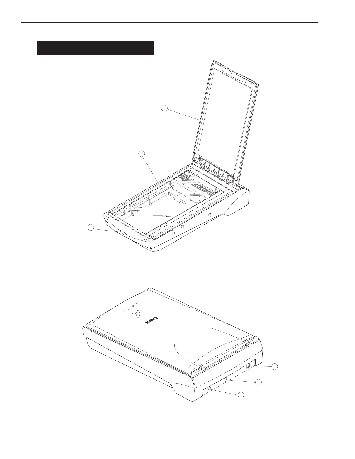
q DocumentCover
w Document Glass
e Start Button
q USB Connector
w Option Connector
e Power Connector
LTR
A4
LTR
B5
A4
B5
1
3
2
1
2
3
II. PARTS CONFIGURATION
A. Front View
Figure 1-1
B. Rear View
Figure 1-2

CHAPTER 1
1 - 3
COPYRIGHT © 2000 CANON INC. CANOSCAN FB1210U REV.0 APR. 2000 PRINTED IN JAPAN (IMPRIME AU JAPON)
III. SETTING UP THE SCANNER
A. Precautions
* Keep the scanner out of direct sunlight. Direct exposure to the sun or excessive heat may
cause damage to the scanner.
* Do not install the scanner in a humid or dusty environment.
* Use the supplied AC adapter only.
* Place the scanner securely on an even, flat surface. Tilted or uneven surface may cause a
mechanical problem.
* Keep the outer carton and packing material in case you may ship the scanner in the future.
CHAPTER 1
1 - 4
COPYRIGHT © 2000 CANON INC. CANOSCAN FB1210U REV.0 APR. 2000 PRINTED IN JAPAN (IMPRIME AU JAPON)
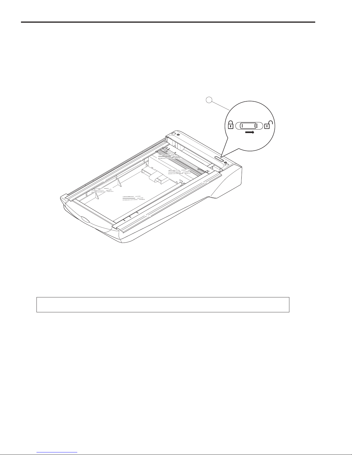
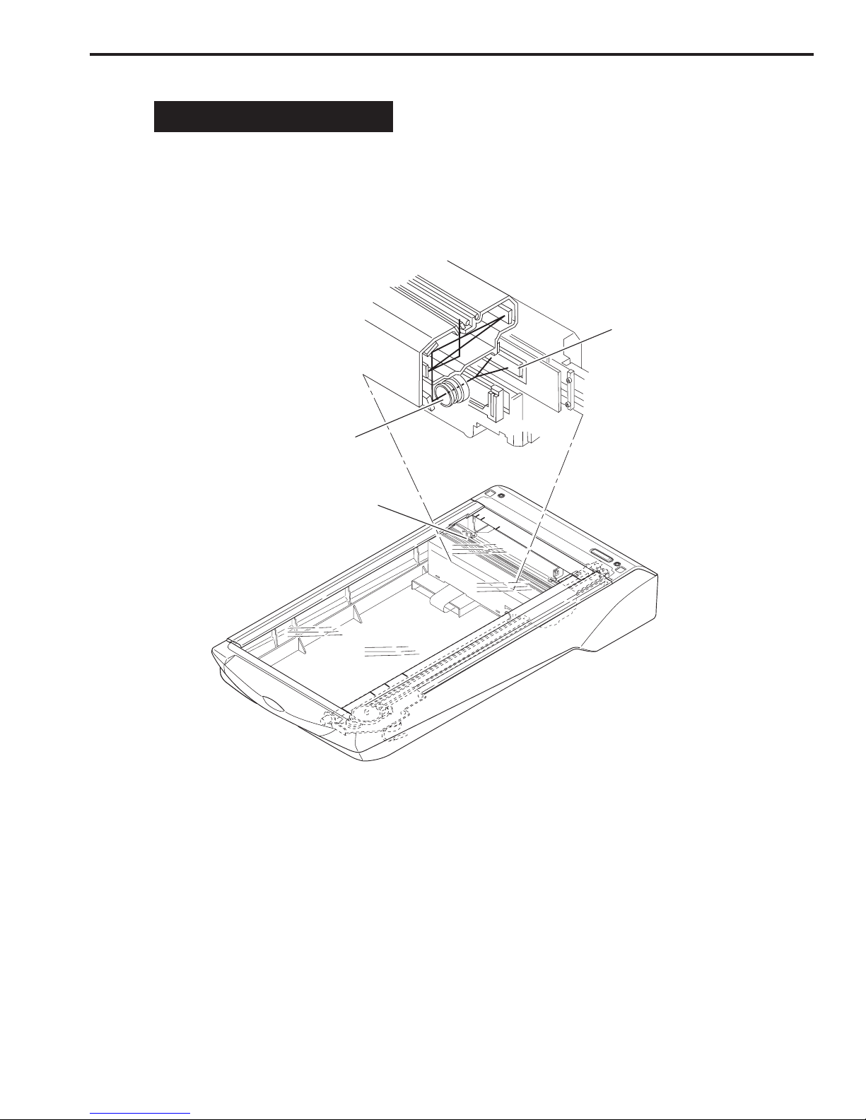
q Carriage Lock
LTR
A4
LTR
B5
A4
B5
1
B. Unlocking the Scanning Unit
Scanning unit is locked by the carriage lock to prevent a damage during transport. Unlock
the scanning unit by pushing the carriage lock toward the “unlock” mark to use the scanner.
Figure 1-3
Note : Ensure to lock the scanning unit during transport.
CHAPTER 1
1 - 5
COPYRIGHT © 2000 CANON INC. CANOSCAN FB1210U REV.0 APR. 2000 PRINTED IN JAPAN (IMPRIME AU JAPON)
1
2
4
3
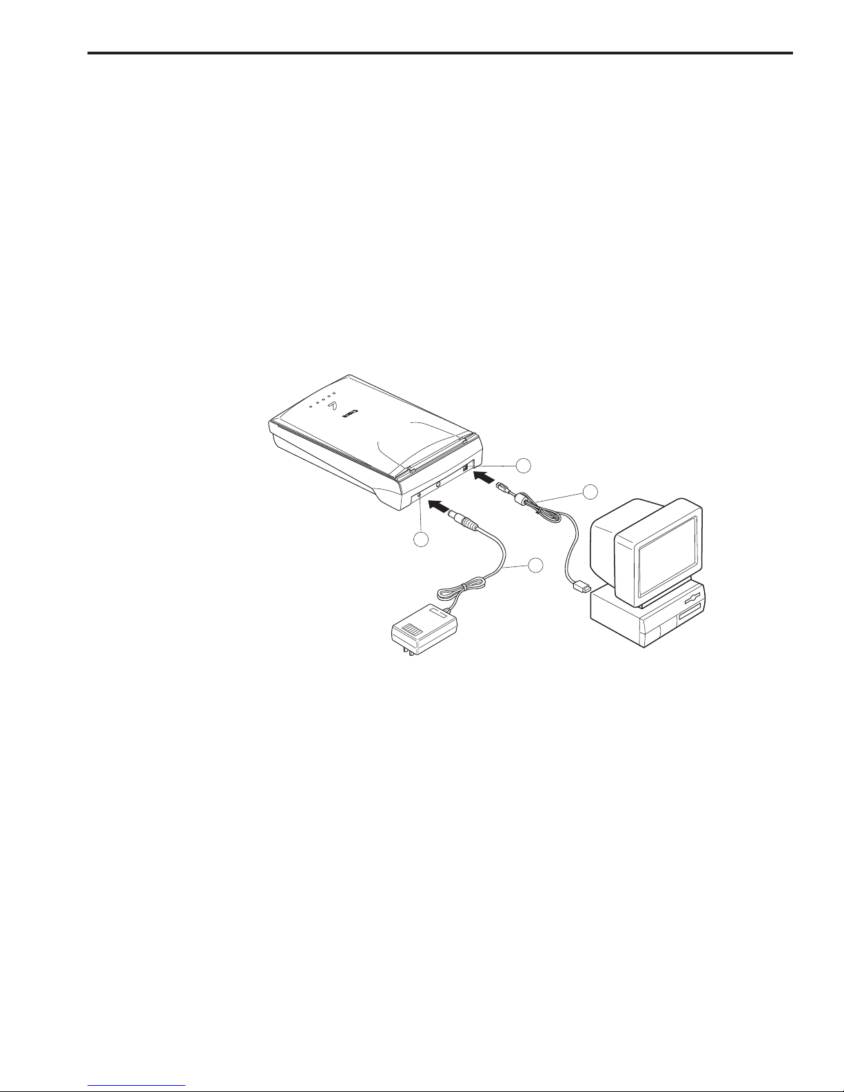
q USB Connector
w USB Cable
e Power Connector
r AC Adapter
C. Connecting the Cables
FB1210U is connected to the USB port on the host computer. Refer to the “Getting Started”
bundled with the product for details. For connecting the host computer’s cables, refer to the
manuals for the host computer.
1. Connect the AC Adapter Cable and USB Cable
1) Connect the AC adapter plug to the power connector on the scanner.
2) Connect the square plug (B type) of the USB cable to the USB connector on the scanner, and
connect the flat plug (A type) of the USB cable to the USB port on the host computer.
Figure 1-4
CHAPTER 1
1 - 6
COPYRIGHT © 2000 CANON INC. CANOSCAN FB1210U REV.0 APR. 2000 PRINTED IN JAPAN (IMPRIME AU JAPON)
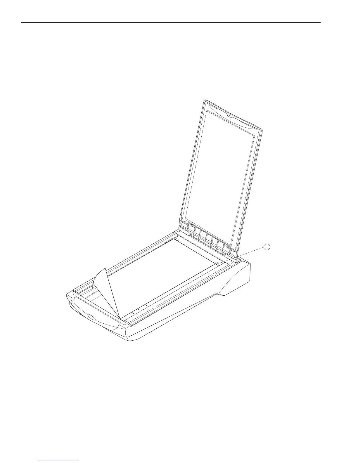
q Alignment Mark
LTR
A4
LTR
B5
A4
B5
...XYZ
1
D. Scanning a Document
1) Open the document cover.
2) Place a document on the document glass, facing the image side down and aligning the upper
corner with the alignment mark.
Figure 1-5
3) Close the document cover, caring not to dislodge the document.
4) Send “SCAN” command from the host computer to scan.

CHAPTER 1
1 - 7
COPYRIGHT © 2000 CANON INC. CANOSCAN FB1210U REV.0 APR. 2000 PRINTED IN JAPAN (IMPRIME AU JAPON)
IV. CUSTOMER’S DAILY MAINTENANCE
Dirt on the document glass may cause an unclear image or lines on an image. Clean the
document glass using the following procedures.
1) Disconnect all cables from the scanner.
2) Wipe a dirt off the document glass with a soft clean cloth dampened with water and well
wrung.
3) Thoroughly wipe water off the document glass with a dry cloth.


COPYRIGHT © 2000 CANON INC. CANOSCAN FB1210U REV.0 APR. 2000 PRINTED IN JAPAN (IMPRIME AU JAPON)
CHAPTER 2
OPERATION AND TIMING
I. BASIC OPERATION .................... 2-1
A. Functions ............................ 2-1
B. Electrical System ................ 2-2
C. Main PCB Input and Output. 2-4
D. Basic Sequences of Operations
........................................... 2-5
II. OPTICAL SYSTEM ..................... 2-7
A. Scanning Lamp .................... 2-8
B. Motor Control ..................... 2-9
III. IMAGE PROCESSING ............... 2-10
A. Outline .............................. 2-10
B. Image Processing............... 2-11
C. Calibration ........................ 2-13
D. Filter Processing ............... 2-14
E. Interpolation Processing.... 2-15
F. Averaging .......................... 2-16
G. Binary Processing .............. 2-17
H. Image Inversion
(negative/positive) ............ 2-18
IV. CONTROL SYSTEM ............ 2-19
A. Control System Diagram.... 2-19
B. Main PCB .......................... 2-19
V. INTERFACE ............................. 2-20
A. Overview of the USB Standard
......................................... 2-20
B. Benefits of the USB Scanner
......................................... 2-20
C. Signal Definitions .............. 2-21
D. Interface Connection ......... 2-21
VI. POWER SUPPLY....................... 2-22

CHAPTER 2
2 - 1
COPYRIGHT © 2000 CANON INC. CANOSCAN FB1210U REV.0 APR. 2000 PRINTED IN JAPAN (IMPRIME AU JAPON)
*
Host
Computer
Optional Film Adapter Unit FAU S-11
Scanning
Lamp
Lens
Scanning
Unit
Optical System
Drive
Motor
Image Processing System
Control
System
CCD
BGR
B
G
R
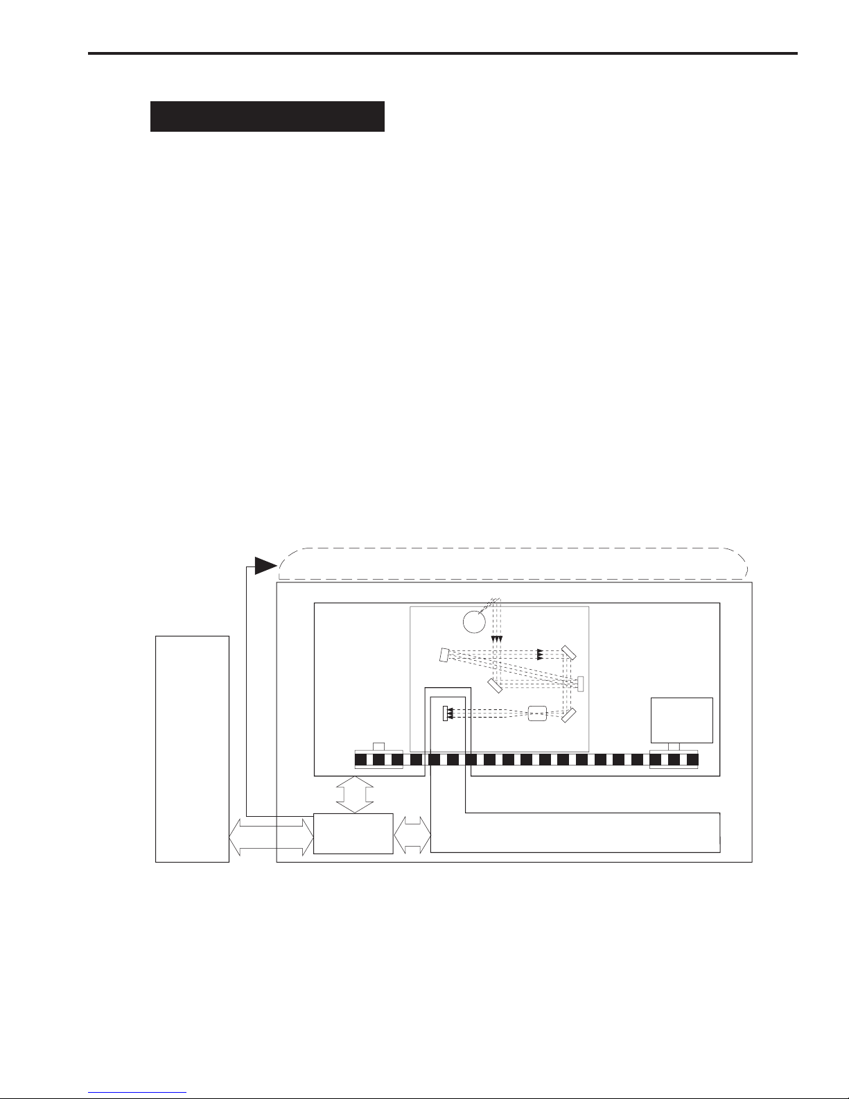
I. BASIC OPERATION
A. Functions
The scanner functions are divided into the following three main systems.
1. Optical System
The optical system consists of the scanning lamp, lens and mirrors. It exposes a document,
then the reflected light from the document is collected onto a light-sensitive device CCD
(charge-coupled device ) via the lens and mirrors.
2. Image Processing System
The image processing system consists mainly of the CCD, analog IC, and ASIC. It converts
analog signals from the CCD into digital signals, which is read by the host computer.
3. Control System
The control system consists mainly of ASIC, USB controller, CPU, and motor driver. The CPU
controls the whole scanning operation. The USB controller controls the interface between the
CPU and ASIC, while the CPU interprets all commands from the host computer.
Figure 2-1
CHAPTER 2
2 - 2
COPYRIGHT © 2000 CANON INC. CANOSCAN FB1210U REV.0 APR. 2000 PRINTED IN JAPAN (IMPRIME AU JAPON)
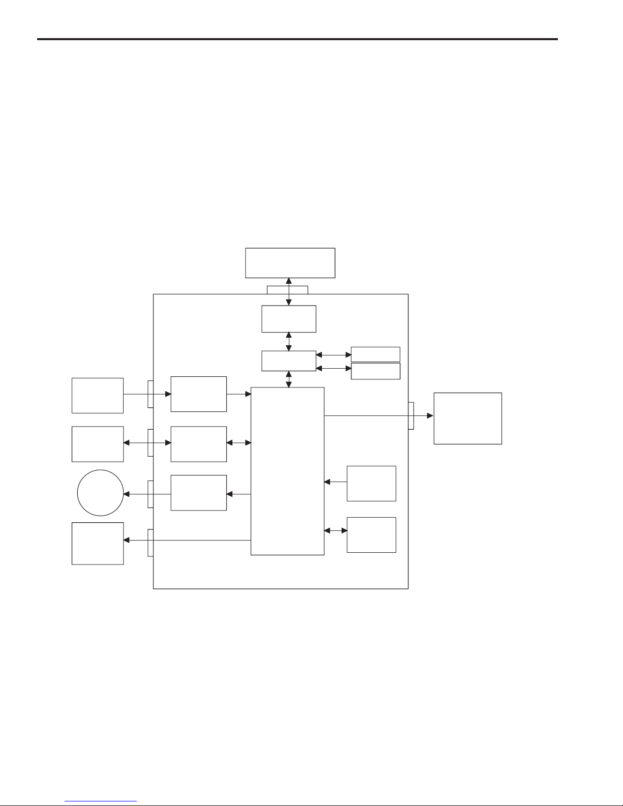
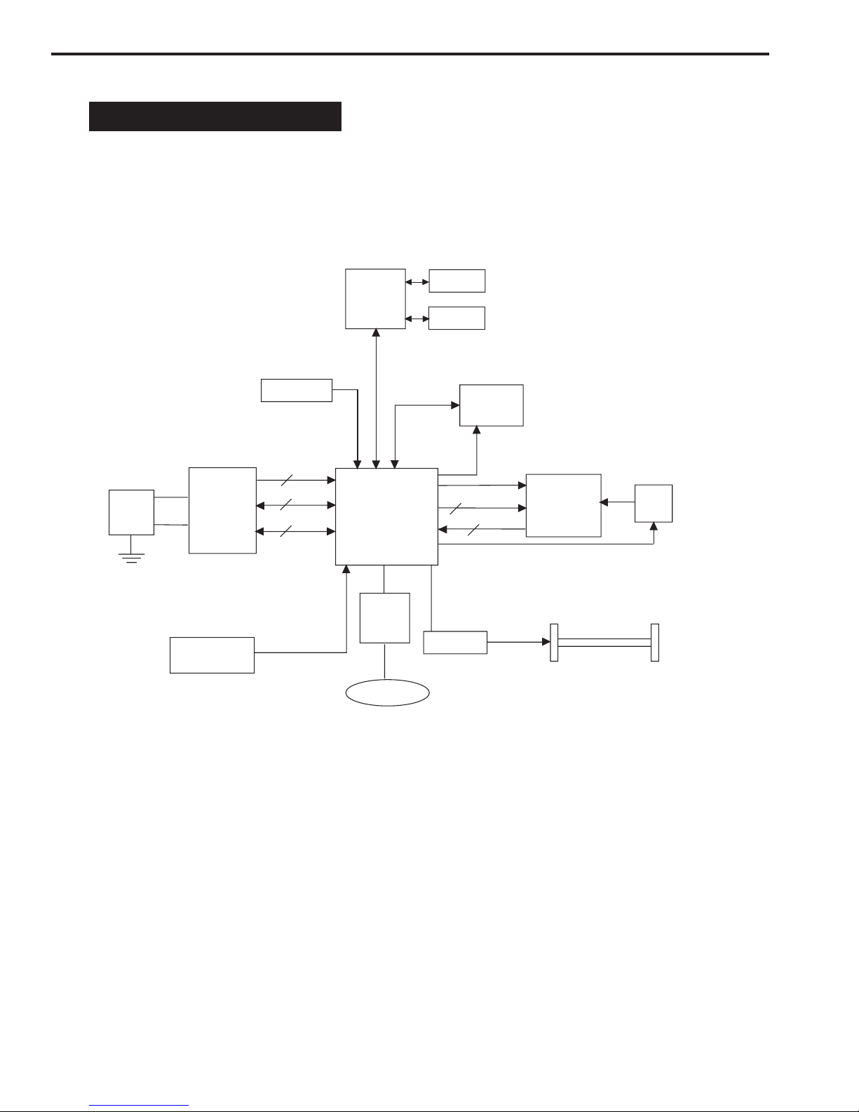
ASIC
CPU
SRAM
5V
ROM
DRAM
Motor
Driver
Analog IC
Home
Position
Sensor
Regulator
Button PCB
Start Button
Power LED
USB
Controller
Host Computer
USB Interface
+12V
AC Adapter
CCD PCB
Drive
Motor
Inverter
PCB
B. Electrical System
1. Outline
The scanner is equipped with CPU and USB controller. Host computer sends a command to
the ASIC via the USB controller and CPU, the CPU controls the whole electrical circuits and
image processing of the scanner. The image signals read by the CCD are converted into digital
data by analog IC. The digital data are then processed by the ASIC and output to the host
computer via USB interface.
Figure 2-2

CHAPTER 2
2 - 3
COPYRIGHT © 2000 CANON INC. CANOSCAN FB1210U REV.0 APR. 2000 PRINTED IN JAPAN (IMPRIME AU JAPON)
2. Functions of the Main PCB
1) Analog IC
Converts the image signals (analog signals) read by the CCD into digital data.
- CDS (Correlated Double Sampling)
- AGC (Auto Gain Control)
- 14-bit A/D converter (Analog-to-Digital Converter)
2) ASIC
Performs various processing:
- DRAM control
- CCD timing clock creation
- Line buffer control
- CCD output line difference adjustment
- Image processing (Binary processing, Image inversion)
- Shading correction
- Motor driver control
3) DRAM
Stores the shading correction data when performing shading correction, and the image data
when scanning.
4) Motor Driver
A monolithic microstep motor driver supplies power to the drive motor.
5) USB Controller
Transmits data between the host computer and ASIC.
6) CPU
Interprets commands from the host computer to generate parameter for the ASIC to perform
various processing.
CHAPTER 2
2 - 4
COPYRIGHT © 2000 CANON INC. CANOSCAN FB1210U REV.0 APR. 2000 PRINTED IN JAPAN (IMPRIME AU JAPON)
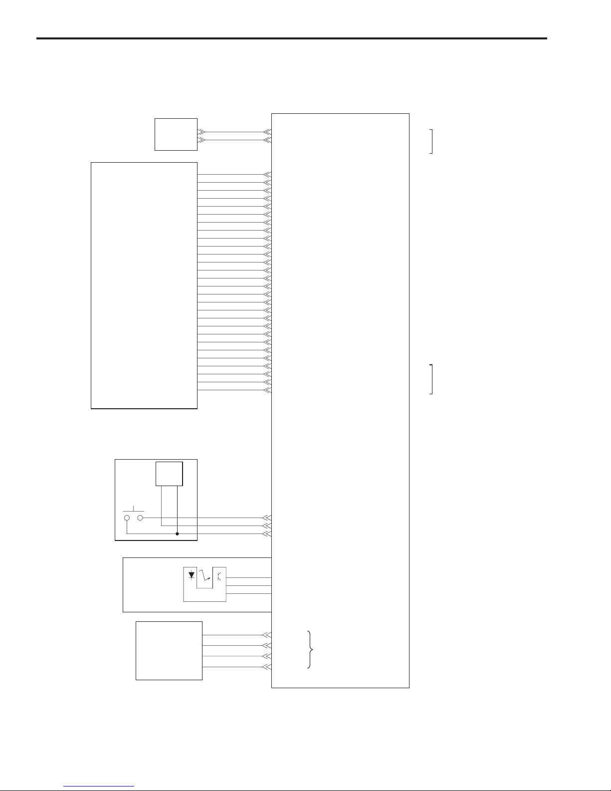
JP5-1
-2
-3
-4
Drive Motor
JP3-1
-2
-3
VCC
LED
HOTKEY0
+12V
GND
Vbus
D-
D+
GND
JP2-1
-2
-3
CHK_FAU
FAU_LAMP
GND
JP1-1
-2
-3
-4
-5
-6
-7
-8
-9
-10
-11
-12
-13
-14
-15
-16
-17
-18
-19
-20
-21
-22
-23
-24
-25
-26
-27
-28
LAMP_GND
LAMP_GND
12V_LAMP
12V_LAMP
+15VP
+15VP
DGND
PHI1
DGND
PHI2
DGND
CLB
DGND
DGND
DGND
RB
DGND
TG
VCC
DGND
AGND
AGND
AGND
CCD_B
AGND
CCD_G
AGND
CCD_R
OUT1B
OUT1A
OUT2A
OUT2B
JP4-1
-2
-3
-4
To Host
Computer
J1-1
-2
Home Position
Sensor
Button PCB
Drive motor drive signal
Start
Button
Power
LED
"H" when scanning unit
is in home position
"H" when power LED
is ON
"H" when start button
is pressed
To FAU
Main PCB
AC
Adapter
Scanning Unit
C. Main PCB Input and Output
Figure 2-3
CHAPTER 2
2 - 5
COPYRIGHT © 2000 CANON INC. CANOSCAN FB1210U REV.0 APR. 2000 PRINTED IN JAPAN (IMPRIME AU JAPON)
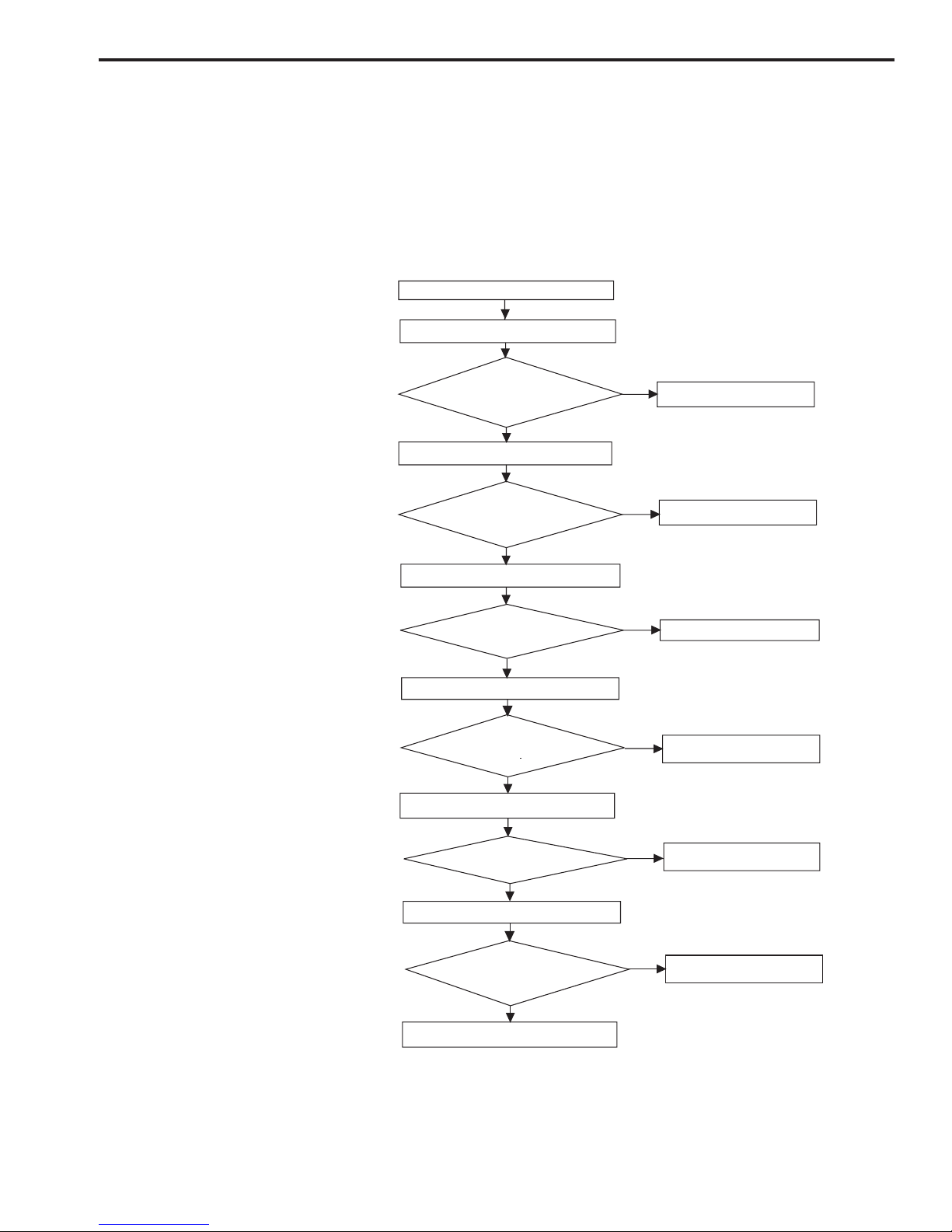
Execute R/W test (2)
N
Y
N
Y
N
Y
Y
N
Y
N
Connect the scanner.
Power LED is ON?
N
Y
Power ON
Execute USB cable test (1)
(1) Check Analog IC register
and ASIC port
Error returns
(2) Execute Analog IC
read/write test
(3) Access a fixed address
(4) Access full memory
Analog IC R/W test failed?
Error returns
Error returns
Error returns
Error returns
Execute memory R/W test (3)
Memory R/W test failed ?
Execute full memory R/W test (4)
Full memory R/W test failed ?
Error returns
Execute DMA transit test (5)(5) Access DMA transit test
DMA transit test failed ?
Check carriage lock on/off (6)
Carriage lock is off ?
Standby
(6) Move drive motor forward
100 steps then backward
to check carriage lock on/off
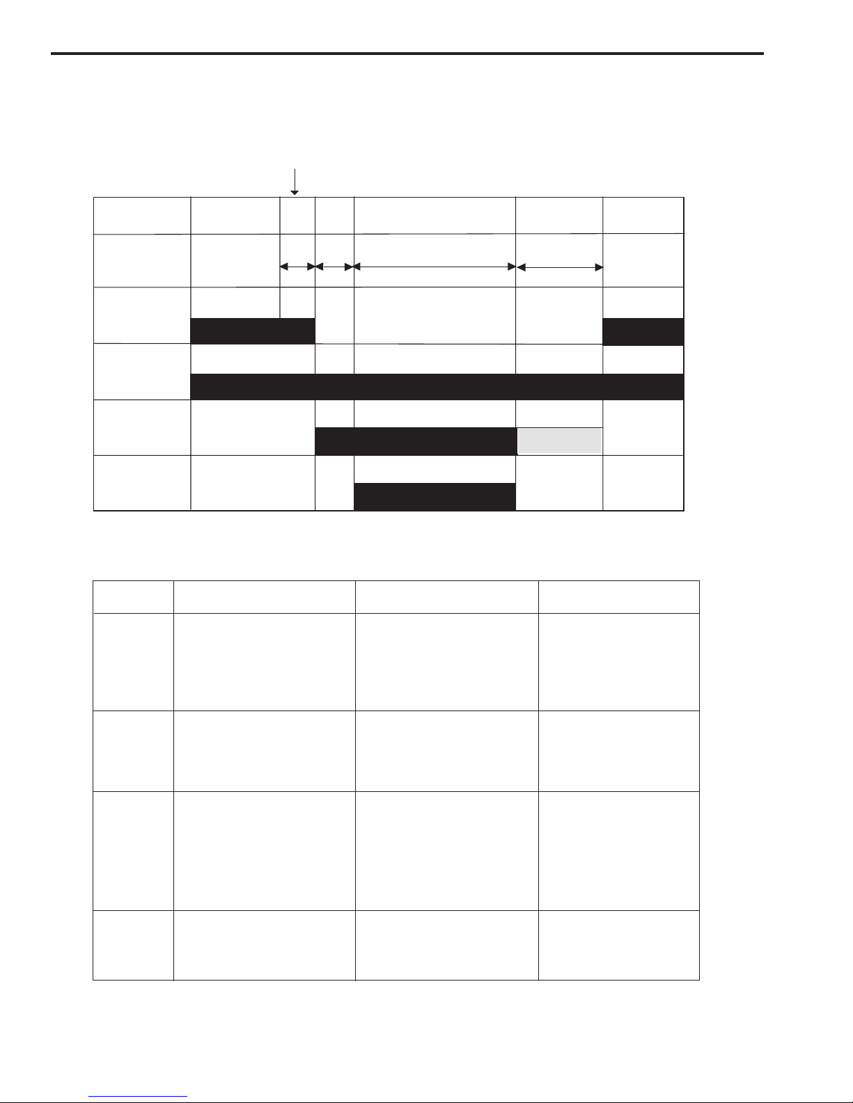
D. Basic Sequences of Operations
The basic sequences of operations of CanoScan FB1210U is divided into the power ON
sequence and the document scanning sequence.
1. Power ON Sequence
Figure 2-4
CHAPTER 2
2 - 6
COPYRIGHT © 2000 CANON INC. CANOSCAN FB1210U REV.0 APR. 2000 PRINTED IN JAPAN (IMPRIME AU JAPON)
0.1
2.0 90.0
9.0
Home Position
Sensor
Sequence
Time (Sec.)
Scanning Lamp
ON Signal
Drive Motor
Interface Signal
Scan Command
Standby Setup Scanning Unit Forward
Scanning Unit
Backward
Standby
Sequence
Purpose
Remarks
Operation
Standby
Setup
Scanning unit
forward
After the power ON sequence is
completed until the scanner
receives a scan command from
the host computer
Scanning unit
backward
To maintain the scanner ready
for scan
From the scanner receives a
scan command until it starts
scanning
To execute calibration for setting
gain data and shading data
The data is stored in DRAM
After the scanner starts scanning
until whole scan area specified
by the host computer are
scanned
After the scanning unit starts
moving backward until it returns
to the home position
To execute image processing
according to the command from
the host computer and send
image data to the host computer
while scanning
To return the scanning unit to the
home position to ready for the
next scan
Home position is detected
by the home position sensor
2. Document Scanning Sequence
Figure 2-5
Table 2-1
CHAPTER 2
2 - 7
COPYRIGHT © 2000 CANON INC. CANOSCAN FB1210U REV.0 APR. 2000 PRINTED IN JAPAN (IMPRIME AU JAPON)
LTR
A4
LTR
B5
A4
B5
CCD
Lens
Scanning Lamp
II. OPTICAL SYSTEM
The optical system has functions from exposing a document by the scanning lamp to
collecting the reflected light to the CCD. The system employs a 3-line CCD to recognize colors
of the document.
Figure 2-6

CHAPTER 2
2 - 8
COPYRIGHT © 2000 CANON INC. CANOSCAN FB1210U REV.0 APR. 2000 PRINTED IN JAPAN (IMPRIME AU JAPON)
Host
Computer
ASIC
PWM
GND
CCD
PCB
GND
AC
Adapter
Main PCB
Inverter
PCB
Scanning Lamp
CPU
A. Scanning Lamp
When the scanner is powered on, the scanning lamp lights to standby. The scanner is
provided with an energy saving setting which is made in the Scanner Utilities Dialog. For
example, if it is set for 30 minutes, then no scan command is sent for 30 minutes, ASIC sends
the scanning lamp off signal to turn off the lamp.
Figure 2-7
CHAPTER 2
2 - 9
COPYRIGHT © 2000 CANON INC. CANOSCAN FB1210U REV.0 APR. 2000 PRINTED IN JAPAN (IMPRIME AU JAPON)
Host
Computer
ASIC
PA+
PA-
PB+
PB-
Motor
Driver
Main PCB
Drive
Motor
OUT1B
OUT1A
OUT2A
OUT2B
B. Motor Control
When the host computer sends a command to change scaling/resolution, the motor driver
current control signals [PA+, PA-, PB+, PB-] are changed to generate a torque for the rotating
speed. Yet, the reverse speed of the scanning unit is always constant.
The ASIC receives each command sent from the host computer via the USB interface to
control the motor by four-phase motor driver pulse signals [OUT1B, OUT1A, OUT2A, OUT2B].
Figure 2-8
CHAPTER 2
2 - 10
COPYRIGHT © 2000 CANON INC. CANOSCAN FB1210U REV.0 APR. 2000 PRINTED IN JAPAN (IMPRIME AU JAPON)
CPU
SRAM
ROM
Clock
DRAM
Data
Control
Signal
Clock
Control Signal
Data
USB Connector
USB
USB
Controller
Control Signal
Data
Status Signal
Home Position
Sensor
ASIC
Motor
Driver
Inverter
Analog IC
Vin
CCD
Control Clock
D+
D-
Drive Motor
Scanning Lamp
III. IMAGE PROCESSING
A. Outline
The image processing system converts light signals read by the CCD to electric signals, then
outputs the image data to the host computer via the USB interface upon various image
processing.
Figure 2-9
CHAPTER 2
2 - 11
COPYRIGHT © 2000 CANON INC. CANOSCAN FB1210U REV.0 APR. 2000 PRINTED IN JAPAN (IMPRIME AU JAPON)
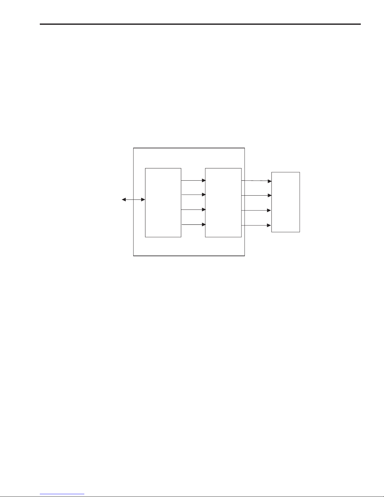
CCD
R
G
B
Analog
Amplifier
D/A Converter
A/D Converter
Digital data
To ASIC
Analog IC
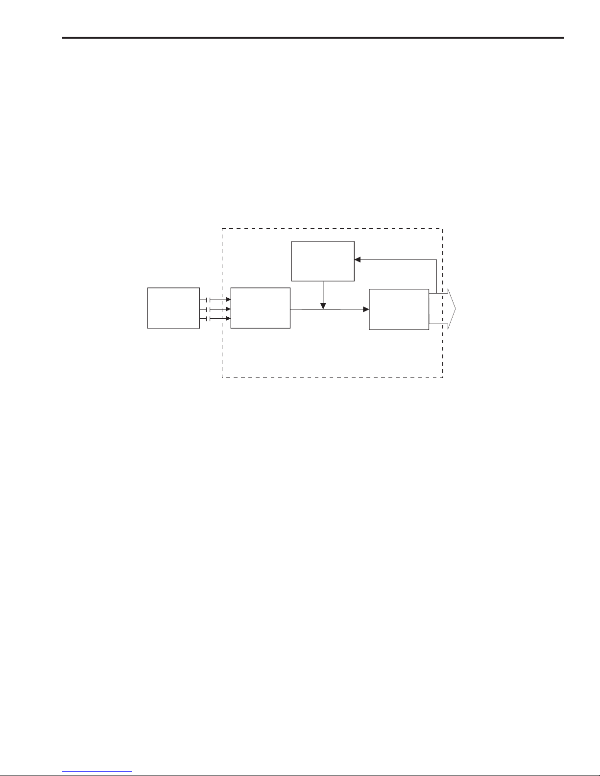
B. Image Processing
1. Analog IC
Output signal from the CCD is an analog signal which cannot be used as image data. So
RGB output signal from the CCD is amplified by analog amplifier to generate analog data. The
generated data is converted into averaged analog signal by D/A converter, then got feedback to
the A/D converter to output constant digital data to the ASIC.
Figure 2-10
 Loading...