

Canon CANOSCAN D1230 series, CANOSCAN D2400 series, CanoScan D1230U, CanoScan D1230UF, CanoScan D2400U Service Manual
...
COPYRIGHT © 2001 CANON INC. CANOSCAN D1230U/D2400U REV.0 MARCH 2001 PRINTED IN JAPAN (IMPRIME AU JAPON)
MARCH 2001
JY8-1319-000
REVISION 0
SERVICE
MANUAL
SERIES

COPYRIGHT © 2001 CANON INC. CANOSCAN D1230U/D2400U REV.0 MARCH 2001 PRINTED IN JAPAN (IMPRIME AU JAPON)
COPYRIGHT © 2001 CANON INC.
Printed in Japan
Imprimè au Japon
Use of this manual should be strictly supervised
to avoid disclosure of confidential information.

COPYRIGHT © 2001 CANON INC. CANOSCAN D1230U/D2400U REV.0 MARCH 2001 PRINTED IN JAPAN (IMPRIME AU JAPON)
CanoScan D1230U 6683A001AA AZQ000000-
6683A003AA DZQ0000006683A004AA EZQ0000006683A005AA FZQ0000006683A006AA LZQ0000006683A007AA JZQ000000-
CanoScan D1230UF 6684A002AA CZR000000-
6684A003AA DZR0000006684A004AA EZR0000006684A008AA MZR0000006684A009AA KZR0000006684A010AA LZR000000-
FAU-S12 6687A001AA AZS000000-
6687A002AA BZS000000-
CanoScan D2400U 6785A001AA AZT000000-
6685A002AA DZT0000006685A003AA EZT000000-
CanoScan D2400UF 6685A001AA AZU000000-
6685A002AA CZU0000006685A003AA DZU0000006685A004AA EZU0000006685A005AA FZU0000006685A006AA LZU0000006685A007AA JZU0000006685A008AA MZU000000-
FAU-S13 6774A001AA AZV000000-
6774A002AA BZV000000-
Serial Number List

COPYRIGHT © 2001 CANON INC. CANOSCAN D1230U/D2400U REV.0 MARCH 2001 PRINTED IN JAPAN (IMPRIME AU JAPON)
CONTENTS
I. SPECIFICATIONS ...........................1-1
II. PARTS CONFIGURATION ............... 1-5
A. Front View ...............................1-5
B. Rear View .................................1-5
C. FAU Front View ....................... 1-6
D. FAU Rear View......................... 1-6
CHAPTER 2 : OPERATION AND TIMING
CHAPTER 1 : GENERAL DESCRIPTIONS
I. BASIC OPERATION ........................2-1
A. Functions .................................2-1
B. Electrical System .....................2-2
C. Main PCB Input and Output ...2-4
D. Document Scanning
Sequence ................................. 2-6
II. OPTICAL SYSTEM .......................... 2-7
A. Outline ..................................... 2-7
B. Lamp Lighting Circuit .............. 2-8
C. FARE (Film Automatic Retouch-
ing and Enhancement) .......... 2-10
D. Motor Control Circuit ............ 2-12
III. IMAGE PROCESSING .................... 2-13
A. Outline ................................... 2-13
B. Image Processing ................... 2-13
IV. CONTROL SYSTEM ...................... 2-20
A. Control System Diagram ........ 2-20
B. Main PCB ............................... 2-20
V. INTERFACE ................................... 2-21
A. Outline of USB Standard ........ 2-21
B. Benefits of USB Scanner ........ 2-21
C. Signal Definitions .................. 2-22
D. Interface Connection ............. 2-22
VI. POWER SUPPLY ........................... 2-23
III. SETTING UP THE SCANNER .........1-7
A. Precautions ..............................1-7
B. Unlocking the Carriage Lock ... 1-8
C. Connecting the Cables............. 1-9
D. Scanning a Document ...........1-10
E. Connecting FAU ..................... 1-11
IV. CUSTOMER’S DAILY
MAINTENANCE ....................... 1-14
CHAPTER 3 : MECHANICAL SYSTEM
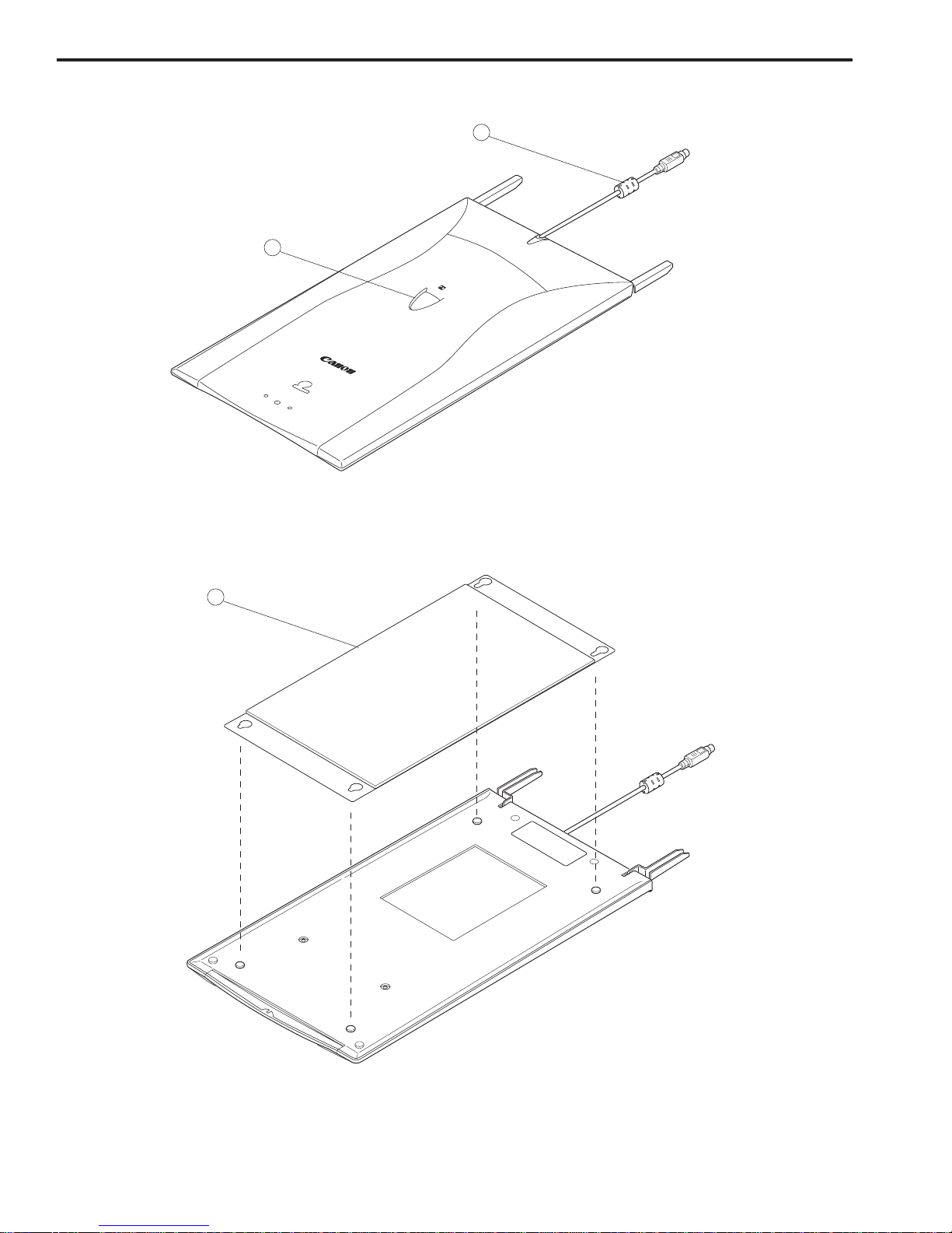
I. PARTS REPLACEMENT ..................3-1
A. Precautions .............................. 3-1
II. EXTERNALS ...................................3-2
A. Removing the Document
Cover........................................ 3-2
B. Removing the Top Cover and
Document Glass ....................... 3-3
III. PCBs ............................................... 3-4
A. Removing the Main PCB ........... 3-4
B. Removing the Button PCB ....... 3-6
IV. OPTICAL SYSTEM.......................... 3-9
A. Removing the Scanning Unit ... 3-9
B. Removing the Drive Motor ..... 3-15
C. Attaching the Drive Motor ..... 3-17

COPYRIGHT © 2001 CANON INC. CANOSCAN D1230U/D2400U REV.0 MARCH 2001 PRINTED IN JAPAN (IMPRIME AU JAPON)
I. INTRODUCTION .............................5-1
A. Initial Check ............................ 5-1
B. Others ...................................... 5-1
II. TROUBLESHOOTING
FLOWCHART .................................. 5-2
A. Power LED Failure ................... 5-2
B. Communication Failure ........... 5-3
III. PROBLEM, CAUSE AND
CORRECTIVE ACTION ................... 5-4
A. Power LED Not Lighting .......... 5-4
B. Communication Failure ........... 5-4
C. Scanning Unit Movement
Failure ...................................... 5-5
D. Poor Image Quality ................... 5-5
E. Acoustic Noise ......................... 5-5
IV. CANON SCANNER TEST .................. 5-6
A. Outline ..................................... 5-6
B. Operating Environment ........... 5-6
C. Functions ................................ 5-7
D. Functions Descriptions ........... 5-8
E. Error Message ........................ 5-16
CHAPTER 5 : TROUBLESHOOTING
CHAPTER 4 : MAINTENANCE AND SERVICING
I. PERIODICAL REPLACEMENT
PARTS ............................................ 4-1
II. CONSUMABLE PARTS
DURABILITY ................................... 4-1
III. PERIODICAL SERVICING ..............4-1
IV. SPECIAL TOOLS ............................ 4-1
V. SOLVENTS AND LUBRICANTS ......4-1
CHAPTER 6 : PARTS CATALOG
FIGURE 001 ................................... 6-2
FIGURE 100 ................................... 6-4
FIGURE 200 ................................... 6-6
FIGURE 300 ................................... 6-8
APPENDIX
I. GENERAL CIRCUIT DIAGRAM
(CanoScan D1230U)...................... A-1
II. GENERAL CIRCUIT DIAGRAM
(CanoScan D2400U)...................... A-2
III. MAIN PCB CIRCUIT DIAGRAM
(CanoScan D1230U)...................... A-3
IV. MAIN PCB CIRCUIT DIAGRAM
(CanoScan D2400U).................... A-10

COPYRIGHT © 2001 CANON INC. CANOSCAN D1230U/D2400U REV.0 MARCH 2001 PRINTED IN JAPAN (IMPRIME AU JAPON)
CHAPTER 1
GENERAL DESCRIPTIONS
I. SPECIFICATIONS ........................... 1-1
II. PARTS CONFIGURATION ............... 1-5
A. Front View ...............................1-5
B. Rear View .................................1-5
C. FAU Front View ....................... 1-6
D. FAU Rear View......................... 1-6
III. SETTING UP THE SCANNER .........1-7
A. Precautions ..............................1-7
B. Unlocking the Carriage Lock ... 1-8
C. Connecting the Cables............. 1-9
D. Scanning a Document ...........1-10
E. Connecting FAU ..................... 1-11
IV. CUSTOMER’S DAILY
MAINTENANCE ............................. 1-14


CHAPTER 1
1 - 1
COPYRIGHT © 2001 CANON INC. CANOSCAN D1230U/D2400U REV.0 MARCH 2001 PRINTED IN JAPAN (IMPRIME AU JAPON)
I. SPECIFICATIONS
CanoScan D1230U
Scanner Main Unit
Type : Flatbed image scanner
Scanning Part
Image sensor : 10,550-pixel 3-line CCD
Light source : Cold cathode fluorescent lamp
Document type : Sheet, Book
Document alignment position : Right-end corner
Max. document size : A4/Letter size (216 x 297mm)
Image output mode : Color14-bit for RGB each (16-bit input)
Grayscale (256 gradations)
Binary (black and white)
Optical resolution : 1200 dpi x 2400 dpi
Scanning time : 3.60ms/line (600 dpi or lower)
7.20ms/line (601 dpi or higher)
Cropping of scan area : One rectangular area only
FAU-S12 Scanning Part
Film type : Color and monochrome, negative and positive
Film size : 35mm sleeve (preview : 3 frames, scan : 1 frame)
35mm slide mount
Brownie (Max. 120x60mm)
4x5 inches
Light source : Cold cathode fluorescent lamp
Power source : Supplied from CanoScan D1230U
Scanning time : 3.38 to 101.2ms/line (automatically selected depending on
films)
Cropping of scan area : One rectangular area only
Interface Part
Interface : USB connector (Universal Serial Bus 1.1)
FAU connector (8-pin)
Power connector (for AC adapter)
Operating Part
Start button : 1 each on D1230U and FAU-S12

CHAPTER 1
1 - 2
COPYRIGHT © 2001 CANON INC. CANOSCAN D1230U/D2400U MARCH 2001 PRINTED IN JAPAN (IMPRIME AU JAPON)
Others
Operating environment : Temperature : 10 to 35 degrees
Relative humidity : 10 to 90%RH
Air pressure : 613 to 1013 hPa
(When using FAU) : Temperature : 10 to 35 degrees
Relative humidity : 10 to 85%RH
Air pressure : 613 to 1013 hPa
Power source : 100V to 120V
220V to 240V
Power consumption : 17W max. (during operation)
8W (during standby)
(When using FAU) : 20W max. (during operation)
8W (during standby)
Dimensions (Scanner) : 286.0 (Width) x 461.0 (Depth) x 92.5 (Height) mm
(FAU) : 285.0 (Width) x 410.0 (Depth) x 31.0 (Height) mm
Weight (Scanner) : 3.4kg
(FAU) : 1.1kg

CHAPTER 1
1 - 3
COPYRIGHT © 2001 CANON INC. CANOSCAN D1230U/D2400U REV.0 MARCH 2001 PRINTED IN JAPAN (IMPRIME AU JAPON)
CanoScan D2400U
Scanner Main Unit
Type : Flatbed image scanner
Scanning Part
Image sensor : 10,680-pixel 6-line CCD
Light source : Cold cathode fluorescent lamp
Document type : Sheet, Book
Document alignment position : Right-end corner
Max. document size : A4/Letter size (216 x 297mm)
Image output mode : Color16-bit for RGB each
Grayscale (256 gradations)
Binary (black and white)
Optical resolution : 2400 dpi x 4800 dpi
Scanning time : 4.5ms/line (600 dpi or lower)
9.0ms/line (601 dpi or higher)
Cropping of scan area : One rectangular area only
FAU-S13 Scanning Part
Film type : Color and monochrome, negative and positive
Film size : 35mm sleeve (preview : 3 frames, scan : 1 frame)
35mm slide mount
Brownie (Max. 120x60mm)
4x5 inches
Light source : Cold cathode fluorescent lamp
Power source : Supplied from CanoScan D2400U
Scanning time : 4.5 to 162.0ms/line (automatically selected depending on
films)
Cropping of scan area : One rectangular area only
Interface Part
Interface : USB connector (Universal Serial Bus 1.1)
FAU connector (8-pin)
Power connector (for AC adapter)
Operating Part
Start button : 1 each on D2400U and FAU-S13

CHAPTER 1
1 - 4
COPYRIGHT © 2001 CANON INC. CANOSCAN D1230U/D2400U MARCH 2001 PRINTED IN JAPAN (IMPRIME AU JAPON)
Others
Operating environment : Temperature : 10 to 35 degrees
Relative humidity : 10 to 90%RH
Air pressure : 613 to 1013 hPa
(When using FAU) : Temperature : 10 to 35 degrees
Relative humidity : 10 to 85%RH
Air pressure : 613 to 1013 hPa
Power source : 100V to 120V
220V to 240V
Power consumption : 17W max. (during operation)
8W (during standby)
(When using FAU) : 20W max. (during operation)
8W (during standby)
Dimensions (Scanner) : 286.0 (Width) x 461.0 (Depth) x 92.5 (Height) mm
(FAU) : 285.0 (Width) x 410.0 (Depth) x 31.0 (Height) mm
Weight (Scanner) : 3.4kg
(FAU) : 1.1kg
Specifications are subject to change without prior notice.

CHAPTER 1
1 - 5
COPYRIGHT © 2001 CANON INC. CANOSCAN D1230U/D2400U REV.0 MARCH 2001 PRINTED IN JAPAN (IMPRIME AU JAPON)
q Document Cover
w Document Glass
e Start Button
q USB Connector
w FAU Connector
e Power Connector
II. PARTS CONFIGURATION
A. Front View
Figure 1-1
B. Rear View
Figure 1-2
A4
LTR
B5
A4
1
3
2
LTR
B5
1
2
3
CHAPTER 1
1 - 6
COPYRIGHT © 2001 CANON INC. CANOSCAN D1230U/D2400U MARCH 2001 PRINTED IN JAPAN (IMPRIME AU JAPON)
C. FAU Front View
q FAU Cable
w Start Button
Figure 1-3
D. FAU Rear View
q Protective Cover
Figure 1-4
Film Scan
2
1
1

CHAPTER 1
1 - 7
COPYRIGHT © 2001 CANON INC. CANOSCAN D1230U/D2400U REV.0 MARCH 2001 PRINTED IN JAPAN (IMPRIME AU JAPON)
III. SETTING UP THE SCANNER
A. Precautions
* Keep the scanner out of direct sunlight. Direct exposure to the sun or excessive heat may
cause damage to the scanner.
* Do not install the scanner in a humid or dusty environment.
* Use the supplied AC adapter only.
* Place the scanner securely on an even, flat surface. Tilted or uneven surface may cause a
mechanical problem.
* Keep the outer carton and packing material in case you may ship the scanner in the future.

CHAPTER 1
1 - 8
COPYRIGHT © 2001 CANON INC. CANOSCAN D1230U/D2400U MARCH 2001 PRINTED IN JAPAN (IMPRIME AU JAPON)
q Carriage Lock
B. Unlocking the Carriage Lock
Scanning unit is locked by the carriage lock to prevent a damage during transport. Unlock
the carriage lock by pushing toward the “unlock” mark to use the scanner.
Figure 1-5
Note : Ensure to lock the carriage lock during transport.
LTR
A4
LTR
B5
A4
B5
1
CHAPTER 1
1 - 9
COPYRIGHT © 2001 CANON INC. CANOSCAN D1230U/D2400U REV.0 MARCH 2001 PRINTED IN JAPAN (IMPRIME AU JAPON)
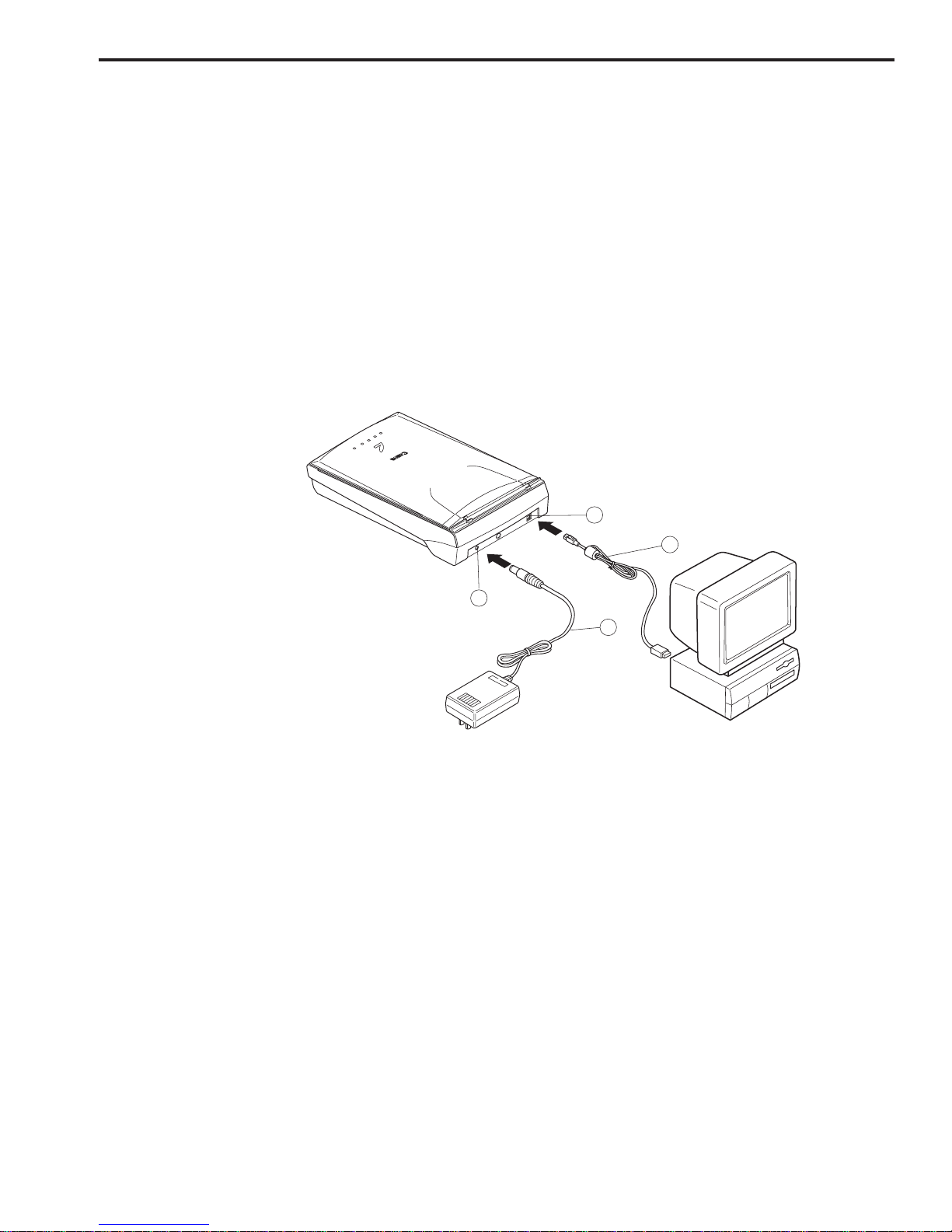
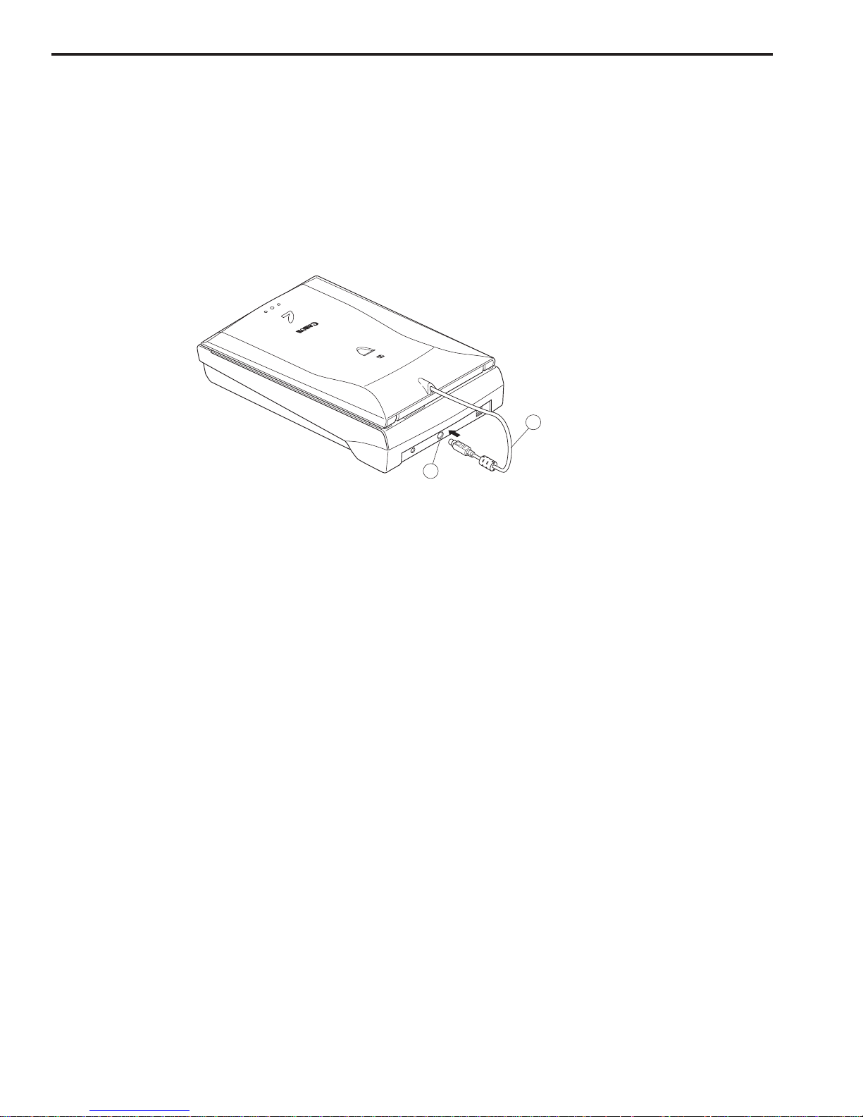
q USB Connector
w USB Cable
e Power Connector
r AC Adapter
C. Connecting the Cables
D1230U/D2400U is connected to the USB port on the host computer. Refer to the “Getting
Started” guide supplied with the product for details. For connecting the host computer’s
cables, refer to the manuals for the host computer.
1. Connecting the AC Adapter Cable and USB Cable
1) Connect the AC adapter cable to the power connector on the scanner.
2) Connect the square plug (B type) of the USB cable to the USB connector on the scanner,
and connect the flat plug (A type) of the USB cable to the USB port on the host computer.
Figure 1-6
1
2
4
3
CHAPTER 1
1 - 10
COPYRIGHT © 2001 CANON INC. CANOSCAN D1230U/D2400U MARCH 2001 PRINTED IN JAPAN (IMPRIME AU JAPON)
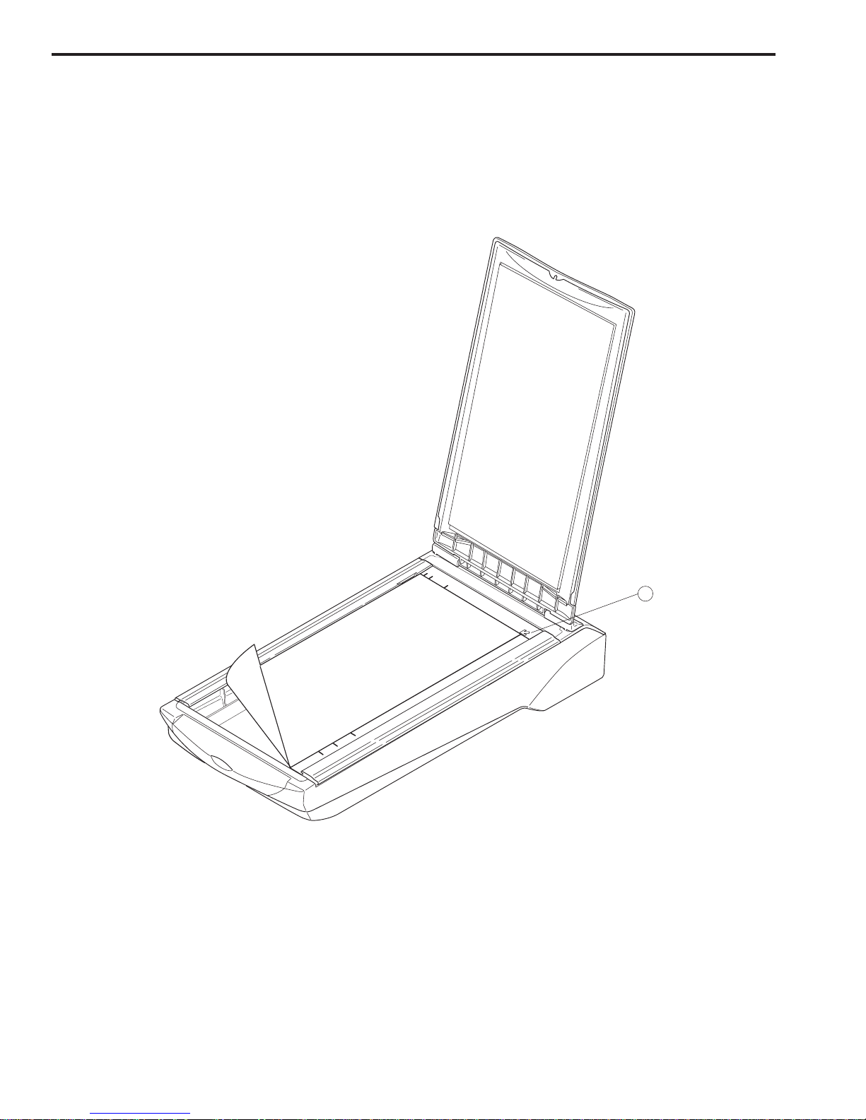
q Alignment Mark
D. Scanning a Document
1) Open the document cover.
2) Place a document on the document glass, facing the image side down and aligning the upper
corner with the alignment mark.
Figure 1-7
3) Close the document cover, caring not to dislodge the document.
4) Send “SCAN” command from the host computer to scan.
A4
LTR
B5
A4
B5
...XYZ
1
TRL
CHAPTER 1
1 - 11
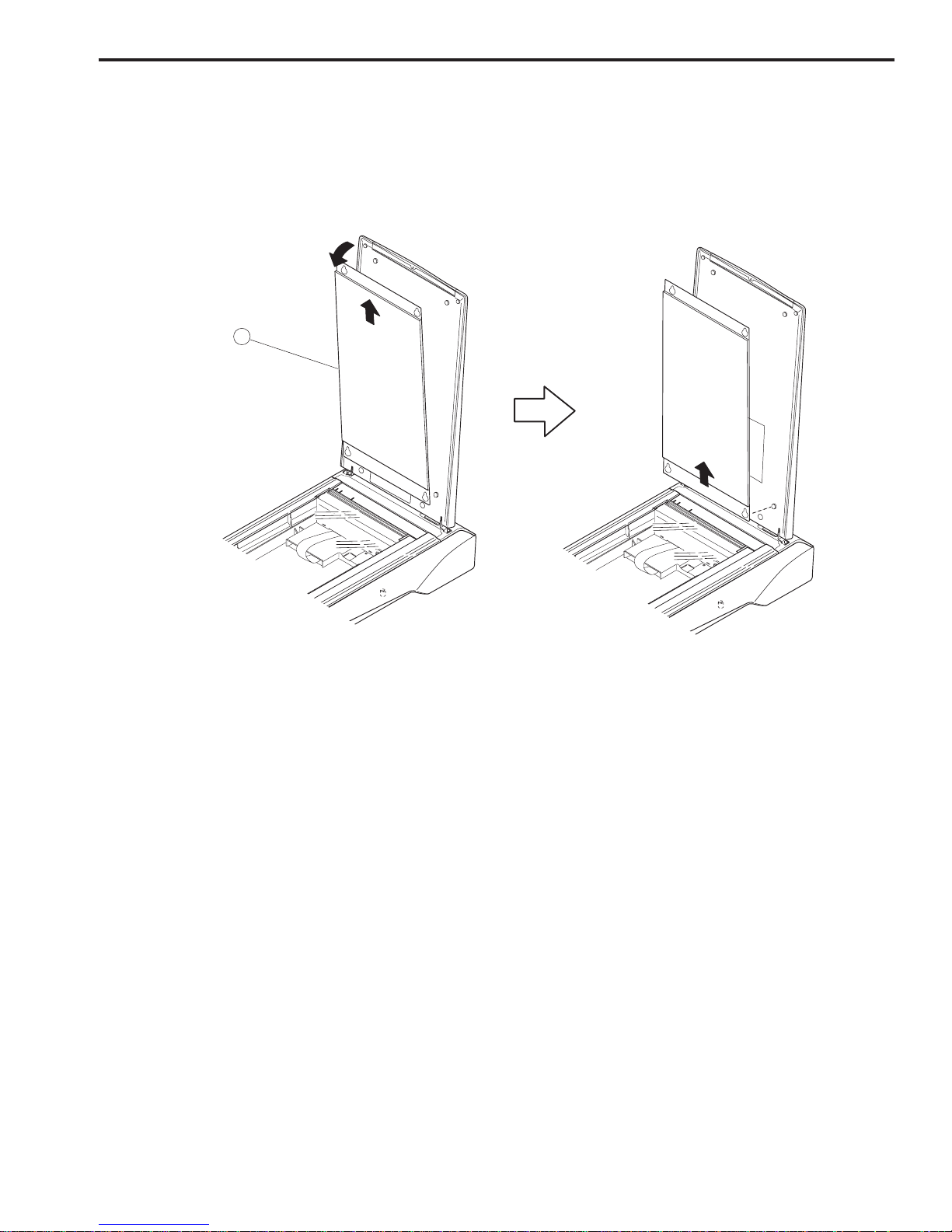
COPYRIGHT © 2001 CANON INC. CANOSCAN D1230U/D2400U REV.0 MARCH 2001 PRINTED IN JAPAN (IMPRIME AU JAPON)
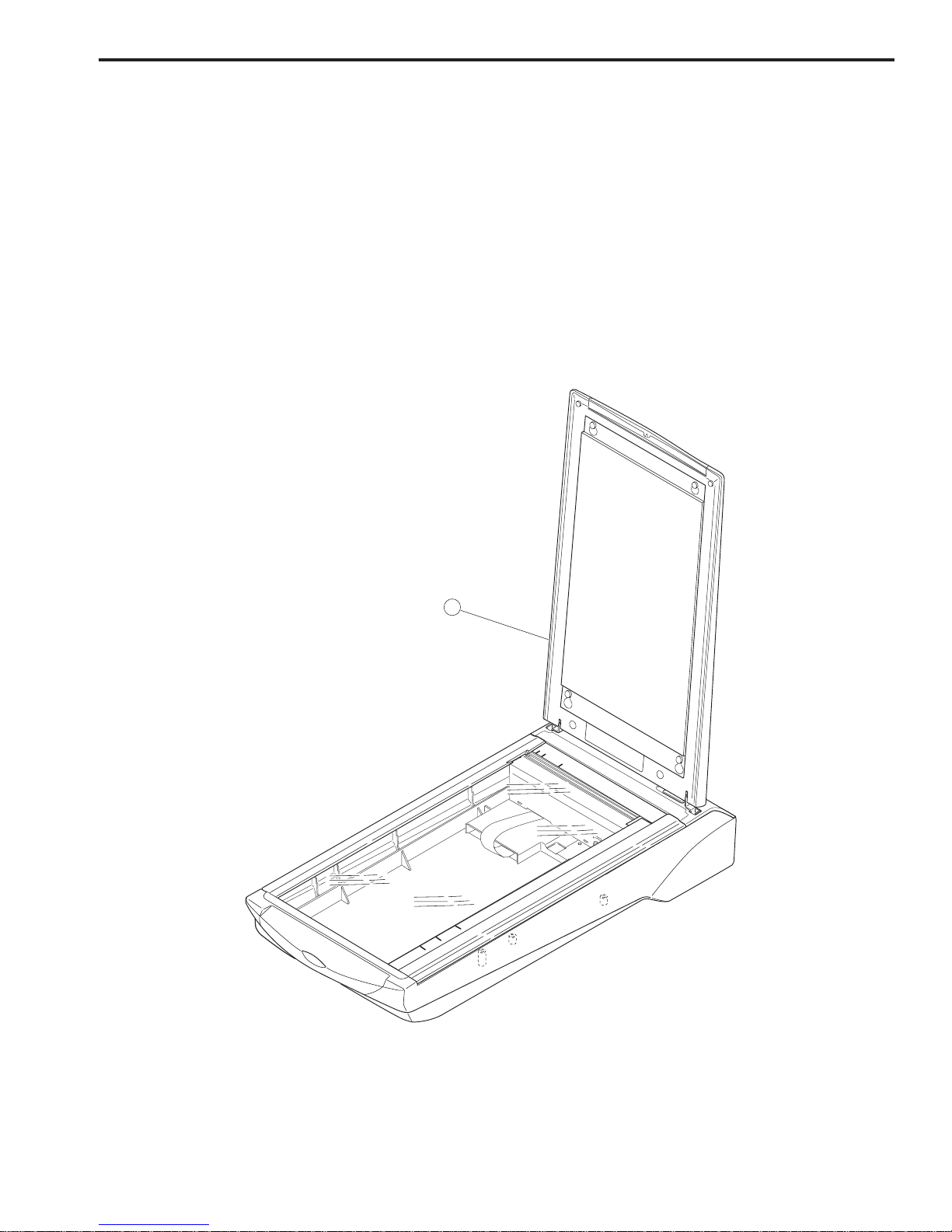
q FAU
E. Connecting FAU
1. Setting Up FAU
1) Remove the document cover and unlock the carriage lock.
2) Attach FAU to the scanner.
Figure 1-8
A4
LTR
B5
A4
B5
1
LTR
FAU cable is connected to the FAU connector on the scanner. Refer to the “Getting Started”
guide supplied with the product for details. For connecting the host computer’s cables, refer to
the manuals for the host computer.
CHAPTER 1
1 - 12
COPYRIGHT © 2001 CANON INC. CANOSCAN D1230U/D2400U MARCH 2001 PRINTED IN JAPAN (IMPRIME AU JAPON)
q FAU Cable
w FAU Connector
2. Connecting FAU Cable to FAU Connector on the Scanner
1) Connect the AC adapter cable to the power connector on the scanner.
2) Connect the FAU cable to the FAU connector on the scanner.
Figure 1-9
1
2
CHAPTER 1
1 - 13
COPYRIGHT © 2001 CANON INC. CANOSCAN D1230U/D2400U REV.0 MARCH 2001 PRINTED IN JAPAN (IMPRIME AU JAPON)
q Protective Cover
3) Remove the protective cover.
Figure 1-10
LTR
A4
LTR
B5
A4
B5
LTR
A4
LTR
B5
A4
B5
1

CHAPTER 1
1 - 14
COPYRIGHT © 2001 CANON INC. CANOSCAN D1230U/D2400U MARCH 2001 PRINTED IN JAPAN (IMPRIME AU JAPON)
IV. CUSTOMER’S DAILY MAINTENANCE
Dirt on the document glass may cause an unclear image or lines on an image. Clean the
document glass using the following steps.
1) Disconnect all cables from the scanner.
2) Wipe a dirt off the document glass with a soft clean cloth dampened with water and well
wrung.
3) Thoroughly wipe water off the document glass with a dry cloth.

COPYRIGHT © 2001 CANON INC. CANOSCAN D1230U/D2400U REV.0 MARCH 2001 PRINTED IN JAPAN (IMPRIME AU JAPON)
CHAPTER 2
OPERATION AND TIMING
I. BASIC OPERATION ........................2-1
A. Functions .................................2-1
B. Electrical System .....................2-2
C. Main PCB Input and Output ...2-4
D. Document Scanning
Sequence ................................. 2-6
II. OPTICAL SYSTEM .......................... 2-7
A. Outline ..................................... 2-7
B. Lamp Lighting Circuit .............. 2-8
C. FARE (Film Automatic Retouching
and Enhancement) ................. 2-10
D. Motor Control Circuit ............ 2-12
III. IMAGE PROCESSING .................... 2-13
A. Outline ................................... 2-13
B. Image Processing ................... 2-13
IV. CONTROL SYSTEM ...................... 2-20
A. Control System Diagram ........ 2-20
B. Main PCB ............................... 2-20
V. INTERFACE ................................... 2-21
A. Outline of USB Standard ........ 2-21
B. Benefits of USB Scanner ........ 2-21
C. Signal Definitions .................. 2-22
D. Interface Connection ............. 2-22
VI. POWER SUPPLY ........................... 2-23

CHAPTER 2
2 - 1
COPYRIGHT © 2001 CANON INC. CANOSCAN D1230U/D2400U REV.0 MAR. 2001 PRINTED IN JAPAN (IMPRIME AU JAPON)
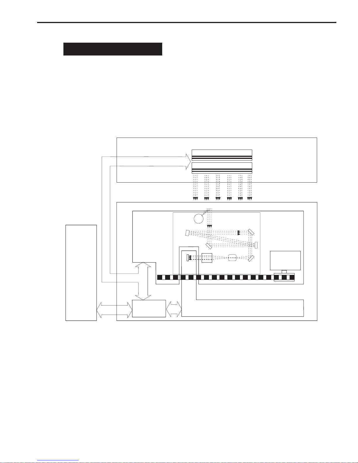
I. BASIC OPERATION
A. Functions
The scanner functions are divided into optical system, image processing system, and control
system.
Figure 2-1
Lens
CCD
BGR
B
G
R
Optical System
FAU
Drive
Motor
Scanning unit
Scanning
Lamp
Host
Computer
Control
System
Image Processing System
FARE Unit
FAU Lamp
IR LED
CHAPTER 2
2 - 2
COPYRIGHT © 2001 CANON INC. CANOSCAN D1230U/D2400U REV.0 MAR. 2001 PRINTED IN JAPAN (IMPRIME AU JAPON)
B. Electrical System
1. Outline
The scanner is not equipped with CPU. The device driver installed in the host computer
includes a control program, which functions as CPU. Host computer sends a command to the
ASIC via the USB controller, the ASIC controls the whole electrical circuits and image
processing of the scanner. The image signals read by the CCD are converted into digital data
by analog IC. The digital data is then processed by the ASIC and output to the host computer
via USB interface.
Figure 2-2
ASIC
USB
Controller
Regulator
Motor
Driver
FARE
Unit
Drive
Motor
CCD
PCB
Analog IC
Button PCB
AC Adapter
Host Computer
Start Button
Power LED
DRAM
Home
Position
Sensor
Control
Program
J2
JP9
JP1
JP8
JP2
Scanning
Lamp
Inverter
PCB
(D2400U only)
FAU
J1

CHAPTER 2
2 - 3
COPYRIGHT © 2001 CANON INC. CANOSCAN D1230U/D2400U REV.0 MAR. 2001 PRINTED IN JAPAN (IMPRIME AU JAPON)
2. Functions of the Main PCB
1) Analog IC
Converts the image signals (analog signals) read by the CCD into digital data.
- CDS (Correlated Double Sampling)
- AGC (Auto Gain Control)
- 16-bit A/D converter (Analog-to-Digital Converter)
2) ASIC
Performs various processings:
- DRAM control
- CCD timing clock creation
- Line buffer control
- CCD output line difference adjustment
- Image processing (Binary processing, Image inversion)
- Shading correction
- Motor driver control
3) DRAM
Stores the shading correction data when performing shading correction, and the image data
when scanning.
4) Motor Driver
Supplies power to the drive motor.
5) USB Controller
Controls data transfer between the host computer and ASIC.
CHAPTER 2
2 - 4
COPYRIGHT © 2001 CANON INC. CANOSCAN D1230U/D2400U REV.0 MAR. 2001 PRINTED IN JAPAN (IMPRIME AU JAPON)
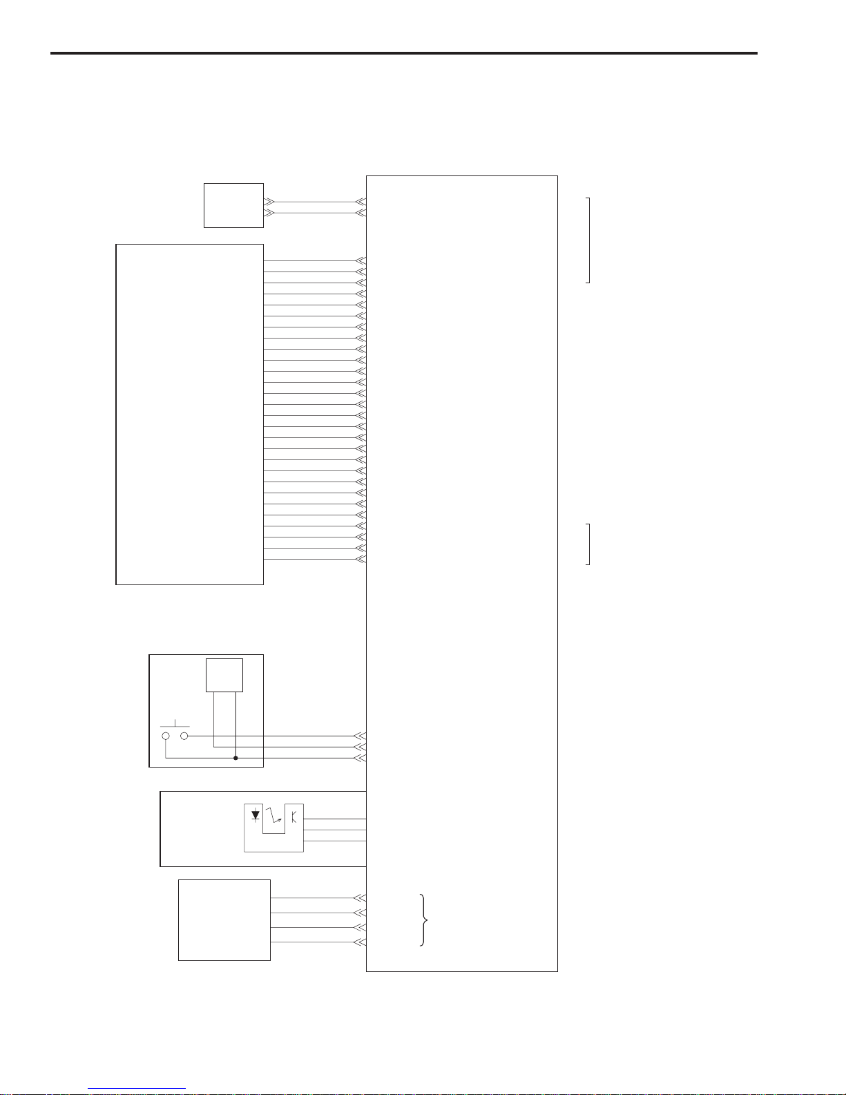
C. Main PCB Input and Output
1. CanoScan D1230U
Figure 2-3
JP8-1
-2
-3
-4
Drive Motor
Powe r
LED
Home Position
Sensor
"H" when scanning unitis in
home position
Drive motor drive signal
JP2-1
-2
-3
Start
Button
Button PCB
VCC
LED
HOTKEY0
+12V
GND
"H" when power LEDis ON
"H" when Star t button is pressed
Vbus
D-
D+
GND
J1-1
-2
-3
-4
-5
-6
-7
-8
XPAGND
XPAGND
FAU_DET
VCC
CN
XPAGND
XPAGND
XPAGND
AC Adapter
JP1-1
-2
-3
-4
-5
-6
-7
-8
-9
-10
-11
-12
-13
-14
-15
-16
-17
-18
-19
-20
-21
-22
-23
-24
-25
-26
-27
-28
LAMP_GND
LAMP_GND
12V_LAMP
12V_LAMP
+18VP
+18VP
C-DGND
PHI1
PHI2
PHI3
CN
C-DGND
AGND
CCD-SHB
CLB
CCD-SHG
RB
CCD-SHR
VCC
C-DGND
AGND
C-DGND
AGND
CCD_B
AGND
CCD_G
AGND
CCD_R
OUT1B
OUT1A
OUT2A
OUT2B
JP9-1
-2
-3
-4
To FAU
To Host
Computer
J2-1
-2
Main PCB
Scanning Unit
CHAPTER 2
2 - 5
COPYRIGHT © 2001 CANON INC. CANOSCAN D1230U/D2400U REV.0 MAR. 2001 PRINTED IN JAPAN (IMPRIME AU JAPON)
Figure 2-4
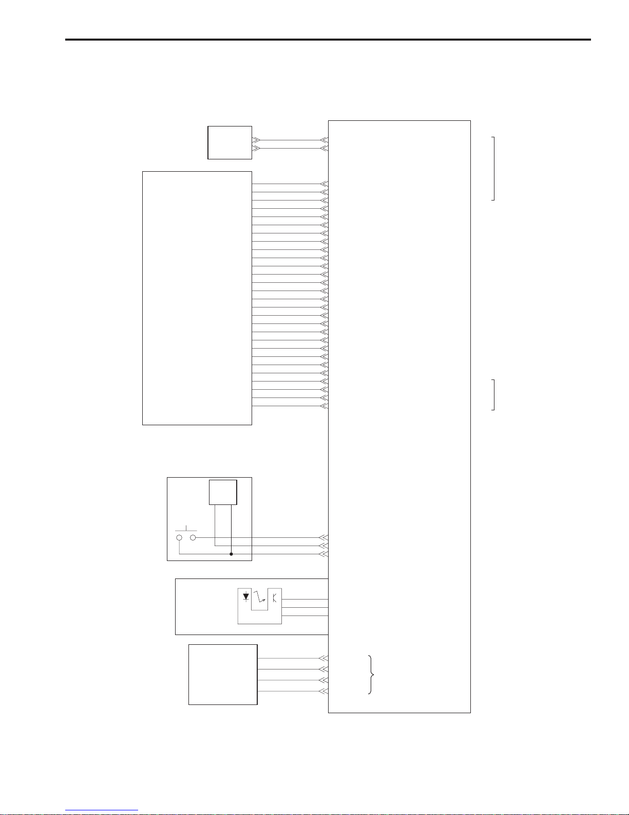
2. CanoScan D2400U
JP8-1
-2
-3
-4
Drive Motor
Power
LED
Home Position
Sensor
"H" when scanning unitis in
home position
Drive motor drive signal
JP2-1
-2
-3
Start
Button
Button PCB
VCC
LED
HOTKEY0
+12V
GND
"H" when power LEDis ON
"H" when Star t button is pressed
Vbus
D-
D+
GND
J1-1
-2
-3
-4
-5
-6
-7
-8
AC Adapter
JP1-1
-2
-3
-4
-5
-6
-7
-8
-9
-10
-11
-12
-13
-14
-15
-16
-17
-18
-19
-20
-21
-22
-23
-24
-25
-26
-27
-28
OUT1B
OUT1A
OUT2A
OUT2B
JP9-1
-2
-3
-4
To FAU
To Host
Computer
J2-1
-2
Main PCB
Scanning Unit
XPA
XPAGND
FAU_DET
VCC
IRLED
XPAGND
XPAGND
XPAGND
LAMP_GND
LAMP_GND
12V_LAMP
12V_LAMP
+18VP
+18VP
C-DGND
PHI1
PHI2
PHI3
+12V_VAROS
ASIC_VAROS
AGND
CCD-SHB
CLB
CCD-SHG
RB
CCD-SHR
VCC
C-DGND
AGND
C-DGND
AGND
CCD_B
AGND
CCD_G
AGND
CCD_R

CHAPTER 2
2 - 6
COPYRIGHT © 2001 CANON INC. CANOSCAN D1230U/D2400U REV.0 MAR. 2001 PRINTED IN JAPAN (IMPRIME AU JAPON)
D. Document Scanning Sequence
Figure 2-5
Table 2-1
*Standby *Scanning Unit ForwardSequence
Scan Command
Setup
Home Position
Sensor
Scanning Lamp
ON Signal
Drive Motor
Interface Signal
Standby
Scanning Unit
backward
Standby
Setup
Scanning Unit
Forward
Scanning Unit
backward
Seqence
After the scanner self test is
completed until the scanner
receives a scan command from
the host computer
From the scanner receives a
scan command until it starts
scanning
After the scanner starts scanning
until whole scan area specified
by the host computer is scanned
After the scanning unit starts
moving backward until it returns
to the home position
To maintain the scanner ready
for scan
To execute calibration for setting
light exposure time, gain data and
shading data
To execute image processing
according to the command from
the host computer while scanning
and send imada data to the
host computer
Remarks
Operation
The data is stored in DRAM
Purpose
To return the scanning unit to the
home position to ready for the
next scan
Home position is detected
by the home position sensor
CHAPTER 2
2 - 7
COPYRIGHT © 2001 CANON INC. CANOSCAN D1230U/D2400U REV.0 MAR. 2001 PRINTED IN JAPAN (IMPRIME AU JAPON)
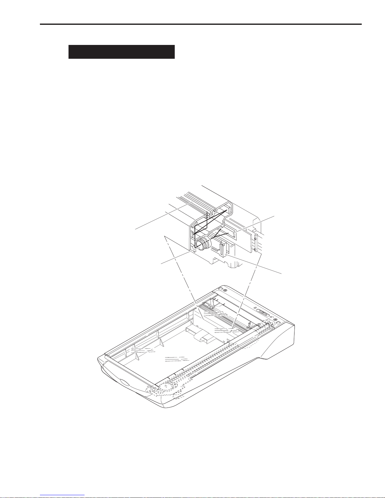
II. OPTICAL SYSTEM
A. Outline
The optical system consists of the scanning lamp, lens and mirrors. When scanning a
reflective document, the scanning lamp in the scanning unit exposes the document and
focuses the reflected light from the document on the light-sensitive device CCD (charge-coupled
device) via the lens and mirrors.
When scanning a film, FAU lamp in the Film Adapter Unit transmits the film and focuses the
transmitted light on the CCD.
When using FARE system, infrared LED transmits a film after FAU lamp does, and FARE unit
operates to scan the film.
Figure 2-6
LTR
A4
LTR
B5
A4
B5
CCD
Lens
FARE Unit
Scanning Lamp
 Loading...