

Canon AK1 Service Manual

Revision 2.0
Cassette Feeding Unit-AK1
Service Manual

Introduction
Important Notices
Application
This manual has been issued by Canon Inc. for qualified persons to learn technical theory, installation, maintenance, and repair
of products.
This manual covers all localities where the products are sold. For this reason, there may be information in this manual that does
not apply to your locality.
Corrections
This manual may contain technical inaccuracies or typographical errors due to improvements or changes in products.
When changes occur in applicable products or in the contents of this manual, Canon will release technical information as the
need arises. In the event of major changes in the contents of this manual over a long or short period, Canon will issue a new
edition of this manual.
The following paragraph does not apply to any countries where such provisions are inconsistent with local law.
Trademarks
The product names and company names used in this manual are the registered trademarks of the individual companies.
Copyright
This manual is copyrighted with all rights reserved. Under the copyright laws, this manual may not be copied, reproduced or
translated into another language, in whole or in part, without the consent of Canon Inc.
Copyright CANON INC. 2016
Caution
Use of this manual should be strictly supervised to avoid disclosure of confidential information.
Explanation of Symbols
The following symbols are used throughout this Service Manual.
Symbols Explanation Symbols Explanation
Check.
1x
Remove the claw.
Check visually.
1x
Insert the claw.
Check a sound. Push the part.
Introduction
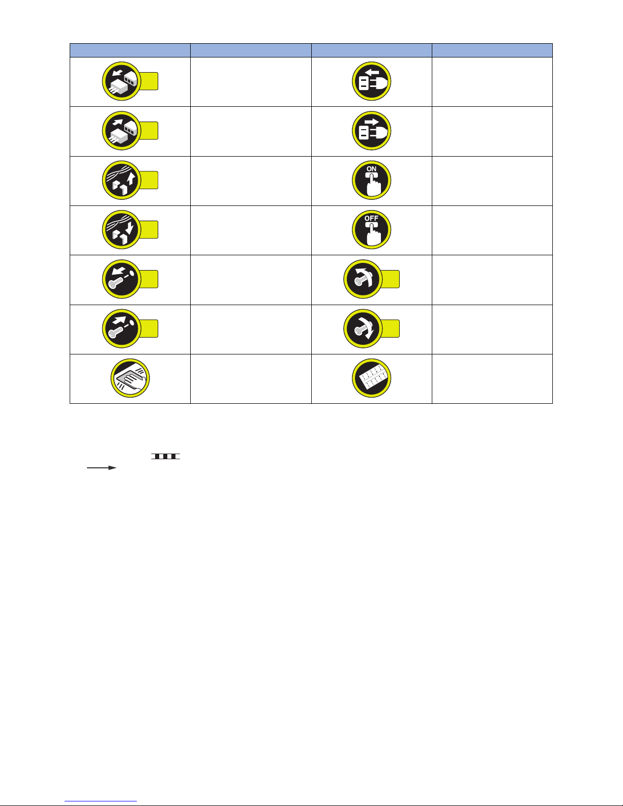
Symbols Explanation Symbols Explanation
1x
Disconnect the connector. Connect the power cable.
1x
Connect the connector. Disconnect the power cable.
1x
Remove the cable/wire from the
cable guide or wire saddle.
Turn on the power.
1x
Install the cable/wire to the cable
guide or wire saddle.
Turn off the power.
1x
Remove the screw.
1x
Loosen the screw.
1x
Install the screw.
1x
Tighten the screw.
Cleaning is needed. Measurement is needed.
The following rules apply throughout this Service Manual:
1. Each chapter contains sections explaining the purpose of specific functions and the relationship between electrical and
mechanical systems with reference to the timing of operation.
In the diagrams, represents the path of mechanical drive; where a signal name accompanies the symbol, the arrow
indicates the direction of the electric signal.
The expression "turn on the power" means flipping on the power switch, closing the front door, and closing the delivery unit
door, which results in supplying the machine with power.
2. In the digital circuits, '1' is used to indicate that the voltage level of a given signal is "High", while '0' is used to indicate "Low".
(The voltage value, however, differs from circuit to circuit.) In addition, the asterisk (*) as in "DRMD*" indicates that the DRMD
signal goes on when '0'.
In practically all cases, the internal mechanisms of a microprocessor cannot be checked in the field. Therefore, the operations
of the microprocessors used in the machines are not discussed: they are explained in terms of from sensors to the input of
the DC controller PCB and from the output of the DC controller PCB to the loads.
The descriptions in this Service Manual are subject to change without notice for product improvement or other purposes, and
major changes will be communicated in the form of Service Information bulletins.
All service persons are expected to have a good understanding of the contents of this Service Manual and all relevant Service
Information bulletins and be able to identify and isolate faults in the machine.
Introduction

Contents
Safety Precautions...............................................................................................1
Notes Before it Works Serving............................................................................................................ 2
Points to Note at Cleaning...................................................................................................................2
Notes on Assembly/Disassembly........................................................................................................2
1. Product Overview.............................................................................................3
Overview............................................................................................................................................. 4
Specifications....................................................................................................................................... 4
Parts Name.......................................................................................................................................... 4
Cross-section View............................................................................................................................... 5
2. Technology....................................................................................................... 7
Basic Configuration............................................................................................................................. 8
Parts Configuration............................................................................................................................... 8
Paper Path......................................................................................................................................... 11
Controls.............................................................................................................................................12
Overview............................................................................................................................................ 12
Jam Detection.....................................................................................................................................18
3. Periodical Service.......................................................................................... 19
List of Periodical Service Works........................................................................................................20
4. Disassembly/Assembly................................................................................. 21
List of Parts....................................................................................................................................... 22
External View......................................................................................................................................22
List of Main Unit.................................................................................................................................. 23
Electrical Components.........................................................................................................................24
List of Connectors............................................................................................................................... 27
Removal from the Connected Equipment ........................................................................................ 29
Procedure...........................................................................................................................................29
External Cover System......................................................................................................................33
Removing the Rear Cover....................................................................................................................33
Removing the Cassette Right Cover.....................................................................................................33
Controller System..............................................................................................................................37
Removing the Cassette Module Controller PCB.................................................................................... 37
Pickup Feed System......................................................................................................................... 38
Removing the Cassette Pickup Roller / Cassette Separation Roller / Cassette Feed Roller...................... 38
Removing the Cassette Auto Close Unit............................................................................................... 42
Removing the Pickup Unit....................................................................................................................44
Removing the Cassette 2 Pickup Motor (M102).....................................................................................47
Removing the Cassette 3, 4 Pickup Motor (M101)................................................................................. 48
Removing the Cassette 2 Lifter Motor (M104)....................................................................................... 49
Removing the Cassette 3, 4 Lifter Motor (M103)....................................................................................50
Contents
i

Removing the Cassette 2 Pullout Motor (M106).....................................................................................50
Removing the Cassette 3, 4 Pullout Motor (M105).................................................................................51
Removing the Cassette 2 Pickup Drive Unit.......................................................................................... 51
Removing the Cassette 3, 4 Pickup Drive Unit...................................................................................... 53
Removing the Vertical Path Drive Unit.................................................................................................. 54
5. Adjustment..................................................................................................... 57
Pickup Feed System......................................................................................................................... 58
Cassette Left Edge Margin Adjustment (1st Side: Mechanical Adjustment)............................................. 58
Cassette Left Edge Margin Adjustment (1st Side: Software Adjustment)................................................. 60
Cassette Left Edge Margin Adjustment (2nd Side: Software Adjustment)................................................ 61
Leading Edge Margin Adjustment (1st Side of Plain Paper)....................................................................61
Leading Edge Margin Adjustment (2nd side)......................................................................................... 62
APPENDICES......................................................................................................63
Service Tools.....................................................................................................................................64
Special Tools...................................................................................................................................... 64
Solvent/Oil List....................................................................................................................................64
General Circuit Diagram....................................................................................................................65
Contents
ii

Safety Precautions
Notes Before it Works Serving..............2
Points to Note at Cleaning.................... 2
Notes on Assembly/Disassembly..........2

Notes Before it Works Serving
• At servicing, be sure to turn OFF the power source according to the specified steps and disconnect the power plug.
• Be sure to disconnect the power plug on a regular basis and remove dust and dirt accumulated around the outlet with dry
cloth.
CAUTION:
Leaving the power plug connected for a long time in an environment having a lot of dust, moisture, or oily smoke will
cause a fire. (Because dust accumulated in the surrounding area will absorb moisture and cause an insulation failure)
Points to Note at Cleaning
When performing cleaning using organic solvent such as alcohol, be sure to check that the component of solvent is vaporized
completely before assembling.
Notes on Assembly/Disassembly
Follow the items below to assemble/disassemble the device.
1. Disconnect the power plug to avoid any potential dangers during assembling/disassembling works.
2. If not specially instructed, reverse the order of disassembly to reinstall.
3. Ensure to use the right screw type (length, diameter, etc.) at the right position when assembling.
4. To keep electric conduction, binding screws with washers are used to attach the grounding wire and the varistor. Ensure to
use the right screw type when assembling.
5. Unless it is specially needed, do not operate the device with some parts removed.
6. Never remove the paint-locked screws when disassembling.
Safety Precautions
2

Product Overview
1
Overview............................................... 4
Overview
Specifications
Item Description
Paper storage method Front-loading method
Pickup method Retard separation
Stacking capacity 550 sheets (80 g/m2) x 3 cassettes
Paper feed reference Center reference
Paper size Width: 98.4 mm to 216.0 mm
Length: 148.0 mm to 355.6 mm
A4-R, A5-R, B5-R, LGL, LTR-R, STMT-R, EXEC-R, 16K
Special paper standard size
Paper weight 60 to 163 g/m2
Paper size switching Auto switching
2-sided print method Through path
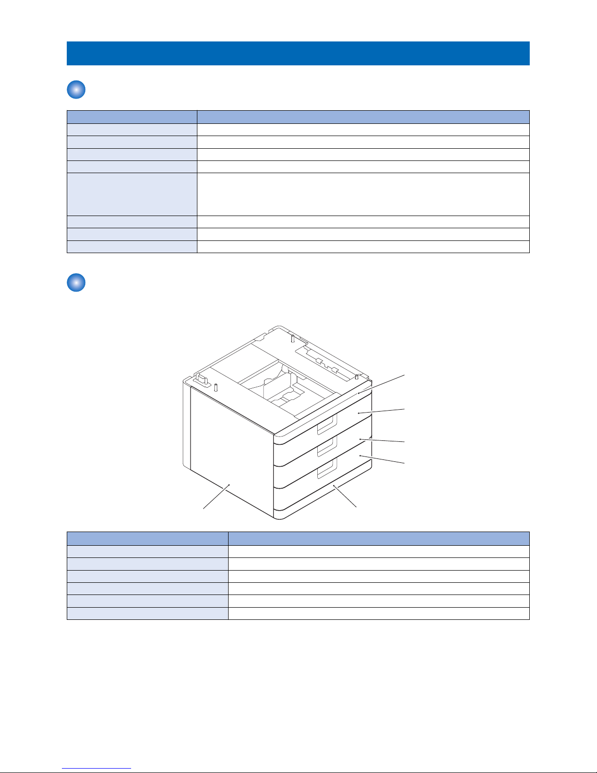
Parts Name
■ External View
[5]
[6]
[1]
[2]
[3]
[4]
No. Parts Name
[1] Cassette Front Upper Cover
[2] Cassette Front Upper Tray Cover
[3] Cassette Front Middle Tray Cover
[4] Cassette Front Lower Tray Cover
[5] Cassette Front Lower Cover
[6] Left Over
1. Product Overview
4
[8]
[9]
[10]
[11]
[7]
No. Parts Name
[7] Connector Cover
[8] Rear Cover
[9] Right Lower Cover
[10] Cassette Right Cover
[11] Right front cover
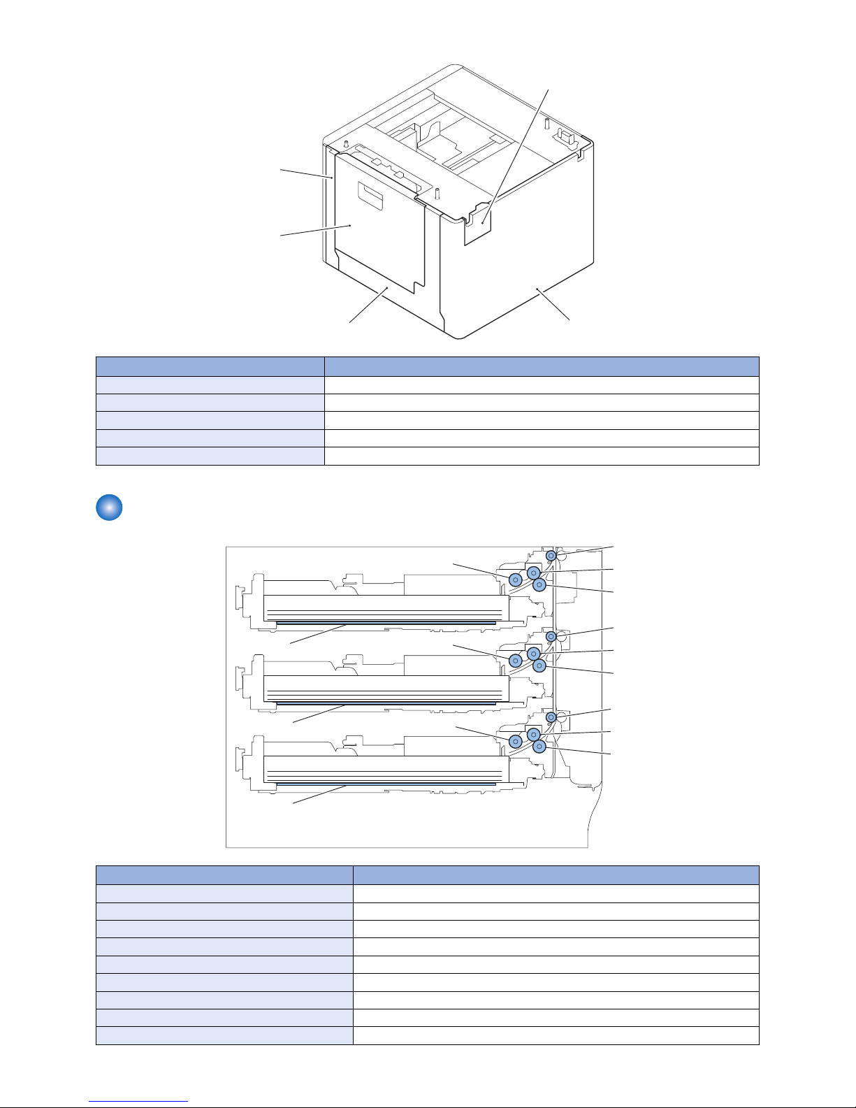
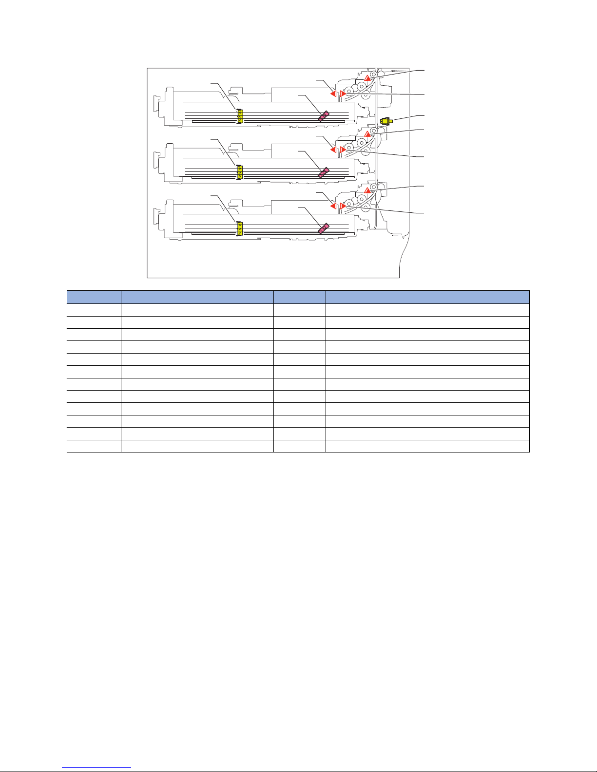
Cross-section View
[1]
[2]
[4]
[3]
[6]
[7]
[9]
[8]
[5]
[12]
[11]
[10]
[15]
[13]
[14]
No. Parts Name
[1] Cassette 2 pickup Roller
[2] Cassette 2 vertical path Roller
[3] Cassette 2 feed Roller
[4] Cassette 2 separation Roller
[5] Cassette 2 Liftnig Plate
[6] Cassette 3 pickup Roller
[7] Cassette 3 vertical path Roller
[8] Cassette 3 feed Roller
[9] Cassette 3 separation Roller
1. Product Overview
5

No. Parts Name
[10] Cassette 3 Liftnig Plate
[11] Cassette 4 pickup Roller
[12] Cassette 4 vertical path Roller
[13] Cassette 4 feed Roller
[14] Cassette 4 separation Roller
[15] Cassette 4 Liftnig Plate
1. Product Overview
6

Technology
2
Basic Configuration...............................8
Controls...............................................12
Basic Configuration
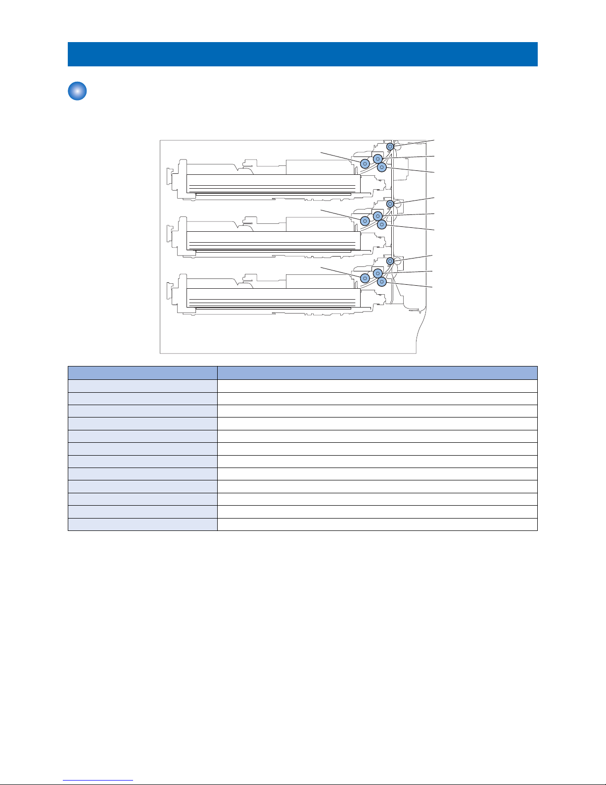
Parts Configuration
■ Rollers Layout drawing
[1]
[2]
[4]
[3]
[5]
[6]
[8]
[7]
[9]
[10]
[11]
[12]
No. Parts Name
[1] Cassette 2 pickup Roller
[2] Cassette 2 vertical path Roller
[3] Cassette 2 feed Roller
[4] Cassette 2 separation Roller
[5] Cassette 3 pickup Roller
[6] Cassette 3 vertical path Roller
[7] Cassette 3 feed Roller
[8] Cassette 3 separation Roller
[9] Cassette 4 pickup Roller
[10] Cassette 4 vertical path Roller
[11] Cassette 4 feed Roller
[12] Cassette 4 separation Roller
2. Technology
8
■ Sensors Layout Drawing
PS104
SW101
PS110
SW104
PS101
PS107
PS105
SW102
PS111
PS102
PS108
PS106
SW103
PS112
PS103
PS109
No. Parts Name No. Parts Name
PS101 Cassette 2 Pullout Sensor SW101 Cassette 2 Size Detection Switch
PS102 Cassette 3 Pullout Sensor SW102 Cassette 3 Size Detection Switch
PS103 Cassette 4 Pullout Sensor SW103 Cassette 4 Size Detection Switch
PS104 Cassette 2 Paper Sensor SW104 Cassette Right Door Open/Close Detection Switch
PS105 Cassette 3 Paper Sensor
PS106 Cassette 4 Paper Sensor
PS107 Cassette 2 Paper Surface Sensor
PS108 Cassette 3 Paper Surface Sensor
PS109 Cassette 4 Paper Surface Sensor
PS110 Cassette 2 Paper Level Sensor
PS111 Cassette 3 Paper Level Sensor
PS112 Cassette 4 Paper Level Sensor
2. Technology
9

■ Route of Drive
M102
M106
M104
M105
M103
M101
No. Parts Name
M101 Cassette 3, 4 pickup Motor
M102 Cassette 2 pickup Motor
M103 Cassette 3, 4 Lifter Motor
M104 Cassette 2 Lifter Motor
M105 Cassette 3, 4 Pullout Motor
M106 Cassette 2 Pullout Motor
2. Technology
10
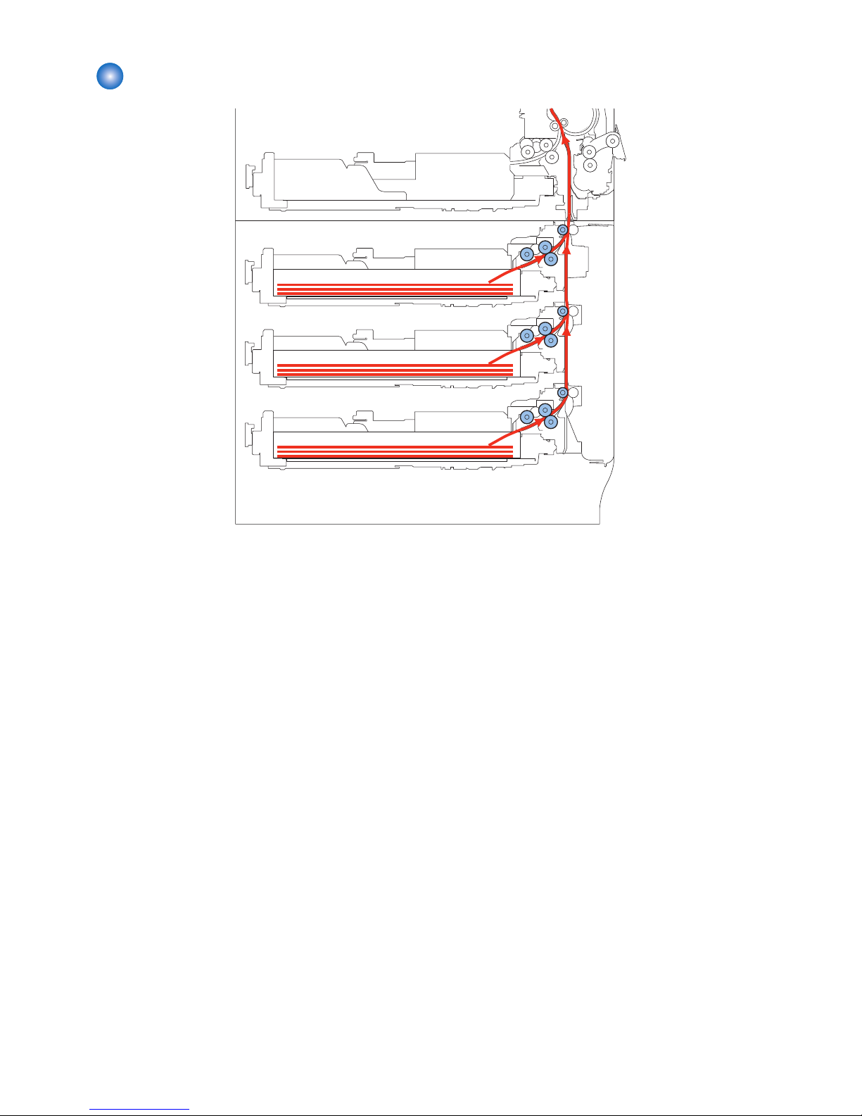
Paper Path
Pickup from Cassette 2
Pickup from Cassette 3
Pickup from Cassette 4
2. Technology
11
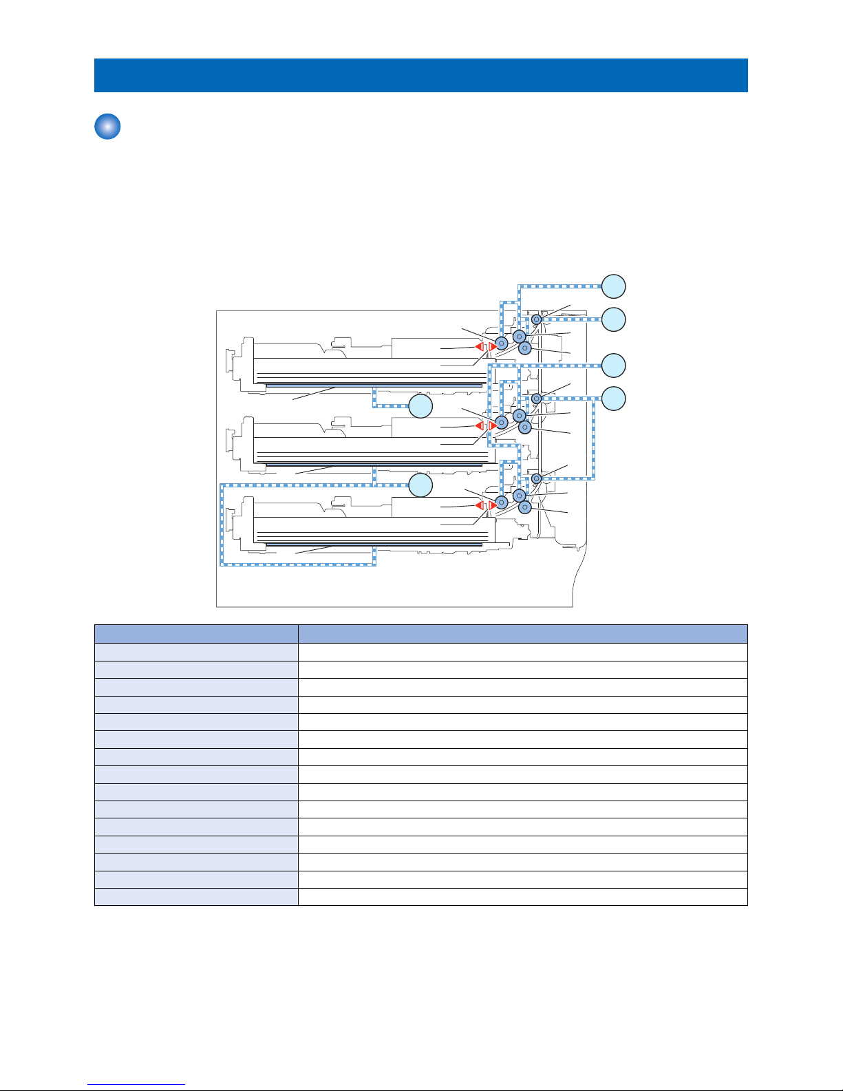
Controls
Overview
Paper inside a cassette is lifted up by the Lifter Plate.
The Lifter Plate is lifted up by rotating the Cassette Lifter Motor (M103/M104). When the Pickup Roller comes into contact with
the paper surface, the Cassette Pickup Motor (M101/M102) rotates to pick up the surface layer paper, and the Cassette Feed
Roller and Cassette Separation Roller feed only 1 sheet of paper to the feed path. Then, it is moved to the Pre-registration Roller
by the rotation of the Cassette Pullout Motor (M105/M106).
The Cassette Pickup Roller, Cassette Feed Roller, and Cassette Separation Roller are driven by the Cassette Pickup Motor
(M101/M102) while the Cassette Vertical Path Roller is operated by the rotation of the Cassette Pullout Motor (M105/M106).
M102
M106
M104
M105
M103
M101
[1]
[2]
[4]
[3]
[6]
[7]
[9]
[8]
[5]
[12]
[11]
[10]
[15]
[13]
[14]
PS104
PS107
PS105
PS108
PS106
PS109
No. Parts Name
[1] Cassette 2 Pickup Roller
[2] Cassette 2 Vertical Path Roller
[3] Cassette 2 Feed Roller
[4] Cassette 2 Separation Roller
[5] Cassette 2 Liftnig Plate
[6] Cassette 3 Pickup Roller
[7] Cassette 3 Vertical Path Roller
[8] Cassette 3 Feed Roller
[9] Cassette 3 Separation Roller
[10] Cassette 3 Liftnig Plate
[11] Cassette 4 Pickup Roller
[12] Cassette 4 Vertical Path Roller
[13] Cassette 4 Feed Roller
[14] Cassette 4 Separation Roller
[15] Cassette 4 Liftnig Plate
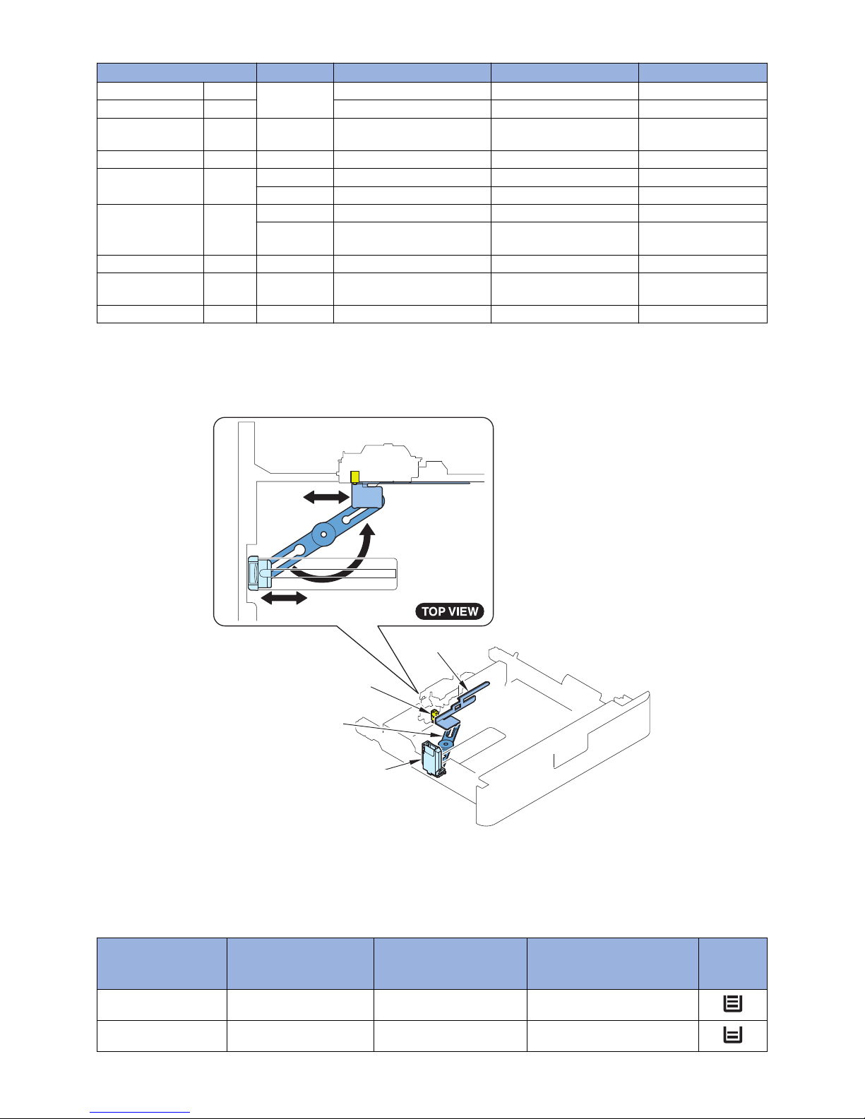
■ Paper Size Detection Control
The paper size in the cassette is automatically detected by the "Cassette Size Switch" after the position of the Guide Plate is
adjusted and the cassette is installed in the host machine.
By shifting the Guide Plate, concavo-convex area of the Cassette Size Dial is switched and the Cassette Size Switch at the printer
side is switched. The switch consists of 3 microswitches, and the length is detected in accordance with the combination of ON/
2. Technology
12
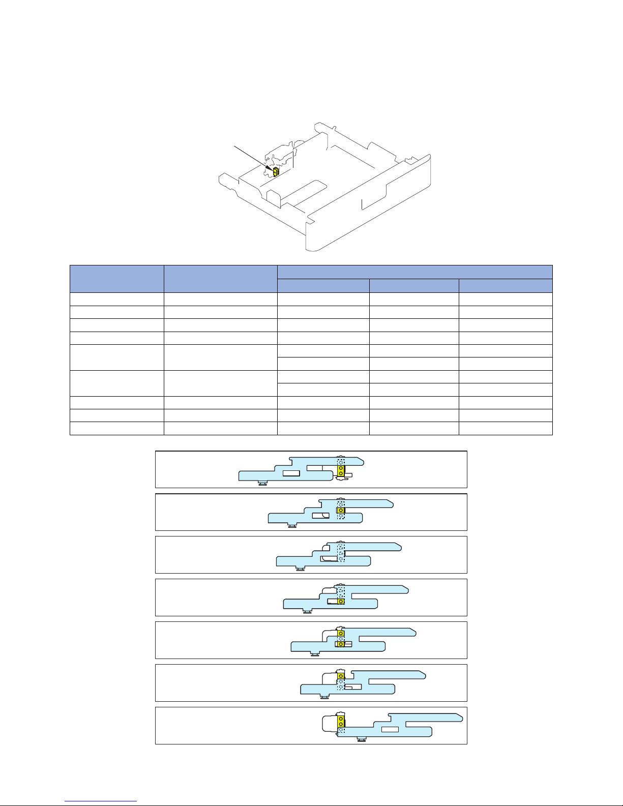
OFF. (When the switch is pressed: ON) Any standard size paper of AB, inch, or AK configuration can be used. However, distinction
between A5-R and STMT-R should be made manually on the check screen. Distinction between EXEC-R and 16K-R and between
LTR-R and 16K-R is automatically made according to the country setting.
*: Whether to select A5-R or STMT-R can be registered in the user mode setting.
[Settings/Registration] > [Preferences] > [Paper Settings] > [A5R/STMTP Paper Selection]
Specify A5-R or STMT-R for each cassette.
Cassette Size Switch
Size Length Length Detection
1 2 3
A5-R 210 ON OFF OFF
STMT-R 215.9 ON OFF OFF
B5-R 257.0 ON OFF ON
EXEC-R 267.0 ON ON ON
16K-R 270.0
ON ON ON
ON ON OFF
LTR-R 279.4
ON ON OFF
OFF ON OFF
A4-R 297.0 OFF ON ON
LGL 355.6 OFF OFF ON
(No cassette) ‐ OFF OFF OFF
LGL
A4-R
LTR-R
B5-R
A5-R
STMT-R
EXEC-R
16K-R
16K-R
LTR-R
2. Technology
13
Paper size *1 All modes AB configuration Inch configuration AK configuration
A5-R 210
1
1 ‐ 1
STMT-R 215.9 ‐ 1 ‐
B5-R 257.0 2 2 Improper loading of paper
Improper loading of pa-
per
EXEC-R 267.0 3 Improper loading of paper 3 ‐
16K-R 270.0
3 Improper loading of paper ‐ 3
4 Improper loading of paper ‐ 4
LTR-R 279.4
4 Improper loading of paper 4 ‐
5 Improper loading of paper 5
Improper loading of pa-
per
A4-R 297.0 6 6 Improper loading of paper 6
LGL 355.6 7 Improper loading of paper 7
Improper loading of pa-
per
(No cassette) *2 ‐ 8 ‐ ‐ ‐
*1: The paper size can be registered in user mode.
Settings/Registration > Preferences > Paper Settings > Paper Settings
*2: Presence of the cassette is detected when the size switch is pressed.
(When none of the switches are pressed, it is judged as "no cassette".)
Guide Plate
Link Arm
Size Plate
Cassette
Size Switch
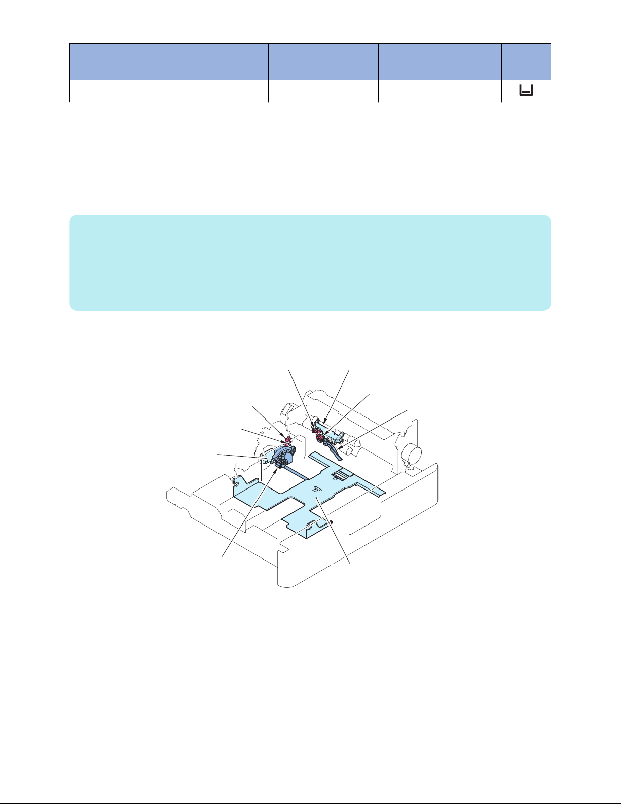
■ Paper Level Detection Control
Paper level inside the cassette is detected by the sensors shown in the following table.
The level of paper in the cassette is detected by the Cassette Lifter Motor, Cassette Paper Sensor, Cassette Paper Surface
Sensor, and Cassette Paper Level Sensor.
Cassette Paper Sen-
sor
Cassette Paper Surface
Sensor
Cassette Paper Level Sen-
sor
Paper level Display on
the Control
Panel
OFF ON OFF * 100% to 50% of the capacity*
OFF ON OFF Approx. 50% to approx. 50 sheets
2. Technology
14
Cassette Paper Sen-
sor
Cassette Paper Surface
Sensor
Cassette Paper Level Sen-
sor
Paper level Display on
the Control
Panel
OFF ON ON Approx. 50 sheets or less
The control that switches the paper level display on the Control Panel is as follows:
• When the icon displayed on the Control Panel shows 3 bars or 2 bars:
The paper level is detected based on the time for which the Cassette Lifter Motor remains ON. Or, the paper level is detected
based on the time from when the Cassette Paper Sensor is turned ON to when the Cassette Paper Surface Sensor is turned
ON.
The paper level during paper feed is detected based on the signal status of the Cassette Paper Level Sensor that changes as
the Cassette Lifter Plate is lifted up.
NOTE:
Related service mode:
*: The level of paper in the cassette is displayed by executing the following service mode.
When to change the icon from "3 bars" to "2 bars" can be adjusted.
Level 2 > COPIER > ADJUST > CST-ADJ > CST-VLMX (Adjustment of the threshold value for detecting the level of paper
in the Cassette X)
X indicates the cassette number (1 to 4).
• When the icon displayed on the Control Panel shows 2 bars or 1 bar:
The icon displayed on the Control Panel changes to "1 bar" when the Cassette Paper Level Sensor is turned ON.
Lifting Plate
Detection Lever
Paper Detection Lever
Lifting Plate
Lifter Gear
Paper Level
Detection Lever
Cassette Paper
Level Sensor
Cassette Paper
Surface Sensor
Cassette
Lifter Motor
Cassette
Paper Sensor
2. Technology
15
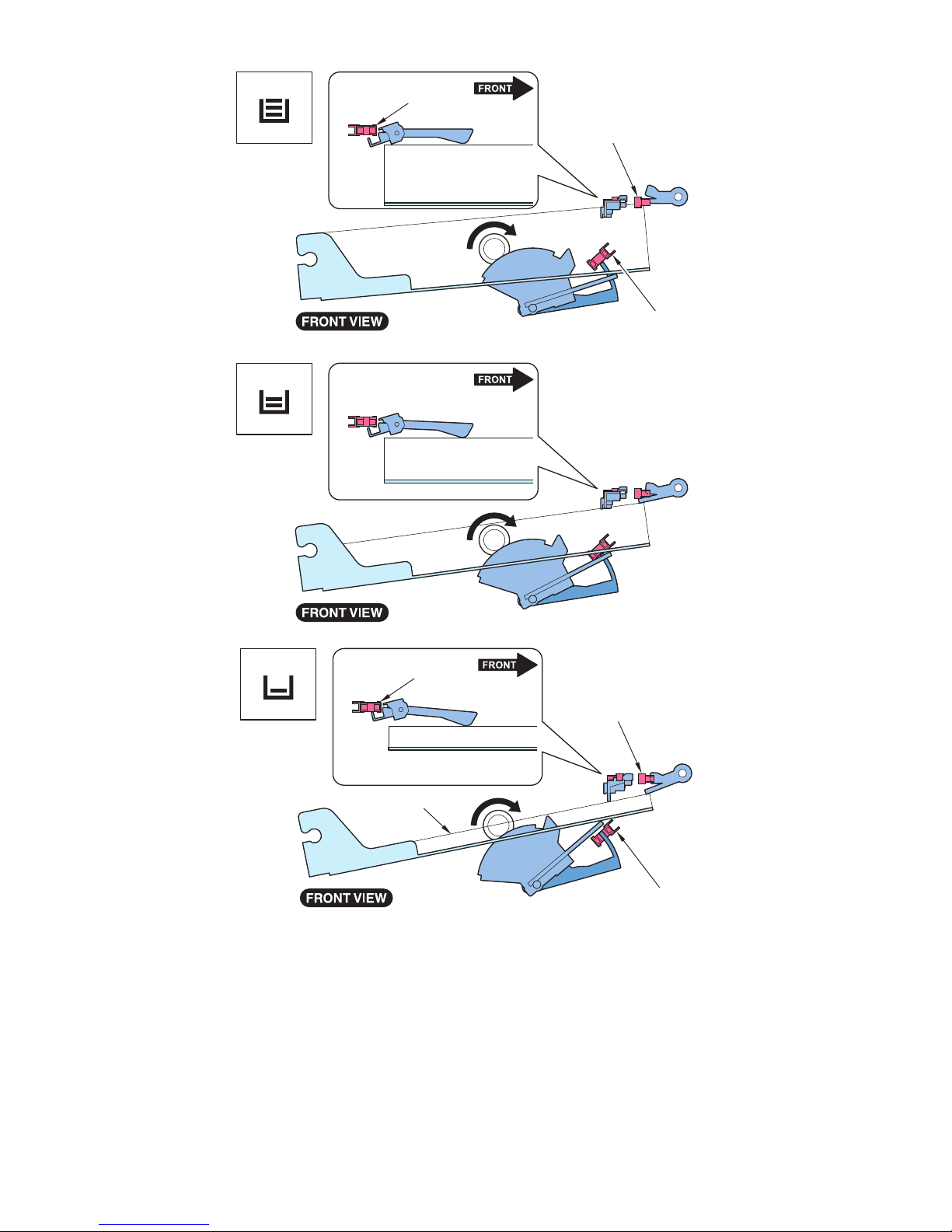
OFF
OFF
OFF
OFF
OFF
OFF
Cassette
Paper Sensor
Paper
Paper
Cassette Paper
Surface Sensor
Cassette Paper
Level Sensor
OFF
OFF
ON
Cassette
Paper Sensor
Paper
Paper
Cassette Paper
Surface Sensor
Cassette Paper
Level Sensor
■ Paper Detection Control
Paper is detected by the Cassette Size Switch, Cassette Paper Surface Sensor and Cassette Paper Sensor.
The absence of paper is notified when the Cassette Paper Sensor is turned ON at the time the Cassette Size Switch is turned
ON (it is detected that the cassette is in the host machine) and the Cassette Paper Surface Sensor is turned OFF (the Lifter Plate
is raised to the pickup position).
2. Technology
16
 Loading...