

Cassette Feeding Unit-AG1
Product Outline
Technology
Periodic Servicing
Parts Replacing and Cleaning
Adjustment
Installation
Appendix
June 25, 2014
Revision 0
Service Manual
654321

Application
This manual has been issued by Canon Inc. for qualied persons to learn technical theory,
installation, maintenance, and repair of products. This manual covers all localities where the
products are sold. For this reason, there may be information in this manual that does not
apply to your locality.
Corrections
This manual may contain technical inaccuracies or typographical errors due to improvements
or changes in products. When changes occur in applicable products or in the contents of this
manual, Canon will release technical information as the need arises. In the event of major
changes in the contents of this manual over a long or short period, Canon will issue a new
edition of this manual.
The following paragraph does not apply to any countries where such provisions are
inconsistent with local law.
Trademarks
The product names and company names used in this manual are the registered trademarks
of the individual companies.
Copyright
This manual is copyrighted with all rights reserved. Under the copyright laws, this manual may
not be copied, reproduced or translated into another language, in whole or in part, without the
consent of Canon Inc.
© CANON INC. 2014
Caution
Use of this manual should be strictly supervised to avoid disclosure of condential
information.
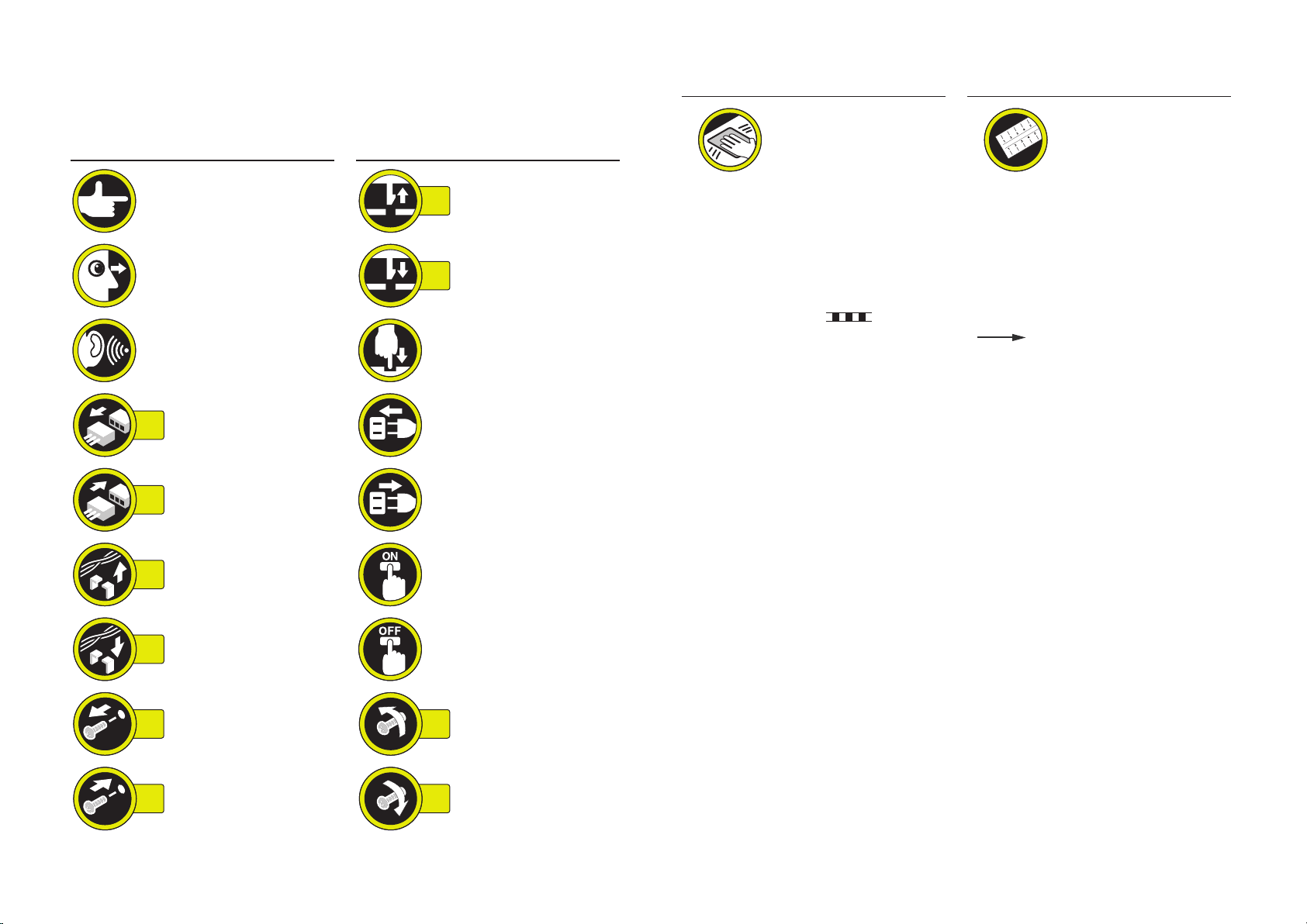
Explanation of Symbols
The following symbols are used throughout this Service Manual.
Symbols Explanation Symbols Explanation
Symbols Explanation Symbols Explanation
Check.
Check visually.
Check a sound. Push the part.
Disconnect the connector. Connect the power cable.
1x
Connect the connector.
1x
Remove the cable/wire
from the cable guide or wire
1x
saddle.
Remove the claw.
1x
Insert the claw.
1x
Disconnect the power
cable.
Turn on the power.
Cleaning is needed. Measurement is needed.
The following rules apply throughout this Service Manual:
1. Each chapter contains sections explaining the purpose of specic functions and the
relationship between electrical and mechanical systems with reference to the timing of
operation.
In the diagrams,
name accompanies the symbol, the arrow
electric signal.
The expression "turn on the power" means ipping on the power switch, closing the
front door, and closing the delivery unit door, which results in supplying the machine with
power.
2. In the digital circuits, '1' is used to indicate that the voltage level of a given signal is
"High", while '0' is used to indicate "Low". (The voltage value, however, differs from
circuit to circuit.) In addition, the asterisk (*) as in "DRMD*" indicates that the DRMD
signal goes on when '0'.
In practically all cases, the internal mechanisms of a microprocessor cannot be checked
in the eld. Therefore, the operations of the microprocessors used in the machines
are not discussed: they are explained in terms of from sensors to the input of the DC
controller PCB and from the output of the DC controller PCB to the loads.
represents the path of mechanical drive; where a signal
indicates the direction of the
Install the cable/wire to the
1x
cable guide or wire saddle.
Remove the screw.
1x
Install the screw.
1x
Turn off the power.
Loosen the screw.
1x
Tighten the screw.
1x
The descriptions in this Service Manual are subject to change without notice for product
improvement or other purposes, and major changes will be communicated in the form of
Service Information bulletins.
All service persons are expected to have a good understanding of the contents of this Service
Manual and all relevant Service Information bulletins and be able to identify and isolate faults
in the machine.

Contents
0 Safety Precautions
Notes Before it Works Serving ---------------------------------------------0-2
1 Product Outline
Outline ---------------------------------------------------------------------------1-2
Specication ------------------------------------------------------------------------- 1-2
Names of Parts ----------------------------------------------------------------1-2
External View ----------------------------------------------------------------------- 1-2
Cross-section View ---------------------------------------------------------------- 1-3
Removing the Rear Cover ------------------------------------------------------- 4-9
Removing the Cassette Receptacle ------------------------------------------- 4-9
Removing the Vertical Path Unit ---------------------------------------------- 4-10
Removing the Cassette 2 Pickup Roller /
Cassette 2 Separation Roller / Cassette 2 Feed Roller -----------------4-13
Removing the Cassette 2 Pickup Unit ---------------------------------------4-16
Removing the Cassette 2 Pickup Motor (M102) --------------------------4-18
Removing the Cassette 2 Lifter Motor (M104)-----------------------------4-18
Removing the Cassette 2 Pullout Motor (M106) -------------------------- 4-19
Removing the Cassette 2 Pickup Drive Unit ------------------------------- 4-19
Removing the Cassette 2 Auto Close Unit ---------------------------------4-20
Removing the Cassette Module Controller PCB -------------------------- 4-21
5 Adjustment
2 Technology
Basic conguration -----------------------------------------------------------2-2
Parts Conguration ---------------------------------------------------------------- 2-2
Paper Path --------------------------------------------------------------------------- 2-3
Controls --------------------------------------------------------------------------2-4
Overview ----------------------------------------------------------------------------- 2-4
Jam Detection --------------------------------------------------------------------- 2-11
Work of Service -------------------------------------------------------------------2-12
3 Periodic Servicing
Periodic Servicing List -------------------------------------------------------3-2
4 Parts Replacing and Cleaning
List of Parts ---------------------------------------------------------------------4-2
External View ----------------------------------------------------------------------- 4-2
List of Main Unit -------------------------------------------------------------------- 4-3
Electrical Components ------------------------------------------------------------ 4-3
List of Connectors ----------------------------------------------------------------- 4-5
Disassembly/Assembly ------------------------------------------------------4-6
Layout Drawing --------------------------------------------------------------------- 4-6
Disconnecting from the Host Machine ---------------------------------------- 4-7
Pickup Feed System ---------------------------------------------------------5-2
Setting method when the size detection patterns are overlapped ----- 5-2
Cassette Left Edge Margin Adjustment
(1st side; Mechanical Adjsutment) --------------------------------------------- 5-3
Cassette Left Edge Margin Adjustment
(1st side; Software Adjsutment) ------------------------------------------------ 5-5
Cassette Left Edge Margin Adjustment
(2nd side; Software Adjsutment) ----------------------------------------------- 5-6
Lead-edge Margin Adjustment (1st side/normal paper) ------------------ 5-6
Lead-edge Margin Adjustment (2nd side) ----------------------------------- 5-7
6 Installation
Installing this Equipment ----------------------------------------------------6-2
Appendix
Service Tools --------------------------------------------------------------------- II
Special Tools --------------------------------------------------------------------------- II
Solvents and Oils --------------------------------------------------------------------- II
General Circuit Diagram -------------------------------------------------------III

Safety Precautions
Notes Before it Works Serving
■

Notes Before it Works Serving
CAUTION:
At servicing, be sure to turn off the power source according to the specied steps and
disconnect the power plug.
CAUTION:
Do not turn off the power switch (of the host machine) when downloading is under way.
Turning off the main power switch while downloading is under way can disable the
machine.
0-2
0-2

Product Outline
1
Outline
■
Names of Parts
■
Product Outline
1
1
Product Outline > Names of Parts > External View
1-2
Outline
Specication
Item Description
Paper storage method
Pickup method
Paper stack capacity
Paper feed reference
Paper size
Paper grammage
Paper size switch
Duplexing method
Front loading method
Retard separation method
550 sheets (80 g/m2)
Center reference
Width: 98.4 mm to 216.0 mm
Length: 148.0 mm to 355.6 mm
A4-R, A5-R, B5-R, LGL, LTR-R, STMT-R, EXEC-R, 16K, special
standard-size
60 g/m2 to 163 g/m
By the user
Through path
2
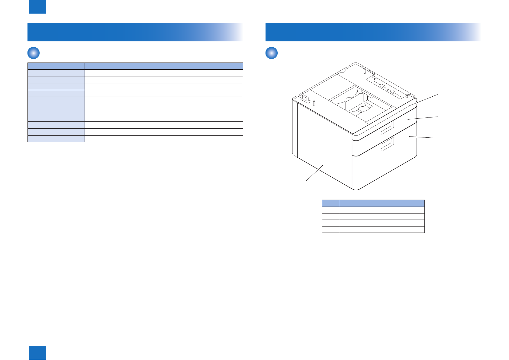
Names of Parts
External View
[1]
[2]
[3]
T-1-1
[4]
F-1-1
No. Parts Name
[1] Cassette Front Upper Cover
[2] Upper Tray Cover
[3] Lower Tray Cover
[4] Left Over
T-1-2
Product Outline > Names of Parts > External View
1
1-2
1
Product Outline > Names of Parts > Cross-section View
1-3
[9]
[8]
[7]
No. Parts Name
[5] Connector Cover
[6] Rear Cover
[7] Right Lower Cover
[8] Cassette Right Cover
[9] Right front cover
T-1-3
[5]
[6]
F-1-2
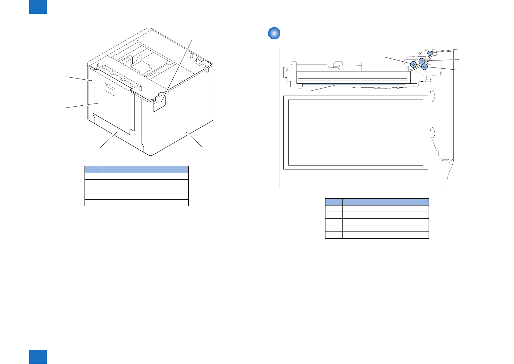
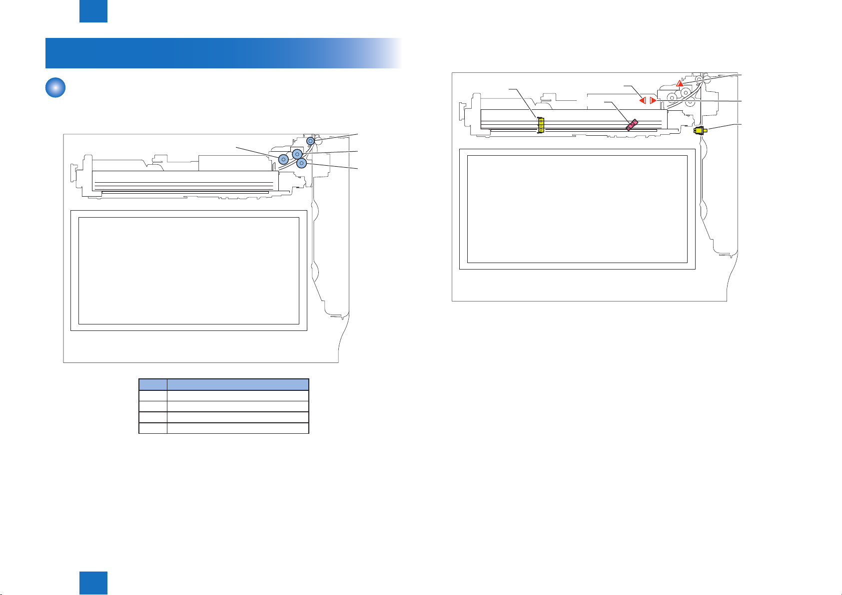
Cross-section View
[5]
No. Parts Name
[1] Cassette 2 pickup Roller
[2] Cassette 2 vertical path Roller
[3] Cassette 2 feed Roller
[4] Cassette 2 separation Roller
[5] Cassette 2 Lifting Plate
[1]
[2]
[3]
[4]
F-1-3
T-1-4
Product Outline > Names of Parts > Cross-section View
1
1-3

Technology
2
Basic conguration
■
Controls
■
2
Technology
2
Technology > Basic conguration > Parts Conguration > Sensors Layout Drawing
2-2
Basic conguration
Parts Conguration
■Rollers Layout drawing
[1]
[2]
[3]
[4]
■Sensors Layout Drawing
SW101
PS101 Cassette 2 Pullout Sensor SW101 Cassette 2 Size Detection Switch
PS104 Cassette 2 Paper Sensor SW104 Cassette Right Door Open/Close
PS107 Cassette 2 Paper Surface Sensor
PS110 Cassette 2 Paper Level Sensor
PS104
PS110
SW104
Detection Switch
PS101
PS107
F-2-2
No. Parts Name
[1] Cassette 2 pickup Roller
[2] Cassette 2 vertical path Roller
[3] Cassette 2 feed Roller
[4] Cassette 2 separation Roller
T-2-1
Technology > Basic conguration > Parts Conguration > Sensors Layout Drawing
2
F-2-1
2-2
2
Technology > Basic conguration > Paper Path
2-3
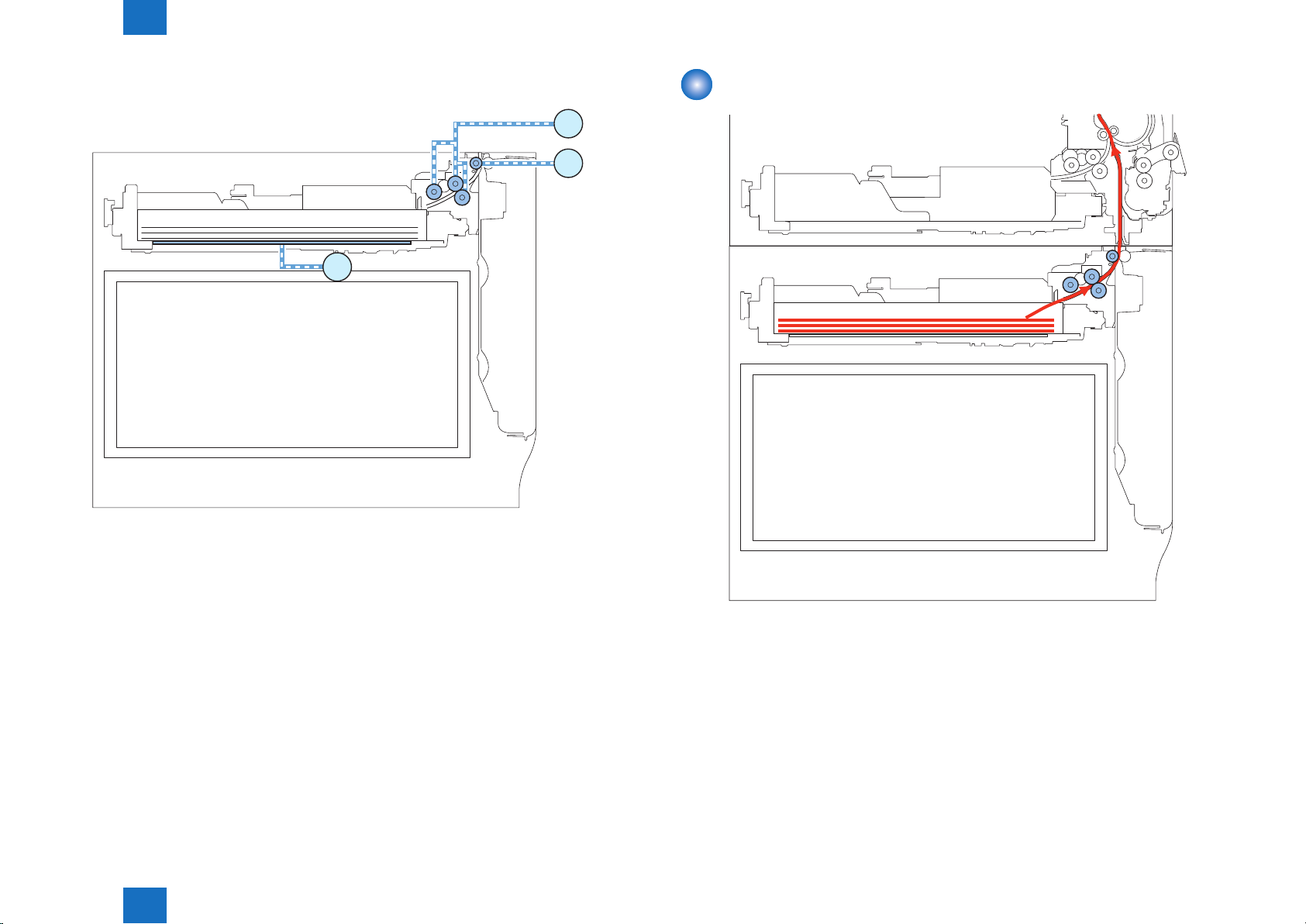
■Route of Drive
Paper Path
M102
M106
M104
Cassette 2
F-2-3
M102 Cassette 2 pickup Motor
M104 Cassette 2 Lifter Motor
M106 Cassette 2 Pullout Motor
Technology > Basic conguration > Paper Path
2
F-2-4
2-3
2
Technology > Controls > Overview
2-4
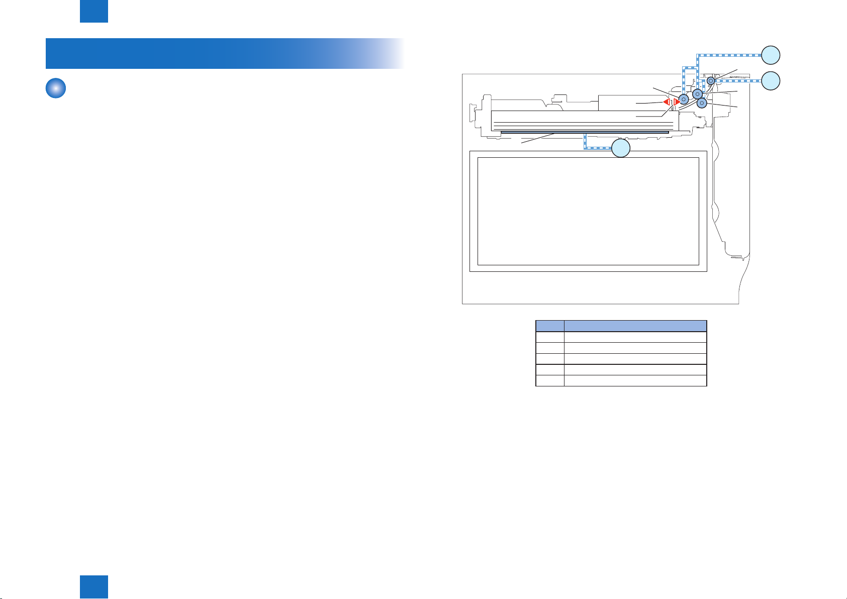
Controls
Overview
Paper inside a cassette is lifted up by the Lifter Plate.
The Lifter Plate rises by the rotation of the Cassette 2 Lifter Motor (M104). When the Pickup
Roller comes in contact with the surface of paper, paper is picked up by rotation of the
Cassette 2 pickup Motor (M102), and only a single sheet of paper is moved to the feed path
by the Cassette Feed Roller and the Cassette Separation Roller. Then, it is moved to the Pre-
registration Roller by the rotation of the Cassette 2 Pullout Motor (M106).
The Cassette 2 Pickup Roller, the Cassette 2 Feed Roller and Cassette 2 Separation Roller
are driven by the Cassette 2 Pickup Motor (M102) while the Cassette 2 Vertical Path Roller is
moved by the rotation of the Cassette 2 Pullout Motor (M106).
[5]
[1]
PS104
PS107
M104
No. Parts Name
[1] Cassette 2 pickup Roller
[2] Cassette 2 vertical path Roller
[3] Cassette 2 feed Roller
[4] Cassette 2 separation Roller
[5] Cassette 2 Lifting Plate
M102
[2]
M106
[3]
[4]
F-2-5
T-2-2
Technology > Controls > Overview
2
2-4
2
Technology > Controls > Overview > Paper Size Detection Control
2-5
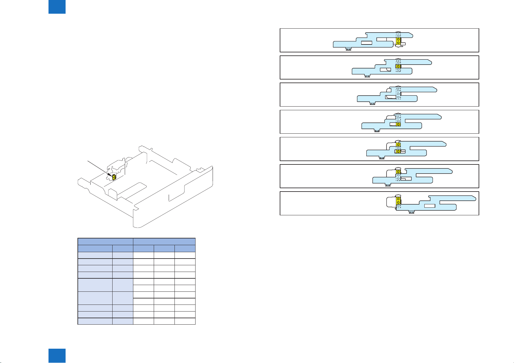
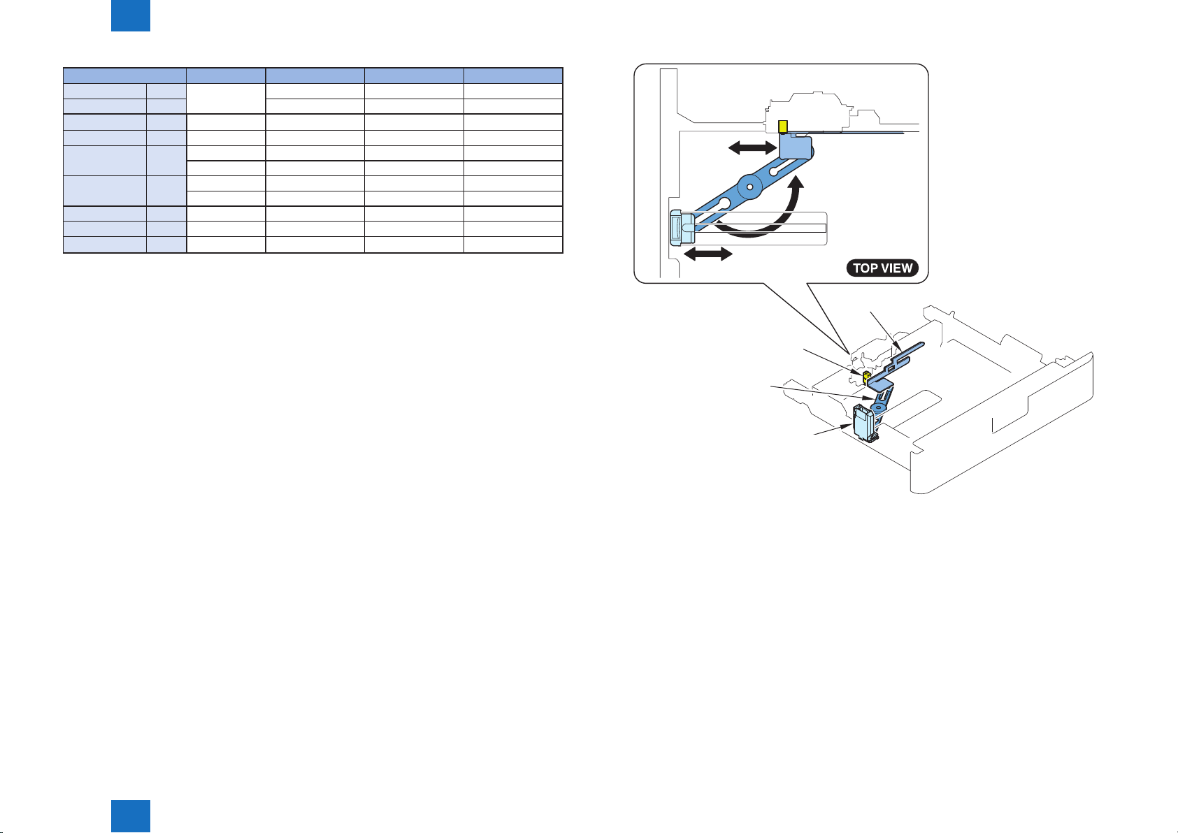
■Paper Size Detection Control
The paper size in the cassette is automatically detected by the "Cassette Size Switch" after
the position of the Guide Plate is adjusted and the cassette is installed in the host machine.
By shifting the Guide Plate, concavo-convex area of the Cassette Size Dial is switched
and the Cassette Size Switch at the printer side is switched. The switch consists of 3
microswitches, and the length is detected in accordance with the combination of ON/OFF.
(When the switch is pressed: ON) For standard size paper, any of AB conguration, inch
conguration, or AK conguration can be used. However, distinction between A5-R and
STMT-R should be made manually on the check screen.
Distinction between EXEC-R and 16K-R, and between LTR-R and 16K-R is automatically
made according to the country setting.
*: Whether to select A5-R or STMT-R can be registered in the user mode setting.
Settings/Registration > Preferences > Paper Settings > A5R/STMTR Paper Selection
Setting value per cassette: A5-R. STMT-R
Cassette Size Switch
A5-R
[1]
STMT-R
[2] B5-R
EXEC-R
[3]
16K-R
16K-R
[4]
LTR-R
[5] LTR-R
[6] A4-R
[7] LGL
Length Detection
Size Length 1 2 3
A5-R 210.0 ON OFF OFF
STMT-R 215.9 ON OFF OFF
B5-R 257.0 ON OFF ON
EXEC-R 267.0 ON ON ON
16K-R 270.0 ON ON ON
ON ON OFF
LTR-R 279.4 ON ON OFF
OFF ON OFF
A4-R 297.0 OFF ON ON
LGL 355.6 OFF OFF ON
(No cassette) - OFF OFF OFF
Technology > Controls > Overview > Paper Size Detection Control
2
F-2-7
F-2-6
T-2-3
2-5
2
Technology > Controls > Overview > Paper Size Detection Control
Paper size*1 All modes AB conguration Inch-conguration AK conguration
A5-R 210.0 [1] [1] - [1]
STMT-R 215.9 - [1] B5-R 257.0 [2] [2] Paper load error Paper load error
EXEC-R 267.0 [3] Paper load error [3] 16K-R 270.0 [3] Paper load error - [3]
[4] Paper load error - [4]
LTR-R 279.4 [4] Paper load error [4] -
[5] Paper load error [5] Paper load error
A4-R 297.0 [6] [6] Paper load error [6]
LGL 355.6 [7] Paper load error [7] Paper load error
(No cassette)*2 - [8] - - -
T-2-4
*1 Paper sizes can be registered in user mode settings.
[Settings/Registration] > [Preferences] > [Paper Settings] > [Paper Type Settings]
*2 Presence of the cassette is detected when the size switch is pushed.
(If no switch is pushed, it is judged as no cassette.)
2-6
Size Plate
Cassette
Size Switch
Link Arm
Technology > Controls > Overview > Paper Size Detection Control
2
Guide Plate
F-2-8
2-6
2
Technology > Controls > Overview > Paper Level Detection Control
2-7
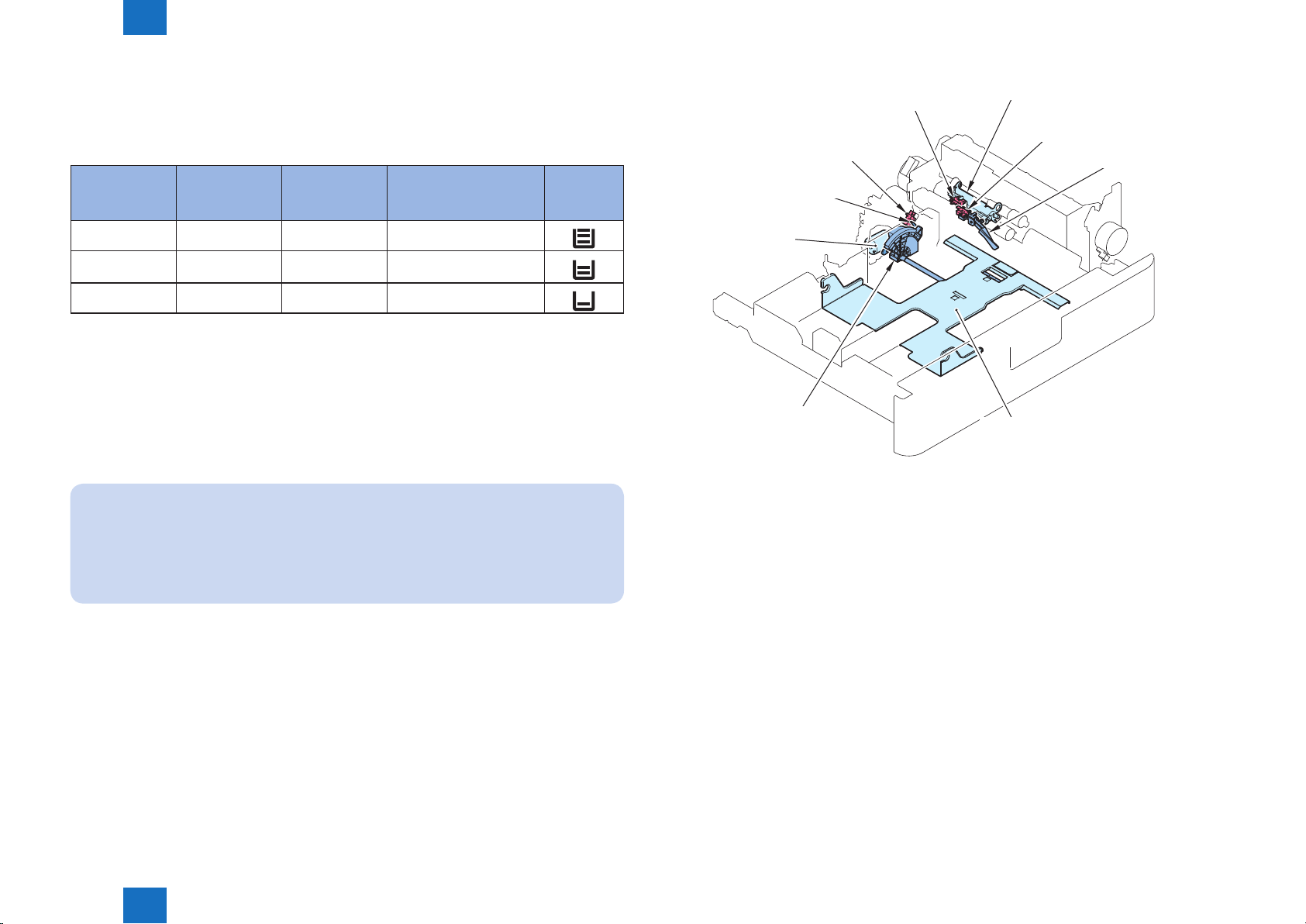
■Paper Level Detection Control
Paper level inside the cassette is detected by the sensors shown in the following table.
The paper level in the cassette is detected by the Cassette Lifter Motor, Cassette Paper
Sensor, Cassette Paper Surface Sensor, and Cassette Paper Level Sensor.
Cassette Paper
Sensor
OFF ON OFF* 100% to 50%*
OFF ON OFF
OFF ON ON Approx. 50 sheets or less
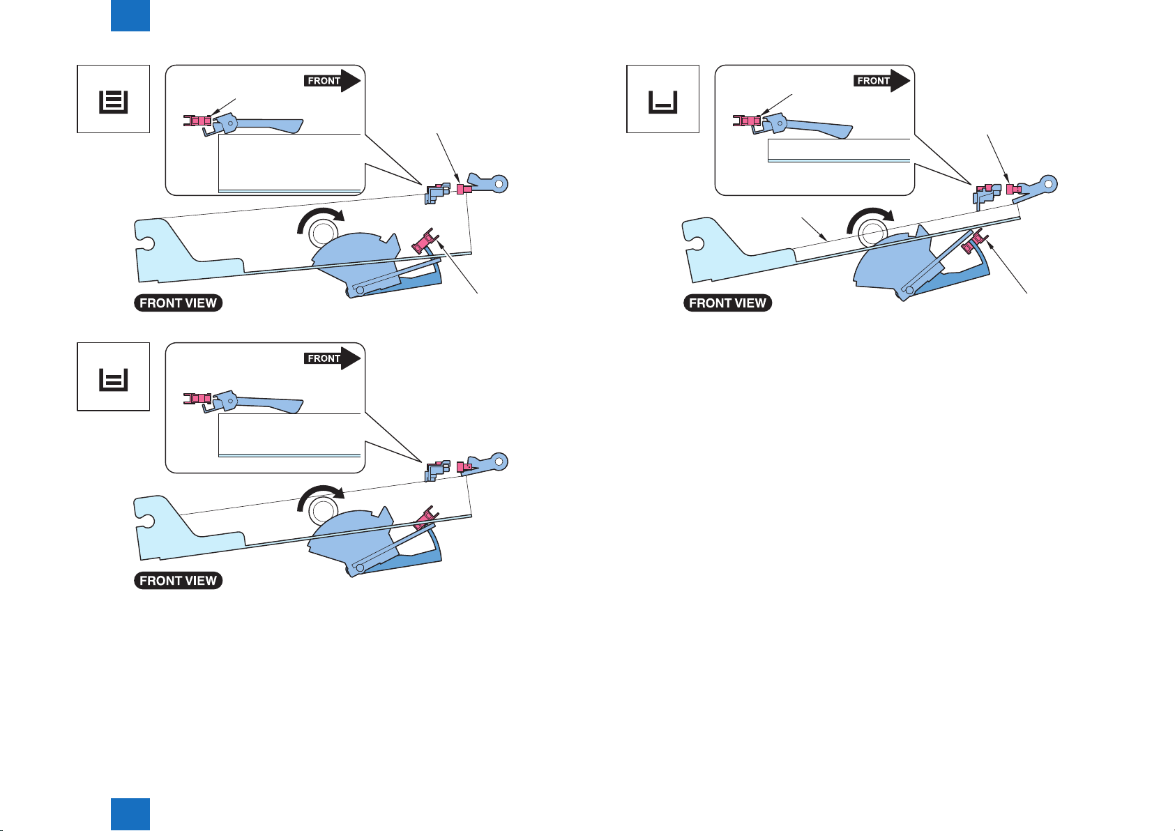
The control that switches the paper level display on the Control Panel is as follows:
• From 3 bars to 2 bars on the Control Panel:
The paper level is detected based on the time for which Cassette Lifter Motor is
continuously turned ON. Or, it is detected based on the time from when the Cassette Paper
Sensor is turned ON to when the Cassette Paper Surface Sensor is turned ON.
The paper level during paper feed is detected based on the number of times the Cassette
Lifter Plate is lifted up.
Related Service Mode
*: The paper level in the cassette is displayed by executing the following service mode.
You can adjust the timing of switching the scale from "3" to "2".
Lv.2) COPIER > ADJUST > CST-ADJ > CST-VLMX (Threshold adjustment for detecting
the level in the cassette X)
X indicates the cassette number (1 to 4).
Cassette Paper
Surface Sensor
Cassette Paper
Level Sensor
Paper level
Approx. 50% to approx. 50
sheets
Display on
the Control
Panel
T-2-5
Paper Level
Detection Lever
Cassette
Lifter Motor
Lifter Gear
Cassette Paper
Surface Sensor
Cassette Paper
Level Sensor
Lifting Plate
Detection Lever
Cassette
Paper Sensor
Paper Detection Lever
Lifting Plate
F-2-9
• From 2 bars to 1 bar on the Control Panel:
The Control Panel switches to display 1 bar when the Cassette Paper Level Sensor is
turned ON.
Technology > Controls > Overview > Paper Level Detection Control
2
2-7
2
Technology > Controls > Overview > Paper Level Detection Control
2-8
OFF
OFF
Cassette
Paper Sensor
Paper
Paper
Cassette Paper
Surface Sensor
OFF
OFF
Cassette Paper
Level Sensor
OFF
Cassette
Paper Sensor
OFF
Cassette Paper
Surface Sensor
Paper
OFF
Paper
ON
Cassette Paper
Level Sensor
F-2-11
Technology > Controls > Overview > Paper Level Detection Control
2
OFF
F-2-10
2-8
 Loading...